Resorptive intramedullary implant between two bones or two bone fragments
Prandi , et al. A
U.S. patent number 10,383,671 [Application Number 14/858,855] was granted by the patent office on 2019-08-20 for resorptive intramedullary implant between two bones or two bone fragments. This patent grant is currently assigned to Stryker European Holdings I, LLC. The grantee listed for this patent is Stryker European Holdings I, LLC. Invention is credited to Marc Augoyard, Judith Fellmann, Thomas Ledermann, Tristan Meusnier, Jacques Peyrot, Bernard Prandi.


| United States Patent | 10,383,671 |
| Prandi , et al. | August 20, 2019 |
Resorptive intramedullary implant between two bones or two bone fragments
Abstract
The invention relates to a resorptive intramedullary implant between two bones or two bone fragments. The implant includes a single-piece body (1) having a generally elongate shape and having, at each end, areas for anchoring to the bone portions in question, characterized in that one of said areas (A1) has a cylindrical cross-section while the other area (A2) has a flat cross-section.
| Inventors: | Prandi; Bernard (Rennes, FR), Augoyard; Marc (Tassin la Demi Lune, FR), Ledermann; Thomas (Eschenbach, CH), Meusnier; Tristan (Saint-Etienne, FR), Peyrot; Jacques (Tassin la Demi Lune, FR), Fellmann; Judith (Stafa, CH) | ||||||||||
|---|---|---|---|---|---|---|---|---|---|---|---|
| Applicant: |
|
||||||||||
| Assignee: | Stryker European Holdings I,
LLC (Kalamazoo, MI) |
||||||||||
| Family ID: | 40380661 | ||||||||||
| Appl. No.: | 14/858,855 | ||||||||||
| Filed: | September 18, 2015 |
Prior Publication Data
| Document Identifier | Publication Date | |
|---|---|---|
| US 20160008045 A1 | Jan 14, 2016 | |
Related U.S. Patent Documents
| Application Number | Filing Date | Patent Number | Issue Date | ||
|---|---|---|---|---|---|
| 13795946 | Mar 12, 2013 | 9168074 | |||
| 12918105 | Apr 9, 2013 | 8414583 | |||
| PCT/FR2009/051658 | Sep 2, 2009 | ||||
Foreign Application Priority Data
| Sep 9, 2008 [FR] | 08 56035 | |||
| Current U.S. Class: | 1/1 |
| Current CPC Class: | A61B 17/88 (20130101); A61F 2/4225 (20130101); A61B 17/68 (20130101); A61B 17/8605 (20130101); A61F 2/4241 (20130101); A61B 17/1655 (20130101); A61B 17/7233 (20130101); A61F 2002/30622 (20130101); A61B 17/7208 (20130101); A61B 17/7283 (20130101); A61F 2002/30878 (20130101); A61F 2002/30062 (20130101); A61F 2002/3085 (20130101); A61B 17/7225 (20130101); A61B 2017/00862 (20130101); A61B 2017/681 (20130101); A61B 2017/8655 (20130101); A61F 2210/0004 (20130101); A61B 17/7266 (20130101); A61F 2002/30563 (20130101) |
| Current International Class: | A61B 17/72 (20060101); A61B 17/86 (20060101); A61F 2/42 (20060101); A61B 17/88 (20060101); A61B 17/68 (20060101); A61B 17/16 (20060101); A61B 17/00 (20060101); A61F 2/30 (20060101) |
References Cited [Referenced By]
U.S. Patent Documents
| 1095054 | April 1914 | Wiesenfeld |
| 3462765 | August 1969 | Swanson |
| 3466669 | September 1969 | Flatt |
| 3593342 | July 1971 | Niebauer et al. |
| 3681786 | August 1972 | Lynch |
| 3739403 | June 1973 | Nicolle |
| 3805302 | April 1974 | Mathys |
| 3824631 | July 1974 | Burstein et al. |
| 3875594 | April 1975 | Swanson |
| D243716 | March 1977 | Treace et al. |
| 4091806 | May 1978 | Aginsky et al. |
| 4158893 | June 1979 | Swanson |
| 4204284 | May 1980 | Koeneman |
| 4237875 | December 1980 | Termanini |
| 4276660 | July 1981 | Laure |
| 4364382 | December 1982 | Mennen |
| 4367562 | January 1983 | Gauthier et al. |
| D277509 | February 1985 | Lawrence et al. |
| D277784 | February 1985 | Sgarlato et al. |
| 4522200 | June 1985 | Stednitz |
| D284099 | June 1986 | Laporta et al. |
| 4634382 | January 1987 | Kusano et al. |
| D291731 | September 1987 | Aikins |
| 4759768 | July 1988 | Hermann et al. |
| 4871367 | October 1989 | Christensen et al. |
| 4955916 | September 1990 | Carignan et al. |
| 4969909 | November 1990 | Barouk |
| 5011497 | April 1991 | Persson et al. |
| 5047059 | September 1991 | Saffar |
| 5062851 | November 1991 | Branemark |
| 5092896 | March 1992 | Meuli et al. |
| 5108443 | April 1992 | Branemark |
| 5133761 | July 1992 | Krouskop |
| 5179915 | January 1993 | Cohen et al. |
| 5190546 | March 1993 | Jervis |
| 5207712 | May 1993 | Cohen |
| 5326364 | July 1994 | Clift, Jr. et al. |
| 5360450 | November 1994 | Giannini |
| 5382251 | January 1995 | Hood |
| 5405400 | April 1995 | Linscheid et al. |
| 5405401 | April 1995 | Lippincott, III et al. |
| 5425776 | June 1995 | Cohen |
| 5425777 | June 1995 | Sarkisian et al. |
| 5454814 | October 1995 | Comte |
| 5464427 | November 1995 | Curtis et al. |
| 5474557 | December 1995 | Mai |
| 5480447 | January 1996 | Skiba |
| 5484443 | January 1996 | Pascarella et al. |
| 5507822 | April 1996 | Bouchon et al. |
| 5522903 | June 1996 | Sokolow et al. |
| 5554157 | September 1996 | Errico et al. |
| 5634925 | June 1997 | Urbanski |
| 5674297 | October 1997 | Lane et al. |
| 5702472 | December 1997 | Huebner |
| 5725585 | March 1998 | Zobel |
| 5782927 | July 1998 | Klawitter et al. |
| 5824095 | October 1998 | Di Maio, Jr. et al. |
| 5876434 | March 1999 | Flomenblit et al. |
| 5882444 | March 1999 | Flomenblit et al. |
| 5919193 | July 1999 | Slavitt |
| 5951288 | September 1999 | Sawa |
| 5958159 | September 1999 | Prandi |
| 5984970 | November 1999 | Bramlet |
| 5984971 | November 1999 | Faccioli et al. |
| 6011497 | January 2000 | Tsang et al. |
| 6017366 | January 2000 | Berman |
| 6146387 | November 2000 | Trott et al. |
| 6162234 | December 2000 | Freedland et al. |
| 6193757 | February 2001 | Foley et al. |
| 6197037 | March 2001 | Hair |
| 6200330 | March 2001 | Benderev et al. |
| 6248109 | June 2001 | Stoffella |
| 6261289 | July 2001 | Levy |
| 6319284 | November 2001 | Rushdy et al. |
| 6342076 | January 2002 | Lundborg |
| 6352560 | March 2002 | Poeschmann et al. |
| 6383223 | May 2002 | Baehler et al. |
| 6386877 | May 2002 | Sutter |
| 6395031 | May 2002 | Foley et al. |
| 6423097 | July 2002 | Rauscher |
| 6428634 | August 2002 | Besselink et al. |
| 6454808 | September 2002 | Masada |
| 6475242 | November 2002 | Bramlet |
| 6554833 | April 2003 | Levy et al. |
| 6689169 | February 2004 | Harris |
| 6692499 | February 2004 | Tormala et al. |
| 6699247 | March 2004 | Zucherman et al. |
| 6699292 | March 2004 | Ogilvie et al. |
| 6706045 | March 2004 | Lin et al. |
| 6773437 | August 2004 | Ogilvie et al. |
| 6811568 | November 2004 | Minamikawa |
| 6827741 | December 2004 | Reeder |
| 6833006 | December 2004 | Foley et al. |
| 6869449 | March 2005 | Ball et al. |
| 6896177 | May 2005 | Carter |
| 6981974 | January 2006 | Berger |
| 7025789 | April 2006 | Chow et al. |
| 7037342 | May 2006 | Nilsson et al. |
| 7041106 | May 2006 | Carver |
| 7052498 | May 2006 | Levy et al. |
| 7182787 | February 2007 | Hassler et al. |
| 7240677 | July 2007 | Fox |
| 7291175 | November 2007 | Gordon |
| 7537664 | May 2009 | O'Neill et al. |
| 7588603 | September 2009 | Leonard |
| 7601152 | October 2009 | Levy et al. |
| 7655042 | February 2010 | Foley et al. |
| 7670339 | March 2010 | Levy et al. |
| 7674426 | March 2010 | Grohowski, Jr. |
| 7780737 | August 2010 | Bonnard et al. |
| 7837738 | November 2010 | Reigstad et al. |
| 7842091 | November 2010 | Johnstone et al. |
| 7909880 | March 2011 | Grant |
| 7922765 | April 2011 | Reiley |
| 7955388 | June 2011 | Jensen et al. |
| 7976580 | July 2011 | Berger |
| 7993403 | August 2011 | Foley et al. |
| 8048173 | November 2011 | Ochoa |
| 8100983 | January 2012 | Schulte |
| 8162942 | April 2012 | Coati et al. |
| 8202305 | June 2012 | Reiley |
| 8262712 | September 2012 | Coilard-Lavirotte et al. |
| 8308779 | November 2012 | Reiley |
| 8388667 | March 2013 | Reiley et al. |
| 8394097 | March 2013 | Peyrot et al. |
| 8414583 | April 2013 | Prandi et al. |
| 8414648 | April 2013 | Reiley |
| 8425570 | April 2013 | Reiley |
| 8444693 | May 2013 | Reiley |
| 8470004 | June 2013 | Reiley |
| 8475456 | July 2013 | Augoyard et al. |
| 8529611 | September 2013 | Champagne et al. |
| 8597337 | December 2013 | Champagne |
| 8608785 | December 2013 | Reed et al. |
| 8685024 | April 2014 | Roman |
| 8715325 | May 2014 | Weiner et al. |
| 8728387 | May 2014 | Jones et al. |
| 8734462 | May 2014 | Reiley et al. |
| 8734491 | May 2014 | Seavey |
| 8834483 | September 2014 | Cheney et al. |
| 8834572 | September 2014 | Averous et al. |
| 8840623 | September 2014 | Reiley |
| 8840651 | September 2014 | Reiley |
| 8858601 | October 2014 | Reiley |
| 8864804 | October 2014 | Champagne et al. |
| 8920477 | December 2014 | Reiley |
| 8986348 | March 2015 | Reiley |
| 8992703 | March 2015 | O'Neill et al. |
| 8998999 | April 2015 | Lewis et al. |
| 9011504 | April 2015 | Reed |
| 9039743 | May 2015 | Reiley |
| 9044287 | June 2015 | Reed et al. |
| 9056014 | June 2015 | McCormick et al. |
| 9072562 | July 2015 | Weiner et al. |
| 9072564 | July 2015 | Reed et al. |
| 9089427 | July 2015 | Grohowski, Jr. |
| 9089431 | July 2015 | Grohowski, Jr. |
| D738504 | September 2015 | Weiner et al. |
| 9125704 | September 2015 | Reed et al. |
| 9135374 | September 2015 | Jones et al. |
| 9161789 | October 2015 | Peyrot et al. |
| 9168074 | October 2015 | Prandi et al. |
| 9180010 | November 2015 | Dong et al. |
| 9283007 | March 2016 | Augoyard et al. |
| 9403213 | August 2016 | Lapszynski |
| 9452002 | September 2016 | Roman et al. |
| 9492215 | November 2016 | Augoyard et al. |
| 9498266 | November 2016 | McCormick et al. |
| 9498273 | November 2016 | Thoren et al. |
| 2001/0025199 | September 2001 | Rauscher |
| 2001/0049529 | December 2001 | Cachia et al. |
| 2002/0019636 | February 2002 | Ogilvie et al. |
| 2002/0055785 | May 2002 | Harris |
| 2002/0065561 | May 2002 | Ogilvie et al. |
| 2002/0068939 | June 2002 | Levy et al. |
| 2002/0082705 | June 2002 | Bouman et al. |
| 2002/0169066 | November 2002 | Cassidy et al. |
| 2003/0040805 | February 2003 | Minamikawa |
| 2003/0069645 | April 2003 | Ball et al. |
| 2003/0120277 | June 2003 | Berger |
| 2003/0130660 | July 2003 | Levy et al. |
| 2004/0002759 | January 2004 | Ferree |
| 2004/0093081 | May 2004 | Nilsson et al. |
| 2004/0102853 | May 2004 | Boumann et al. |
| 2004/0138756 | July 2004 | Reeder |
| 2004/0220678 | November 2004 | Chow et al. |
| 2005/0119757 | June 2005 | Hassler et al. |
| 2005/0251265 | November 2005 | Calandruccio et al. |
| 2005/0261768 | November 2005 | Trieu |
| 2005/0283159 | December 2005 | Amara |
| 2006/0036322 | February 2006 | Reiley |
| 2006/0052725 | March 2006 | Santilli |
| 2006/0052878 | March 2006 | Schmieding |
| 2006/0074492 | April 2006 | Frey |
| 2006/0084998 | April 2006 | Levy et al. |
| 2006/0085075 | April 2006 | McLeer |
| 2006/0147332 | July 2006 | Jones et al. |
| 2006/0247787 | November 2006 | Rydell et al. |
| 2007/0038303 | February 2007 | Myerson et al. |
| 2007/0123993 | May 2007 | Hassler et al. |
| 2007/0142920 | June 2007 | Niemi |
| 2007/0156241 | July 2007 | Reiley et al. |
| 2007/0162018 | July 2007 | Jensen |
| 2007/0185584 | August 2007 | Kaufmann et al. |
| 2007/0213831 | September 2007 | de Cubber |
| 2007/0239158 | October 2007 | Trieu et al. |
| 2008/0039949 | February 2008 | Meesenburg et al. |
| 2008/0132894 | June 2008 | Coilard-Lavirotte et al. |
| 2008/0154385 | June 2008 | Trail et al. |
| 2008/0177262 | July 2008 | Augoyard et al. |
| 2008/0195219 | August 2008 | Wiley et al. |
| 2008/0221697 | September 2008 | Graser |
| 2008/0221698 | September 2008 | Berger |
| 2008/0234763 | September 2008 | Patterson et al. |
| 2008/0269908 | October 2008 | Warburton |
| 2009/0005821 | January 2009 | Chirico et al. |
| 2009/0012564 | January 2009 | Chirico et al. |
| 2009/0138096 | May 2009 | Myerson et al. |
| 2009/0254189 | October 2009 | Scheker |
| 2009/0254190 | October 2009 | Gannoe et al. |
| 2010/0010637 | January 2010 | Pequignot |
| 2010/0016905 | January 2010 | Greenhalgh et al. |
| 2010/0016982 | January 2010 | Solomons |
| 2010/0057214 | March 2010 | Graham et al. |
| 2010/0121390 | May 2010 | Kleinman |
| 2010/0131014 | May 2010 | Peyrot |
| 2010/0131072 | May 2010 | Schulte |
| 2010/0161068 | June 2010 | Lindner et al. |
| 2010/0185295 | July 2010 | Emmanuel |
| 2010/0228301 | September 2010 | Greenhalgh et al. |
| 2010/0249942 | September 2010 | Goswami et al. |
| 2010/0256731 | October 2010 | Mangiardi |
| 2010/0256770 | October 2010 | Hakansson et al. |
| 2010/0262254 | October 2010 | Lawrence et al. |
| 2011/0004317 | January 2011 | Hacking et al. |
| 2011/0093084 | April 2011 | Morton |
| 2011/0093085 | April 2011 | Morton |
| 2011/0144644 | June 2011 | Prandi et al. |
| 2011/0208304 | August 2011 | Justin et al. |
| 2011/0301652 | December 2011 | Reed et al. |
| 2012/0029579 | February 2012 | Bottlang et al. |
| 2012/0065692 | March 2012 | Champagne et al. |
| 2012/0089197 | April 2012 | Anderson |
| 2012/0259419 | October 2012 | Brown et al. |
| 2013/0053975 | February 2013 | Reed et al. |
| 2013/0060295 | March 2013 | Reed et al. |
| 2013/0066435 | March 2013 | Averous et al. |
| 2013/0123862 | May 2013 | Anderson et al. |
| 2013/0131822 | May 2013 | Lewis et al. |
| 2013/0150965 | June 2013 | Taylor et al. |
| 2013/0190761 | July 2013 | Prandi et al. |
| 2013/0190831 | July 2013 | Ek et al. |
| 2013/0231744 | September 2013 | Taylor et al. |
| 2013/0317559 | November 2013 | Leavitt et al. |
| 2013/0325077 | December 2013 | Champagne et al. |
| 2014/0005219 | January 2014 | Foster et al. |
| 2014/0039630 | February 2014 | Peyrot et al. |
| 2014/0058462 | February 2014 | Reed et al. |
| 2014/0107712 | April 2014 | Fallin et al. |
| 2014/0142715 | May 2014 | McCormick |
| 2014/0180428 | June 2014 | McCormick |
| 2014/0188239 | July 2014 | Cummings |
| 2014/0257509 | September 2014 | Dacosta et al. |
| 2014/0276827 | September 2014 | Roman et al. |
| 2014/0277554 | September 2014 | Roman et al. |
| 2014/0309747 | October 2014 | Taylor et al. |
| 2014/0316474 | October 2014 | Graham |
| 2014/0343615 | November 2014 | Cheney et al. |
| 2015/0011998 | January 2015 | McCormick et al. |
| 2015/0066097 | March 2015 | Biedermann |
| 2015/0073413 | March 2015 | Palmer et al. |
| 2015/0094778 | April 2015 | McCormick et al. |
| 2015/0112341 | April 2015 | Penzimer et al. |
| 2015/0112446 | April 2015 | Melamed et al. |
| 2015/0150607 | June 2015 | Chen et al. |
| 2015/0164563 | June 2015 | Lewis et al. |
| 2015/0223848 | August 2015 | McCormick |
| 2015/0223850 | August 2015 | Reed |
| 2015/0223853 | August 2015 | Appenzeller et al. |
| 2015/0342655 | December 2015 | Reed et al. |
| 2551021 | Mar 2005 | CA | |||
| 2243699 | Jan 2006 | CA | |||
| 2836654 | Jun 2014 | CA | |||
| 2837497 | Jun 2014 | CA | |||
| 0042808 | Dec 1981 | EP | |||
| 0420794 | Apr 1991 | EP | |||
| 0454645 | Oct 1991 | EP | |||
| 1300122 | Apr 2003 | EP | |||
| 1356794 | Nov 2003 | EP | |||
| 1582159 | Oct 2005 | EP | |||
| 1923012 | May 2008 | EP | |||
| 2228015 | Mar 2011 | EP | |||
| 2471477 | Jul 2012 | EP | |||
| 2471478 | Jul 2012 | EP | |||
| 2544633 | Jan 2013 | EP | |||
| 2749236 | Oct 2014 | EP | |||
| 2663838 | Jan 1992 | FR | |||
| 2725126 | Apr 1996 | FR | |||
| 2783702 | Mar 2000 | FR | |||
| 2787313 | Jun 2000 | FR | |||
| 2794019 | Dec 2000 | FR | |||
| 2801189 | May 2001 | FR | |||
| 2846545 | May 2004 | FR | |||
| 2884406 | Oct 2006 | FR | |||
| WO 2006109004 | Oct 2006 | FR | |||
| WO 2008129214 | Oct 2008 | FR | |||
| 2927529 | Aug 2009 | FR | |||
| 2935601 | Mar 2010 | FR | |||
| 2957244 | Sep 2011 | FR | |||
| 2119655 | Nov 1983 | GB | |||
| 2430625 | Apr 2007 | GB | |||
| 2430625 | Apr 2007 | GB | |||
| 60145133 | Jul 1985 | JP | |||
| 03-001854 | Aug 1991 | JP | |||
| 7303662 | Nov 1995 | JP | |||
| 2004535249 | Nov 2004 | JP | |||
| 3648687 | May 2005 | JP | |||
| 2007530194 | Nov 2007 | JP | |||
| 2008188411 | Aug 2008 | JP | |||
| 2008537696 | Sep 2008 | JP | |||
| 4695511 | Jun 2011 | JP | |||
| 5631597 | Nov 2014 | JP | |||
| 5645826 | Dec 2014 | JP | |||
| 20070004513 | Jan 2007 | KR | |||
| 20070022256 | Feb 2007 | KR | |||
| 101004561 | Jan 2011 | KR | |||
| 101235983 | Feb 2013 | KR | |||
| 9116014 | Oct 1991 | WO | |||
| 9625129 | Aug 1996 | WO | |||
| 9641596 | Dec 1996 | WO | |||
| 9726846 | Jul 1997 | WO | |||
| 9733537 | Sep 1997 | WO | |||
| 0117445 | Mar 2001 | WO | |||
| 03084416 | Oct 2003 | WO | |||
| 2005020830 | Mar 2005 | WO | |||
| 2005063149 | Jul 2005 | WO | |||
| 2005104961 | Nov 2005 | WO | |||
| 2006109004 | Oct 2006 | WO | |||
| 2008057404 | May 2008 | WO | |||
| 2008112308 | Sep 2008 | WO | |||
| 2008129214 | Oct 2008 | WO | |||
| 2009055952 | May 2009 | WO | |||
| 2009103085 | Aug 2009 | WO | |||
| 2010029246 | Mar 2010 | WO | |||
| 2011082343 | Jul 2011 | WO | |||
| 2011110784 | Sep 2011 | WO | |||
| 2011116078 | Sep 2011 | WO | |||
| 2011130229 | Oct 2011 | WO | |||
| 2012089330 | Jul 2012 | WO | |||
| 2012089331 | Jul 2012 | WO | |||
| 2013164819 | Nov 2013 | WO | |||
| 2014031947 | Feb 2014 | WO | |||
| 2014165123 | Oct 2014 | WO | |||
| 2015136212 | Sep 2015 | WO | |||
Other References
|
EP Notification for Application No. 09741356.1 dated Feb. 12, 2015. cited by applicant . International Search Report for PCT/FR2008/050453 dated Nov. 4, 2008. cited by applicant . International Search Report, PCT/FR2006/050345, dated Aug. 30, 2006. cited by applicant . Japanese Office Action for Application No. 2011-526540 dated Aug. 13, 2013. cited by applicant . HammerFix IP Fusion System, Hammertoe Deformity Surgical Technique, designed by Extremity Medical, published Mar. 31, 2014 (8 pages). cited by applicant . Intraosseous Fixation System, Hammertoe Surgical Technique, designed by OrthoHelix, published Aug. 23, 2012 (16 pages). cited by applicant. |
Primary Examiner: Hammond; Ellen C
Attorney, Agent or Firm: Lerner, David, Littenberg, Krumholz & Mentlik, LLP
Parent Case Text
CROSS REFERENCE TO RELATED APPLICATIONS
This application is a divisional of U.S. patent application Ser. No. 13/795,946, filed Mar. 12, 2013, now U.S. Pat. No. 9,168,074, which is a continuation of U.S. patent application Ser. No. 12/918,105, filed Oct. 29, 2010, now U.S. Pat. No. 8,414,583, which application is a U.S. national phase entry under 35 U.S.C. .sctn.371 of International Application No. PCT/FR2009/051658, filed Sep. 2, 2009, published as WO 2010/029246, which claims priority from French Patent Application No. 0856035, filed Sep. 9, 2008, whose entire disclosures are herewith incorporated by reference.
Claims
The invention claimed is:
1. A method for performing arthrodesis or osteosynthesis of first and second bone parts, the method comprising the steps of: inserting a first end of an implant into a first bone part, the implant including a second end extending from the first end, the second end having a longitudinal axis, a body portion, and a plurality of teeth projecting from the body portion, wherein at least a first tooth of the plurality of teeth is spaced from a second tooth of the plurality of teeth in a direction along the longitudinal axis of the second end, the first and second teeth extending from the body portion in a same direction, the first tooth, the second tooth, and the third tooth include coplanar surfaces, and at least the first tooth extending from the body portion in a different direction than a direction a third tooth of the plurality of teeth extends from the body portion; and fitting the second end into the second bone part.
2. The method of claim 1, further comprising the step of preparing the second bone part with a rasp prior to fitting the second end of the implant into the second bone part.
3. The method of claim 1, further comprising the step of tapping the first bone part to form a thread in the first bone part prior to inserting the first end of the implant into the first bone part.
4. The method of claim 1, wherein the second end has an opening in a median portion thereof adapted to enable elastic deformation of opposing sides thereof, and wherein the opposing sides are in a compressed state while the second end is being fitted into the second bone part, the opposing sides expanding once fitted within the second bone part.
5. The method of claim 1, wherein the combination of the body portion and the plurality of teeth form opposing flat surfaces parallel to the longitudinal axis.
6. The method of claim 1, wherein the first threaded end tapers in a direction away from the second end.
7. The method of claim 1, wherein the second end has an opening in a median portion thereof, and wherein the opening defines at least two spreadable arms.
8. The method of claim 1, wherein the first tooth, the second tooth, and the third tooth each include opposing flat surfaces, one of the opposing flat surfaces of each of the first tooth, the second tooth, and the third tooth being coplanar with respective ones of the opposing flat surfaces of each of the other of the first tooth, the second tooth, and the third tooth.
9. A method for performing arthrodesis or osteosynthesis of first and second bone parts, the method comprising the steps of: tapping a first bone part to form a thread in the first bone part; receiving a first threaded end of an implant into the first bone part, the implant including a second end extending from the first end, the second end having a longitudinal axis, a body portion, and a plurality of teeth projecting from the body portion, wherein at least a first tooth of the plurality of teeth is spaced from a second tooth of the plurality of teeth in a direction along the longitudinal axis of the second end, the first and second teeth extending from the body portion in a same direction, and at least the first tooth extending from the body portion in a different direction than a third tooth of the plurality of teeth, and wherein the second end has an opening defining at least two spreadable arms; and receiving the second end into the second bone part such that the arms spread into engagement with the second part by elasticity.
10. A method for performing arthrodesis or osteosynthesis of first and second bone parts, the method comprising the steps of: receiving a first end of an implant into a first bone part, the implant including a second end extending from the first end, the second end having a longitudinal axis, a body portion, and a plurality of teeth projecting from the body portion, wherein at least a first tooth of the plurality of teeth is spaced from a second tooth of the plurality of teeth in a direction along the longitudinal axis of the second end, the first and second teeth extending from the body portion in a same direction, and at least the first tooth extending from the body portion in a different direction than a third tooth of the plurality of teeth, and wherein the first tooth, the second tooth, and the third tooth each include opposing flat surfaces, one of the opposing flat surfaces of each of the first tooth, the second tooth, and the third tooth being coplanar with respective ones of the opposing flat surfaces of each of the other of the first tooth, the second tooth, and the third tooth; and receiving the second end into the second bone part.
11. The method of claim 10, wherein the second end defines an opening.
12. The method of claim 11, wherein the opening has first and second portions, the first portion of the opening being closer to the first end of the implant than the second portion of the opening, and wherein the second portion of the opening is exposed.
13. The method of claim 10, wherein the body portion has opposing flat surfaces parallel to the longitudinal axis.
14. The method of claim 10, further comprising abutting the first end against an edge defining an abutment between the first and second ends to prevent overinsertion of the implant into the first bone part.
15. The method of claim 14, wherein a face of the abutment defines a plane perpendicular to the longitudinal axis of the first end.
16. The method of claim 10, wherein a longitudinal axis through the first end is offset from the longitudinal axis of the second end by an angle between about 1 and about 30 degrees.
17. The method of claim 16, wherein the first end of the implant is received into the first bone part such that the offset is located at a position corresponding substantially to an arthrodesis line defined at the intersection of the first and second bone parts.
18. The method of claim 10, wherein the implant is made of resorptive material.
19. The method of claim 10, wherein the first and third teeth are positioned at the same axial location along the longitudinal axis of the second end.
20. The method of claim 10, wherein a cross-section of the body portion is non-circular.
21. The method of claim 10, wherein the opposing flat surfaces of the first tooth, the second tooth, and the third tooth define planes parallel to each other.
22. The method of claim 10, wherein the receiving steps includes threading the first end of the implant into the first bone part.
Description
FIELD OF THE INVENTION
The invention relates to the technical field of orthopedic implants, particularly for arthrodesis and osteosynthesis.
More particularly, the invention relates to an intramedullary implant for arthrodesis between two bone parts or osteosynthesis between two bone fragments, particularly in the case of the hand or foot.
BACKGROUND OF THE INVENTION
Different solutions have been proposed to achieve these functions.
For example, a solution comes from the teaching of patent application FR 2,884,406 [US 2008/0177262], of which the applicant of the present application is also the applicant. This patent describes an intramedullary osteosynthesis device constituted of an elongated body whose ends constitute anchor zones cooperating with the bone parts to be immobilized. The anchor zones are shaped and made of a material selected to enable insertion into the bone parts, then to ensure an anchor in the bone parts by preventing any rotational movement by resisting traction and by maintaining a compression force.
Another solution also comes from patent application FR 07.02003 [US 2010/0131014], also from the same applicant. This document describes an implant in the form of two anchor zones connected by a central zone and whose general shape is substantially inscribed in a very elongated rectangle of X-shape, so as to form in the anchor zones two legs adapted to move apart by elastic or shape-memory effect.
From this design, different criteria have been established to make the implant easy to place and efficient in order to create a primary and secondary stability for the osteosynthesis or arthrodesis site.
However, these solutions are not adapted for the case of an implant made of resorptive material.
BRIEF SUMMARY OF THE INVENTION
From this state of the art, the object that the invention proposes to attain is further improving the anchor and the stability of the implant as well as its adaptation to the morphology of the implantation site when the implant is made of resorptive material.
To solve such a problem, a resorptive intramedullary implant between two bones or two bone fragments has been designed and developed; it is constituted, in a known manner, of a single-piece body having a general elongated shape with, at each end, zones for anchoring to the bone parts being considered. According to the invention, one of the zones has a cylindrical shape, whereas the other zone is flat.
Advantageously, the implant is made of a resorptive material whose mechanical properties are determined to last the time necessary for the consolidation, so that the implant is resorbed after six months. For example, the implant is composed of lactic acid polymer or copolymer (PLA, PGA . . . ).
Considering the specific mechanical characteristics of resorptive materials, and to solve the given problem of improving anchor and stability, the cylindrical cross-section is threaded and tapers in the direction of its free end.
To solve the given problem of enabling a deformation by elasticity, thus causing an expansion adapted to the geometry of the site and to the properties of the material, the flat cross-section zone has, substantially in its median portion, an opening adapted to enable elastic deformation of the zone. The opening defines at least two anchor arms.
It therefore appears that the combination of a cylindrical and threaded anchor zone and a flat-sectioned anchor zone is particularly advantageous considering the problem to be solved.
To solve the given problem of resisting the shear and flexion forces susceptible of occurring in the area of the bone site, between the two anchor zones, the body has a central zone of transition adapted to resist the shear and flexion forces occurring in the area of the bone site and adapted to serve as an abutment.
From this basic design of the implant, the anchor zones are either coaxial or angularly offset by between about 1.degree. and 30.degree. and, advantageously, by 10.degree.. The bend between the anchor zones is located so as to substantially correspond to an arthrodesis line of the bones being considered.
BRIEF DESCRIPTION OF THE DRAWINGS
The invention is explained in more detail hereinafter with reference to the attached drawings, in which:
FIG. 1 is a perspective view of the implant;
FIG. 2 is a front view of the implant before insertion into the bone part in question;
FIG. 3 is a side view corresponding to FIG. 2;
FIG. 4 is a view like FIG. 2 showing the position of the anchor arms of the flat section after insertion;
FIG. 5 is a perspective view of another advantageous embodiment of the implant;
FIGS. 6 and 7 show the installation of the implant into two bone parts.
DETAILED DESCRIPTION
The implant according to the invention has a one-piece body 1 of elongated shape and having a first proximal zone A1 and a second distal zone A2. The entire implant body is made of a resorptive material whose mechanical properties are determined for the implant to be resorbed in no less than about 6 months. In one embodiment, the implant is composed of lactic acid polymer or copolymer (PLA, PGA . . . ).
As will be described later in the description, the zones A1 and A2 have anchor formations for the respective bone parts. Taking into account the specific characteristics of the resorptive material and to attain the given object of anchor and stability, the zone A1 is of a cylindrical shape section whereas the other zone A2 is flat.
The zone A1 has a generally cylindrical outer surface 1a with a limited taper toward its free end. The surface 1a has a helical rib forming a screwthread 1a1.
The zone A2 is flat and has substantially in its center, an opening 1b adapted to enable elastic deformation of the zone A2. More particularly, the opening 1b defines at least two anchor arms 1c and 1d, each having at least one outwardly projecting tooth 1c1, 1d1.
Advantageously, between the two zones A1 and A2 the body 1 has a central zone C for transition adapted to resist shear and flexion forces that can occur at the end of a bone. By way of nonlimiting example, this median zone C can have a length of about 3.5 mm and a thickness of about 2 mm, for an overall implant length comprised between about 15 and 25 mm and a diameter of about 2 or 3 mm at the zone A1.
In the embodiment shown in FIG. 1, the two zones A1 and A2 are coaxial.
To solve the problem of adaptation to the shape of the implantation site, the anchor zones A1 and A2 can be offset at an angle .alpha. adapted to the geometry of the bone site. This angle .alpha. is comprised between about 1.degree. and 30.degree. and, advantageously, on the order of 10.degree. when the implant is for foot arthrodesis (FIG. 5).
In this embodiment in which the two anchor zones are angularly offset, the bend is located so as to correspond substantially to the arthrodesis line of the bone parts being fused.
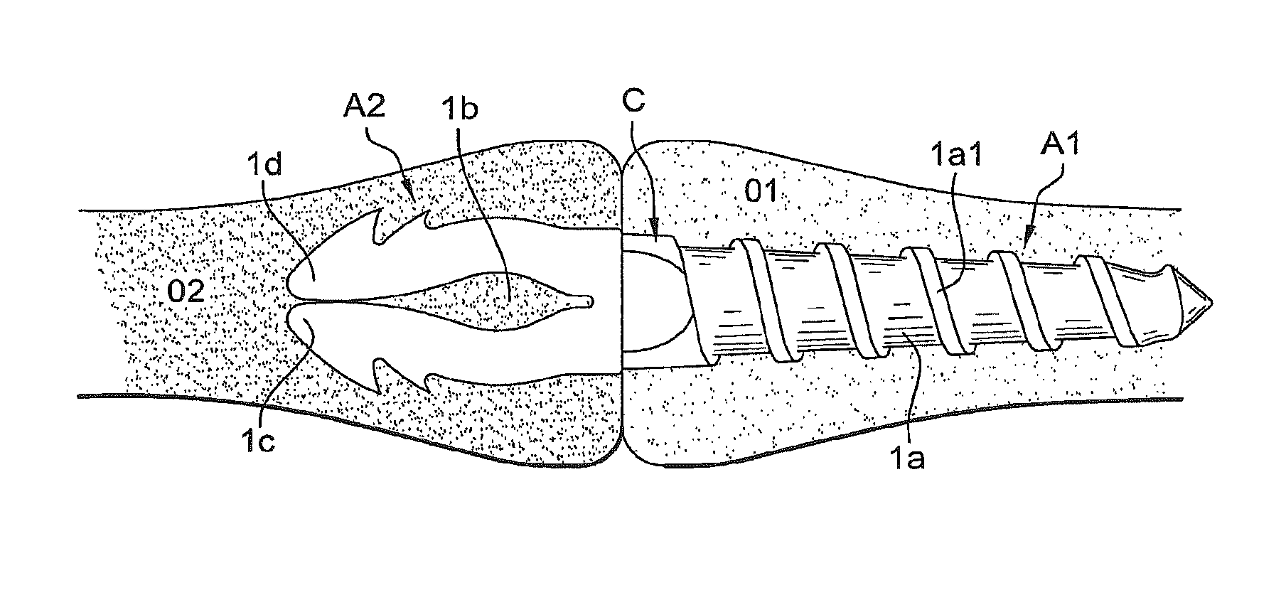
FIGS. 6 and 7 schematically show the positioning of the implant according to the invention between two bone parts O1 and O2. After suitable holes have been made in the bone by a rasp-type tool, the operator screws the thread 1a into the bone part O1 substantially up to the median zone C that serves as abutment preventing the implant from sinking too deeply into the bone (FIG. 6). The operator then fits the second bone part O2 back onto the anchor arms 1d and 1c of the zone A2, the anchor arms then spread and tighten by elasticity (FIG. 7).
The operative technique can be the following:
Drilling of the two holes with a conventional drill;
Preparation of the holes with a rasp for the flat side and a bone tap to form the inner screw thread on the cylindrical side;
Use of a screwdriver with a gripper end;
Screwing in the cylindrical side P1 [A1] for an arthrodesis IPP of the foot;
Fitting of the bone back onto the flat side [A2] of the implant.
The advantages are readily apparent from the description; in particular, it is to be emphasized and understood that the combination of the two anchor zones A1 and A2 of cylindrical and a flat shape, respectively, significantly enhances anchor and stability of the implant adapted to the geometry of the bone site and to the material properties, namely, a resorptive material.
* * * * *
D00000
D00001
D00002
D00003
D00004
XML
uspto.report is an independent third-party trademark research tool that is not affiliated, endorsed, or sponsored by the United States Patent and Trademark Office (USPTO) or any other governmental organization. The information provided by uspto.report is based on publicly available data at the time of writing and is intended for informational purposes only.
While we strive to provide accurate and up-to-date information, we do not guarantee the accuracy, completeness, reliability, or suitability of the information displayed on this site. The use of this site is at your own risk. Any reliance you place on such information is therefore strictly at your own risk.
All official trademark data, including owner information, should be verified by visiting the official USPTO website at www.uspto.gov. This site is not intended to replace professional legal advice and should not be used as a substitute for consulting with a legal professional who is knowledgeable about trademark law.