Machining tool and method for manufacturing a machining tool
Ach , et al.
U.S. patent number 10,369,636 [Application Number 14/676,567] was granted by the patent office on 2019-08-06 for machining tool and method for manufacturing a machining tool. This patent grant is currently assigned to KENNAMETAL INC.. The grantee listed for this patent is Kennametal Inc.. Invention is credited to Eduard Ach, Christoph Gey.


| United States Patent | 10,369,636 |
| Ach , et al. | August 6, 2019 |
Machining tool and method for manufacturing a machining tool
Abstract
A machining tool, in the area of a tool tip, includes an integrated cooling structure for transporting a coolant. The cooling structure is optionally or in combination designed as a porous structure or at least one cooling channel having a bent reversing segment, so that two channel segments are oriented in opposite directions. The cooling structure is integrated into a base body of a carrier tool. According to a method of the invention, the cooling structure is manufactured by means of a 3D printing method.
| Inventors: | Ach; Eduard (Mossbach, DE), Gey; Christoph (Zirndorf, DE) | ||||||||||
|---|---|---|---|---|---|---|---|---|---|---|---|
| Applicant: |
|
||||||||||
| Assignee: | KENNAMETAL INC. (Latrobe,
PA) |
||||||||||
| Family ID: | 54249954 | ||||||||||
| Appl. No.: | 14/676,567 | ||||||||||
| Filed: | April 1, 2015 |
Prior Publication Data
| Document Identifier | Publication Date | |
|---|---|---|
| US 20150298221 A1 | Oct 22, 2015 | |
Foreign Application Priority Data
| Apr 17, 2014 [DE] | 10 2014 207 510 | |||
| Current U.S. Class: | 1/1 |
| Current CPC Class: | B23B 51/06 (20130101); B23C 5/28 (20130101); B23B 2251/02 (20130101); B23C 2210/03 (20130101) |
| Current International Class: | B23B 51/06 (20060101); B23C 5/28 (20060101) |
References Cited [Referenced By]
U.S. Patent Documents
| 385088 | June 1888 | Benzie |
| 864756 | August 1907 | Phillips |
| 1476019 | December 1923 | Lowry |
| 1781863 | November 1930 | Shoemaker |
| 1951856 | March 1934 | Balke |
| 1965950 | July 1934 | Walker |
| 2289065 | July 1942 | Oliver |
| 2289344 | July 1942 | Cedarleaf |
| 2682414 | June 1954 | Richardson |
| 3455000 | July 1969 | Flaherty |
| 3646679 | March 1972 | Naugle |
| 3654681 | April 1972 | Stein |
| 3705447 | December 1972 | Kollar |
| 3754309 | August 1973 | Jones |
| 3857305 | December 1974 | Lichtman |
| 3911543 | October 1975 | Sorice |
| 4229640 | October 1980 | Castellani |
| 4373518 | February 1983 | Kaiser |
| 4459458 | July 1984 | Vetsch |
| 4481016 | November 1984 | Campbell |
| 4505626 | March 1985 | Benhase |
| 4591302 | May 1986 | Lovendahl |
| 4714385 | December 1987 | Komanduri |
| 4725171 | February 1988 | DeTorre |
| 4728231 | March 1988 | Kunimori |
| 4749618 | June 1988 | Kawaguchi |
| 4755237 | July 1988 | Lemelson |
| 4797138 | January 1989 | Komanduri |
| 4826364 | May 1989 | Grunsky |
| 4844668 | July 1989 | Pettersson |
| 4849602 | July 1989 | Gardner |
| D305498 | January 1990 | Lassiter |
| 4898499 | February 1990 | Tsujimura |
| 4946319 | August 1990 | Lyon |
| 4987800 | January 1991 | Gasan |
| 5022801 | June 1991 | Anthony |
| 5026960 | June 1991 | Slutz |
| 5066170 | November 1991 | Berryer |
| 5078551 | January 1992 | Oomen |
| 5098232 | March 1992 | Benson |
| 5160824 | November 1992 | Babel |
| 5178645 | January 1993 | Nakamura |
| 5181321 | January 1993 | Gouttebarge |
| 5205680 | April 1993 | Lindstedt |
| 5239160 | August 1993 | Sakura |
| 5247923 | September 1993 | Lebourg |
| 5272940 | December 1993 | Diskin |
| 5342151 | August 1994 | Friedmann |
| 5362183 | November 1994 | Alario |
| 5387776 | February 1995 | Preiser |
| 5388484 | February 1995 | Bogner |
| 5433280 | July 1995 | Smith |
| 5488761 | February 1996 | Leone |
| 5634933 | June 1997 | McCombs |
| 5643523 | July 1997 | Simpson |
| 5685671 | November 1997 | Packer |
| 5722803 | March 1998 | Battaglia |
| 5776355 | July 1998 | Martin |
| 5799553 | September 1998 | Billatos |
| 5820313 | October 1998 | Weber |
| 5851465 | December 1998 | Bredt |
| 5853268 | December 1998 | Simpson |
| 5906053 | May 1999 | Turner |
| 5957006 | September 1999 | Smith |
| 6030156 | February 2000 | Andronica |
| 6045301 | April 2000 | Kammermeier |
| 6053669 | April 2000 | Lagerberg |
| 6062753 | May 2000 | Hadtke |
| 6116823 | September 2000 | Mihic |
| 6116825 | September 2000 | Kammermeier |
| 6146476 | November 2000 | Boyer |
| 6161990 | December 2000 | Oles |
| 6200514 | March 2001 | Meister |
| 6274206 | August 2001 | Turchan et al. |
| 6315502 | November 2001 | Maurer |
| 6315505 | November 2001 | Moore |
| 6353204 | March 2002 | Spaay |
| 6353205 | March 2002 | Izard |
| 6354361 | March 2002 | Sachs et al. |
| 6394466 | May 2002 | Matsumoto |
| 6402438 | June 2002 | Boyer |
| 6413286 | July 2002 | Swei et al. |
| 6447560 | September 2002 | Jensen |
| 6454030 | September 2002 | Findley et al. |
| 6472029 | October 2002 | Skszek |
| 6521864 | February 2003 | Bertez |
| 6524036 | February 2003 | Koelker |
| 6526327 | February 2003 | Kar et al. |
| 6554010 | April 2003 | Hirose |
| 6581671 | June 2003 | Butcher et al. |
| 6607533 | August 2003 | Del Rio |
| 6612204 | September 2003 | Droese |
| 6629559 | October 2003 | Sachs et al. |
| 6655481 | December 2003 | Findley et al. |
| 6692199 | February 2004 | Andersson |
| 6712564 | March 2004 | Hughes |
| 6715968 | April 2004 | Taegstroem |
| 6733603 | May 2004 | Wu |
| 6776219 | August 2004 | Cornie et al. |
| 6808340 | October 2004 | Travez |
| 6814926 | November 2004 | Geving et al. |
| 6859681 | February 2005 | Alexander |
| 6929426 | August 2005 | Thiele |
| 7002100 | February 2006 | Wu |
| 7112020 | September 2006 | Sheffler |
| 7179023 | February 2007 | Goudemond |
| 7186369 | March 2007 | Hardro et al. |
| 7189032 | March 2007 | Goudemond |
| 7226254 | June 2007 | Friedrichs |
| 7255821 | August 2007 | Priedeman, Jr. et al. |
| 7258720 | August 2007 | Fuwa et al. |
| 7313991 | January 2008 | Penkert |
| 7322776 | January 2008 | Webb |
| 7432471 | October 2008 | Yamazaki |
| 7461684 | December 2008 | Liu et al. |
| 7476067 | January 2009 | Borschert |
| 7496424 | February 2009 | Froeschner et al. |
| 7533713 | May 2009 | Pfeifer et al. |
| 7614831 | November 2009 | Liu |
| 7634957 | December 2009 | Ghosh |
| 7785046 | August 2010 | Beckington |
| 7832456 | November 2010 | Calnan et al. |
| 7832457 | November 2010 | Calnan et al. |
| 7930054 | April 2011 | Slaughter et al. |
| 8052765 | November 2011 | Cho et al. |
| 8109350 | February 2012 | Fang et al. |
| 8178033 | May 2012 | Dietrich et al. |
| 8221858 | July 2012 | Mannella et al. |
| 8308403 | November 2012 | Hecht |
| 8318076 | November 2012 | Wang et al. |
| 8333814 | December 2012 | Brackin et al. |
| 8383028 | February 2013 | Lyons |
| 8398396 | March 2013 | Taormina |
| 8460755 | June 2013 | Rodgers |
| 8509933 | August 2013 | Steingart et al. |
| 8522646 | September 2013 | Laird et al. |
| 8534963 | September 2013 | Luik |
| 8551395 | October 2013 | Belhadjhamida et al. |
| 8568649 | October 2013 | Balistreri et al. |
| 8746703 | June 2014 | Xu |
| 2001/0056309 | December 2001 | Jain et al. |
| 2003/0094730 | May 2003 | Dourfaye et al. |
| 2003/0118412 | June 2003 | Fukui |
| 2003/0210963 | November 2003 | Kakai |
| 2004/0107019 | June 2004 | Keshavmurthy et al. |
| 2004/0120777 | June 2004 | Noland |
| 2004/0120778 | June 2004 | Lach |
| 2004/0221696 | November 2004 | Matsuhashi |
| 2004/0258491 | December 2004 | Penkert |
| 2005/0238451 | October 2005 | Hartman |
| 2006/0039818 | February 2006 | Tsai et al. |
| 2006/0048615 | March 2006 | Treige |
| 2006/0144198 | July 2006 | Okajima |
| 2007/0006694 | January 2007 | Fujimoto |
| 2007/0212177 | September 2007 | Liu |
| 2007/0283786 | December 2007 | Kappmeyer |
| 2008/0065259 | March 2008 | Dietrich et al. |
| 2008/0075618 | March 2008 | Martin et al. |
| 2008/0080937 | April 2008 | Hecht |
| 2008/0253849 | October 2008 | Yoshinaga |
| 2008/0260479 | October 2008 | Kammermeier |
| 2008/0260964 | October 2008 | Bagavath-Singh et al. |
| 2009/0035075 | February 2009 | Hecht |
| 2009/0035411 | February 2009 | Seibert et al. |
| 2009/0114628 | May 2009 | DiGiovanni |
| 2010/0086373 | April 2010 | Kleiner |
| 2010/0172703 | July 2010 | Neubold |
| 2010/0242696 | September 2010 | Digernes |
| 2010/0254772 | October 2010 | Rozzi |
| 2010/0270757 | October 2010 | Beckington |
| 2011/0156304 | June 2011 | Walker et al. |
| 2011/0210096 | September 2011 | Raji |
| 2011/0266068 | November 2011 | Eason et al. |
| 2011/0291331 | December 2011 | Scott |
| 2012/0018924 | January 2012 | Swanson et al. |
| 2012/0068378 | March 2012 | Swanson et al. |
| 2012/0070523 | March 2012 | Swanson et al. |
| 2012/0103701 | May 2012 | Cho et al. |
| 2012/0135166 | May 2012 | Berglund |
| 2012/0141215 | June 2012 | Choi |
| 2012/0183802 | July 2012 | Bruck |
| 2012/0232857 | September 2012 | Fisker et al. |
| 2012/0326356 | December 2012 | Martin |
| 2013/0004680 | January 2013 | Godfrey |
| 2013/0015596 | January 2013 | Mozeika et al. |
| 2013/0034399 | February 2013 | Omagari |
| 2013/0040051 | February 2013 | Mourou et al. |
| 2013/0059509 | March 2013 | Deopura et al. |
| 2013/0088364 | April 2013 | Bittar et al. |
| 2013/0101746 | April 2013 | Keremes et al. |
| 2013/0105230 | May 2013 | Brackin et al. |
| 2013/0136868 | May 2013 | Bruck et al. |
| 2013/0161439 | June 2013 | Beery et al. |
| 2013/0161442 | June 2013 | Mannella et al. |
| 2013/0164960 | June 2013 | Swanson et al. |
| 2013/0170171 | July 2013 | Wicker et al. |
| 2013/0209600 | August 2013 | Tow |
| 2013/0220570 | August 2013 | Sears et al. |
| 2013/0220572 | August 2013 | Rocco et al. |
| 2013/0221191 | August 2013 | Sears et al. |
| 2013/0223943 | August 2013 | Gey et al. |
| 2013/0224423 | August 2013 | Mikulak et al. |
| 2013/0247475 | September 2013 | Lind et al. |
| 2013/0248260 | September 2013 | Ganz |
| 2013/0255346 | October 2013 | Danby et al. |
| 2013/0277121 | October 2013 | Stevens et al. |
| 2014/0321931 | October 2014 | Gey |
| 2015/0042050 | February 2015 | Haimer |
| 2015/0298221 | October 2015 | Ach |
| 2015/0367423 | December 2015 | Voss |
| 2016/0031015 | February 2016 | Doi |
| 2405109 | Jan 2006 | CA | |||
| 10141897 | May 1990 | CN | |||
| 1689739 | Nov 2005 | CN | |||
| 1910003 | Feb 2007 | CN | |||
| 101068644 | Nov 2007 | CN | |||
| 201579425 | Sep 2010 | CN | |||
| 102056696 | May 2011 | CN | |||
| 102427858 | Apr 2012 | CN | |||
| 19730539 | Apr 1999 | DE | |||
| 19860585 | Jul 2000 | DE | |||
| 10016464 | Oct 2001 | DE | |||
| 10336923 | Mar 2005 | DE | |||
| 102004042775 | Mar 2006 | DE | |||
| 19901777 | Aug 2007 | DE | |||
| 102006005401 | Aug 2007 | DE | |||
| 202010015446 | Feb 2011 | DE | |||
| 191203 | Aug 1986 | EP | |||
| 728912 | Aug 1996 | EP | |||
| 843609 | Sep 1999 | EP | |||
| 1537930 | Jun 2005 | EP | |||
| 1534451 | Feb 2007 | EP | |||
| 2367669 | Sep 2011 | EP | |||
| 2646185 | Oct 2013 | EP | |||
| 2646224 | Oct 2013 | EP | |||
| 2646641 | Oct 2013 | EP | |||
| 2654412 | Oct 2013 | EP | |||
| 2500996 | Oct 2013 | GB | |||
| S61109606 | May 1986 | JP | |||
| H04226826 | Aug 1992 | JP | |||
| H0623615 | Feb 1994 | JP | |||
| H06182613 | Jul 1994 | JP | |||
| H08206133 | Aug 1996 | JP | |||
| H1150254 | Feb 1999 | JP | |||
| 2002066821 | Mar 2002 | JP | |||
| 2004216483 | Aug 2004 | JP | |||
| 2008062369 | Mar 2008 | JP | |||
| 2008081840 | Apr 2008 | JP | |||
| 2009006436 | Jan 2009 | JP | |||
| 2010502460 | Jan 2010 | JP | |||
| 2005025779 | Oct 2005 | WO | |||
| WO2007104065 | Sep 2007 | WO | |||
| WO2007127899 | Nov 2007 | WO | |||
| 2011135512 | Nov 2011 | WO | |||
| 2012073099 | Jun 2012 | WO | |||
| 2012146694 | Nov 2012 | WO | |||
| 2012071449 | Jan 2013 | WO | |||
| 2013030064 | Mar 2013 | WO | |||
| 2013087515 | Jun 2013 | WO | |||
| 2013124691 | Aug 2013 | WO | |||
| 2013126981 | Sep 2013 | WO | |||
| 2013140146 | Sep 2013 | WO | |||
| 2013112217 | Oct 2013 | WO | |||
| 2013149659 | Oct 2013 | WO | |||
| 2013154723 | Oct 2013 | WO | |||
Other References
|
Beij, K. Hilding, Pressure Losses for Fluid Flow in 90 Degree Pipe Bends, Jul. 1938, National Bureau of Standards, Research Paper RP 1110. cited by examiner . English translation of DE 202010015446 U1, Feb. 2011. cited by examiner . English translation of DE 10016464 A1, Oct. 2001 (Year: 2001). cited by examiner . Feb. 12, 2016 Office action (3 months). cited by applicant . Jan. 30, 2017 Office action (3 months). cited by applicant . Apr. 19, 2017 First office action. cited by applicant . Nov. 3, 2016 Final Office Action. cited by applicant . Jun. 30, 2017 Final Office Action. cited by applicant . Jul. 7, 2017 Office action (3 months). cited by applicant . May 17, 2017 First office action. cited by applicant . Apr. 16, 2015 Search Report. cited by applicant . Aug. 2014--Technnologietrends--Mapal. cited by applicant . Aug. 19, 2014 Office Action. cited by applicant . Jul. 21, 2015 Final Office Action. cited by applicant . US 20110097162, Oct. 27, 2015 Office action (3 months). cited by applicant . Kessler, Hillary, Nov. 12, 2015 Final Office Action. cited by applicant . Oct. 24, 2017 First office action. cited by applicant . Nov. 17, 2017 Office action (3 months). cited by applicant . Jul. 26, 2011 International Search Report. cited by applicant . Fundamental Aspects in Maching of Metals with Short and Ultrashort Laser Pulses. cited by applicant . Lasers: Solve Every Task Perfectly, State-of-the-Art Laser Technology. cited by applicant . Oct. 18, 2016 Second Office Action. cited by applicant . Nov. 13, 2013 Second Office Action. cited by applicant . Dec. 27, 2017 First Office Action. cited by applicant . Jan. 12, 2018 Second Office Action. cited by applicant . Feb. 13, 2018 First Office Action. cited by applicant . May 29, 2018 Office Action (non-US). cited by applicant . Jul. 20, 2018 Office Action (non-US). cited by applicant . Jul. 27, 2018 Office action (3 months) (US Only). cited by applicant . Aug. 20, 2018 Foreign OA. cited by applicant . May 3, 2019 Foreign OA K-04401-CN-NP. cited by applicant . May 3, 2019 Foreign OA K-04400-CN-NP. cited by applicant. |
Primary Examiner: Snyder; Alan
Attorney, Agent or Firm: Bedsole; Matthew S.
Claims
What is claimed is:
1. A machining tool that extends in an axial direction along a rotational axis and comprising: a tool tip; a base body, the base body forming retaining webs between which a tool tip can be inserted and having an integrated cooling structure for conducting a coolant or lubricant, the cooling structure being integrated at least partly in the retaining webs; and a chip flute formed in the base body, the chip flute having a chip flute wall, wherein the cooling structure, at least in sections, is designed as a porous structure having a plurality of pores; wherein at least a portion of the porous structure is located in the retaining webs of the base body and the porous structure exits at an outlet point provided on the chip flute wall; and wherein the porous structure has a porosity ranging between 5% and 90%.
2. The machining tool as claimed in claim 1, further comprising an outer cladding at which the porous structure exits at the outlet point.
3. The machining tool as claimed in claim 1, wherein the outlet point is a planar outlet point.
4. A method for manufacturing a machining tool as claimed in claim 1, wherein the machining tool is manufactured with an integrated cooling structure at least partially with the aid of a 3D printing method.
5. The machining tool as claimed in claim 1, wherein the pores have an average pore size ranging between 15 and 45 .mu.m.
6. The machining tool as claimed in claim 1, wherein the pores of the porous structure are arranged in a honeycomb structure.
7. The machining tool as claimed in claim 1, wherein the pores of the porous structure are arranged in a bionic, random structure.
Description
CLAIM TO PRIORITY
This application is a National entry application of German Application No. 102014207510.6, filed on Apr. 17, 2014, the entire contents of which is incorporated herein by reference.
FIELD OF THE INVENTION
The invention relates to a machining tool, in particular a rotating tool such as a drill or milling tool, which extends in an axial direction and in the area of a tool tip comprises an integrated cooling structure for conducting a coolant. The invention additionally relates to a method for manufacturing a machining tool.
BACKGROUND OF THE INVENTION
Machining tools, in particular drills, usually comprise a clamping shaft extending in the axial direction to which a slotted cutting part connects, which extends up to a front tool tip, in particular a drill bit. In the case of such machining tools, which are also referred to as shank-type tools, recesses, particularly for coolant channels, are often implemented in the interior of the base body, as can be seen in EP 0 843 609 B1, for example.
Introducing cooling structures, e.g. coolant lines, in the area of the tool tip is very complex from a manufacturing point of view. In some cases, coolant outlets cannot be optimally positioned. Furthermore, there are various requirements for coolant/lubrication depending on the material being processed. Minimum quantity lubrication is often employed, which involves applying only small amounts of coolant/lubricant. In some cases, further reduction of coolant consumption is sought. In some applications, contact between coolant and the workpiece is undesired.
SUMMARY OF THE INVENTION
Proceeding from this background, the invention seeks to solve the problem of enabling efficient cooling or lubrication in the area of a tool tip of a machining tool.
The problem is solved according to the invention by a machining tool having the features of Claim 1. The machining tool is in particular a rotating tool, i.e. a machining tool which rotates around a rotational axis during operation. In this particular case it is a drill or milling tool.
The machining tool extends in an axial direction and preferably along a center axis, which in the case of rotating tools at the same time also constitutes the rotational axis. Integrated in the area of the tool tip is a cooling structure, by means of which coolant/lubricant is transported during operation. The cooling structure is designed, at least in sections, as a porous structure or comprises at least one cooling channel, which has a reversing segment so that two channel segments oriented in opposite directions are formed. Both options, which can also be used in combination with one another, allow the coolant/lubricant to be conducted in the area of the tool tip in a targeted, defined manner. The porous structure allows for comparatively extensive cooling/lubrication with only minor escape of coolant. With the aid of the cooling channel routed via a reversing section, targeted cutting areas can be supplied with coolant, resulting in only minor coolant need owing to the targeted orientation.
According to the invention, the machining tool is manufactured with a 3D printing method being employed at least for implementing the cooling structure. In a 3D printing method of this type, the body being manufactured is generally generated coat-by-coat or layer-by-layer, wherein, for the purpose of forming each layer with a specified geometry, powdery material is compacted with the aid of a laser, for example melted or sintered, so that a cohesive body is formed. The powder employed is, for example, metal or ceramic powder which typically has an average grain size ranging between 10 and 50 .mu.m. This special manufacturing method allows highly complex geometries, including in particular the porous structure or the reversing segment of the cooling structure, to be realized without difficulty.
The machining tool generally has at its front end a tool tip, which itself is designed as a cutting element or in the area of which one or more cutting elements are arranged. In the present invention, a tool tip is thus generally understood to mean the frontal end area of the machining tool. The machining tool is preferably designed as a modular carrier tool on which a replaceable cutting element (cutting insert) is attached to a (carrier) base body. According to a preferred variant, the tool tip itself is designed as a replaceable cutting insert. This component can be reversibly and replaceably attached to the base body by way of by way of clamping, for the example with the aid of fastening elements such as screws, or alternatively by means of simple twisting. For this purpose, this component is held clamped in particular between two retaining or clamping webs of the base body. The carrier tool is alternatively designed with plate seats for attaching (indexable) inserts. In this case the area of the plate seats is understood to mean the tool tip. In a non-modular, one-piece tool having, for example, major cutting edges cut into the end face area, a front end face area having an axial length, for example in the range of a nominal diameter, constitutes tool tip.
In the present invention, a porous structure is generally understood to mean a non-solid structure having a plurality of pores, i.e. air or gas inclusions, or also having a plurality of (micro-) channels, for example in the manner of a honeycomb structure or also a bionic, random structure. It is an open, in particular open-pored, pore structure, in which at least some of the individual pores are connected to one another so that, overall, channels are formed, and the entire pore structure is suitable for conducting coolant.
The porous structure expediently has a porosity ranging between 5 and 90%, i.e. 5 to 90 percent of the porous structure is composed of pores, i.e. air inclusions. In spite of this comparatively large pore volume, sufficiently high stability is still ensured. The pores preferably have an average pore size ranging between 15 and 45 .mu.m.
It is possible in principle to combine different structures with one another within the machining tool, and also to vary the structure within a section, i.e. change the porosity for example.
With regard to the porous structure, an outlet point is expediently provided at an outer cladding in the area of the tool tip, i.e. the porous structure protrudes to the outside and is not closed. This results in the special advantage that coolant can be conducted outward via the porous structure across as large a surface area as possible, even in small quantities, and optimally effective cooling or lubrication of large surface areas can be ensured at the same time. Unlike with coolant bores, only very small quantities escape per surface segment. In particular, the coolant feed is set such that the surfaces are virtually just wetted.
The outlet point is thus expediently a planar outlet point.
According to a first variant, the outlet point is located on a radially outer circumferential wall, in particular at what is referred to as the drill back. A coolant or lubricant can thus be introduced in a targeted manner via this outlet point into the area between the circumference of the machining tool and the workpiece being machined, in particular a borehole wall.
In an alternative variant, the outlet point is designed in a chip flute wall of a chip flute. A large-surface-area outlet point in particular facilitates highly efficient cooling of, for example, a chip to be transported away. The surface of the chip flute, i.e. the chip flute wall, is hereby efficiently cooled.
Finally, it is provided in a third variant that the outlet point is formed at the end face of a front end face, which is formed succeeding a major cutting edge against the direction of rotation.
The different variants for the outlet point can thus be arbitrarily combined with one another. Different porosities with differently sized pores can also be created, so that--at the same coolant pressure--different volumes of coolant/lubricant can be deliberately supplied at the individual outlet point via the differently designed porous structures.
In the embodiment variant with the cooling channel having a reversing segment, said cooling channel expediently has a channel outlet, which is purposefully oriented in the direction of a cutting element, in particular a cutting insert. The cutting insert is preferably a reversibly changeable cutting insert, in particular a cutting plate, preferably an indexable insert. In this embodiment variant, the channel outlet is thus directed at a plate seat. Alternatively, the cutting element is a tool tip designed as an insert or merely an cut-in cutting edge. Particularly in the case of modular carrier tools, the cutting elements are often oriented such that they can be satisfactorily cooled only conditionally with conventional coolant outlet boreholes. The possibility created by the 3D-printing method of also realizing structures having a reversing segment, so that a coolant segment is routed back in the reverse direction, facilitates good cooling of cutting elements of this kind as well.
For this purpose, the reversing segment expediently has a roughly U-shaped curved design; in particular, the channel outlet is thus oriented rearward. The cooling channel thus comprises in particular two channel segments routed antiparallel in relation to one another.
In an expedient embodiment, a closed coolant circuit is provided, so that the entry and outlet point of the cooling channel, i.e. the openings of the individual cooling channel segments, are both routed to a shared interface via which the coolant/lubricant is supplied and removed again. In the case of a one-piece, monolithic machining tool, the two cooling channel segments are routed completely to a rear coolant feed point.
In an especially expedient refinement, the channel outlet is elongated, in particular curved and preferably annular. It alternatively has multiple channel outlets for this purpose, which are directed at a cutting element. The elongated, roughly slit-shaped embodiment allows a comparatively extensive area to be effectively supplied with coolant or lubricant. The same is also true for the embodiment in which multiple channel outlets are directed at a single cutting element, for example at a plate seat.
BRIEF DESCRIPTION OF THE DRAWINGS
Exemplary embodiments of the invention are described hereafter in greater detail based on the figures, each of which shows a partly schematic illustration:
FIG. 1 shows a side view of a machining tool designed as a modular carrier tool;
FIG. 2 shows a sectional view through the machining tool as shown in FIG. 1 along intersecting line A-A;
FIG. 3 shows a sectional view through the machining tool as shown in FIG. 1 along intersecting line C-C;
FIG. 4 shows a sectional view through the machining tool along intersecting line B-B;
FIG. 5 shows a sectional illustration of a grid-shaped core structure;
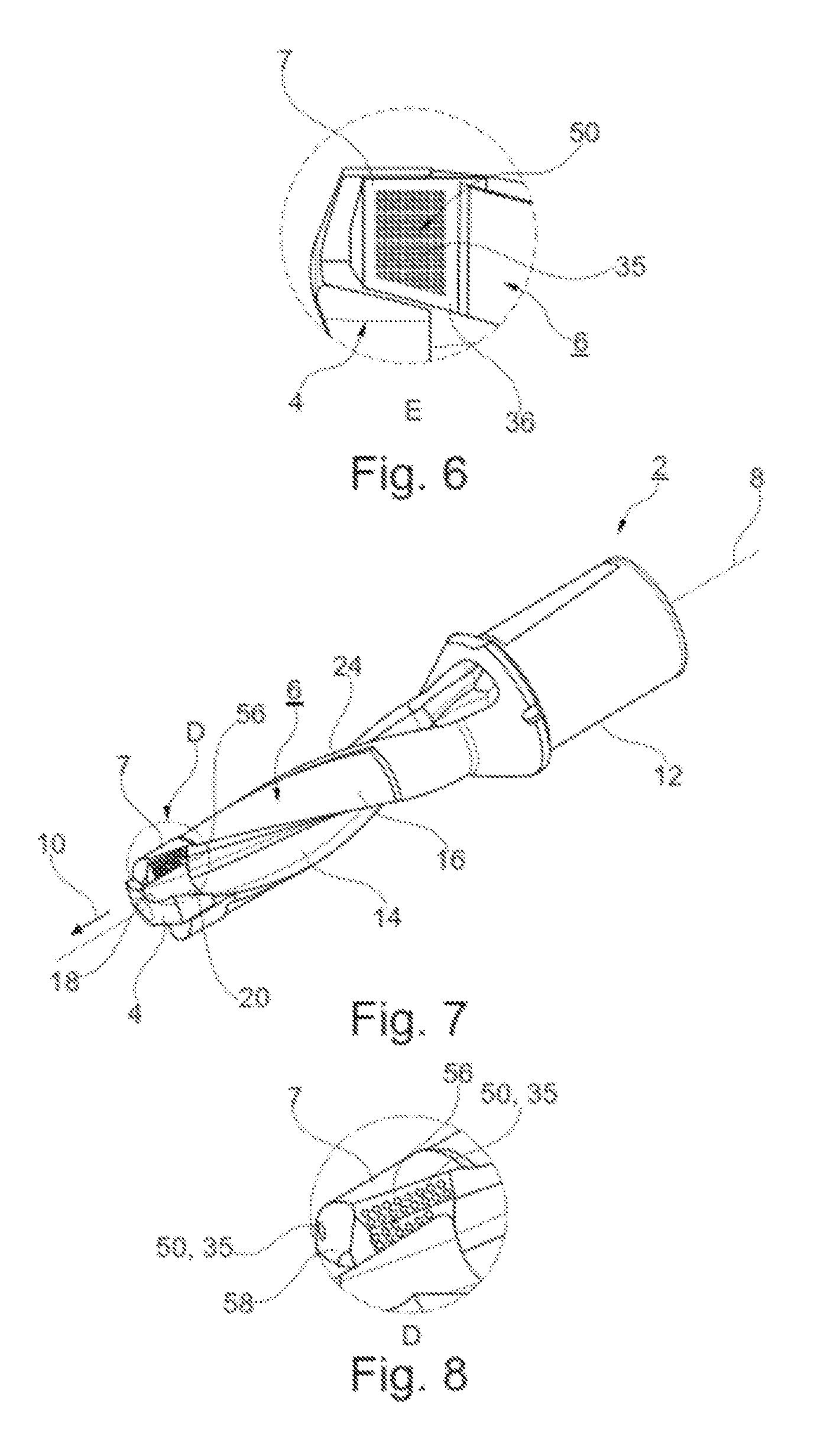
FIG. 6 shows an enlarged illustration of the area of the tool tip demarcated by a circle "E" in FIG. 1;
FIG. 7 shows a perspective illustration of a machining tool;
FIG. 8 shows an enlarged illustration of the area of the tool tip identified with a circle "D" in FIG. 7;
FIG. 9 shows a side view of a further machining tool; and
FIG. 10 shows a sectional view of the machining tool according to FIG. 9 along the intersecting line F-F.
Parts having the same effect are given the same reference numbers in the figures.
DETAILED DESCRIPTION OF THE INVENTION
The machining tool 2 illustrated in FIG. 1 is designed as a modular drill tool. It has a tool tip 4 in the form of a cutting element made of solid carbide or ceramic, which is reversibly and replaceably attached to the frontal end of a base body 6. In the present invention, a tool tip is generally understood to mean the frontal end area of the machining tool 2, i.e. a front end face area of the machining tool. In the exemplary embodiment according to FIG. 1, this is formed by the replaceable tool tip 4. In the case of a carrier tool having plate seats for attaching (indexable) inserts as cutting element, the area of the plate seat is understood to mean the tool tip. In a non-modular, one-piece tool, a front end area having an axial length, for example, in the range of a nominal diameter of the machining tool 2 is referred to as the tool tip. In the exemplary embodiment according to FIG. 1, the tool tip 4 is clamped as a reversibly replaceable insert between two clamping or retaining webs 7 of the base body 6.
The machining tool 2, and thus also the base body 6, as well as the tool tip 4 each extend in an axial direction 10 along a center axis 8 from a rearward end to a front end. At the same time, this center axis 8 defines a rotational axis around which the machining tool rotates in a rotational direction D during operation.
The base body 6 is in turn divided into a rear shaft part 12, with which the machining tool 2 is held clamped in a tensioning piece of a machine tool during operation. A cutting part 16 provided with chip flutes 14 adjoins the shaft part 12 in the axial direction 10. In the exemplary embodiment, the chip flutes 14 extend in a helical pattern. The end-face tool tip 4 has major cutting edges 18, each of which typically transitions into a minor cutting edge 20 on the circumferential side. These are continued in the cutting part 16.
A support bevel 24 adjoins the minor cutting edge 20 opposite the direction of rotation.
As is described below based on FIGS. 2 through 5, the base body 6 is a monolithic base body 6, which is formed not from a solid material, but rather--at least in axial sections--has a non-solid core structure 26. As FIG. 2 in particular illustrates, this core structure is designed as a circular structure in the shaft part 12, as seen in the cross-sectional view. The core structure 26 in this shaft part 12 is preferably designed to have a constant radius R.sub.1. It preferably extends at least nearly over the entire length of the shaft part 12 in the manner of a cylinder. This cylindrical core structure 26 is surrounded by an outer jacket 28, which, except for a flattening 30 introduced externally, is designed as an annular ring. The outer jacket 28 has a radius R.sub.2. The radius R.sub.1 of the core structure 26 is preferably around 50 to 90% of the outer radius R.sub.2. The core structure 26 has a core cross-sectional area A1, and the machining tool 2 has a total cross-sectional area A2. This area is defined by the area enclosed by the outer jacket 28, including the surface of the outer jacket 28.
At the rearward end of the shaft part 12, the same is optionally closed off with an end face plate formed of a solid material, i.e. the non-solid core structure 26 is formed only in the interior of the shaft part 12, without being visible from the rearward end face. A coolant transfer point is expediently formed and incorporated in this solid end face plate. In particular, a transverse groove having through-holes running to the core structure 26 is introduced.
In the exemplary embodiment, the core structure 26 is limited, in a similar manner, also in axial direction 10 in the end area of the shaft part 12 by a solid partition 32 through which at least one, or in the exemplary example two, cut-outs 34 penetrate. Alternatively, the core structure 26 also spans from the shaft part 12 into the cutting part 6 uninterrupted and without partition 32. A partition 32 is provided particularly in machining tools 2 without internal coolant supply. However, coolant supply is, in principle, made possible via the cut-outs 34 in the cutting part 16.
In the front area of the machining tool 2, i.e. in the area of the tool tip 4, at least one outlet point 35 for coolant or lubricant is provided. Multiple outlet points 35, which are oriented for example toward cutting areas, are preferably formed in a front end face or are also formed circumferentially. The outlet point 35 can be designed in a conventional manner as a borehole. However, it is likewise preferably created by means of the 3D printing method and is geometrically complex. The core structure 26 is preferably led to the outside to form the outlet point 35. In the exemplary embodiment illustrated in FIG. 1, an outlet point 35 is formed, for example, in a circumferential wall 36 in the area of the tool tip and particularly as a porous structure. The outlet point 35 in the exemplary embodiment is thus generally integrated into the retaining webs 7.
The core structure 26 continues into the cutting part 16 itself (FIG. 4). Owing to the chip flutes 14 and the thereby modified circumferential geometry of the base body 6, the cross-sectional geometry of the core structure 26 is adapted in particular such that it is enveloped entirely by roughly the same wall thickness of the outer jacket 28. In particular, the core structure 26 is designed to be elongated in the cutting part 16 and has a center area 37, which transitions into widened areas 38 at both ends. The outer edge of each said widened area has an arcuate contour, so that the widened area run concentrically to the circumferential line of the base body 6.
The core structure 26 is preferably homogeneous and even over its entire cross sectional area A1. Alternatively, additional supports can be provided in a manner not further illustrated here. Separate coolant channels are expediently not formed in the embodiment variants of FIG. 1.
According to a first embodiment variant, the core structure 26 is designed as a porous structure. According to a second embodiment variant illustrated in FIG. 5, the core structure 26, is, in contrast, designed as a grid-like, in particular honeycomb-shaped, structure. This structure has a plurality of individual channels 40 extending in the axial direction 10. Rectangular channels are schematically illustrated in FIG. 5. The individual channels 40 are each separated from one another by dividing walls 42. These dividing walls 42 preferably have only a low material thickness of, for example, below 0.3 and, particularly, below 0.15 mm. The individual channels 40 have a channel width W of usually below 0.5 mm.
The base body 6 is manufactured using what is referred to as a 3D printing method. In this method, a metal powder is worked successively and thus layer-by-layer by means of laser treatment according to the desired cross-sectional geometry of each layer and melted or sintered to form a cohesive, monolithic sub-body. In this process, each cross-sectional contour of each layer is predefined by the laser. With this 3D printing method, nearly any arbitrary as well as complex and, in particular, variable cross-sectional geometries can be realized. In particular, the core structure 26 described for FIGS. 2 through 5 and having the solid enveloping outer jacket 28 is realized using this method. The entire base body 6 is thus realized as a one-piece, monolithic body by means of this manufacturing method. This body can also undergo finishing work following the 3D printing process.
The base body 6 is preferably made of a tool steel according to DIN EN 10027, for example with a material number 1.2709 and/or 1.2344.
As is apparent in particular from FIG. 6 in conjunction with FIG. 1, the machining tool 2 in the area of the tool tip 4 has a cooling structure 4 which, in the embodiment variant according to FIG. 6, is designed as a planar, porous structure 50. This structure is led from inside to outside and forms the outlet point 35 in the circumferential wall 36 forming a drill back. This circumferential wall 36 thus forms an outer cladding. As FIG. 6 shows, the outlet point 35 extends over a large portion of the circumferential wall 36 and is planar. Viewed in the circumferential direction, the outlet point 35 thus extends for example over 40 to 80% of the available area between the minor cutting edge 20 and the succeeding chip flute 14. The circumferential wall 36 extends in the circumferential direction between these two elements. The porous structure 50 and thus the outlet point 35 also extend in the axial direction 10 over a large axial length of the circumferential wall 36, for example in turn over an axial length which corresponds to 0.25 to 4 times the nominal diameter of the machining tool 2.
Alternatively or additionally, a porous structure of this type having an outlet point 35 is also formed in the area of a chip flute wall 56 of the chip flute 14, as is illustrated in FIGS. 7 and 8. In this case as well, the outlet point 35 has a large-surface-area design. It extends preferably over 10 to 100% of the axial length of the tool tip 4 or is, for example, between 30 and 100% of the nominal diameter of the machining tool 2. If needed, the porous structure 50 can also be formed in the base body 6 in the chip flute wall 56 or on the circumferential wall 36. It is also apparent particularly from FIG. 8 that the outlet point 5 extends within the chip flute 14 over a comparatively large arc segment of the chip flute 14 and covers, for example, between 10 and 60% of the chip flute wall 56 in the circumferential direction of the chip flute 14. In the exemplary embodiment, the outlet point 35 is formed at the end of the chip flute 14 opposite the minor cutting edge 20, preferably in the retaining web 7.
Like in the exemplary embodiment shown in FIG. 1, in the exemplary embodiment shown in FIG. 7 the base body 6 has two opposite retaining webs 7 designed as clamping webs between which the tool tip 4 is clamped as cutting insert. The tool tip 4 is reversibly replaceable and is preferably held between the two retaining webs 57 solely by way of a clamping force. The cooling structure is generally integrated in particular in these retaining webs 7, and the at least one outlet point 35 is formed on these retaining webs 7.
Finally, FIG. 8 shows an additional third outlet point 35 in an end face 58, which allows coolant to exit immediately in the area near the major cutting edges. As FIG. 7, for example, shows, this end face 58 is slightly recessed compared to the tool tip 4 that is employed. In the exemplary embodiment, this end face 58 is formed in the lateral retaining webs 7.
The porous structure 50 is connected in particular to the porous core structure 26 via which it is supplied with coolant/lubricant during operation. The two structures 50, 26 expediently differ in terms of, for example, their porosity or also in terms of pore size, etc. Within the core structure 26, variation can also be provided by having different structures in the shaft area and in the cutting area.
FIGS. 9 and 10 finally illustrate a further exemplary embodiment in which, instead of the porous structure 50 as the cooling structure in the tool tip, multiple cooling channels 60 are formed, which are bent in the shape of a U in the area of the tool tip 4 and comprise a reversing segment 62. The cooling channel 60 thus comprises two channel segments 60a, 60b that run virtually antiparallel to one another. In the exemplary embodiment, the one channel segment 60 ends at a channel outlet 64 which is directed away from the front end of the machining tool 2. The other channel segment 60a is routed in the base body 6 to a coolant interface up to a rear end in the area of the shaft part 12, and in particular in a straight line or parallel or coaxial in relation to the center axis 8. The reversing segment 62 is in turn integrated into the respective retaining web 7. In the exemplary embodiments shown, conventional further cooling channels 66 are additionally provided (FIG. 9), which run in a helical pattern in the base body 6 and exit at the end face 58 or in the chip flute 14, for example.
The channel outlet 64 is preferably directed at a cutting element not illustrated in greater detail here. The cutting element is in particular a replaceable cutting plate. During operation, the coolant exiting the channel outlet 64 thus deliberately reaches the cutting element. Elongating an imaginary longitudinal axis of the channel segment 60b in front of the channel outlet 64 thus intersects in particular the edge of the cutting element.
As an alternative to this embodiment variant having the channel outlet 64, it is also possible to form a closed cooling circuit. For this purpose, the second channel segment 60b would then also be routed back to the rear coolant interface at the end portion of the shaft part 12. In this embodiment variant as well, the cooling channels 60 are designed with the reversing segment 62 in the respective clamping web of the base body 6.
* * * * *
D00000
D00001
D00002
D00003
XML
uspto.report is an independent third-party trademark research tool that is not affiliated, endorsed, or sponsored by the United States Patent and Trademark Office (USPTO) or any other governmental organization. The information provided by uspto.report is based on publicly available data at the time of writing and is intended for informational purposes only.
While we strive to provide accurate and up-to-date information, we do not guarantee the accuracy, completeness, reliability, or suitability of the information displayed on this site. The use of this site is at your own risk. Any reliance you place on such information is therefore strictly at your own risk.
All official trademark data, including owner information, should be verified by visiting the official USPTO website at www.uspto.gov. This site is not intended to replace professional legal advice and should not be used as a substitute for consulting with a legal professional who is knowledgeable about trademark law.