Prosthetic foot with enhanced stability and elastic energy return
Clausen , et al.
U.S. patent number 10,369,019 [Application Number 15/386,366] was granted by the patent office on 2019-08-06 for prosthetic foot with enhanced stability and elastic energy return. This patent grant is currently assigned to Ossur hf. The grantee listed for this patent is Ossur hf. Invention is credited to Bjarni Andresson, Arinbjorn Viggo Clausen, Vilhjalmur Freyr Jonsson, Christophe Lecomte.
View All Diagrams
| United States Patent | 10,369,019 |
| Clausen , et al. | August 6, 2019 |
Prosthetic foot with enhanced stability and elastic energy return
Abstract
A prosthetic foot comprises an attachment member and two or more flexible members. The attachment member can include a connector configured to connect the attachment member to a user or another prosthetic device. The two or more flexible members can be rotatably attached to the attachment member by rotatable joints such that the flexible members can both rotate and flex relative to the attachment member when the prosthetic foot contacts the ground.
| Inventors: | Clausen; Arinbjorn Viggo (Reykjavik, IS), Andresson; Bjarni (Seltjarnarnes, IS), Jonsson; Vilhjalmur Freyr (Reykjavik, IS), Lecomte; Christophe (Reykjavik, IS) | ||||||||||
|---|---|---|---|---|---|---|---|---|---|---|---|
| Applicant: |
|
||||||||||
| Assignee: | Ossur hf (Reykjavik,
IS) |
||||||||||
| Family ID: | 51388940 | ||||||||||
| Appl. No.: | 15/386,366 | ||||||||||
| Filed: | December 21, 2016 |
Prior Publication Data
| Document Identifier | Publication Date | |
|---|---|---|
| US 20170112640 A1 | Apr 27, 2017 | |
Related U.S. Patent Documents
| Application Number | Filing Date | Patent Number | Issue Date | ||
|---|---|---|---|---|---|
| 14188216 | Feb 24, 2014 | 9561118 | |||
| 61769405 | Feb 26, 2013 | ||||
| 61770212 | Feb 27, 2013 | ||||
| Current U.S. Class: | 1/1 |
| Current CPC Class: | A61F 2/6607 (20130101); A61F 2/66 (20130101); A61F 2/68 (20130101); A61F 2/70 (20130101); A61F 2002/74 (20130101); A61F 2002/6657 (20130101); A61F 2002/5006 (20130101); A61F 2002/5079 (20130101); A61F 2002/5033 (20130101); A61F 2002/6671 (20130101); A61F 2002/503 (20130101); A61F 2002/701 (20130101); A61F 2002/7615 (20130101); A61F 2002/6664 (20130101) |
| Current International Class: | A61F 2/50 (20060101); A61F 2/76 (20060101); A61F 2/68 (20060101); A61F 2/66 (20060101); A61F 2/70 (20060101); A61F 2/74 (20060101) |
References Cited [Referenced By]
U.S. Patent Documents
| 909859 | January 1909 | Apgar |
| 2475373 | July 1949 | Catranis |
| 2568051 | September 1951 | Catranis |
| 2619652 | December 1952 | Vesper |
| 2843853 | July 1958 | Mauch |
| 2859451 | November 1958 | Mauch |
| 3316558 | May 1967 | Mortensen |
| 3417409 | December 1968 | Prahl |
| 3501776 | March 1970 | Beeker et al. |
| 3589134 | June 1971 | Hackmann |
| 3659294 | May 1972 | Glabiszewski |
| 3701368 | October 1972 | Stern |
| 3791375 | February 1974 | Pfeifer |
| 3820168 | June 1974 | Horvath |
| 3866246 | February 1975 | Seamone et al. |
| 3871032 | March 1975 | Karas |
| 3953900 | May 1976 | Thompson |
| 3995324 | December 1976 | Burch |
| 4005496 | February 1977 | Wilkes |
| 4023215 | May 1977 | Moore |
| 4030141 | June 1977 | Graupe |
| 4064569 | December 1977 | Campbell |
| 4065815 | January 1978 | Sen-Jung |
| 4100918 | July 1978 | Glancy |
| 4179759 | December 1979 | Smith |
| 4209860 | July 1980 | Graupe |
| 4212087 | July 1980 | Mortensen |
| 4310932 | January 1982 | Nader et al. |
| 4314379 | February 1982 | Tanie et al. |
| 4354676 | October 1982 | Ariel |
| 4370977 | February 1983 | Mauldin et al. |
| 4386891 | June 1983 | Riefel et al. |
| 4387472 | June 1983 | Wilson |
| 4433679 | February 1984 | Mauldin et al. |
| 4458367 | July 1984 | May |
| 4488320 | December 1984 | Wilson |
| 4518307 | May 1985 | Bloch |
| 4521924 | June 1985 | Jacobsen et al. |
| 4556956 | December 1985 | Dickenson et al. |
| 4558704 | December 1985 | Petrofsky |
| 4569352 | February 1986 | Petrofsky et al. |
| 4578083 | March 1986 | Williams |
| 4579558 | April 1986 | Ramer |
| 4600357 | July 1986 | Coules |
| 4602619 | July 1986 | Wolf et al. |
| 4617920 | October 1986 | Carsalade |
| 4649934 | March 1987 | Fraser et al. |
| 4652266 | March 1987 | Truesdell |
| 4657000 | April 1987 | Hepburn |
| 4657470 | April 1987 | Clarke et al. |
| 4685926 | August 1987 | Haupt |
| 4685927 | August 1987 | Haupt |
| 4711242 | December 1987 | Petrofsky |
| 4711450 | December 1987 | McArthur |
| 4726404 | February 1988 | Haber et al. |
| 4730625 | March 1988 | Fraser et al. |
| 4760850 | August 1988 | Phillips et al. |
| 4770662 | September 1988 | Giampapa |
| 4776326 | October 1988 | Young et al. |
| 4776852 | October 1988 | Rubic |
| 4790522 | December 1988 | Drutchas |
| 4795474 | January 1989 | Horvath |
| 4805455 | February 1989 | DelGiorno et al. |
| 4808187 | February 1989 | Patterson et al. |
| 4814661 | March 1989 | Ratzlaff et al. |
| 4838251 | June 1989 | Chignon et al. |
| 4843921 | July 1989 | Kremer |
| 4854428 | August 1989 | Horvath |
| 4865024 | September 1989 | Hensley et al. |
| 4872803 | October 1989 | Asakawa |
| 4876944 | October 1989 | Wilson et al. |
| 4878913 | November 1989 | Aebischer et al. |
| 4892554 | January 1990 | Robinson |
| 4893648 | January 1990 | Horvath |
| 4919418 | April 1990 | Miller |
| 4928676 | May 1990 | Pansiera |
| 4944755 | July 1990 | Hennequin et al. |
| 4958705 | September 1990 | Horvath |
| 4989161 | January 1991 | Oaki |
| 4994086 | February 1991 | Edwards |
| 5012591 | May 1991 | Asakawa |
| 5020790 | June 1991 | Beard et al. |
| 5033291 | July 1991 | Podoloff et al. |
| 5044360 | September 1991 | Janke |
| 5062673 | November 1991 | Mimura |
| 5062856 | November 1991 | Sawamura et al. |
| 5062857 | November 1991 | Berringer |
| 5086785 | February 1992 | Gentile et al. |
| 5092902 | March 1992 | Adams et al. |
| 5101472 | March 1992 | Repperger |
| 5112296 | May 1992 | Beard et al. |
| 5112356 | May 1992 | Harris et al. |
| 5139525 | August 1992 | Kristinsson |
| 5153496 | October 1992 | LaForge |
| 5156630 | October 1992 | Rappoport et al. |
| 5174168 | December 1992 | Takagi et al. |
| 5181931 | January 1993 | Van de Veen |
| 5197488 | March 1993 | Kovacevic |
| 5201772 | April 1993 | Maxwell |
| 5217500 | June 1993 | Phillips |
| 5219365 | June 1993 | Sabolich |
| 5230672 | July 1993 | Brown et al. |
| 5246465 | September 1993 | Rincoe et al. |
| 5252102 | October 1993 | Singer et al. |
| 5252901 | October 1993 | Ozawa et al. |
| 5253656 | October 1993 | Rincoe et al. |
| 5265890 | November 1993 | Balsells |
| 5277281 | January 1994 | Carlson et al. |
| 5282460 | February 1994 | Boldt |
| 5284330 | February 1994 | Carlson et al. |
| 5314498 | May 1994 | Gramnaes |
| 5323650 | June 1994 | Fullen et al. |
| 5327790 | July 1994 | Levin et al. |
| 5336269 | August 1994 | Smits |
| 5357696 | October 1994 | Gray et al. |
| 5376128 | December 1994 | Bozeman, Jr. |
| 5376133 | December 1994 | Gramnaes |
| 5376137 | December 1994 | Shorter et al. |
| 5376138 | December 1994 | Bouchard et al. |
| 5376141 | December 1994 | Phillips |
| 5382373 | January 1995 | Carlson et al. |
| 5383939 | January 1995 | James |
| 5394132 | February 1995 | Poil |
| 5397287 | March 1995 | Lindfors |
| 5405407 | April 1995 | Kodama et al. |
| 5405409 | April 1995 | Knoth |
| 5405410 | April 1995 | Arbogast et al. |
| 5405510 | April 1995 | Betts |
| 5408873 | April 1995 | Schmidt et al. |
| 5413611 | May 1995 | Haslam, II et al. |
| 5422558 | June 1995 | Stewart |
| 5425780 | June 1995 | Flatt et al. |
| 5430643 | July 1995 | Seraji |
| 5437611 | August 1995 | Stern |
| 5443521 | August 1995 | Knoth et al. |
| 5443524 | August 1995 | Sawamura et al. |
| 5443528 | August 1995 | Allen |
| 5455497 | October 1995 | Hirose et al. |
| 5472412 | December 1995 | Knoth |
| 5476441 | December 1995 | Durfee et al. |
| 5484389 | January 1996 | Stark et al. |
| 5504415 | April 1996 | Podrazhansky et al. |
| D372536 | August 1996 | Grifka |
| 5545232 | August 1996 | Van de Veen |
| 5545233 | August 1996 | Fitzlaff |
| 5551525 | September 1996 | Pack et al. |
| 5563458 | October 1996 | Ericson |
| 5566479 | October 1996 | Gray et al. |
| 5571205 | November 1996 | James |
| 5571210 | November 1996 | Lindh |
| 5571212 | November 1996 | Cornelius |
| 5571213 | November 1996 | Allen |
| 5583476 | December 1996 | Langford et al. |
| 5586557 | December 1996 | Nelson et al. |
| 5624389 | April 1997 | Zepf |
| 5642096 | June 1997 | Leyerer et al. |
| 5645590 | July 1997 | Van de Veen |
| 5645752 | July 1997 | Weiss et al. |
| 5650704 | July 1997 | Pratt et al. |
| 5656915 | August 1997 | Eaves |
| D383542 | September 1997 | Wellershaus et al. |
| 5662693 | September 1997 | Johnson et al. |
| 5670077 | September 1997 | Carlson et al. |
| 5678448 | October 1997 | Fullen et al. |
| 5683615 | November 1997 | Munoz |
| 5695527 | December 1997 | Allen |
| 5704945 | January 1998 | Wagner et al. |
| 5704946 | January 1998 | Greene |
| 5711746 | January 1998 | Carlson |
| 5728170 | March 1998 | Becker et al. |
| 5728174 | March 1998 | Fitzlaff |
| 5746774 | May 1998 | Kramer |
| 5749533 | May 1998 | Daniels |
| 5755812 | May 1998 | Becker et al. |
| 5755813 | May 1998 | Krukenberg |
| 5779735 | July 1998 | Molino |
| 5800561 | September 1998 | Rodriquez |
| 5800568 | September 1998 | Atkinson et al. |
| 5810752 | September 1998 | Grifka |
| 5823309 | October 1998 | Gopalswamy et al. |
| D402368 | December 1998 | Holzapfel |
| 5842547 | December 1998 | Carlson et al. |
| D407490 | March 1999 | Zepf et al. |
| 5878851 | March 1999 | Carlson et al. |
| 5888212 | March 1999 | Petrofsky et al. |
| 5888213 | March 1999 | Sears et al. |
| 5888236 | March 1999 | Van de Veen |
| 5888239 | March 1999 | Wellershaus et al. |
| 5888246 | March 1999 | Gow |
| 5893891 | April 1999 | Zahedi |
| 5895430 | April 1999 | O'Connor |
| 5899869 | May 1999 | Barrack, Jr. et al. |
| 5900184 | May 1999 | Weiss et al. |
| 5906767 | May 1999 | Karol et al. |
| 5919149 | July 1999 | Allum |
| 5929332 | July 1999 | Brown |
| 5941913 | August 1999 | Woolnough et al. |
| 5947238 | September 1999 | Jolly et al. |
| 5948021 | September 1999 | Radcliffe |
| 5955667 | September 1999 | Fyfe |
| 5957981 | September 1999 | Gramnaes |
| 5960918 | October 1999 | Moser et al. |
| 5967273 | October 1999 | Hampton |
| 5972035 | October 1999 | Blatchford |
| 5982156 | November 1999 | Weimer et al. |
| 5984972 | November 1999 | Huston et al. |
| 5998930 | December 1999 | Upadhyay et al. |
| 6006412 | December 1999 | Bergmann et al. |
| 6007582 | December 1999 | May |
| RE36521 | January 2000 | Hiemisch |
| 6039091 | March 2000 | Rodgers et al. |
| 6061577 | May 2000 | Andrieu et al. |
| 6080123 | June 2000 | Pansiera |
| 6086616 | July 2000 | Okuda et al. |
| 6091977 | July 2000 | Tarjan et al. |
| 6093162 | July 2000 | Fairleigh et al. |
| 6095486 | August 2000 | Ivers et al. |
| 6113642 | September 2000 | Petrofsky et al. |
| 6117177 | September 2000 | Chen et al. |
| 6122960 | September 2000 | Hutchings et al. |
| 6129690 | October 2000 | Hamlin et al. |
| 6129766 | October 2000 | Johnson et al. |
| 6139586 | October 2000 | Wagner et al. |
| 6151624 | November 2000 | Teare et al. |
| 6164967 | December 2000 | Sale |
| 6165226 | December 2000 | Wagner |
| 6168634 | January 2001 | Schmitz |
| 6183425 | February 2001 | Whalen et al. |
| 6185614 | February 2001 | Cuomo et al. |
| 6187051 | February 2001 | Gerad van de Veen |
| 6187052 | February 2001 | Molino et al. |
| D439339 | March 2001 | Sawatzki |
| 6195921 | March 2001 | Truong |
| 6206932 | March 2001 | Johnson |
| 6206933 | March 2001 | Shorter et al. |
| 6206934 | March 2001 | Phillips |
| 6241775 | June 2001 | Blatchford |
| 6241776 | June 2001 | Christensen |
| D446304 | August 2001 | Sawatzki |
| 6301964 | October 2001 | Fyfe et al. |
| 6342076 | January 2002 | Lundborg |
| 6350286 | February 2002 | Atkinson et al. |
| 6352144 | March 2002 | Brooks |
| 6361570 | March 2002 | Gow |
| 6373152 | April 2002 | Wang et al. |
| 6378190 | April 2002 | Akeel |
| 6379393 | April 2002 | Mavroidis et al. |
| 6395193 | May 2002 | Kintz et al. |
| 6409695 | June 2002 | Connelly |
| 6423098 | July 2002 | Biedermann |
| 6425925 | July 2002 | Grundei |
| 6430843 | August 2002 | Potter et al. |
| 6436149 | August 2002 | Rincoe |
| 6443993 | September 2002 | Koniuk |
| 6443995 | September 2002 | Townsend et al. |
| 6451481 | September 2002 | Lee et al. |
| 6485519 | November 2002 | Meyers et al. |
| 6494039 | December 2002 | Pratt et al. |
| 6500210 | December 2002 | Sabolich et al. |
| 6513381 | February 2003 | Fyfe et al. |
| 6517585 | February 2003 | Zahedi et al. |
| 6517828 | February 2003 | Fyfe et al. |
| 6517858 | February 2003 | Le Moel et al. |
| 6522266 | February 2003 | Soehren et al. |
| 6537322 | March 2003 | Johnson et al. |
| 6543987 | April 2003 | Ehrat |
| 6562075 | May 2003 | Townsend et al. |
| 6574655 | June 2003 | Libert et al. |
| 6587728 | July 2003 | Fang et al. |
| 6589287 | July 2003 | Lundborg |
| 6599439 | July 2003 | Iregar et al. |
| 6602295 | August 2003 | Doddroe et al. |
| 6610101 | August 2003 | Herr et al. |
| 6613097 | September 2003 | Cooper |
| 6645252 | November 2003 | Asai et al. |
| 6663673 | December 2003 | Christensen |
| 6671531 | December 2003 | Al-Ali et al. |
| 6679920 | January 2004 | Biedermann et al. |
| 6695885 | February 2004 | Schulman et al. |
| 6704024 | March 2004 | Robotham et al. |
| 6704582 | March 2004 | Le-Faucheur et al. |
| 6708103 | March 2004 | Herr et al. |
| 6719806 | April 2004 | Zahedi et al. |
| 6719807 | April 2004 | Harris |
| 6733180 | May 2004 | Nakamura |
| 6740123 | May 2004 | Davalli et al. |
| 6740125 | May 2004 | Mosler |
| 6743260 | June 2004 | Townsend et al. |
| 6755870 | June 2004 | Biedermann et al. |
| 6761743 | July 2004 | Johnson |
| 6764520 | July 2004 | Deffenbaugh et al. |
| 6764521 | July 2004 | Molino et al. |
| 6767370 | July 2004 | Mosler et al. |
| 6770045 | August 2004 | Naft et al. |
| 6780343 | August 2004 | Hata et al. |
| 6805677 | October 2004 | Simmons |
| 6811571 | November 2004 | Phillips |
| 6813582 | November 2004 | Levi et al. |
| 6824569 | November 2004 | Okediji |
| D499487 | December 2004 | Bedard et al. |
| D501925 | February 2005 | Bedard et al. |
| 6855170 | February 2005 | Gramnas |
| 6863695 | March 2005 | Doddroe et al. |
| 6875241 | April 2005 | Christensen |
| 6876135 | April 2005 | Pelrine et al. |
| 6908488 | June 2005 | Paasivaara et al. |
| 6910331 | June 2005 | Asai et al. |
| 6918308 | July 2005 | Biedermann |
| 6955692 | October 2005 | Grundei |
| 6966882 | November 2005 | Horst |
| 6966933 | November 2005 | Christensen |
| 6972043 | December 2005 | Biedermann |
| 7025792 | April 2006 | Collier |
| 7029500 | April 2006 | Martin |
| 7042197 | May 2006 | Turner et al. |
| 7063727 | June 2006 | Phillips et al. |
| 7066896 | June 2006 | Kiselik |
| 7066964 | June 2006 | Wild |
| 7101487 | September 2006 | Hsu et al. |
| 7112938 | September 2006 | Takenaka et al. |
| 7118601 | October 2006 | Yasui |
| 7131998 | November 2006 | Pasolini |
| 7137998 | November 2006 | Bedard et al. |
| 7147667 | December 2006 | Bedard et al. |
| 7150762 | December 2006 | Caspers |
| 7164967 | January 2007 | Etienne-Cummings et al. |
| 7172630 | February 2007 | Christensen |
| 7182738 | February 2007 | Bonutti et al. |
| 7198071 | April 2007 | Bisbee, III et al. |
| 7209788 | April 2007 | Nicolelis et al. |
| 7211115 | May 2007 | Townsend et al. |
| 7226485 | June 2007 | Townsend et al. |
| 7279009 | October 2007 | Herr et al. |
| 7295892 | November 2007 | Herr et al. |
| 7300240 | November 2007 | Brogardh |
| 7308333 | December 2007 | Kern et al. |
| 7313463 | December 2007 | Herr et al. |
| 7314490 | January 2008 | Bedard et al. |
| 7364593 | April 2008 | Townsend et al. |
| 7374578 | May 2008 | Townsend et al. |
| 7381192 | June 2008 | Brodard et al. |
| 7396337 | July 2008 | McBean et al. |
| 7410338 | August 2008 | Schiele et al. |
| 7410471 | August 2008 | Campbell et al. |
| 7410472 | August 2008 | Yakimovich et al. |
| 7410503 | August 2008 | Townsend et al. |
| 7419509 | September 2008 | Christensen |
| 7429272 | September 2008 | Townsend et al. |
| 7455696 | November 2008 | Bisbee, III et al. |
| 7462201 | December 2008 | Christensen |
| 7485152 | February 2009 | Haynes et al. |
| 7503900 | March 2009 | Goswami |
| 7507259 | March 2009 | Townsend et al. |
| 7520904 | April 2009 | Christensen |
| 7531006 | May 2009 | Clausen et al. |
| 7552664 | June 2009 | Bulatowicz |
| 7572299 | August 2009 | Christensen |
| 7575602 | August 2009 | Amirouche et al. |
| 7578799 | August 2009 | Thorsteinsson et al. |
| 7578852 | August 2009 | Townsend et al. |
| 7588604 | September 2009 | Okuda |
| 7611543 | November 2009 | Townsend et al. |
| 7637957 | December 2009 | Ragnarsdottir et al. |
| 7637959 | December 2009 | Clausen et al. |
| 7641700 | January 2010 | Yasui |
| 7655050 | February 2010 | Palmer et al. |
| 7686848 | March 2010 | Christensen |
| 7691154 | April 2010 | Asgeirsson et al. |
| 7708784 | May 2010 | Townsend et al. |
| 7736394 | June 2010 | Bedard et al. |
| 7763082 | July 2010 | Curtis |
| 7766974 | August 2010 | Curtis |
| 7794505 | September 2010 | Clausen et al. |
| 7799091 | September 2010 | Herr et al. |
| 7811333 | October 2010 | Jonsson et al. |
| 7811334 | October 2010 | Ragnarsdottir et al. |
| 7815689 | October 2010 | Bedard et al. |
| 7824446 | November 2010 | Christensen |
| 7862620 | January 2011 | Clausen et al. |
| 7867284 | January 2011 | Bedard et al. |
| 7867285 | January 2011 | Clausen et al. |
| 7883546 | February 2011 | Kazerooni et al. |
| 7918808 | April 2011 | Simmons |
| 7942935 | May 2011 | Iversen et al. |
| 7951101 | May 2011 | Pusch |
| 7955398 | June 2011 | Bedard et al. |
| 7955399 | June 2011 | Townsend et al. |
| 7985265 | July 2011 | Moser et al. |
| 7992849 | August 2011 | Sugar et al. |
| 8007544 | August 2011 | Jonsson et al. |
| 8034121 | October 2011 | Christensen |
| 8048007 | November 2011 | Roy |
| 8048172 | November 2011 | Jonsson et al. |
| 8057550 | November 2011 | Clausen |
| 8070829 | December 2011 | Townsend et al. |
| 8075633 | December 2011 | Herr et al. |
| 8083807 | December 2011 | Auberger et al. |
| 8087498 | January 2012 | Dupuis et al. |
| 8109890 | February 2012 | Kamiar et al. |
| 8118879 | February 2012 | Wilson |
| 8122772 | February 2012 | Clausen et al. |
| 8142370 | March 2012 | Weinberg et al. |
| 8211042 | July 2012 | Gilbert et al. |
| 8231687 | July 2012 | Bedard et al. |
| 8236062 | August 2012 | Townsend |
| 8287477 | October 2012 | Herr et al. |
| 8317876 | November 2012 | Mosler |
| 8317877 | November 2012 | Doddroe et al. |
| 8323354 | December 2012 | Bedard et al. |
| 8366788 | February 2013 | Moser et al. |
| 8366790 | February 2013 | Curtis |
| 8376971 | February 2013 | Herr et al. |
| 8403997 | March 2013 | Sykes et al. |
| 8435309 | May 2013 | Gilbert et al. |
| 8500823 | August 2013 | Herr et al. |
| 8512415 | August 2013 | Herr et al. |
| 8551184 | October 2013 | Herr |
| 8574314 | November 2013 | Townsend |
| 7431737 | December 2013 | Ragnarsdottir et al. |
| 8601897 | December 2013 | Lauzier et al. |
| 8617254 | December 2013 | Bisbee, III et al. |
| 8657886 | February 2014 | Clausen et al. |
| 8702811 | April 2014 | Ragnarsdottir et al. |
| 7896927 | May 2014 | Clausen et al. |
| 8790282 | July 2014 | Jung et al. |
| 8801802 | August 2014 | Oddsson et al. |
| 8814949 | August 2014 | Gramnaes |
| 8852292 | October 2014 | Ragnarsdottir et al. |
| 8870967 | October 2014 | Herr et al. |
| 8986397 | March 2015 | Bedard et al. |
| 9044346 | June 2015 | Langlois et al. |
| 9060884 | June 2015 | Langlois |
| 9066819 | June 2015 | Gramnaes |
| 9078774 | July 2015 | Jonsson et al. |
| 9114029 | August 2015 | sgeirsson |
| 9271851 | March 2016 | Claussen et al. |
| 9289316 | March 2016 | Ward et al. |
| 9345591 | May 2016 | Bisbee, III et al. |
| 9358137 | June 2016 | Bedard et al. |
| 9459698 | October 2016 | Lee |
| 9462966 | October 2016 | Clausen et al. |
| 9526635 | December 2016 | Gilbert et al. |
| 9526636 | December 2016 | Bedard et al. |
| 9532877 | January 2017 | Holgate |
| 9561118 | February 2017 | Clausen et al. |
| 9604368 | March 2017 | Holgate |
| 9622884 | April 2017 | Holgate et al. |
| 9649206 | May 2017 | Bedard |
| 9707104 | July 2017 | Clausen |
| 9717606 | August 2017 | Gramnaes |
| 9808357 | November 2017 | Langlois |
| 9895240 | February 2018 | Langlois et al. |
| 2002/0007690 | January 2002 | Song et al. |
| 2002/0079857 | June 2002 | Ishii et al. |
| 2002/0087216 | July 2002 | Atkinson et al. |
| 2002/0143408 | October 2002 | Townsend et al. |
| 2003/0005786 | January 2003 | Stuart et al. |
| 2003/0019700 | January 2003 | Wittig |
| 2003/0149600 | August 2003 | Williams |
| 2004/0064195 | April 2004 | Herr |
| 2004/0078299 | April 2004 | Down-Logan et al. |
| 2004/0083007 | April 2004 | Molino et al. |
| 2004/0153484 | August 2004 | Unno |
| 2004/0193286 | September 2004 | Grundei |
| 2005/0033451 | February 2005 | Aigner et al. |
| 2005/0038525 | February 2005 | Doddroe et al. |
| 2005/0049719 | March 2005 | Wilson |
| 2005/0049721 | March 2005 | Sulprizio |
| 2005/0070834 | March 2005 | Herr et al. |
| 2005/0071017 | March 2005 | Lecomte et al. |
| 2005/0107889 | May 2005 | Bedard et al. |
| 2005/0113973 | May 2005 | Endo et al. |
| 2005/0137717 | June 2005 | Gramnaes |
| 2005/0166685 | August 2005 | Boiten |
| 2005/0192677 | September 2005 | Ragnarsdottir et al. |
| 2005/0203640 | September 2005 | Christensen |
| 2005/0216097 | September 2005 | Rifkin |
| 2005/0283257 | December 2005 | Bisbee et al. |
| 2006/0025959 | February 2006 | Gomez et al. |
| 2006/0030950 | February 2006 | Townsend et al. |
| 2006/0069336 | March 2006 | Krebs et al. |
| 2006/0136072 | June 2006 | Bisbee et al. |
| 2006/0184252 | August 2006 | Oddsson et al. |
| 2006/0184280 | August 2006 | Oddsson et al. |
| 2006/0189899 | August 2006 | Flaherty et al. |
| 2006/0212131 | September 2006 | Curtis |
| 2006/0235545 | October 2006 | Habecker |
| 2006/0249315 | November 2006 | Herr et al. |
| 2006/0259153 | November 2006 | Harn et al. |
| 2006/0260620 | November 2006 | Kazerooni et al. |
| 2007/0027557 | February 2007 | Jonsson et al. |
| 2007/0043449 | February 2007 | Herr et al. |
| 2007/0050047 | March 2007 | Ragnarsdottir et al. |
| 2007/0061016 | March 2007 | Kuo |
| 2007/0123997 | May 2007 | Herr et al. |
| 2007/0129653 | June 2007 | Sugar et al. |
| 2007/0162152 | July 2007 | Herr et al. |
| 2007/0213841 | September 2007 | Townsend et al. |
| 2008/0004718 | January 2008 | Mosler |
| 2008/0046096 | February 2008 | Bedard et al. |
| 2008/0058668 | March 2008 | Seyed Momen et al. |
| 2008/0141813 | June 2008 | Ehrat |
| 2008/0262635 | October 2008 | Moser et al. |
| 2008/0306612 | December 2008 | Mosler |
| 2009/0012630 | January 2009 | Mosler et al. |
| 2009/0030530 | January 2009 | Martin |
| 2009/0088912 | April 2009 | Rajaraman |
| 2009/0192625 | July 2009 | Boiten |
| 2009/0204230 | August 2009 | Kaltenborn et al. |
| 2009/0204231 | August 2009 | Bonacini |
| 2009/0265018 | October 2009 | Goldfarb et al. |
| 2009/0299489 | December 2009 | Gramnaes |
| 2010/0023133 | January 2010 | Fairbanks et al. |
| 2010/0023135 | January 2010 | Rubie et al. |
| 2010/0030343 | February 2010 | Hansen et al. |
| 2010/0042228 | February 2010 | Doddroe et al. |
| 2010/0094431 | April 2010 | Albrecht-Laatsch |
| 2010/0113980 | May 2010 | Herr et al. |
| 2010/0114329 | May 2010 | Casler et al. |
| 2010/0131101 | May 2010 | Engeberg et al. |
| 2010/0161077 | June 2010 | Boone et al. |
| 2010/0179668 | July 2010 | Herr et al. |
| 2010/0185301 | July 2010 | Hansen et al. |
| 2010/0241242 | September 2010 | Herr et al. |
| 2010/0262260 | October 2010 | Bedard et al. |
| 2010/0275718 | November 2010 | Stuart et al. |
| 2010/0305716 | December 2010 | Pusch et al. |
| 2010/0324456 | December 2010 | Jonsson et al. |
| 2010/0324699 | December 2010 | Herr et al. |
| 2010/0332002 | December 2010 | Nelson |
| 2011/0015761 | January 2011 | Celebi et al. |
| 2011/0106274 | May 2011 | Ragnarsdottir et al. |
| 2011/0125290 | May 2011 | Langlois |
| 2011/0130847 | June 2011 | Bedard et al. |
| 2011/0132131 | June 2011 | Worz |
| 2011/0137429 | June 2011 | Bedard et al. |
| 2011/0166674 | July 2011 | Montmartin |
| 2011/0196509 | August 2011 | Jansent et al. |
| 2011/0202144 | August 2011 | Palmer et al. |
| 2011/0208322 | August 2011 | Rifkin et al. |
| 2011/0224804 | September 2011 | Clausen et al. |
| 2011/0257764 | October 2011 | Herr |
| 2011/0295384 | December 2011 | Herr et al. |
| 2011/0295385 | December 2011 | Herr et al. |
| 2012/0016492 | January 2012 | Clausen |
| 2012/0016493 | January 2012 | Hansen |
| 2012/0078415 | March 2012 | Kubo et al. |
| 2012/0130508 | May 2012 | Harris et al. |
| 2012/0191221 | July 2012 | Bedard et al. |
| 2012/0203359 | August 2012 | Schimmels et al. |
| 2012/0209405 | August 2012 | Herr et al. |
| 2012/0226364 | September 2012 | Kampas et al. |
| 2012/0283845 | November 2012 | Herr et al. |
| 2012/0330439 | December 2012 | Goldfarb et al. |
| 2013/0035769 | February 2013 | Bedard et al. |
| 2013/0118287 | May 2013 | Holgate |
| 2013/0142608 | June 2013 | Zhang et al. |
| 2013/0144402 | June 2013 | Clausen et al. |
| 2013/0173022 | July 2013 | Arabian et al. |
| 2013/0204395 | August 2013 | Gramnaes |
| 2013/0218295 | August 2013 | Holgate et al. |
| 2013/0218298 | August 2013 | Mosler |
| 2013/0268093 | October 2013 | Gilbert et al. |
| 2013/0297041 | November 2013 | Bedard et al. |
| 2014/0039642 | February 2014 | Nijiman et al. |
| 2014/0074243 | March 2014 | Holgate |
| 2014/0081424 | March 2014 | Herr et al. |
| 2014/0114437 | April 2014 | Herr et al. |
| 2014/0121782 | May 2014 | Herr et al. |
| 2014/0156025 | June 2014 | Bisbee, III et al. |
| 2014/0200680 | July 2014 | Holgate et al. |
| 2014/0277586 | September 2014 | Clausen |
| 2014/0330393 | November 2014 | Ward et al. |
| 2015/0032225 | January 2015 | Oddsson et al. |
| 2015/0073566 | March 2015 | Ragnarsdottir et al. |
| 2015/0164661 | June 2015 | Ragnarsdottir et al. |
| 2015/0223952 | August 2015 | Langlois et al. |
| 2015/0265429 | September 2015 | Jonsson et al. |
| 2015/0297368 | October 2015 | Langlois |
| 2015/0320573 | November 2015 | Gramnaes |
| 2015/0328020 | November 2015 | Clausen et al. |
| 2016/0302956 | October 2016 | Gilbert et al. |
| 2017/0304083 | October 2017 | Clausen |
| 2018/0125678 | May 2018 | Langlois |
| 2 405 356 | Oct 2001 | CA | |||
| 2 494 365 | Mar 2004 | CA | |||
| 2 543 061 | Jun 2005 | CA | |||
| 543 277 | Dec 1973 | CH | |||
| 2043873 | Sep 1989 | CN | |||
| 1215614 | May 1999 | CN | |||
| 2400072 | Oct 2000 | CN | |||
| 2776340 | May 2006 | CN | |||
| 1929797 | Mar 2007 | CN | |||
| 35 43 291 | Jun 1987 | DE | |||
| 39 23 056 | Jan 1991 | DE | |||
| 39 23 057 | Jan 1991 | DE | |||
| 43 05 213 | Aug 1993 | DE | |||
| 42 29 330 | Mar 1994 | DE | |||
| 0 358 056 | Mar 1990 | EP | |||
| 0 380 060 | Aug 1990 | EP | |||
| 0 654 254 | May 1995 | EP | |||
| 0 902 547 | Mar 1999 | EP | |||
| 1 125 825 | Jan 2001 | EP | |||
| 1 107 420 | Jun 2001 | EP | |||
| 1 166 726 | Jan 2002 | EP | |||
| 1 169 982 | Jan 2002 | EP | |||
| 1 410 780 | Apr 2004 | EP | |||
| 1 442 704 | Aug 2004 | EP | |||
| 1 547 567 | Jun 2005 | EP | |||
| 1 792 597 | Jun 2007 | EP | |||
| 2 564 817 | Mar 2013 | EP | |||
| 2 702 963 | Mar 2014 | EP | |||
| 2 293 185 | Jul 1976 | FR | |||
| 2 623 086 | May 1989 | FR | |||
| 2 816 463 | May 2002 | FR | |||
| 2 201 260 | Aug 1988 | GB | |||
| 2 228 201 | Aug 1990 | GB | |||
| 2 244 006 | Nov 1991 | GB | |||
| 2 260 495 | Apr 1993 | GB | |||
| 2 301 776 | Dec 1996 | GB | |||
| 2 302 949 | Feb 1997 | GB | |||
| 2 338 653 | Dec 1999 | GB | |||
| 2 343 848 | May 2000 | GB | |||
| 2 367 753 | Apr 2002 | GB | |||
| 59-032453 | Feb 1984 | JP | |||
| 59-071747 | Apr 1984 | JP | |||
| 59-088147 | May 1984 | JP | |||
| 59-189843 | Oct 1984 | JP | |||
| 60-081530 | May 1985 | JP | |||
| 60-177102 | Sep 1985 | JP | |||
| 01-244748 | Sep 1989 | JP | |||
| 03-181633 | Aug 1991 | JP | |||
| 04-078337 | Mar 1992 | JP | |||
| 05-123348 | May 1993 | JP | |||
| 05-161668 | Jun 1993 | JP | |||
| 07-024766 | Jan 1995 | JP | |||
| 11-000345 | Jan 1999 | JP | |||
| 11-056885 | Mar 1999 | JP | |||
| 11-215793 | Aug 1999 | JP | |||
| 2001-277175 | Oct 2001 | JP | |||
| 2002-191654 | Jul 2002 | JP | |||
| 2005-500 | Jan 2005 | JP | |||
| 2005-536317 | Dec 2005 | JP | |||
| 2009-153660 | Jul 2009 | JP | |||
| 2002-0041137 | Jun 2002 | KR | |||
| 1447366 | Dec 1988 | SU | |||
| 1731210 | May 1992 | SU | |||
| WO 94/006374 | Mar 1994 | WO | |||
| WO 94/009727 | May 1994 | WO | |||
| WO 95/026171 | Oct 1995 | WO | |||
| WO 96/039110 | Dec 1996 | WO | |||
| WO 96/041599 | Dec 1996 | WO | |||
| WO 97/000661 | Jan 1997 | WO | |||
| WO 97/027822 | Aug 1997 | WO | |||
| WO 98/038951 | Sep 1998 | WO | |||
| WO 99/000075 | Jan 1999 | WO | |||
| WO 99/005991 | Feb 1999 | WO | |||
| WO 99/055261 | Nov 1999 | WO | |||
| WO 00/027318 | May 2000 | WO | |||
| WO 01/017466 | Mar 2001 | WO | |||
| WO 02/080825 | Oct 2002 | WO | |||
| WO 03/003953 | Jan 2003 | WO | |||
| WO 03/088373 | Oct 2003 | WO | |||
| WO 2004/017890 | Mar 2004 | WO | |||
| WO 2004/092606 | Oct 2004 | WO | |||
| WO 2005/048887 | Jun 2005 | WO | |||
| WO 2005/079712 | Sep 2005 | WO | |||
| WO 2006/076164 | Jul 2006 | WO | |||
| WO 2007/025116 | Mar 2007 | WO | |||
| WO 2007/095933 | Aug 2007 | WO | |||
| WO 2008/080231 | Jul 2008 | WO | |||
| WO 2008/080232 | Jul 2008 | WO | |||
| WO 2008/080233 | Jul 2008 | WO | |||
| WO 2008/080234 | Jul 2008 | WO | |||
| WO 2010/027968 | Mar 2010 | WO | |||
| WO 2011/005482 | Jan 2011 | WO | |||
| WO 2011/096965 | Aug 2011 | WO | |||
| WO 2011/100117 | Aug 2011 | WO | |||
| WO 2011/100118 | Aug 2011 | WO | |||
| WO 2012/062279 | May 2012 | WO | |||
| WO 2012/091555 | Jul 2012 | WO | |||
| WO 2013/006585 | Jan 2013 | WO | |||
| WO 2013/148726 | Oct 2013 | WO | |||
| WO 2014/133975 | Sep 2014 | WO | |||
| WO 2015/157723 | Oct 2015 | WO | |||
Other References
|
Abbas et al., "Neural Network Control of Functional Neuromuscular Stimulation Systems: Computer Stimulation Studies," IEEE Transactions on Biomedical Engineering, vol. 42, No. 11, Nov. 1995, pp. 1117-1127. cited by applicant . Aminian et al., "Estimation of Speed and Incline of Walking Using Neural Network," IEEE Transactions on Instrumentation and Measurement, vol. 44, No. 3, Jun. 1995, pp. 743-746. cited by applicant . Andrews et al., "Hybrid FES Orthosis Incorporating Closed Loop Control and Sensory Feedback," Journal of Biomedical Engineering, vol. 10, Apr. 1988, pp. 189-195. cited by applicant . Au et al., "An EMG-Position Controlled System for an Active Ankle-Foot Prosthesis: An Initial Experimental Study," Proceedings of the 2005 IEEE 9th International Conference on Rehabilitation Robotics, Chicago, IL, Jun. 28-Jul. 1, 2005, pp. 375-379. cited by applicant . Au et al., "Powered Ankle-Foot Prosthesis for the Improvement of Amputee Ambulation", Proceedings of the 29th Annual International Conference of the IEEE, Aug. 23-26, 2007. cited by applicant . Bachmann et al., Inertial and Magnetic Tracking of Limb Segment Orientation for Inserting Humans into Synthetic Environments, Naval Postgraduate School: Dissertation, Dec. 2000, pp. 199. cited by applicant . Bar et al., "Adaptive Microcomputer Control of an Artificial Knee in Level Walking," Journal of Biomechanical Engineering, vol. 5, Apr. 1983, pp. 145-150. cited by applicant . Baten et al., "Inertial Sensing in Ambulatory Back Load Estimation," 18th Annual International Conference of the IEEE Engineering in Medicine and Biology Society, Amsterdam, Oct. 31, 1996-Nov. 3, 1996, pp. 497-498. cited by applicant . Benedetti, "Gait Analysis of Patients Affected by Post-Traumatic Ankle Arthrosis Treated with Osteochondral Allograft Transplantation," SIAMOC 2006 Congress Abstracts/Gait & Posture 24S, 2006, p. S17. cited by applicant . Blaya, et al., "Adaptive Control of a Variable-Impedance Ankle-Foot Orthosis to Assist Drop-Foot Gait," IEEE Transactions on Neural Systems and Rehabilitation Engineering, vol. 12, No. 1, Mar. 2004, pp. 24-31. cited by applicant . Blaya, "Force-Controllable Ankle Foot Orthosis (AFO) to Assist Drop Foot Gait," Massachusetts Institute of Technology, Thesis, Feb. 2003 (believed to be catalogued on or after Jul. 8, 2003) in 97 pages. cited by applicant . Blumentritt et al., "Design Principles, Biomedical Data and Clinical Experience with a Polycentric Knee Offering Controlled Stance Phase Knee Flexion: A Preliminary Report", Journal of Prosthetics and Orthotics, vol. 9, No. 1, Winter 1997, pp. 18-24. cited by applicant . Bonivento et al., "Automatic Tuning of Myoelectric Prostheses", Journal of Rehabilitation Research and Development, Jul. 1998, vol. 35, No. 3, pp. 294-304. cited by applicant . Bortz, "A New Mathematical Formulation for Strapdown Inertial Navigation," IEEE Transactions of Aerospace and Electronic Systems, vol. AES-7, No. 1, Jan. 1971. cited by applicant . Bouten et al., "A Triaxial Accelerometer and Portable Data Processing Unit for the Assessment of Daily Physical Activity," IEEE Transactions on Biomedical Engineering, vol. 44, No. 3, Mar. 1997, pp. 136-147. cited by applicant . Bouten et al., "Assessment of Energy Expenditure for Physical Activity Using a Triaxial Accelerometer," Medicine and Science in Sports and Exercise, vol. 26, No. 12, Aug. 1994, pp. 1516-1523. cited by applicant . "C-Leg Fitting Statistics," Abstract, Otto Bock Orthopadische Industrie GMBH & Co., Mar. 2000, pp. 4. cited by applicant . Carlson et al., "Smart Prosthetics Based on Magnetorheological Fluids," 8th Annual Symposium on Smart Structures and Materials, Newport Beach, CA, Mar. 2001, pp. 9. cited by applicant . Carlson, J. David; "What makes a Good MR Fluid?" 8th International Conference on Electrorheological (ER) Fluids and magneto-rheological (MR) Suspensions, Nice, Jul. 9-13, 2001, pp. 7. cited by applicant . Claiborne Jr., C.J., "Making Inodes Behave,", Linux Journal, Publ. By SSC Inc, USA, Feb. 2001, No. 82, pp. 94-99. cited by applicant . Copes Inc., "Copes/Bionic Ankle," The Most Significant Development in Ankle Prosthetics in Over a Half Century, Brochure, Nov. 1985, pp. 3. cited by applicant . Crago et al., "New Control Strategies for Neuroprosthetic Systems," Journal of Rehabilitation Research and Development, vol. 33, No. 2, Apr. 1996, pp. 158-172. cited by applicant . Dai et al., "Application of Tilt Sensors in Functional Electrical Stimulation," IEEE Transactions on Rehabilitation Engineering, vol. 4, No. 2, Jun. 1996, pp. 63-72. cited by applicant . Dietl et al., "Der Einsatz von Elektronik bei Prothesen zur Versorgung der unteren Extremitat," Med. Orth. Tech., 1997, vol. 117, pp. 31-35. cited by applicant . Diginfo TV, "Powered Prosthetic Thigh and Leg", uploaded Nov. 7, 2008 http://www.youtube.com/watch?v=lqjtTzNEd54&feature=youtu.be%3E [Screenshots retrieved Oct. 23, 2014 in 9 pages]. cited by applicant . Elliott, Scott B.; "MR Microprocessor-Controlled Swing and Stance," Presentation to American Academy of Orthotists & Prosthetists (Feb. 4, 2004), 81 pages. cited by applicant . "Extension Spring Design Theory, Spring Rate of Extension Springs," http://web.archive.org/web/20131209120508/http://springipedia.com/extensi- on-design-theory.asp as archived Dec. 9, 2013 in 1 page. cited by applicant . Ferrari, First in vivo Assessment of "Outwalk", A Novel Protocol for Clinical Gait Analysis Based on Inertial and Magnetic Sensors. cited by applicant . Ferris et al., An Ankle-Foot Orthosis Powered by Artificial Pneumatic Muscles, Journal of Applied Biomechanics, May 21, 2005, pp. 189-197. cited by applicant . Fisekovic et al., "New Controller for Functional Electrical Stimulation Systems," Medical Engineering & Physics, vol. 23, 2001, pp. 391-399. cited by applicant . Fite et al., "Design and Control of an Electrically Powered Knee Prosthesis", 2007 IEEE 10th International Conference on Rehabilitation Robotics, Noordwijk, The Netherlands, Jun. 12-15, 2007, pp. 902-905. cited by applicant . Flowers et al., "A Man-Interactive Simulator System for Above-Knee Prosthetics Studies," Massachusets Institute of Technology, Thesis submitted--Aug. 1972, pp. 100. cited by applicant . Flowers et al., "An Electrohydraulic Knee-Torque Controller for a Prosthesis Simulator," Journal of Biomechanical Engineering: Transactions of the ASME; vol. 99, Series K, No. 1; Feb. 1977, pp. 3-8. cited by applicant . Foerster et al., "Detection of Posture and Motion by Accelerometry: A Validation Study in Ambulatory Monitoring," Computers in Human Behavior, vol. 15, 1999, pp. 571-583. cited by applicant . Foxlin et al., "Miniature 6-DOF Inertial System for Tracking HMDs," SPIE, vol. 3362, Apr. 13-14, 1998, pp. 15. cited by applicant . Frank et al., "Reliable Real-Time Recognition of Motion Related Human Activities Using MEMS Inertial Sensors," 2010, pp. 14, http://www.xsens.com/images/stories/PDF/Activity_Recognition_Final_ION_20- 10_Paper.pdf. cited by applicant . Fujita et al., "Joint Angle Control with Command Filter for Human Ankle Movement Using Functional Electrical Stimulation," Proceedings of the 9th Annual Conference of the IEEE Engineering in Medicine and Biology Society, Nov. 13-16, 1987, Ch. 2513, vol. 3, pp. 1719-1720. cited by applicant . Gard, Ph.D., Use of Quantitative Gait Analysis for the Evaluation of Prosthetic Walking Performance, Journal of Prosthetics & Orthotics, vol. 18, Issue 6, pp. P93-P104, Jan. 2006. cited by applicant . Gelat et al., "Adaptation of the Gait Initiation Process for Stepping on to a New Level Using a Single Step," Experimental Brain Research, vol. 133, Jun. 2000, pp. 538-546. cited by applicant . Godha et al., Integrated GPS/INS System for Pedestrian Navigation in a Signal Degraded Environment. ION GNSS 2006, Fort Worth TX, Sep. 26-29, 2006, p. 1-14. cited by applicant . Graps, Amara; "An Introduction to Wavelets," IEEE Computational Science & Engineering, vol. 2, No. 2, Summer 1995, pp. 50-61. cited by applicant . Grimes, Donald L., "An Active Multi-Mode Above-Knee Prosthesis Controller," Massachusetts Institute of Technology, Thesis, Jun. 1979, in 158 pages. cited by applicant . Gronqvist et al., "Human-Centered Approaches in Slipperiness Measurement," NIH Public Access, Author Manuscript, 2001, pp. 32. http://www.ncbi.nlm.nih.gov/pmc/articles/PMC2895265/. cited by applicant . Hanafusa et al., "A Robot Hand with Elastic Fingers and Its Application to Assembly Process," Robot Motion, Brady et al., MIT Press, Cambridge, MA, 1982, pp. 337-359. cited by applicant . Hanson et al., "Predicting Slips and Falls Considering Required and Available Friction," Ergonomics, vol. 42, No. 12, 1999, pp. 1619-1633. cited by applicant . Hashimoto et al., "An Instrumented Compliant Wrist Using a Parallel Mechanism," Japan/USA Symposium on Flexible Automation, vol. 1, ASME, 1992, pp. 741-744. cited by applicant . Hayes et al., "Leg Motion Analysis During Gait by Multiaxial Accelerometry: Theoretical Foundations and Preliminary Validations," Journal of Biomechanical Engineering, vol. 105, Aug. 1983, pp. 283-289. cited by applicant . Herr et al., "User-Adaptive Control of a Magnetorheological Prosthetic Knee," Industrial Robot: An International Journal, vol. 30, No. 1, 2003. pp. 42-55. cited by applicant . Herr, Hugh; "Experiencing the Frontiers of Biomedical Technology," Presentation, Harvard-MIT Division of Health Sciences & Technology, Mar. 10-11, 2003, Harvard Medical School, p. 1. cited by applicant . Herr et al., "Patient-Adaptive Prosthetic and Orthotic Leg Systems," In Proceedings of the 12th Nordic Baltic Conference on Biomedical Engineering and Medical Physics, Jun. 18-22, 2002, pp. 18-21. cited by applicant . Heyn et al., "The Kinematics of the Swing Phase Obtained From Accelerometer and Gyroscope Measurements," 18th Annual International Conference of the IEEE Engineering in Medicine and Biology Society, Amsterdam 1996, pp. 463-464. cited by applicant . Hill et al., "Altered Kinetic Strategy for the Control of Swing Limb Elevation Over Obstacles in Unilateral Below-Knee Amputee Gait," Journal of Biomechanics, vol. 32, 1999, pp. 545-549. cited by applicant . Howard, Russell Duane; "Joint and Actuator Design for Enhanced Stability in Robotic Force Control," Massachusetts Institute of Technology, Thesis, Sep. 1990 (believed to be catalogued on or after Sep. 19, 1990) in 219 pages. cited by applicant . Jones et al., The gait initiation process in unilateral lower-limb amputees when stepping up and stepping down to a new level, Clinical Biomechanics, 2005, vol. 20, pp. 405-413 (9 pages). cited by applicant . Jonic et al., "Three Machine Learning Techniques for Automatic Determination of Rules to Control Locomotion," IEEE, Transactions on Biomedical Engineering, vol. 46, No. 3, Mar. 1999, pp. 300-310. cited by applicant . Kidder et al., "A System for the Analysis of Foot and Ankle Kinematics During Gait," IEEE Transactions on Rehabilitation Engineering, vol. 4, No. 1, Mar. 1996, pp. 25-32. cited by applicant . Kirkwood et al., "Automatic Detection of Gait Events: A Case Study Using Inductive Learning Techniques," Journal of Biomedical Engineering, vol. 11, Nov. 1989, pp. 511-516. cited by applicant . Kirsner, Scott; "A Step in the Right Direction Biomedical Horizons Expanding," Boston Globe, Mar. 17, 2003, pp. 4. cited by applicant . Kostov et al., "Machine Learning in Control of Functional Electrical Stimulation Systems for Locomotion," IEEE Transactions on Biomedical Engineering, vol. 42, No. 6, Jun. 1995, pp. 541-551. cited by applicant . Kuster et al., "Kinematic and Kinetic Comparison of Downhill and Level Walking," Clinical Biomechanics, vol. 10, No. 2, 1995, pp. 79-84. cited by applicant . LeFebvre, W., "Permissions and Access Control Lists", UNIX Review's Performance Computing, Publ. by Miller Freeman, USA, Oct. 1998, vol. 16, No. 11, pp. 59-61. cited by applicant . LaFortune, Mario A.; "Three Dimensional Acceleration of the Tibia During Walking and Running," Journal of Biomechanics, vol. 24, No. 10, 1991, pp. 877-886. cited by applicant . Lee et al., "Activity and Location Recognition Using Wearable Sensors," Pervasive Computing, Jul.-Sep. 2002, pp. 24-32. cited by applicant . Lelas et al., "Hydraulic Versus Magnetorheological-Based Electronic Knee Prostheses: A Clinical Comparison," Massachusetts, 2004, pp. 1-16. cited by applicant . Light et al., Skeletal Transients on Heel Strike in Normal Walking with Different Footwear, Journal of Biomechanics, vol. 13, 1980, pp. 477-480. cited by applicant . Luinge, H.J.; "Inertial Sensing of Human Movement," University of Twente, Netherlands, Thesis, Oct. 30, 2002 in 88 pages. cited by applicant . "MT9 Inertial 3D Motion Tracker," Xsens Technologies B.Y., available at http://www.xsens.com/download/MT9_brochure.pdf (at least as early as Oct. 2004), printed Jul. 20, 2006, 2 pages. cited by applicant . "Magnetic Fluid Improves Mobility of Prosthetic Leg", Advanced Materials & Processes, Sep. 2003, vol. 9, Issue 161, pp. 29-30, 3 pages. cited by applicant . Martens, W.L.J.; "Exploring Information Content and Some Application of Body Mounted Piezo-Resistive Accelerometers," In P.H. Veltink, & R.C. van Lummel (Eds.), Dynamic analysis using body fixed sensors, Second World Congress of Biomechanics, Amsterdam, 1994, pp. 9-12. Asserted by iWalk in Civil Action No. 12-CV-11061 FDS to constitute prior art to U.S. Pat. No. 7,431,737 and 7,896,927. Applicant requests that the Examiner to consider this reference as qualifying as prior art to the present application, but reserves the right to challenge the reference's prior art status at a later date. cited by applicant . Mayagoitia et al., "Accelerometer and Rate Gyroscope Measurement of Kinematics: An Inexpensive Alternative to Optical Motion Analysis Systems," Journal of Biomechanics, vol. 35, 2002, pp. 537-542. cited by applicant . McNealy et al., Effect of Prosthetic Ankle Units on the Gait of Persons with Bilateral Trans-Femoral Amputations, Prosthetics and Orthotics International, 2008 32:111. cited by applicant . Michael, John W., M.Ed., "Upper Limb Powered Components and Controls: Current Concepts", Clinical Prosthetics and Orthotics, 1986, vol. 10, No. 2, pp. 66-77. cited by applicant . Michel et al., "The Strategies to Regulate and to Modulate the Propulsive Forces During Gait Initiation in Lower Limb Amputees", Experimental Brain Research, May 27, 2004, vol. 158, pp. 356-365. cited by applicant . Moe-Nilssen, R.; "A New Method for Evaluating Motor Control in Gait Under Real-Life Environmental Conditions. Part 1: The Instrument" Clinical Biomechanics, vol. 13, 1998, pp. 320-327. cited by applicant . Morris, J.R.W.; "Accelerometry--A Technique for the Measurement of Human Body Movements," Journal of Biomechanics, vol. 6, 1973, pp. 729-736. cited by applicant . Moseley et al., "High- and Low-Ankle Flexibility and Motor Task Performance," Gait and Posture, vol. 18, 2003, pp. 73-80. cited by applicant . Murray et al., "Walking Patterns of Normal Men," The Journal of Bone and Joint Surgery, vol. 46-A, No. 2, Mar. 1964. cited by applicant . Nadeau et al., "Frontal and Sagittal Plane Analyses of the Stair Climbing Task in Healthy Adults Aged Over 40 Years: What are the Challenges Compared to Level Walking?" Clinical Biomechanics, vol. 18, 2003, pp. 950-959. cited by applicant . Nakagawa, Akio; "Intelligent Knee Mechanism and the Possibility to Apply the Principle to the Other Joints," Proceedings of the 20th Annual International Conference of the IEEE Engineering in Medicine and Biology Society, vol. 20, No. 5, Dec. 1998, pp. 2282-2287. cited by applicant . Namespaces in XML, World Wide Web Consortium Working Draft Sep. 16, 1998; Tim bray (Textuality); Dave Hollander (Hewlett-Packard Company); Andrew Layman (Microsoft). cited by applicant . OSSUR Academy, 2004 Course Descriptions, OSSUR North America, 16 pages. cited by applicant . Otto Bock.RTM., "C-LEG: A New Dimension in Amputee Mobility," Otto Bock Data Sheet, Otto Bock Orthopadische Industrie, 1997, pp. 4. cited by applicant . "The Electronic C-Leg.RTM. Compact Leg Prosthesis System," Instructions for Use, Otto Bock.RTM., Otto Bock Healthcare Products GmbH, 2002, pp. 28. cited by applicant . Otto Bock's C-Leg, see http://web.archive.org/web/20040215152410/http:/www.ottobockus.com/produc- ts/lower_limb_prosthetics/c-leg.asp. Asserted by iWalk in Civil Action No. 12-CV-11061 FDS as known or used in this country before Jul. 15, 2004 and on sale in this country more than one year before Jul. 15, 2004. Applicant requests the Examiner to consider this reference as qualifying as prior art to the present application, but reserves the right to challenge the reference's prior art status at a later date. cited by applicant . "The Electronic C-Leg.RTM. Knee Joint System," Instructions for Use, Otto Bock.RTM., 2002, pp. 30. http://www.ottobockus.com/products/lower_limb_prosthetics/c-leg_instructi- ons.pdf (printed Jul. 20, 2006) Asserted by iWalk in Civil Action No. 12-CV-11061 FDS to constitute prior art to U.S. Pat. Nos. 7,431,737 and 7,896,927. Applicant requests that the Examiner to consider this reference as qualifying as prior art to the present application, but reserves the right to challenge the reference's prior art status at a later date. cited by applicant . Otto Bock, Modular Knee Joints, http://www.healthcare.ottobock.com/technical_orthopedics/beinprothesen/si- tes/knee.htm, printed Jul. 10, 2002, 4 pages. cited by applicant . Otto Bock, Quality for Life, Software C-Soft, Menu-driven setting of the C-Leg, 2004 1 page. cited by applicant . Otto, Judith, "Prosthetic Knees: What's on the Way?" The O&P edge, http://www.oandp.com/edge/issues/articles/2003-10_02.asp, Oct. 2003, 5 pages. cited by applicant . Otto, Judith, "Prosthetic Knees: What's Currently New and Impressive?" The O&P Edge, http://www.oandp.com/edge/issues/articles/2003-10_03.asp, Oct. 2003, 4 pages. cited by applicant . Perry, Jacquelin MD, "Gait Analysis:Normal and Pathological Function," Ch. 4, pp. 51-53, 85-87, 1992. cited by applicant . Perry, Jacquelin MD, "Gait Analysis:Normal and Pathological Function," Ch. 5, pp. 92-108, 1992. cited by applicant . Perry, Jacquelin MD, "Gait Analysis:Normal and Pathological Function," Entire Book, 1992. cited by applicant . Petrofsky et al., "Feedback Control System for Walking in Man," Computers in Biology and Medicine, vol. 14, No. 2, pp. 135-149, 1984. cited by applicant . Pfeffer et al., "Experiments with a Dual-Armed, Cooperative, Flexible-Drivetrain Robot System," Proceedings of 1993 IEEE International Conference on Robotics and Automation, vol. 3, May 5, 1993, pp. 601-608. cited by applicant . Popovic et al., "Control Aspects of Active Above-Knee Prosthesis," International Journal of Man-Machine Studies, vol. 35, No. 6, Dec. 1991, pp. 751-767. cited by applicant . Popovic et al., "Optimal Control for an Above-Knee Prosthesis With Two Degrees of Freedom," Journal of Biomechanics, vol. 28, No. 1, 1995, pp. 89-98. cited by applicant . Powers et al., Stair Ambulation in Persons with Transtibial Amputation: An Analysis of the Seattle LightFoot.TM., Journal of Rehabilitation Research and Development, vol. 34, No. 1, Jan. 1997, pp. 9-18. cited by applicant . Proteor, "Assembly and Adjustment Instructions for IP50-R," Sep. 2004, pp. 1-21. cited by applicant . Raggi et al., Gait Analysis Through Inertial Sensors in Transfemoral Amputees: Step and Stride Regularity, SIAMOC 2006 Congress Abstracts/Gait & Posture. cited by applicant . Raggi et al. Wearable Sensors for the Real-Time Assessment of Gait Temporal Symmetry in Above-Knee Amputees: The `SEAG` Protocol, Abstracts of the 2007 SIAMOC Congress. cited by applicant . Rao et al., "Segment Velocities in Normal and Transtibial Amputees: Prosthetic Design Implications," IEEE Transactions on Rehabilitation Engineering, vol. 6, No. 2, Jun. 1998, pp. 219-226. cited by applicant . Rapport De Recherche Europeenne EP 01169982, mailed on Nov. 6, 2001. cited by applicant . Redfern et al., "Biomechanics of Descending Ramps," Gait and Posture, vol. 6, 1997, pp. 119-125. cited by applicant . Reitman et al., "Gait Analysis in Prosthetics: Opinions, Ideas, and Conclusions," Prosthetics and Orthotics International, vol. 26, 2002, 50-57. cited by applicant . Riener et al., "Stair Ascent and Descent at Different Inclinations," Gait and Posture, vol. 15, 2002, pp. 32-44. cited by applicant . Robinson, David William; "Design and Analysis of Series Elasticity in Closed-Loop Actuator Force Control," Massachusetts Institute of Technology, Thesis, Jun. 2000 in 123 pages. cited by applicant . Robinson et al., "Series Elastic Actuator Development for a Biomimetic Walking Robot," MIT Leg Laboratory, 1999, pp. 1-8. cited by applicant . Schmalz et al., "Energy Efficiency of Trans-Femoral Amputees Walking on Computer-Controlled Prosthetic Knee Joint `C-Leg,`" International Society for Prosthetics and Orthotics: Conference Book 9th World ISPO-World Congress, 1998, pp. 3. cited by applicant . Sekine et al., "Classification of Waist-Acceleration Signals in a Continuous Walking Record," Medical Engineering & Physics, 2000, pp. 285-291. cited by applicant . Sin et al., "Significance of Non-Level Walking on Transtibial Prosthesis Fitting with Particular Reference to the Effects of Anterior-Posterior Alignment," Journal of Rehabilitation Research and Development, vol. 38, No. 1, Jan./Feb. 2001, pp. 1-6. cited by applicant . Smidt et al., "An Automated Accelerometry System for Gait Analysis," Journal of Biomechanics, vol. 10, 1977, pp. 367-375. cited by applicant . Sowell et al., "A Preliminary Clinical Evaluation of the Mauch Hydraulic Foot-Ankle System," Prosthetics and Orthotics International, vol. 5, 1981, pp. 87-91. cited by applicant . "State-of-the-Art Prosthetic Leg Incorporates Magneto-Rheological Technology," Medical Product Manufacturing News, Nov. 2000, p. 42 [Web version attached in 3 pages]. cited by applicant . Su et al., The Effects of Increased Prosthetic Ankle Motions on the Gait of Persons with Bilateral Transtibial Amputations, Am. J. Phys. Med. Rehabil., vol. 89, No. 1, Jan. 2010. cited by applicant . Suga et al., "Newly Designed Computer Controlled Knee-Ankle-Foot Orthosis (Intelligent Orthosis)", Prosthetics and Orthotics International, vol. 22, 1998, pp. 230-239. cited by applicant . Sugano et al., "Force Control of the Robot Finger Joint Equipped with Mechanical Compliance Adjuster," Proceedings of the 1992 IEEE/RSJ International Conference on Intelligent Robots & Systems, Jul. 7-10, 1992, pp. 2005-2013. cited by applicant . Sup et al., "Design and Control of an Active Electrical Knee and Ankle Prosthesis", Proceedings of the 2nd Biennial IEEE/RASEMBS International Conference on biomedical Robotics and Biomechatronics, Scottsdale, AZ, Oct. 19-22, 2008, pp. 523-528. cited by applicant . Sup et al., "Design and Control of a Powered Knee and Ankle Prosthesis", 2007 IEEE International Conference on Robotics and Automation, Rome, Italy, Apr. 10, 2007, pp. 4134-4139. cited by applicant . Sup et al., "Design and Control of a Powered Transfemoral Prosthesis", The International Journal of Robotics Research, Feb. 2008, vol. 27, pp. 263-273. cited by applicant . Sup et al., "Design of a Pneumatically Actuated Transfemoral Prosthesis", Proceedings of IMECE2006: 2006 ASME International mechanical Engineering Congress and Exposition, Chicago, Illinois, Nov. 5-10, 2006, pp. 1-10. cited by applicant . Thakkar, Sneha, "Energy Economy Gait Analysis of an Autoadaptive Prosthetic Knee," Massachusetts Institute of Technology, Thesis, Aug. 30, 2002 in 58 pages. cited by applicant . Tomovi et al., "A Finite State Approach to the Synthesis of Bioengineering Control Systems," IEEE Transactions of Human Factors in Electronics, vol. HFE-7, No. 2, Jun. 1966, pp. 65-69. cited by applicant . Tong et al., "A Practical Gait Analysis System Using Gyroscopes," Medical Engineering and Physics, vol. 21, 1999, pp. 87-94. cited by applicant . Tong et al., "Virtual Artificial Sensor Technique for Functional Electrical Stimulation," Medical Engineering & Physics, vol. 20, 1998, pp. 458-468. cited by applicant . Townsend et al., "Biomechanics and Modeling of Bipedal Climbing and Descending," Journal of Biomechanics, vol. 9, No. 4, 1976, pp. 227-239. cited by applicant . Van Den Bogert et al., "A Method for Inverse Dynamic Analysis Using Accelerometry," Journal of Biomechanics, vol. 29, No. 7, 1996, pp. 949-954. cited by applicant . Van Der Kooij et al., "A Multisensory Integration Model of Human Stance Control," Biological Cybernetics, vol. 80, pp. 299-308, 1998. cited by applicant . Van Der Loos et al., "ProVAR Assistive Robot System Architecture," Proceedings of the 1999 IEEE International Conference on Robotics & Automation, Detroit, Michigan, vol. 1, May 1999, pp. 741-746. cited by applicant . Varol et al., "Decomposition-Based Control for a Powered Knee and Ankle Transfemoral Prosthesis", Proceedings of the 2007 IEEE IOth International Conference on Rehabilitation Robotics, Noordwijk, The Netherlands, Jun. 12-15, 2007, pp. 783-789. cited by applicant . Varol et al., "Real-time Gait Mode Intent Recognition of a Powered Knee and Ankle Prosthesis for Standing and Walking", Proceedings of the 2nd Biennial IEEE/RAS-EMBS International Conference on Biomedical Robotics and Biomechatronics, Scottsdale, AZ, Oct. 19-22, 2008, pp. 66-72. cited by applicant . Varol et al., "Real-time Intent Recognition for a Powered Knee and Ankle Transfemoral Prosthesis", Proceedings of the 2007 IEEE 10th International Conference on Rehabilitation Robotics, Noordwijk, The Netherlands, Jun. 12-15, 2007, pp. 16-23. cited by applicant . Veltink et al., "Detection of Static and Dynamic Activities using Uniaxial Accelerometers," IEEE Transactions on Rehabilitation Engineering, vol. 4, No. 4, Dec. 1996, pp. 375-385. cited by applicant . Veltink et al., "The Feasibility of Posture and Movement Detection by Accelerometry," 15th Annual International Conference of the IEEE Engineering in Medicine and Biology Society, Oct. 28-31, 1993, San Diego, California, pp. 1230-1231. cited by applicant . Wilkenfeld, Ari J, Ph.D.; "An Auto-Adaptive External Knee Prosthesis," Artificial Intelligence Laboratory, MIT, Sep. 2000, pp. 3. cited by applicant . Wilkenfeld, Ari J, Ph.D.; "Biologically Inspired Autoadaptive Control of a Knee Prosthesis," Massachusetts Institute of Technology, Thesis, Jul. 2000, (believed to be catalogued on or after Oct. 23, 2000) in 106 pages. cited by applicant . Willemsen et al., "Automatic Stance-Swing Phase Detection from Accelerometer Data for Peroneal Nerve Stimulation," IEEE Transactions on Biomedical Engineering, vol. 37, No. 12, Dec. 1990, pp. 1201-1208. cited by applicant . Willemsen et al., "Real-Time Gait Assessment Utilizing a New Way of Accelerometry," Journal of Biomechanics, vol. 23, No. 8, 1990. pp. 859-863. cited by applicant . Williamson, Matthew M.; "Series Elastic Actuators," Massachusetts Institute of Technology Artificial Intelligence Laboratory, A.I. Technical Report No. 1524, Jan. 1995, pp. 1-83. cited by applicant . Woodward et al., "Skeletal Accelerations Measured During Different Exercises," Proceedings of the Institution of Mechanical Engineers, Part H, Journal of Engineering in Medicine, vol. 207, No. 2, Jun. 1993, pp. 79-85. cited by applicant . Wu et al., "The Study of Kinematic Transients in Locomotion Using the Integrated Kinematic Sensor," IEEE Transactions on Rehabilitation Engineering, vol. 4, No. 3, Sep. 1996, pp. 193-200. cited by applicant . Zamiska, Nicholas, "Bionic Knee `Learns` How to Walk", The Wall Street Journal, Jul. 6, 2004, pp. 1. cited by applicant . International Search Report and Written Opinion in International Application No. PCT/US2013/026285 dated Jun. 19, 2013 in 4 pages. cited by applicant . International Search Report and Written Opinion in International Application No. PCT/US2014/061913 dated Feb. 5, 2015 in 8 pages. cited by applicant . International Search Report and Written Opinion in PCT Application No. PCT/US2014/22013, dated Aug. 27, 2014. cited by applicant . Official Communication in Chinese Application No. 201380042111.2, dated May 27, 2016. cited by applicant . International Search Report and Written Opinion in PCT Application No. PCT/US2014/018086, dated May 9, 2014. cited by applicant . International Preliminary Report on Patentability and Written Opinion in PCT Application No. PCT/US2014/018086, dated Sep. 11, 2015. cited by applicant . International Search Report and Written Opinion in PCT Application No. PCT/US2013/033937, dated Jun. 7, 2013. cited by applicant . International Search Report and Written Opinion in Application No. PCT/IB2012/000998, dated Sep. 11, 2012. cited by applicant. |
Primary Examiner: Bahena; Christie L
Attorney, Agent or Firm: Knobbe, Martens, Olson & Bear LLP
Parent Case Text
CROSS-REFERENCE TO RELATED APPLICATIONS
This application is a continuation of U.S. application Ser. No. 14/188,216, filed Feb. 24, 2014, which claims priority benefit of U.S. Provisional Application Nos. 61/769,405, filed Feb. 26, 2013 and 61/770,212, filed Feb. 27, 2013, the entirety of each of which are hereby incorporated by reference herein and should be considered a part of this specification.
Claims
What is claimed is:
1. A prosthetic foot comprising: an attachment member disposed at an ankle position of the prosthetic foot, the attachment member comprising a connector configured to connect the attachment member to a user or another prosthetic device; a first flexible member having a proximal end and a distal end, the proximal end of the first flexible member coupled to an anterior portion of the attachment member by a rotatable connection; a second flexible member disposed below the first flexible member, the second flexible member having a proximal end and a distal end, the proximal end of the second flexible member located rearwardly of the proximal end of first flexible member when standing on a level surface and operatively coupled to a posterior portion of the attachment member; and a third flexible member disposed below second flexible member and extending between a proximal end and a distal end, the third flexible member configured to contact a support surface while the prosthetic foot is in use, wherein the proximal ends of the second and third flexible members define a gap that expands toward a rearward portion of the prosthetic foot, away from a toe region.
2. The prosthetic foot of claim 1, wherein the second flexible member couples to the posterior portion of the attachment member via an actuator.
3. The prosthetic foot of claim 2, wherein the actuator is a powered actuator.
4. The prosthetic foot of claim 3, wherein the powered actuator is an active actuator.
5. The prosthetic foot of claim 2, wherein the actuator is a passive actuator.
6. The prosthetic foot of claim 1, wherein the third member generally extends from a heel end to a toe end of the prosthetic foot.
7. The prosthetic foot of claim 1, wherein the first flexible member extends rearwardly from a proximal end and then forwardly to the distal end of the foot member.
Description
BACKGROUND
Field
The present application relates to prosthetic feet and other prosthetic devices including a spring, and more particularly to prosthetic feet and other prosthetic devices having one or more flexible members between two or more joints (e.g., pivots) and allowing for variable stiffness during use.
Description of the Related Art
In the field of prosthetics, particularly prosthetic feet, it is desirable to provide a high level of functionality with reliable performance. Further, as each user is different, it is desirable to provide a prosthesis that can be adapted to the particular needs of each individual user.
SUMMARY
Particularly in the area of prosthetic feet, it is desirable to provide a prosthesis that provides stability throughout the gait cycle and in other activities such as stance. Further, during movement it is often desirable for a prosthetic foot to absorb and return elastic energy, while having enhanced energy conservation during ambulation. Even further, it is desirable for a prosthetic foot to be adjustable to an individual who may have various weights, heights, stride lengths, etc., as well as for prosthetic foot designs to allow for a variable stiffness, depending on the activity level of the amputee.
In accordance with one embodiment, a prosthetic foot is provided having one or more flexible members between two or more joints (e.g., pivots) to provide improved control and stability during a stance phase of gait cycle (e.g., provide more movement during stance). In one embodiment, the prosthetic foot is purely a mechanical foot. In another embodiment the prosthetic foot can include an actuator. In some embodiments, the actuator can be an active actuator (e.g., an electric motor) that can be selectively actuated (e.g., via an electric controller) to impart mechanical motion to the prosthetic foot (e.g., to change the orientation of the prosthetic ankle during a swing phase of gait cycle to dorsiflexion and then to plantarflexion). In another embodiment, the actuator can be a passive actuator (e.g., resilient member, spring or stiff beam).
In another embodiment, a prosthetic foot is provided with a variable stiffness control, which allows the stiffness of the prosthetic foot to be adjusted for different types of gait. In some embodiments, the variable stiffness control is mechanically actuatable (e.g., actuated manually by a user) to vary the stiffness of one or more elastic elements of the prosthetic foot (e.g., by changing the length of a lever arm of an elastic element, or by varying a gap between adjacent elastic elements). In another embodiment, the variable stiffness control can be automatically or actively adjusted during ambulation by the user (e.g., automatic adjustment of a lever arm of an elastic element, or active varying of a gap between adjacent elastic elements), e.g., based on the activity level of the user or the phase of gait cycle. In some embodiments the variable stiffness control can be automatically adjusted based on a sensed parameter of gait (e.g., sensed with one or more sensors on the prosthetic device).
In still another embodiment, the prosthetic foot or device can include a housing or adapter (e.g., for coupling the prosthetic foot or device to another prosthetic component) with a mechanism that provides for flexible motion in one or more planes (e.g., sagittal, coronal, transverse) so as to allow motion of the housing or adapter in a mediallateral, anterior-posterior, or torsional direction. In one embodiment, where the prosthetic device is a prosthetic foot, the housing or adapter can be located generally at a location associated with a natural human ankle, and provide for motion similar to that of a natural human ankle. In some embodiments, the mechanism can include one or more slots or openings in one or more surfaces of the housing or adapter (e.g., slots on medial and lateral surfaces of the housing or adapter), that movably receive one or more pins, axles or joint members that connect the housing or adapter with other components (e.g., elastic elements or foot plates) of the prosthetic foot.
In one embodiment, a prosthetic foot comprises an attachment member and two or more flexible members. The attachment member can include a connector configured to connect the attachment member to a user or another prosthetic device. The two or more flexible members can be rotatably attached to the attachment member by rotatable joints such that the flexible members can both rotate and flex relative to the attachment member when the prosthetic foot contacts the ground.
In another embodiment, a prosthetic foot can include an attachment member, two or more flexible members, and an adjustable fastening member. The attachment member can include a connector configured to connect the attachment member to a user or another prosthetic device. The two or more flexible members can attach to the attachment member. Further, the two or more flexible members can extend from the attachment member to a foot portion of the prosthetic foot and be substantially movable relative to each other along their lengths. The adjustable fastening member can be configured to fasten the two or more flexible members along the foot portion of the prosthetic foot. Further, fastening can be provided at a plurality of positions along the length of the two or more flexible members to change the flexibility and resistance of the two or more flexible members.
In further embodiments, a prosthetic foot can include an attachment member, two or more flexible members, and a variable stiffness control member. The attachment member can include a connector configured to connect the attachment member to a user or another prosthetic device. The two or more flexible members can attach to the attachment member and can extend from the attachment member to a foot portion of the prosthetic foot. The flexible members can be substantially movable relative to each other along their lengths. However, the variable stiffness control member can be configured to adjust a length of a lever arm of the two or more flexible members along the foot portion of the prosthetic foot. For example, the variable stiffness control member can limit the relative motion between the flexible members.
In further embodiments, a prosthetic foot can include one or more flexible foot plates, an attachment member, and a means for modifying the stiffness of the prosthetic foot. The one or more flexible foot plates can be configured to bend along their lengths. The attachment member can include a connector configured to connect the attachment member to a user or another prosthetic device. The means for modifying the stiffness of the prosthetic foot can change the bending length of one or more of the flexible foot plates either prior to or during use.
In further embodiments, a prosthetic foot can include one or more elastic elements and an attachment member. The one or more elastic elements can be configured to bend along their lengths. The attachment member can include a connector configured to connect the attachment member to a user or another prosthetic device. Further, the attachment adapter can be connected to the one or more elastic elements via at least two pivotable joints. At least one of the elastic elements can extend between the at least two pivotable joints.
BRIEF DESCRIPTION OF THE DRAWINGS
These and other features, aspects, and advantages of the invention disclosed herein are described below with reference to the drawings of preferred embodiments, which are intended to illustrate and not to limit the invention. Additionally, from figure to figure, the same reference numerals have been used to designate the same components of an illustrated embodiment. The following is a brief description of each of the drawings.
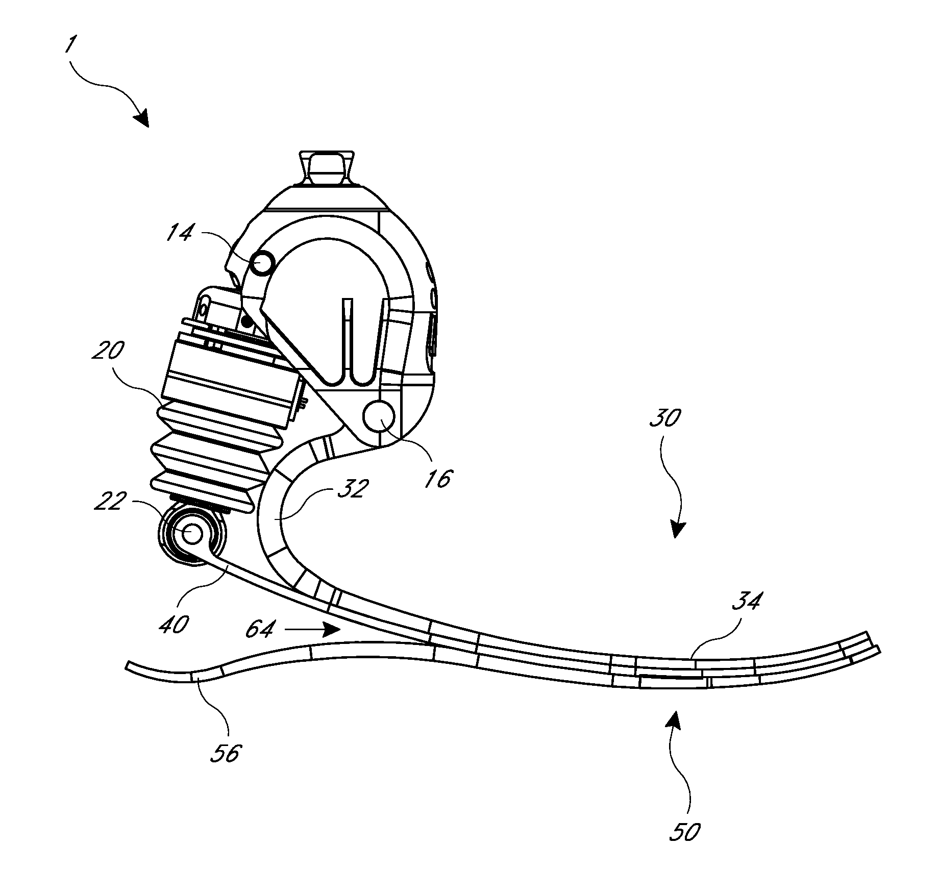
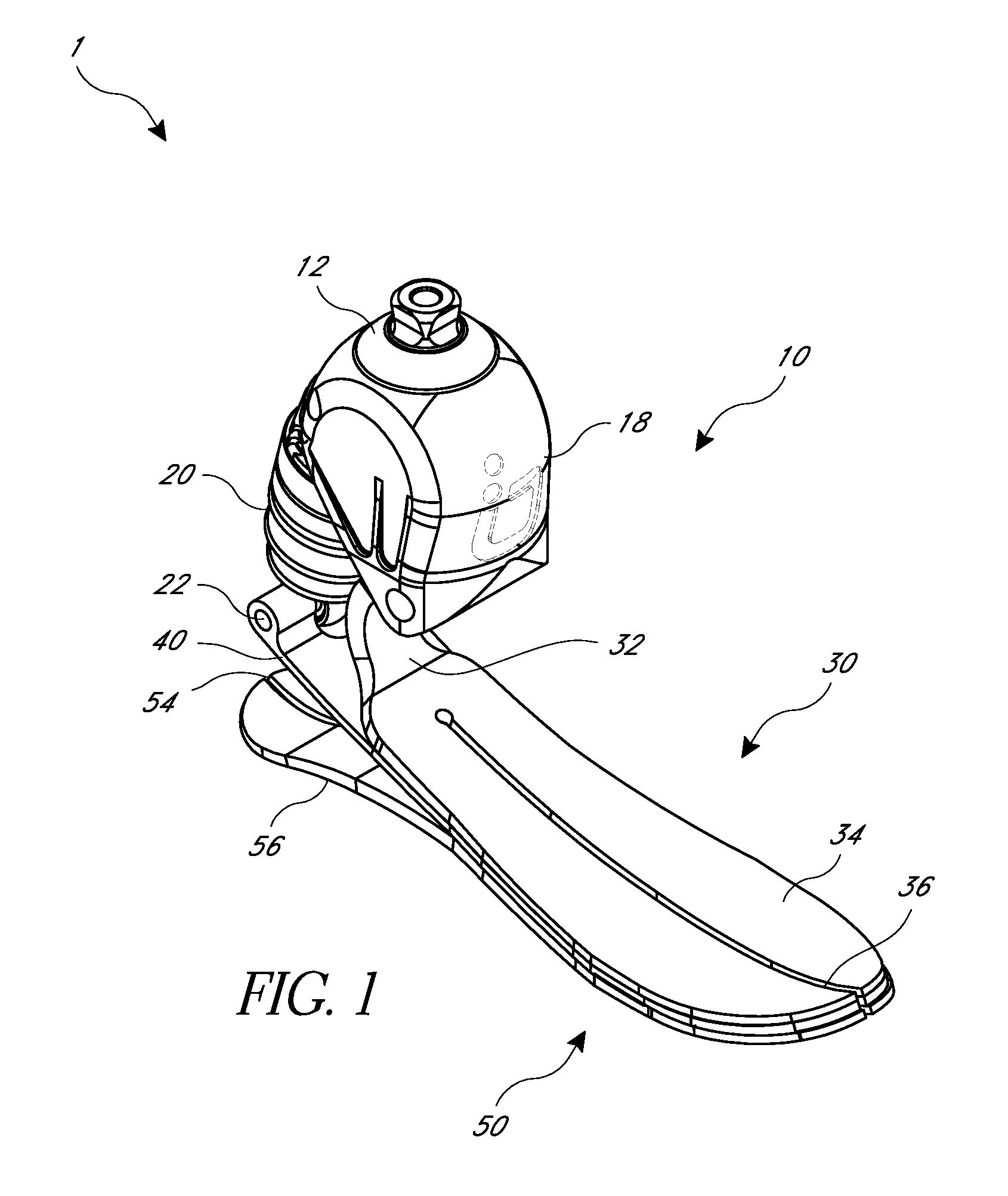
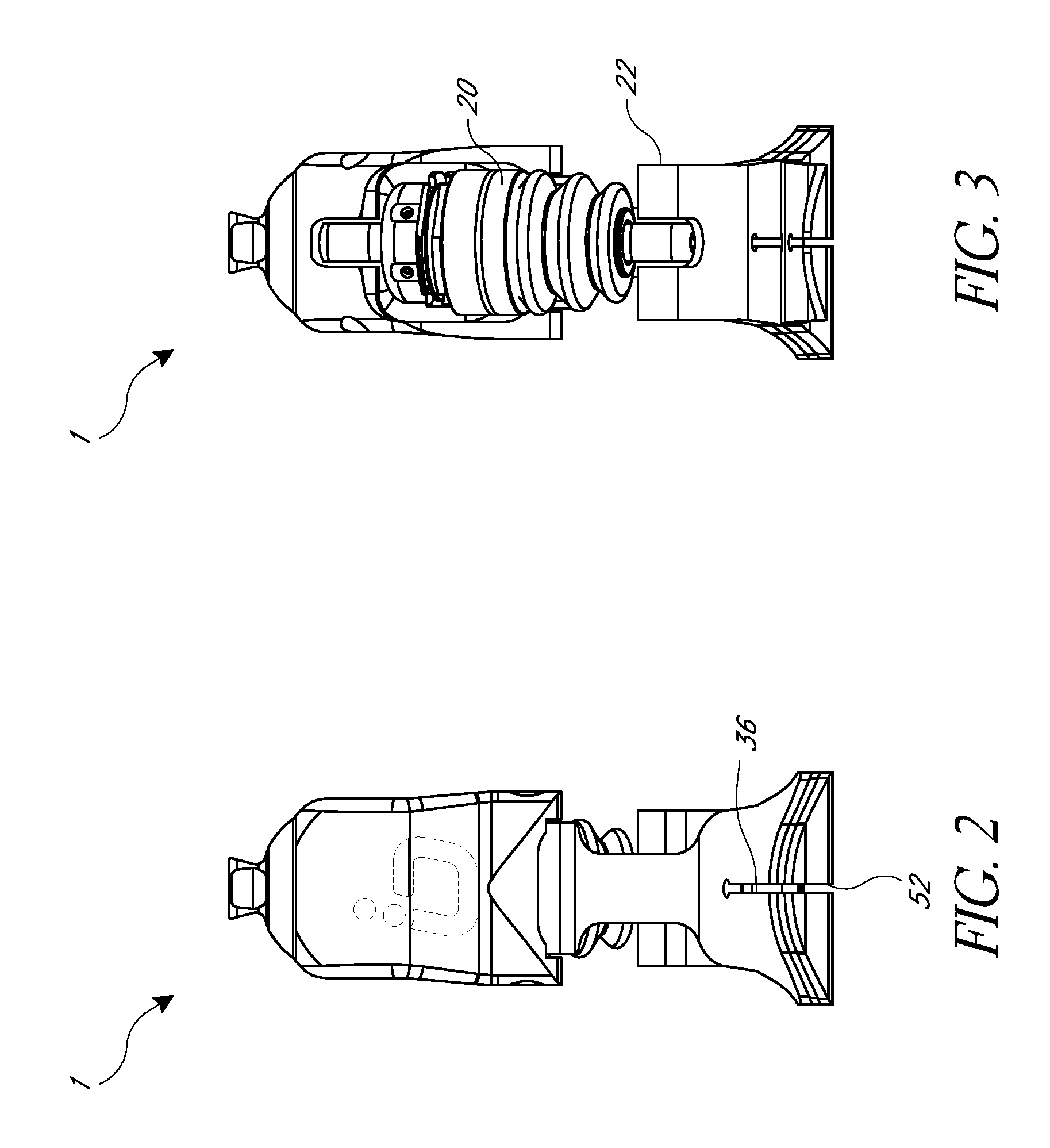
FIG. 1 is a perspective view of an embodiment of a prosthetic foot.
FIG. 2 is a front view of the prosthetic foot of FIG. 1.
FIG. 3 is a rear view of the prosthetic foot of FIG. 1.
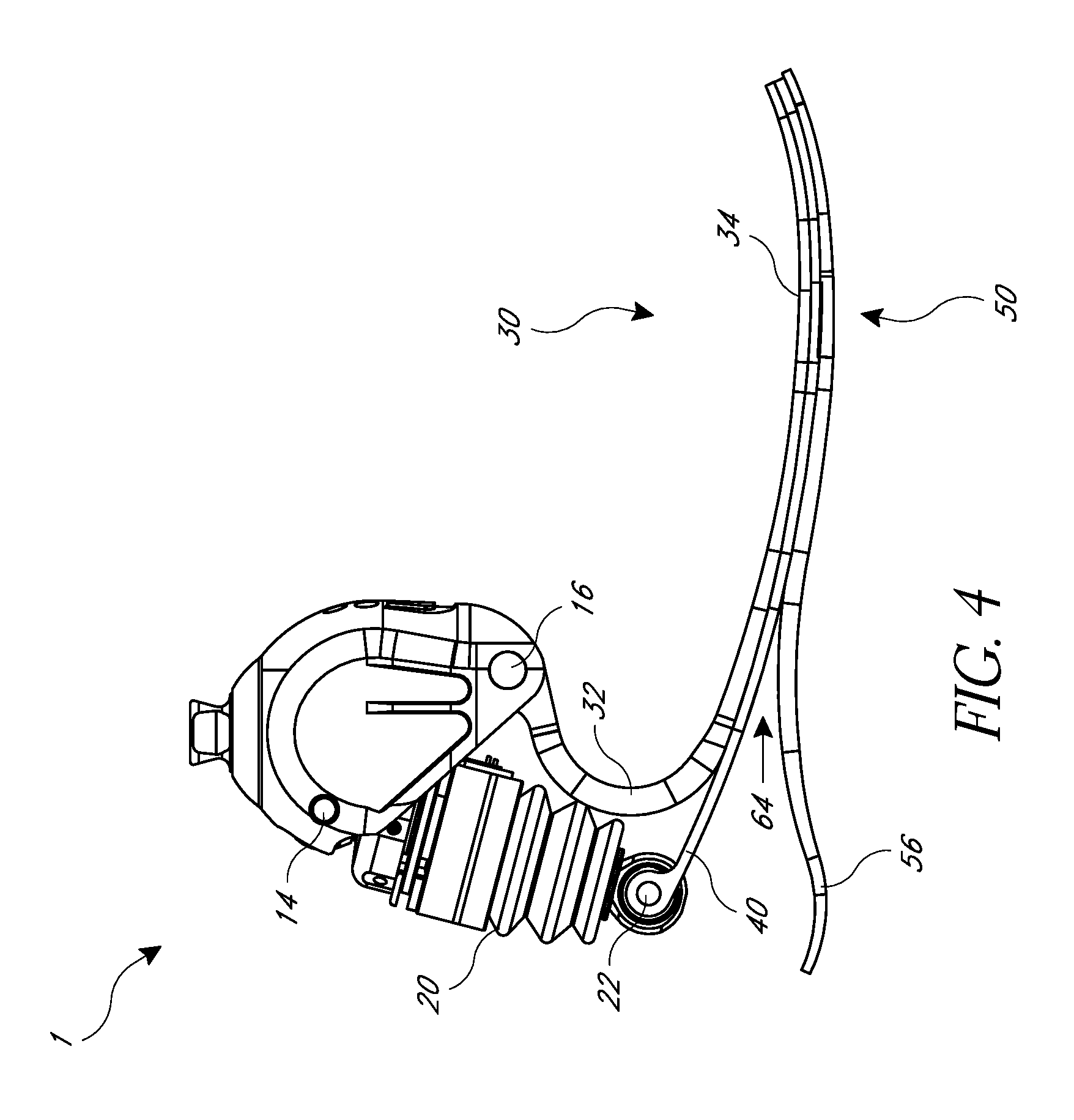
FIG. 4 is a side view of the prosthetic foot of FIG. 1.
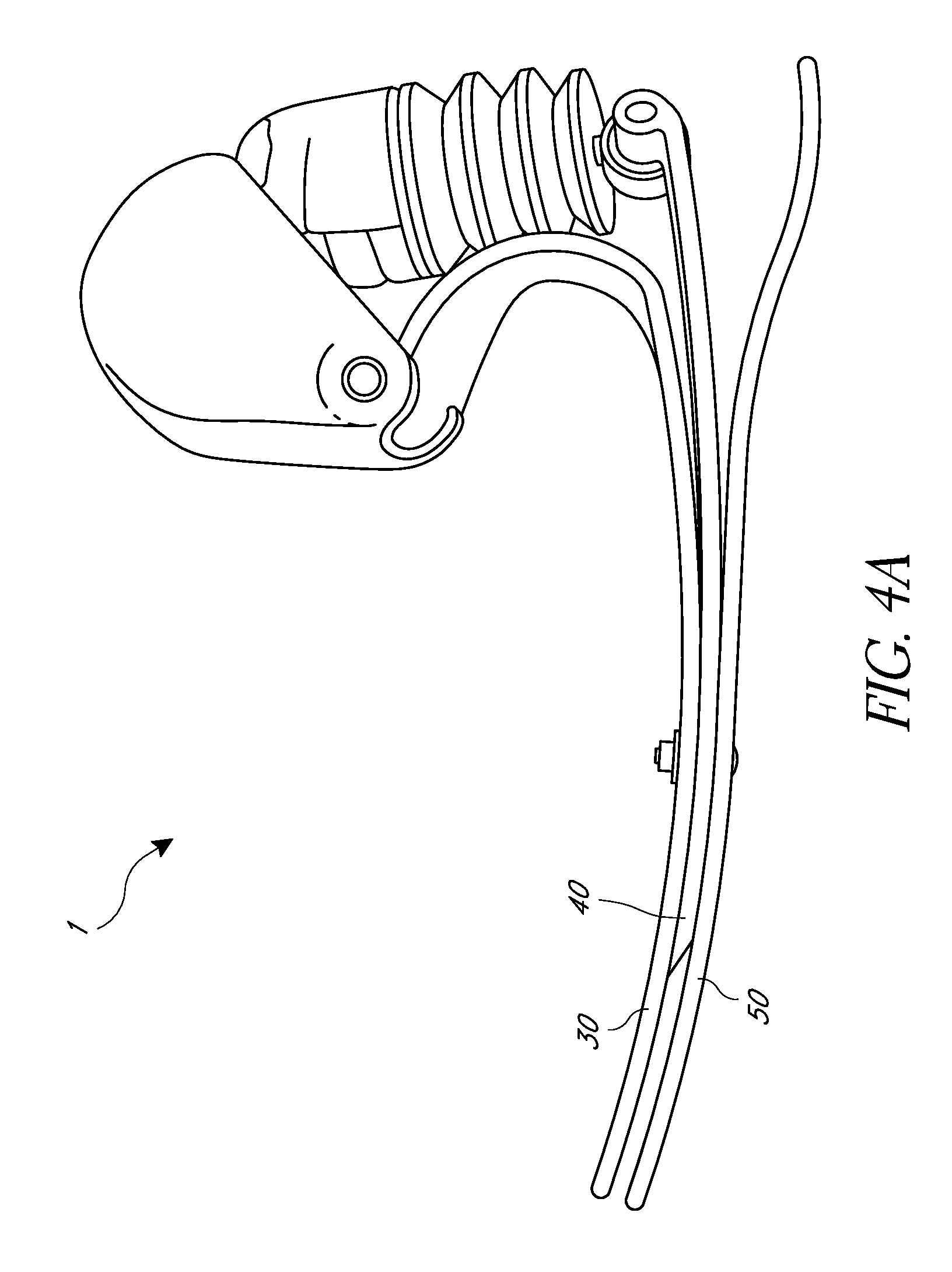
FIG. 4A is a side view of another embodiment of a prosthetic foot, similar to the prosthetic foot of FIG. 1.
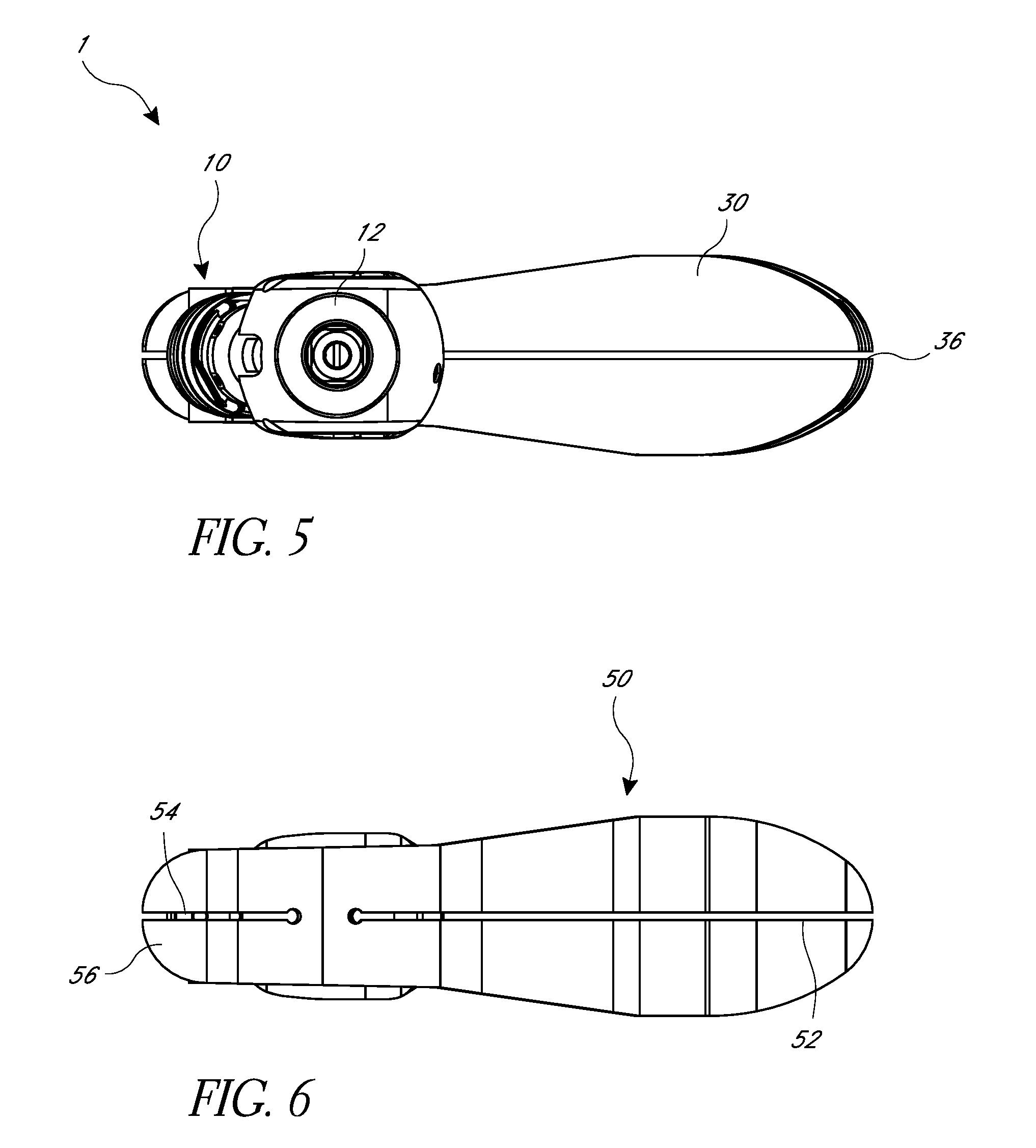
FIG. 5 is a top view of the prosthetic foot of FIG. 1.
FIG. 6 is a bottom view of the prosthetic foot of FIG. 1.
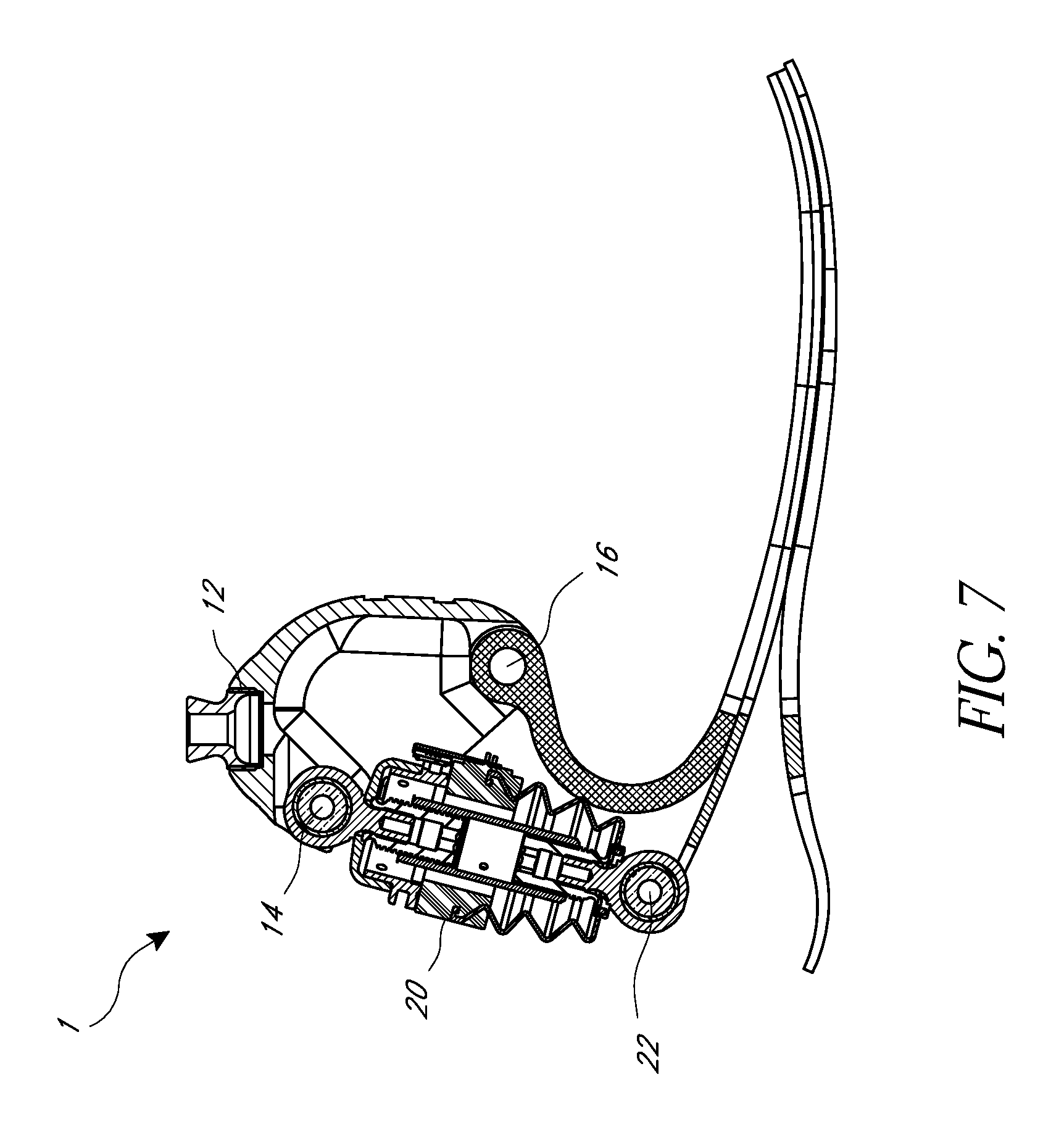
FIG. 7 is a cross-sectional side view of the prosthetic foot of FIG. 1.
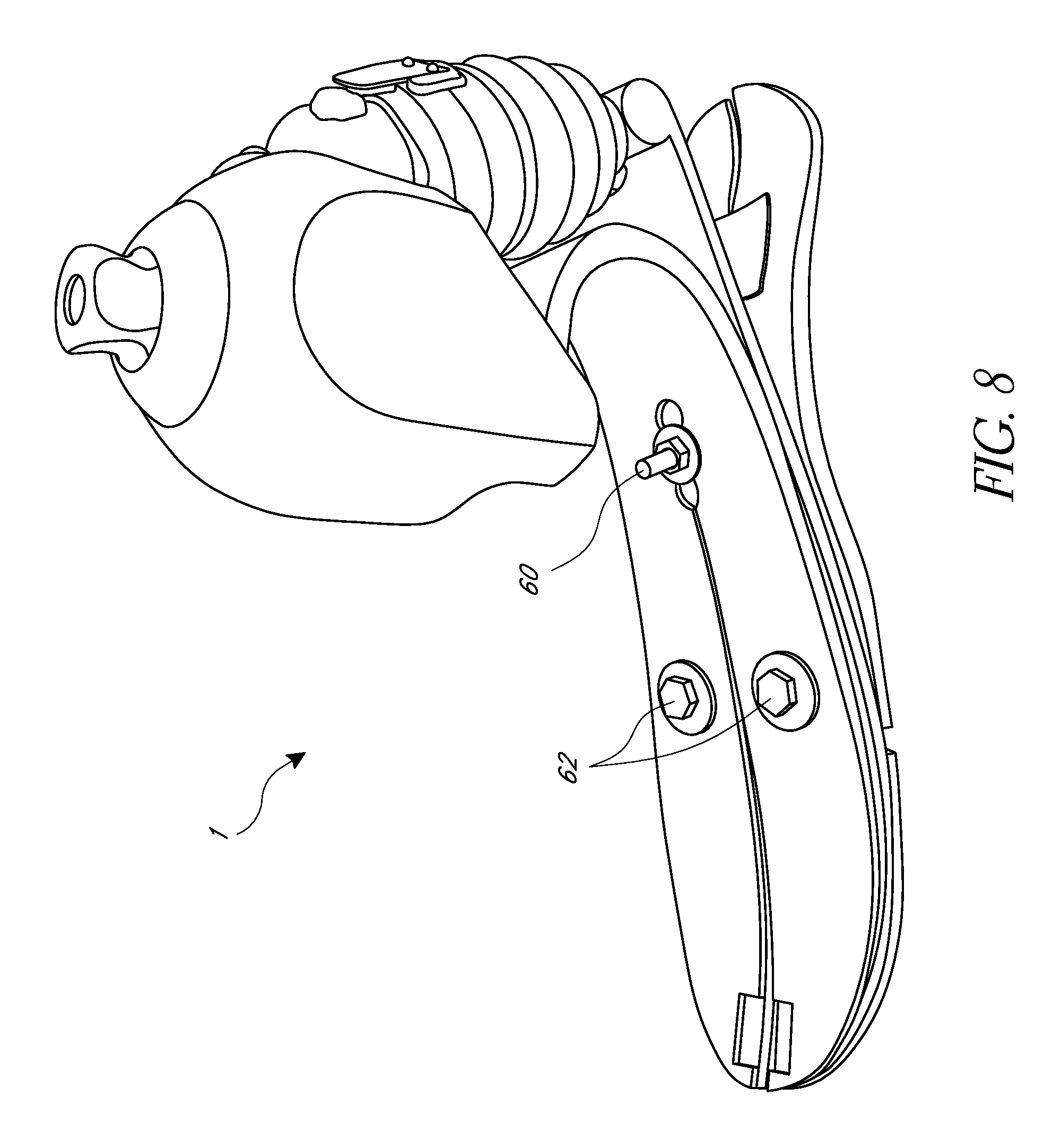
FIG. 8 is a view of the prosthetic foot of FIG. 1 with additional fasteners.
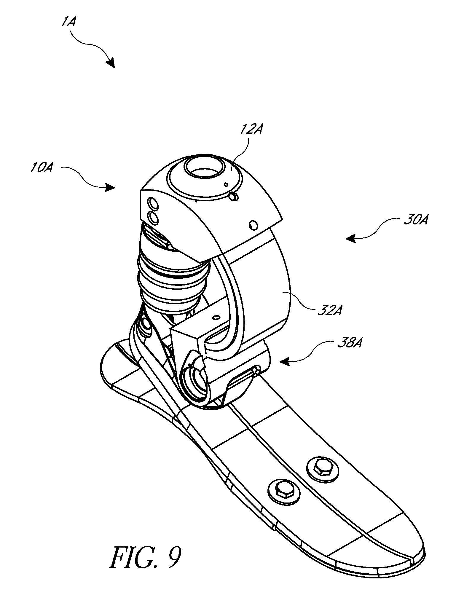
FIG. 9 is a perspective view of another embodiment of a prosthetic foot.
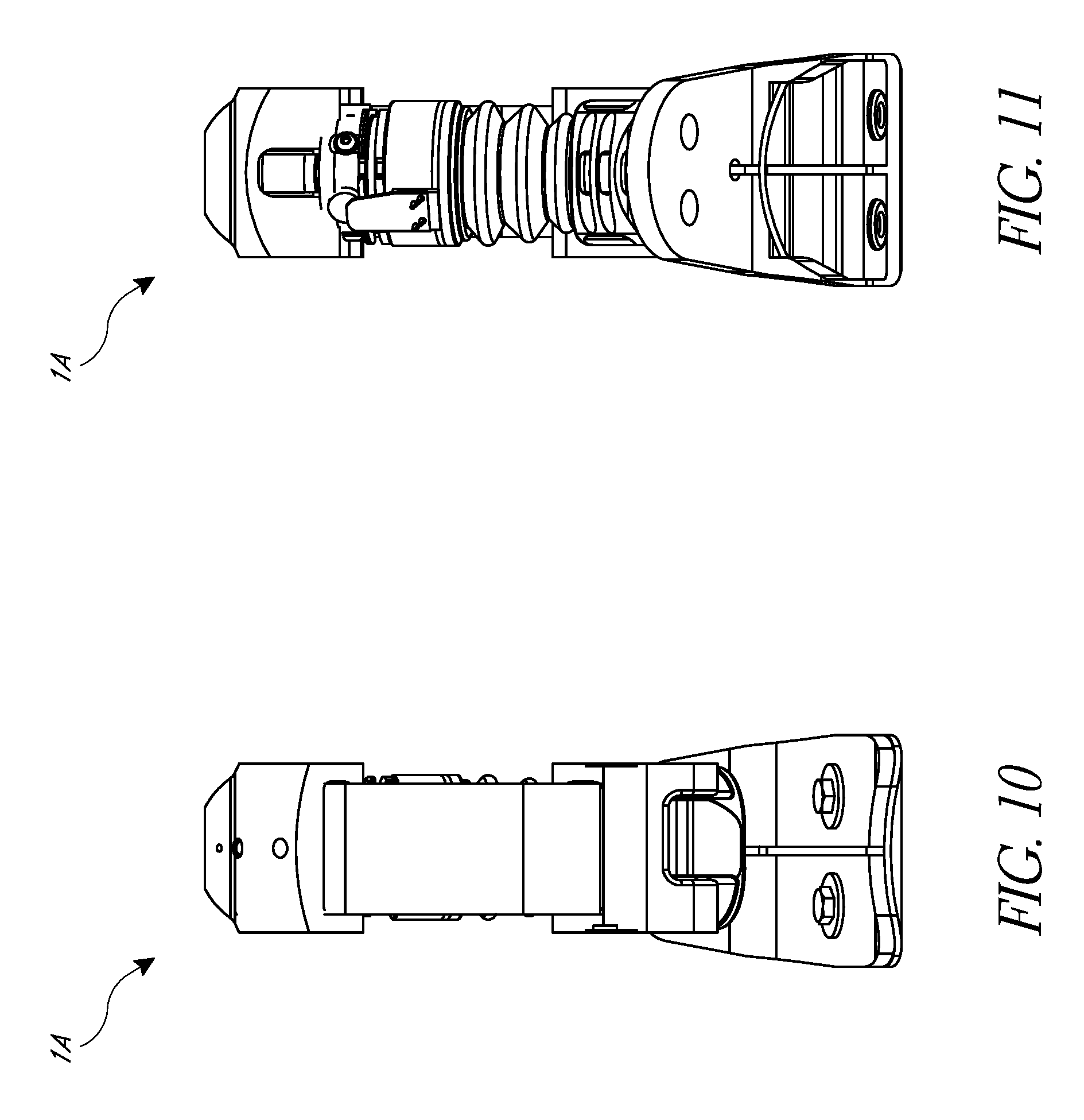
FIG. 10 is a front view of the prosthetic foot of FIG. 9.
FIG. 11 is a rear view of the prosthetic foot of FIG. 9.
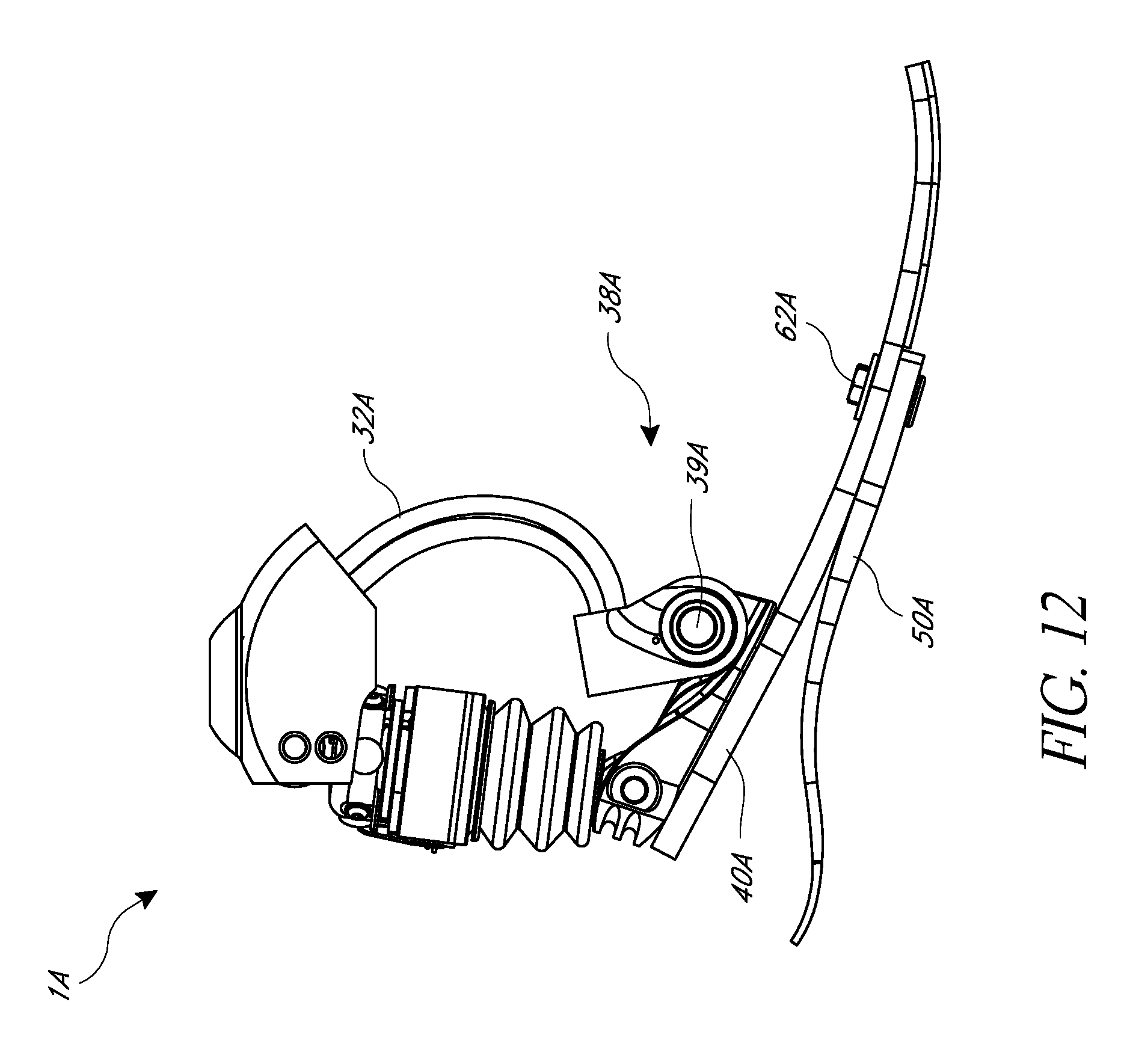
FIG. 12 is a side view of the prosthetic foot of FIG. 9.
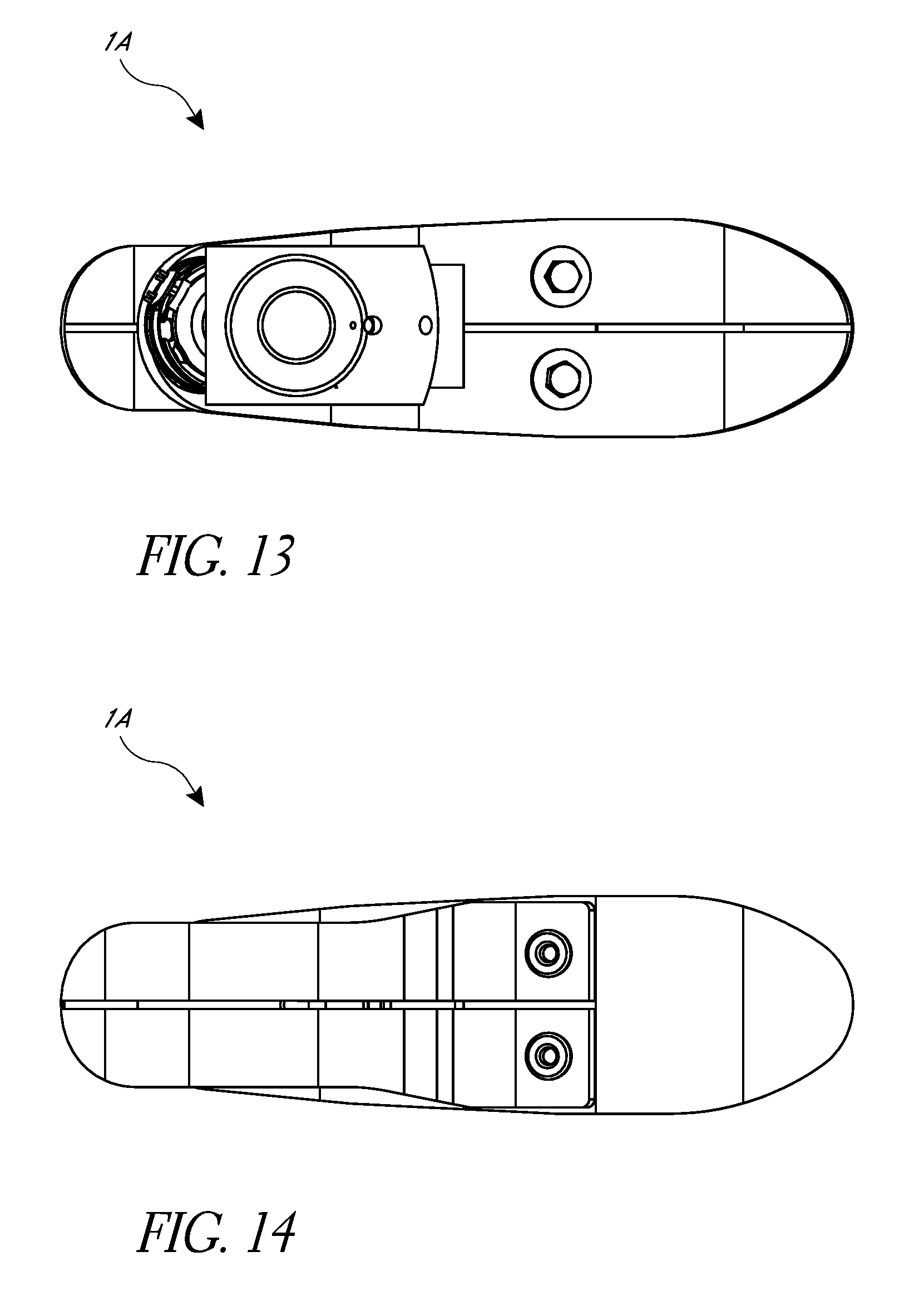
FIG. 13 is a top view of the prosthetic foot of FIG. 9.
FIG. 14 is a bottom view of the prosthetic foot of FIG. 9.
FIG. 15 is a cross-sectional side view of the prosthetic foot of FIG. 9.
FIG. 15A is a cross-sectional view of another embodiment of a prosthetic foot, similar to the prosthetic foot of FIG. 9.
FIG. 16 is a perspective view of another embodiment of a prosthetic foot.
FIG. 17 is a front view of the prosthetic foot of FIG. 16.
FIG. 18 is a rear view of the prosthetic foot of FIG. 16.
FIG. 19 is a side view of the prosthetic foot of FIG. 16.
FIG. 20 is a top view of the prosthetic foot of FIG. 16.
FIG. 21 is a bottom view of the prosthetic foot of FIG. 16.
FIG. 22 is a cross-sectional side view of the prosthetic foot of FIG. 16.
FIG. 23 is a view of the prosthetic foot of FIG. 16 with an additional fastener.
DETAILED DESCRIPTION
FIGS. 1-8 depict an embodiment of a prosthetic foot 1. The prosthetic foot 1 can attach to a user or to another prosthetic device with an attachment member 10. The attachment member 10 is depicted as including a first connection portion 12 shown as a pyramid connector. The pyramid connector can attach to a stump on a user, to another prosthetic device, or to any other appropriate object. Further, it will be understood that the first connection portion 12 can include attachment features other than a pyramid connector, such as a threaded hole or screw, a latch, a magnetic member, tube clamp, or other features.
The attachment member 10 can additionally include second and third connection portions 14, 16 (see FIGS. 4, 7). The attachment member 10 can serve to provide a rigid connection between the connection portions 12, 14, 16. For example, the attachment member 10 can comprise a substantially rigid material such as aluminum, steel, titanium, other metals or metallic alloys, carbon fiber, composites, or substantially rigid plastics. However, in other embodiments the attachment member 10 can be configured to provide flexibility, potentially in multiple planes. Thus, in some embodiments the attachment member 10 can comprise a more flexible material or include flexible joints between separate components of the attachment member 10. For example, in some embodiments the attachment member 10 can have a flexible connection with the first connection portion 12, allowing for motion in the medial/lateral and/or anterior/posterior directions. Further, the connection may allow torsional flexibility with the first connection portion 12. In other embodiments, as further described below, the attachment member 10 can have a flexible connection with one or both of the second and third connection portions 14, 16.
Further, in some embodiments the attachment member 10 can include other features of a prosthetic foot such as sensors configured to measure, for example, the position and movement of the prosthetic foot, the position and movement of various joints and components on the prosthetic foot (such as the rotational position and movement at the connection portions 14, 16 and an actuator 20, as further discussed below), pressures and forces on various components of the prosthetic foot 1 (such as on the attachment member 10, the actuator 20, or the elastic members 30, 40, 50, further discussed below), and other measurable characteristics of the prosthetic foot. The sensors can additionally be configured to measure the prosthetic foot's environment, such as a terrain on which the prosthetic foot 1 moves. It will be understood that these sensors can be positioned on other elements of the prosthetic foot 1, such as the actuator 20, the elastic members 30, 40, 50, and other elements, further described below.
The attachment member 10 can also include electronics (e.g., computer processor). For example, the attachment member 10 can include electronics configured to receive information from the sensors, discussed above. Further, in some embodiments, the attachment member 10 can include electronics configured to communicate information (e.g., information from the sensors) to other electronic devices, such as to other prosthetic devices or to an external computer (e.g., via wired or wireless communication, such as RF communication). Such electronics may also be configured to receive information from other prosthetic devices or an external computer, such information potentially including information from other sensors and/or operational commands for the prosthetic foot 1.
The attachment member 10 can additionally include or define a cover 18. The cover 18 can protect various components of the prosthetic foot 1 such as electronics (as described above), the actuator 20 (describe below), or other components. In some embodiments the cover 18 can include open portions in the coronal plane, allowing flexibility of motion in the medial-lateral directions. In further embodiments the cover 18 can include open portions in the sagittal plane, allowing flexibility of motion in the anterior-posterior directions. In some embodiments, the open portions can be vertical or horizontal slots formed in the cover 18, to allow movement of pivot axles associated with any one of the connection portions 12, 14, 16.
As shown in FIG. 1, the attachment member 10 can connect to a first elastic member 30 at the third connection portion 16. In some embodiments the third connection portion 16 can provide a rotatable connection, although non-rotatable connections can also be used. In some embodiments, the rotation can be provided by an axle firmly mounted to the attachment member 10, about which the first elastic member 30 can rotate. In other embodiments, the first elastic member 30 can be fixed to the axle, and relative rotation can be allowed between the axle and the attachment member 30. In one embodiment, the first elastic member 30 can include or define a bushing or opening through which the axle extends. The first elastic member 30 can be formed from a sufficiently flexible material such as carbon fiber, though other suitable materials or combination of materials can be used (e.g., carbon and glass fibers). In other embodiments, the first elastic member 30 can be substantially inelastic, so as to provide a rigid connection. It will be understood that the other elastic members 40, 50 (described further below) can be formed of similar materials and have similar connections as the first elastic member 30.
Further, the first elastic member 30 can be formed into a shape configured to provide a desired flexibility or rigidity. As shown in FIG. 1, the elastic member 30 includes a C-shaped portion 32 at an upper portion (proximal portion) of the first elastic member, near the third connection portion 16. The C-shaped portion 32 is depicted as including an opening facing forward (e.g., the C-shaped portion 32 curves forwardly so that it is concave toward the front of the prosthetic foot), although in other embodiments the C-shaped portion can have an opening facing backward (e.g., the C-shaped portion can curve rearwardly so that it is concave toward the rear of the prosthetic foot). In some embodiments, the C-shaped portion 32 can bend more than 90 degrees, more than 110 degrees, 130 degrees, 150 degrees, or 170 degrees when unloaded. The bend of the C-shaped portion 32 can affect the resistance or flexibility of the first elastic member 30. Notably, this resistance or flexibility can be adjusted, as described further below.
In the embodiment of FIG. 1, the elastic member 30 can extend from the lower portion of the C-shaped portion 32 into a foot portion 34. The foot portion 34 of the elastic member 30 can be substantially flat and extend from a rear portion of the prosthetic foot 1 toward a toe region of the prosthetic foot 1. The foot portion 34 can further include a slit 36. As shown, the slit 36 extends longitudinally to a toe end of the elastic member 30 to separate the foot portion 34 into two or more foot members that can flex independently, although in some embodiments the slit 36 can be closed at the toe end (e.g., where at least one of the elastic members 30, 40, 50 are solid at a toe portion such that the slit terminates prior to the end of the at least one elastic member). As will be discussed further below, the slit 34 can allow the flexibility and resistance of the elastic member 30 to be altered. In another embodiment, the elastic members 30, 40, 50 can be monolithic without any slits.
As further shown in FIG. 4, the attachment member 10 can connect to an actuator 20 at the second connection portion 14. Like the third connection portion 16, the second connection portion 14 can be rotatable or non-rotatable. Notably, in FIG. 4 the third connection portion 16 is in a front portion of the attachment member 10, and the second connection portion 14 is in a rear portion of the attachment member 10. Similarly, the actuator 20 is located at a rear portion of the prosthetic foot 1. However, in other embodiments the actuator 20 can be positioned in a front portion of the prosthetic foot 1, as further described below.
The actuator 20 can be in a variety of forms and can be operated in a variety of ways, as described by way of example in U.S. patent application Ser. No. 11/367,049, issued Mar. 1, 2011 as U.S. Pat. No. 7,896,927, and U.S. patent application Ser. No. 12/816,968, published as U.S. 2010/0324698 on Dec. 23, 2010, both of which are incorporated herein by reference and should be considered a part of this specification. For example, the actuator 20 can be a powered actuator such as a screw motor, or a passive member such as an elastic member (e.g., a spring) or a chamber with a magnetorheologic fluid, or can be a hydraulic or pneumatic system. Further, the actuator 20 can be configured to operate in a variety of ways, as also discussed in U.S. Pat. No. 7,896,927 and U.S. 2010/0324698. For example, the actuator 20 can be configured to extend or contract to assist a user during a gait cycle. For example, the actuator 20 can change the orientation of the prosthetic foot 1 to dorsiflexion and then to plantarflexion during a swing phase of gait cycle so that the toe portion of the prosthetic foot 1 is raised during the initial portion of swing phase. In another embodiment, the actuator 20 can change the orientation of the prosthetic foot 1 to plantarflexion when the user is in a relaxed (e.g., sitting) position. Further, such motion of the actuator 20 can change the flexibility or resistance of the elastic members 30, 40, 50, as further described below. In some embodiments, the actuator 20 can also enter a low power mode (e.g., hibernation mode), such as a relaxed mode or an inactive mode. For example, the actuator 20 may enter a low power mode during stance, as the embodiments described herein can provide greater stability during stance, as further described below. Advantageously, the low power mode allows for the conservation of battery power used to power the actuator 20, allowing the actuator 20 to be operated for longer periods of time between battery charging.
The actuator 20 is depicted as connecting to a second elastic member 40 at a fourth connection portion 22. Like the second and third connection portions 14, 16, the fourth connection portion 22 can be rotatable or non-rotatable. In one embodiment, the second elastic member 40 can include or define a bushing or opening through which an axle extends to provide a rotatable connection or pivot axis between the second elastic member 40 and the actuator 20. The second elastic member 40 can extend into a foot portion in a manner similar to the foot portion 34 of the first elastic member 30. In one embodiment, the second elastic member 40 can extend to a distal end of the prosthetic foot 1, so that the first and second elastic members 30, 40 extend to generally the same location at the distal end of the prosthetic foot 1. Further, the second elastic member 40 can include a slit similar to the slit 36 of the first elastic member 30. Even further, the second elastic member 40 can be composed of materials similar to those for the first elastic member, such as carbon fiber. As shown, the second elastic member 40 is disposed below the first elastic member 30, and extends tangentially forward and toward the first elastic member to abut the first elastic member 30 along the foot portion 34 of the first elastic member 30. Although the first and second elastic members 30, 40 are depicted as ending at approximately the same point at a toe portion of the prosthetic foot, in some embodiments the first elastic member 30 may extend further, or the second elastic member 40 may extend further. For example, as depicted in FIG. 4A, the first and third elastic members 30, 50 can extend further than the second elastic member 40, creating a gap between the first and third elastic members 30, 50. In other embodiments, a gap can be provided between the first and second elastic members 30, 40 in a toe region of the prosthetic foot, as shown in FIG. 8. As a further example, as depicted in, for example, FIG. 12 the third elastic member 50 (e.g., member 50A, described below) can end before a toe portion of the prosthetic foot 1, such as at a metatarsal region of the foot. The first and/or second elastic members 30, 40 (e.g., only second elastic member 40A in FIG. 12) can then extend past the third elastic member 50 to the toe portion.
The prosthetic foot 1 can further include a third elastic member 50. As shown, the third elastic member 50 can extend from a heel portion 56 (e.g., a cantilevered or free end) at a bottom and rear portion of the prosthetic foot 1. This heel portion 56, as shown, can be spaced from the actuator 20 and the second elastic member 40, curving downward toward and away from the actuator 20. From the heel portion 56, the third elastic member 50 can extend to a toe portion of the prosthetic foot 1, and can generally abut the foot portion second elastic member 40, as that member abuts the first elastic member 30. Further, the third elastic member 50 can have a slit along this foot portion that generally matches the slits in the first and second elastic members 30, 40. Additionally, as shown, the third elastic member 50 can include a heel slit 54 in the heel portion 56 of the elastic member.
As shown in the figures, the slit 36 in the first elastic member 30 can align with the slit in the second elastic member 40 and the slit 52 in the third elastic member 50 in the foot portion 34. In one embodiment, the prosthetic foot 1 can have a stiffness control member 60 that can be actuated to vary the stiffness of the prosthetic foot. In some embodiments, the stiffness control member 60 can be a fastening member 60 (e.g., bolt and nut, clamp, staple, rivet, etc.) that couples two or more of the elastic members 30, 40, 50 to each other, where the fastening member 60 can travel along the slit 36 or a slot defined at least partially by the slit, best shown in FIG. 8, or travel along a slot in the elastic members 30, 40, 50 where the elastic members do not have a slit. Attachment can be provided between the elastic elements 30, 40, 50, for example, generally in a metatarsal region of the prosthetic foot 1. Advantageously, in some embodiments the fastening member's 60 position can be adjustable along the length of the slit 36. For example, when the fastening member 60 is a bolt and nut, the bolt can be moved to any desired position along the slit 36 and then fastened into place by tightening the nut. In some embodiments, an undercut or recess in the elastic members 30, 40, 50 can be provided to prevent the bolt and nut from protruding outwards. Notably, the position of the fastening member along the slit 36 can alter the flexibility and resistance of the elastic members 30, 40, 50. Where the elastic members 30, 40, 50 are not held together (e.g., by the fastening member) they can separate and act as distinct elastic members instead of combining into a single elastic member where held together. Thus, if the fastening member 60 is moved forward, the elastic members 30, 40, 50 are held together over a shorter range, allowing more separation between them, and thus greater flexibility (e.g., the lever arm of the second elastic member 40 is relatively longer, resulting in greater flexibility of the prosthetic foot 1). Alternatively, if the fastening member is moved rearward, the elastic members 30, 40, 50 are held together over a longer range, reducing the allowed separation and flexibility (e.g., the lever arm of the second elastic member 40 is relatively shorter, resulting in increased stiffness of the prosthetic foot 1). Advantageously, the fastening member 60 can be adjusted to vary the stiffness of the prosthetic foot 1.
In some embodiments, the stiffness control member 60 can be mechanically actuated, either manually by the user or automatically (e.g., actively adjusted) during ambulation by the user (e.g., based on the activity level of the user or the phase of gait cycle).
Notably, as discussed above, in some embodiments, the flexibility and resistance of the elastic members 30, 40, 50 can also be altered by the actuator 20 (independently of, or in combination with, the stiffness control member 60). Thus, it will be understood that the flexibility and resistance of the elastic members 30, 40, 50 can be altered manually and/or by an actuator. In further examples, the stiffness control member 60 can be moved (e.g., automatically moved) by an actuator to adjust the resistance and flexibility of the elastic members 30, 40, 50.
In some embodiments, it may be preferable to adjust the flexibility and resistance of the elastic members 30, 40, 50 to reduce resistance and increase flexibility while moving on level ground. Thus, for example, the stiffness control member 60 can be moved forward while ambulating on level ground to provide faster plantarflexion after heel strike. During other gait patterns, such as walking downstairs, one can reduce flexibility and increase resistance by moving the stiffness control member 60 backward. In some embodiments, these gait patterns can be detected by sensors and processors provided on or in communication with the prosthetic foot 1. An actuator can then be controlled to adjust the flexibility and resistance of the elastic members 30, 40, 50 according to the detected gait pattern.
Variations to the embodiment in FIGS. 1-8 are possible. For example, in the depicted embodiment a stiffness control member 60 (e.g., fastening member 60) can be moved to various positions along the slit 36, such that the resistance and flexibility of the elastic members 30, 40, 50 can be varied. However, in other embodiments it may be preferable to remove the slit 36 such that the elastic members 30, 40, 50 are more solid and provide a more uniform resistance. Further, in some embodiments it may be preferable to bond the elastic elements 30, 40, 50 in another manner, such as with an adhesive, so they remain permanently attached. The elastic elements 30, 40, 50 can also be held together with additional fastening members 62, depicted as nuts and bolts in FIG. 8, in addition to the adjustable fastening member 60. In other embodiments, one or more of the elastic elements 30, 40, 50 can be formed together into a single piece. For example, in some embodiments the second and third elastic members 40, 50 can be formed as a single piece.
In further embodiments this resistance can be varied by other methods. For example, in some embodiments the stiffness control member can be a wedge or insert that can be inserted where two or more of the elastic members 30, 40, 50 meet. For example, a wedge can be inserted between the first and second elastic members 30, 40 (e.g., above the second and below the first). Similarly, a wedge can be inserted between the second and third elastic members 40, 50, such as at a wedging location 64, depicted in FIG. 4. The wedge can limit the range of motion of the elastic members 30, 40, 50 relative to each other, thus increasing their resistance. The size and shape of the wedge can be chosen to cause a particular desired resistance. Further, the wedge can be moved forward or rearward to vary the flexibility and resistance between the elastic members 30, 40, 50.
The depicted embodiment also combines three separate elastic elements 30, 40, 50 that each provide a separate function. For example, the first elastic element 30 acts as a spring in parallel with the actuator 20. Further, the second elastic element 40 acts as a spring in series with the actuator 20. Both elastic elements 30, 40 can thus be configured to work with or against the actuator 20 at different phases of the gait cycle. Further, the elastic elements 30, 40 can be loaded or unloaded by the actuator 20. Providing one spring in parallel and the other in series allows each spring to have a different effect on the dynamics of the prosthetic foot 1 during movement. For example, during heel strike, the actuator 20 and second elastic member 40 can act in series to provide the prosthetic foot 1 with a certain level of flexibility in addition to the energy stored by the third elastic member (e.g., be relatively less stiff at heel-strike), while during toe-off, the actuator 20 and first elastic element 30 can act in parallel to provide the prosthetic foot with a different level of flexibility (e.g., be relatively more stiff at toe-off). Thus, the independent flexibility and resistance of the elastic elements 30, 40 can be chosen separately to optimize the behavior of the prosthetic foot 1.
Notably, in the depicted embodiment the first and second elastic members 30, 40 both extend toward the toe along the foot portion 34. However, they do not extend toward the heel of the prosthetic foot 1. The third elastic member 50 includes a heel portion 56. The heel portion 56 thus provides flexibility and resistance to the prosthetic foot 1 during heel strike. This response during heel strike can be determined independently of a flexibility and resistance during toe-strike or toe-off during a gait cycle, as the third elastic element 50 is a separate piece from the first and second elastic elements 30, 40. Thus, for example, a system of separate elastic members 30, 40, 50 can include versions of each elastic member with varying flexibilities and resistances. One can then choose each elastic member 30, 40, 50 to provide a desired flexibility and resistance at different times during a gait cycle, depending on the needs of a particular user.
In further embodiments, the actuator 20 can be removed or replaced with a rigid member. For example, in some embodiments the second elastic member 40 can connect directly to the second connection portion 14. In such embodiments, the first and second elastic members 30, 40 can both be rotatably connected to the attachment member 10. Further, in embodiments where the second elastic member 40 does not connect directly to the second connection portion 14, it can still rotatably connect to an intermediary member (such as a rigid member replacing the actuator 20) at a fourth connection portion 22 (as described above). In such embodiments, the three rotatable connections 14, 16, 22 can form a triangle with at least one elastic portion, the elastic portion being both the first and second elastic members 30, 40, between the fourth connection portion 22 and the third connection portion 16.
The rotatable connections 14, 16, 22 with the elastic members 30, 40 can provide a flexible resistance to rotation of the attachment member 10. Advantageously, the use of both first and second elastic members 30, 40 can provide for a natural rocking motion during stance that can provide improved stability with the prosthetic foot 1. This stability can also be provided in embodiments that include an actuator 20, e.g., when the actuator 20 is locked in a particular position or is substantially inactive.
FIGS. 9-15 depict a second embodiment of a prosthetic foot 1A. It will be understood that the prosthetic foot 1A in these figures has features similar to the prosthetic foot 1 described above, and thus will be described in terms of its differences. As shown, the prosthetic foot 1A includes a first elastic member 30A having a C-shaped portion 32A, similar to that in the previously described embodiments. However, in the present embodiment the C-shape portion 32A can be reversed to have an opening facing rearward (e.g., the C-shaped portion 32A has a concave shape facing toward the rear of the prosthetic foot 1). Further, as shown, the first elastic member 30A can include two parallel elastic pieces. Additionally, as shown, the first elastic member 30A can attach to the attachment member 10A at a second connection portion 14A that is non-rotatable, although in other embodiments the second connection portion 14A can be rotatable (e.g., via a pivot location, as shown in previous embodiments). Further, as shown, the first elastic member 30A can be shortened to not include a foot portion, like the foot portion 34 in the previous embodiments. Instead, the first elastic member 30A can attach to a fifth connection body 38A, also via a non-rotatable connection. However, the fifth connection body 38A can provide a rotatable connection to the second elastic member 40A, as shown in the figures, via a supplemental connection body 39A that can be considered to be part of the fifth connection body 38A.
Notably, the features in the embodiment in FIGS. 9-15 also form a triangle with at least one elastic portion and three rotatable connections, similar to that discussed above in the previous embodiment. For example, as best shown in FIG. 15, the prosthetic foot 1A includes a second connection portion 14A between the attachment member 10A and the actuator 20A. The actuator 20A can include a fourth connection portion 22A, connecting to the second elastic member 40A. The second elastic member 40A can connect to the first elastic member 30A with fifth connection body 59A. The first elastic member 30A can attach to the attachment member 10A, completing the triangle. In some embodiments, only one portion of the triangle can have an elastic portion. For example, in some embodiments the second elastic member 40A can be an inelastic or rigid member.
Further, in some embodiments the C-shaped portion 32A can be substantially similar to that shown in FIGS. 9-15, but include an additional elastic member 66A generally aligned with the C-shaped portion 32A, as best shown in FIG. 15A. The additional elastic member 66A can connect to the attachment member 10A in a manner similar to the first elastic member 30A. The additional elastic member 66A can then extend tangent with the first elastic member 30A along the C-shaped portion 32A and terminate at a free end unattached to the fifth connection body 39A. A stiffness control member similar to the stiffness control member 60 can then be provided between the C-shaped portion 32A and the additional elastic member 66A. For example, slits can be provided in the C-shaped portion 32A and the additional elastic member 66A to receive a fastening member that can be moved along the length of the slit to adjust the flexibility and resistance of the C-shaped portion 32A, as illustrated. In further embodiments, such adjustability of the flexibility and resistance of the elastic members 30A, 40A, 50A can be provided with other suitable mechanisms. For example, in some embodiments the fifth connection body 38A (including the supplemental connection body 39A) can be movable in an anterior-posterior direction along the second elastic member 40A to change the location of the fifth connection body 38A on the second elastic member 40A. For example, in some embodiments the second elastic member 40A can include a slot that can receive a fastener to fasten the fifth connection body 38A in place along the second elastic member. However, other suitable mechanisms can be used to adjust the location of the fifth connection body 38A relative to the second elastic member 40A (e.g., a track and worm gear arrangement).
Additionally, the depicted prosthetic foot 1A depicts an alternative method for attaching the second and third elastic members 40A, 50A. As shown, these members can be attached by two bolts 62A, on opposite sides of the slit 36A. However, it will be understood that other attachment methods can be used, such as those described above. Further, an adjustable fastening member can be provided in the slit 36A, as discussed above, to vary the flexibility and resistance of the prosthetic foot 1A.
FIGS. 16-23 depict yet another embodiment of a prosthetic foot 1B. It will again be understood that the prosthetic foot 1B in these figures has features similar to the prosthetic foot 1 described above, and thus will be described in terms of its differences. As shown, the prosthetic foot 1B provides a design with the actuator 20B in a forward portion of the prosthetic foot. As shown, the attachment member 10B can still attach to the first elastic element 30B at a rotatable third connection portion 16B. However, the third connection portion 16B can be provided at an upper rear portion of the attachment member 10B. The second connection portion 14B can connect to the actuator 20B at a lower forward portion of the attachment portion 10B. The actuator 20B can then extend upwards from the second connection portion 14B to attach to the second elastic member 40B. The second elastic member 40B can then form a C-shaped portion that follows the forward-facing C-shaped portion 32B in the first elastic member 30B.
Connection of the third elastic member 50B is depicted as being substantially similar to the third elastic member 50A depicted in FIGS. 9-15. Similar variations can also be provided, as discussed above. Further, as shown, the first elastic member 30B can extend to a foot portion 34A and attach to the second and third elastic members 40B, 50B by the same bolts 62B. Further, as shown, the second elastic member 40B can extend beyond the first and second elastic members 30B, 50B, to a toe portion of the prosthetic foot 1B.
Notably, the features in the embodiment in FIGS. 16-23 also form a triangle with at least one elastic portion and three rotatable connections, similar to that discussed above in the previous embodiments. For example, as best shown in FIG. 22, the prosthetic foot 1B includes a second connection portion 14B between the attachment member 10B and the actuator 20B. The actuator 20B can include a fourth connection portion 22B, connecting to the second elastic member 40B. The second elastic member 40A can come to abut the first elastic member 30B, as described above regarding the previous embodiments. The first elastic member 30B can attach to the attachment member 10B at the third connection portion 16B, completing the triangle.
Further, as best shown in FIG. 23, the first and second elastic members 30B, 40B can be connected by a stiffness control member 60B. In the illustrated embodiment, the stiffness control member 60B is an adjustable fastening member 60B and can allow for varied resistance and flexibility in a manner similar to that in the embodiments discussed above. In the present embodiment, the adjustable fastening member 60B is provided between only the first and second elastic members 30B, 40B (and not the third elastic member 50B), and in a rear portion of the prosthetic foot 1B. Moving the adjustable fastening member 60B downward and forward results in a lever arm of the first and second elastic members 30B, 40B between the fastening member 60B and the attachment member 10B that is relatively longer, resulting in increased flexibility of the prosthetic foot 1B. Alternatively, moving the adjustable fastening member 60B upward results in a lever arm of the first and second elastic members 30B, 40B between the fastening member 60B and the attachment member 10B that is relatively shorter, resulting in increased stiffness of the prosthetic foot 1B.
Advantageously, the prosthetic foot 1, 1A, 1B embodiments disclosed can provide for a natural rocking motion during a stance phase of gait that can provide improved stability to the prosthetic foot 1, 1A, 1B (e.g., the attachment member 10, 10A, 10B can move relative to one or more of the elastic members during stance). This improved stability can also be provided in embodiments that include an actuator 20, 20A, 20B, e.g., when the actuator 20, 20A, 20B is locked in a particular position or is substantially inactive. Additionally, in some embodiments, the prosthetic foot can include a stiffness control member that can be mechanically actuated (e.g., manually or automatically) to vary a stiffness of one or more elastic members of the prosthetic foot to provided different levels of stiffness (e.g., during different types of gait).
Conditional language used herein, such as, among others, "can," "could," "might," "may," "e.g.," and from the like, unless specifically stated otherwise, or otherwise understood within the context as used, is generally intended to convey that certain embodiments include, while other embodiments do not include, certain features, elements and/or states. Thus, such conditional language is not generally intended to imply that features, elements and/or states are in any way required for one or more embodiments or that one or more embodiments necessarily include logic for deciding, with or without author input or prompting, whether these features, elements and/or states are included or are to be performed in any particular embodiment.
While the above detailed description has shown, described, and pointed out novel features as applied to various embodiments, it may be understood that various omissions, substitutions, and changes in the form and details of the ground contact sensing system, including the sensor components, logical blocks, modules, and processes illustrated may be made without departing from the spirit of the disclosure. As may be recognized, certain embodiments of the systems described herein may be embodied within a form that does not provide all of the features and benefits set forth herein, as some features may be used or practiced separately from others. Additionally, features described in connection with one embodiment can be incorporated into another of the disclosed embodiments, even if not expressly discussed herein, and the prosthetic device having the combination of features still fall within the scope of the invention.
* * * * *
References
-
youtube.com/watch?v=lqjtTzNEd54&feature=youtu.be%3E
-
springipedia.com/extension-design-theory.aspasarchivedDec
-
xsens.com/images/stories/PDF/Activity_Recognition_Final_ION_2010_Paper.pdf
-
ncbi.nlm.nih.gov/pmc/articles/PMC2895265
-
-
ottobockus.com/products/lower_limb_prosthetics/c-leg.asp
-
-
healthcare.ottobock.com/technical_orthopedics/beinprothesen/sites/knee.htm
-
oandp.com/edge/issues/articles/2003-10_02.asp
-
D00000
D00001
D00002
D00003
D00004
D00005
D00006
D00007
D00008
D00009
D00010
D00011
D00012
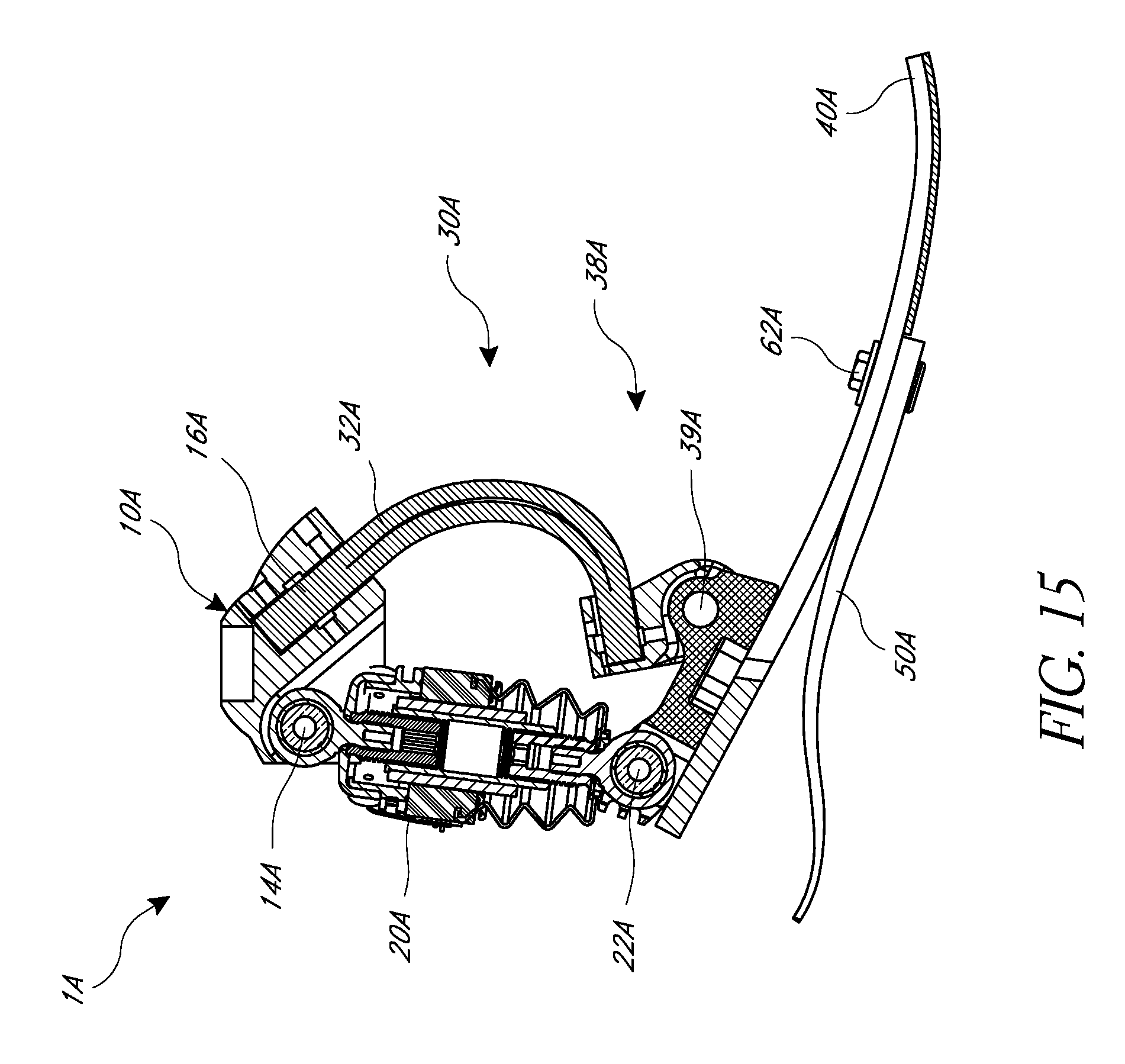
D00013
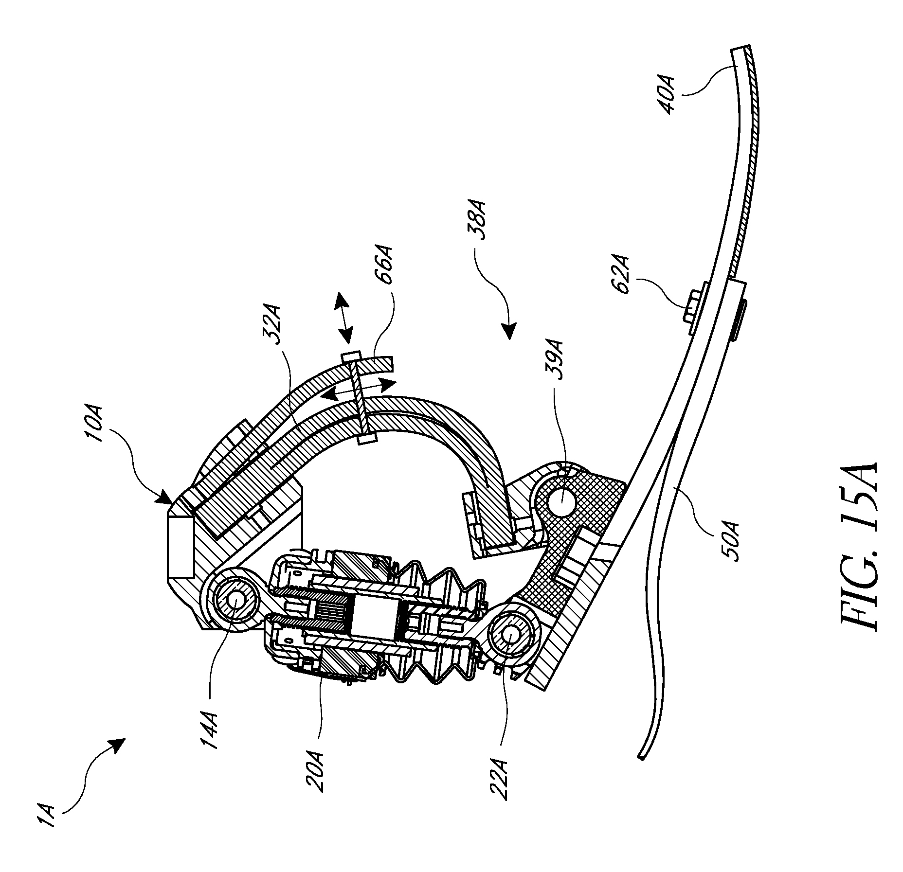
D00014
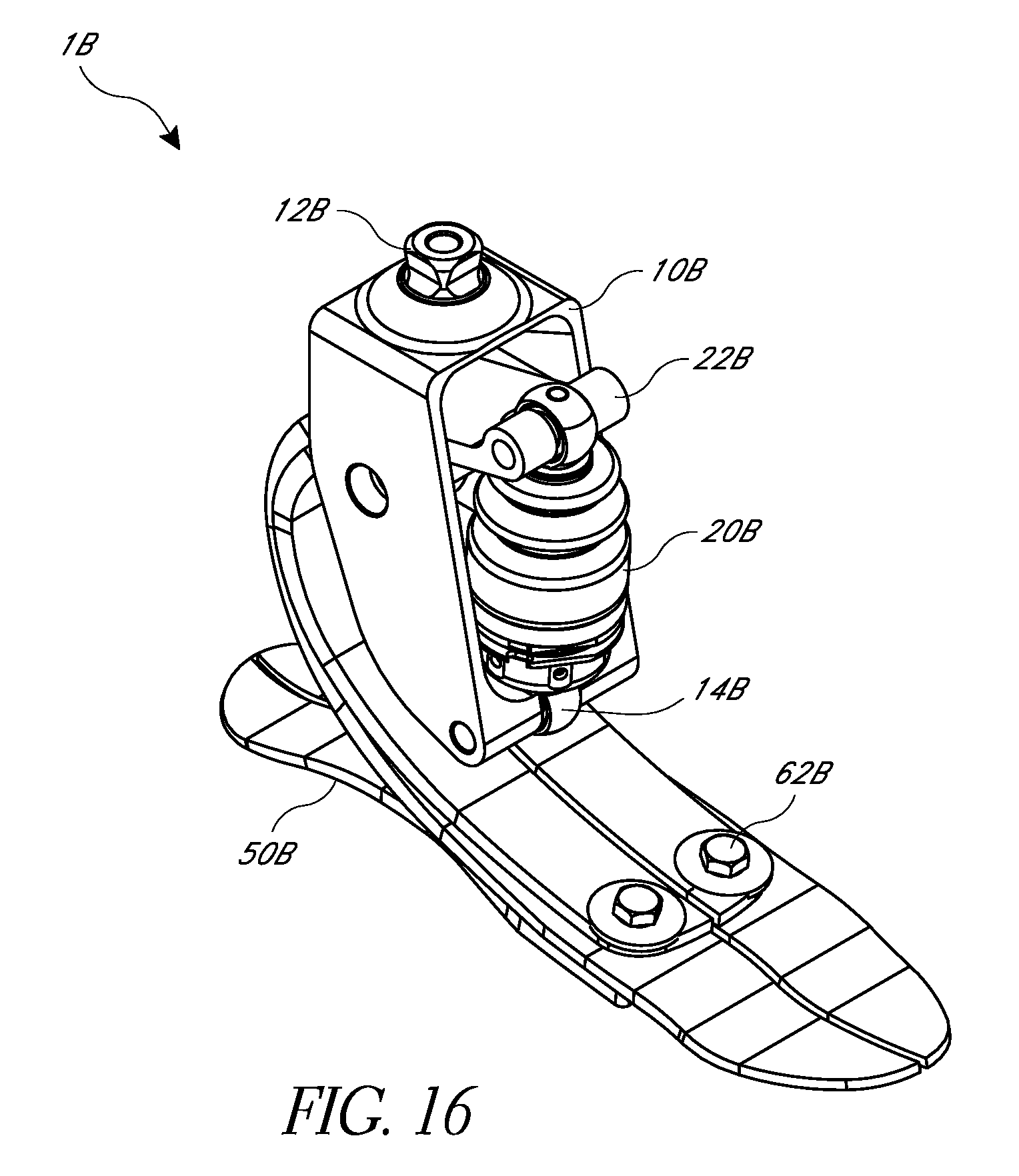
D00015
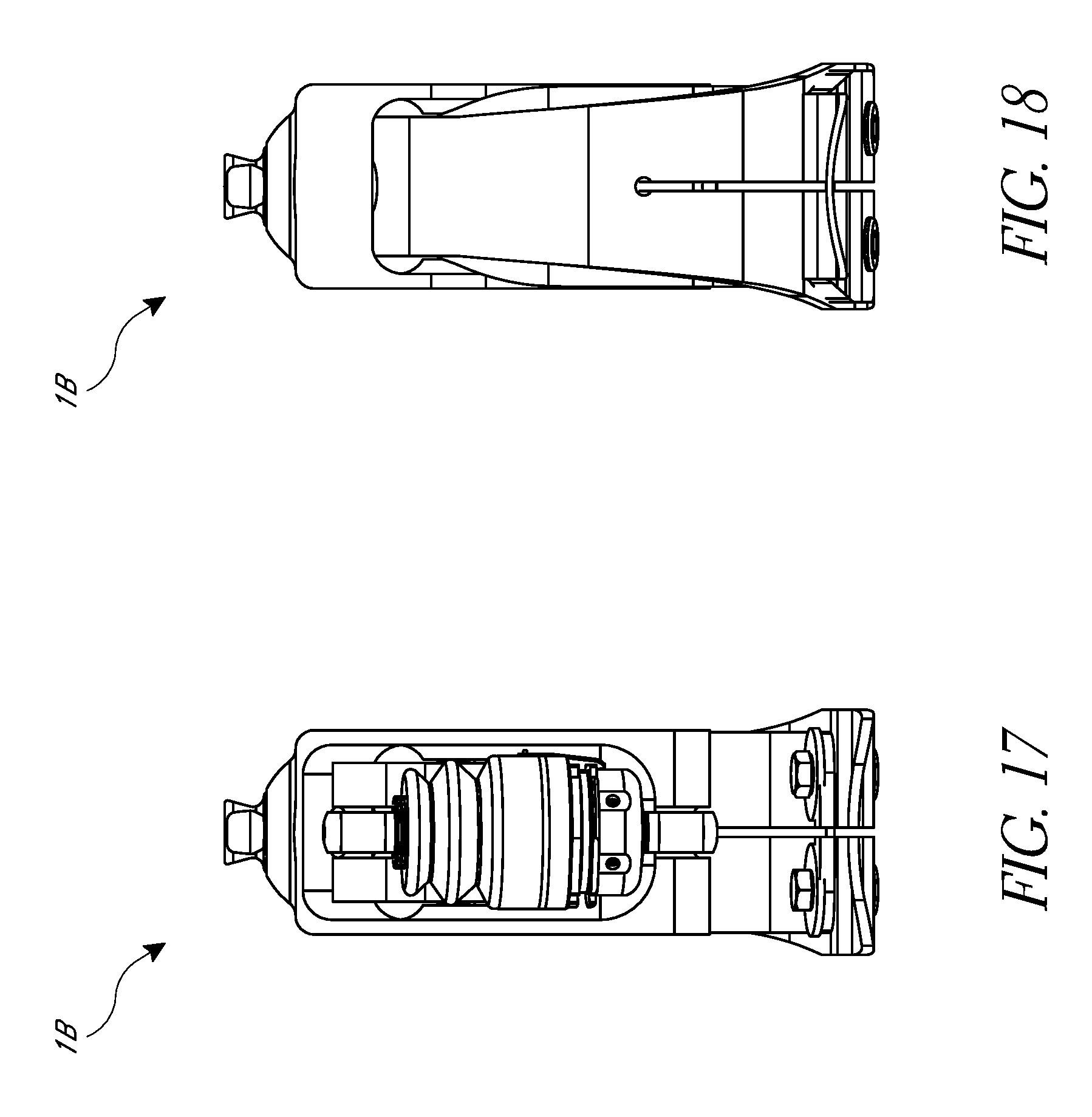
D00016
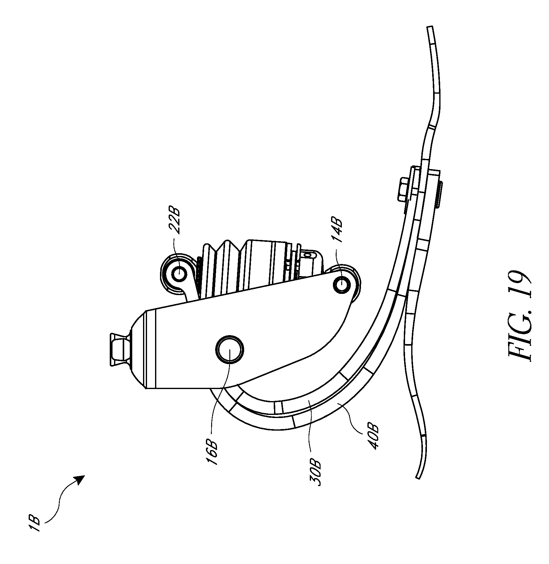
D00017
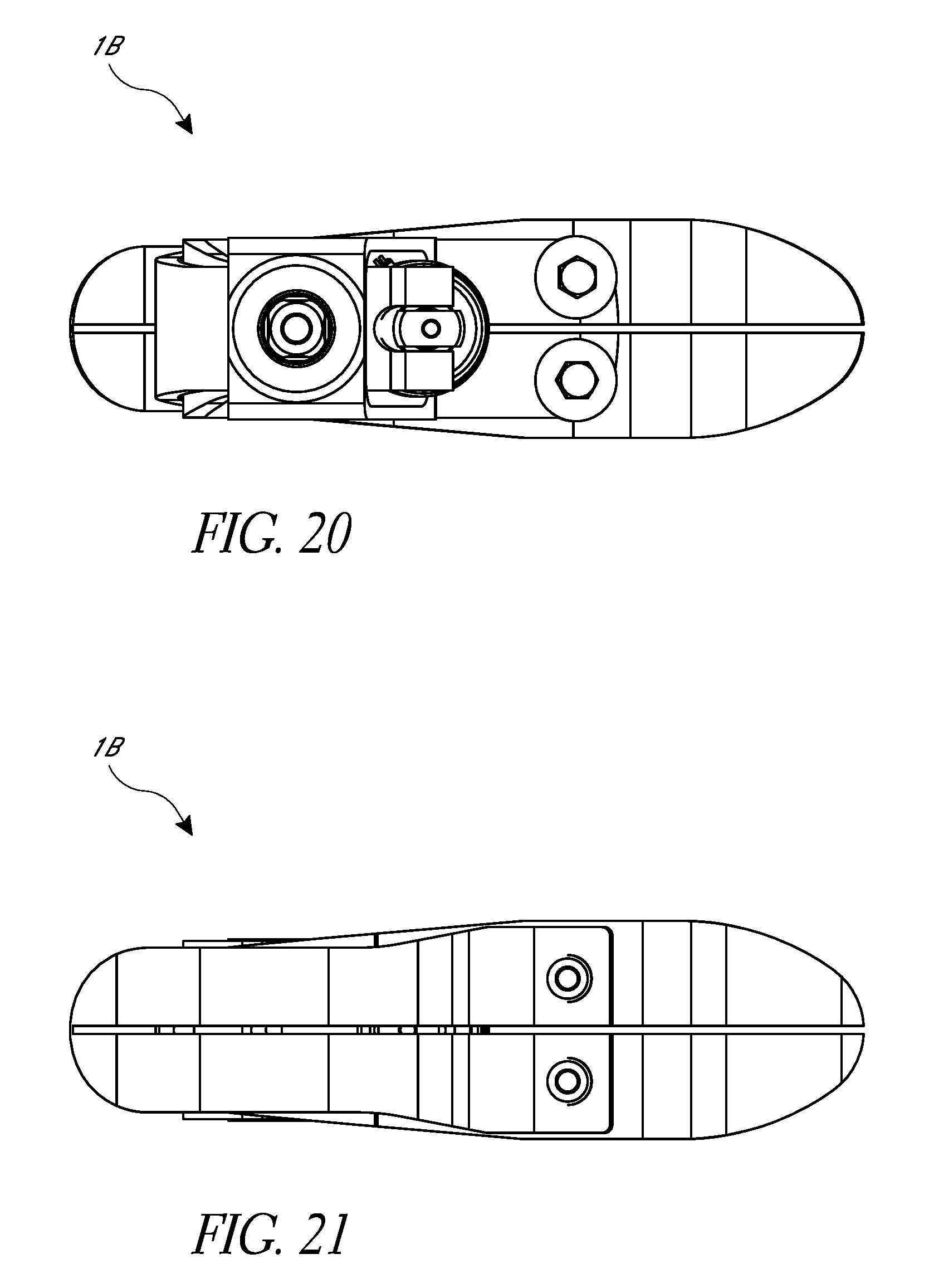
D00018
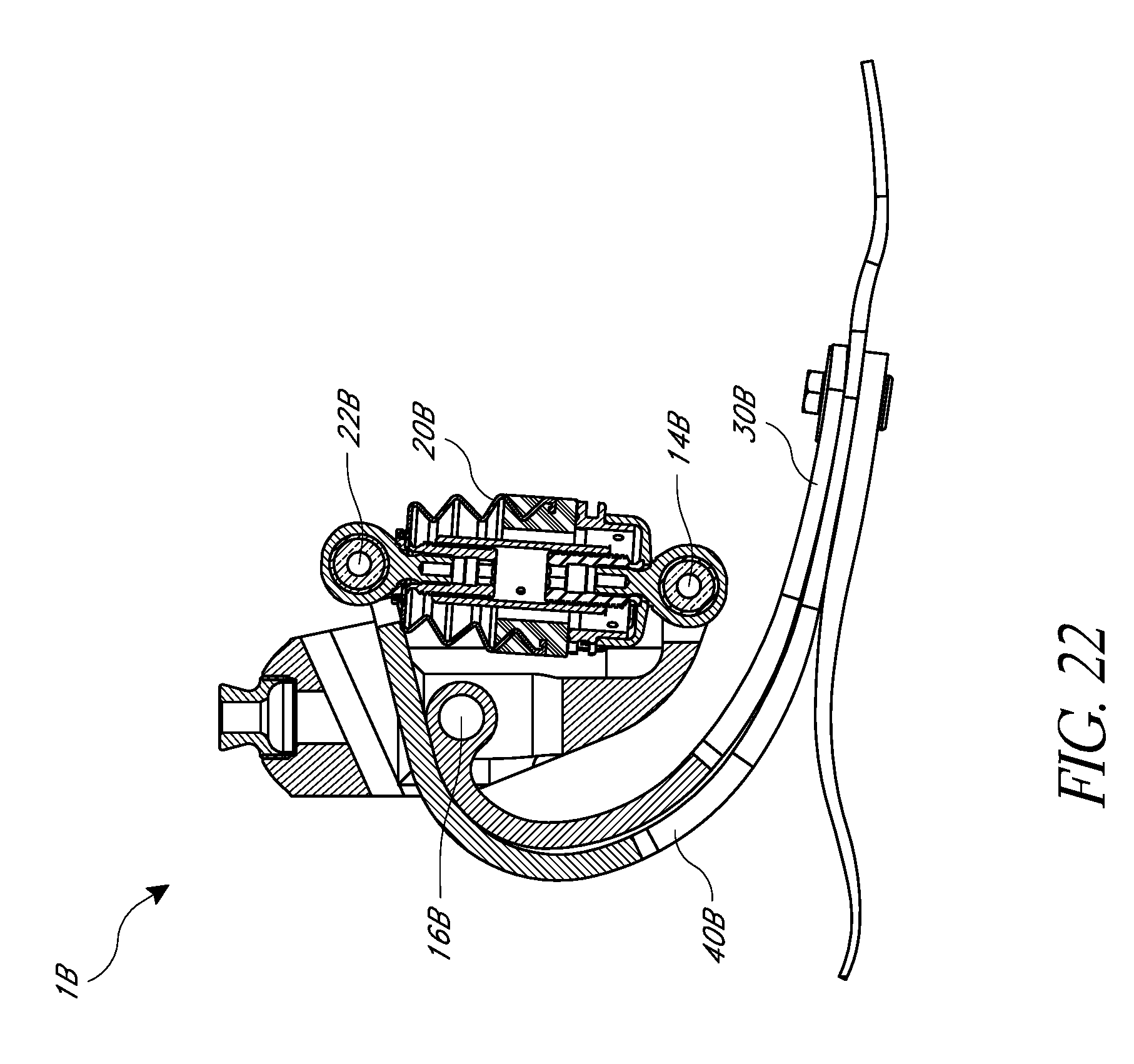
D00019
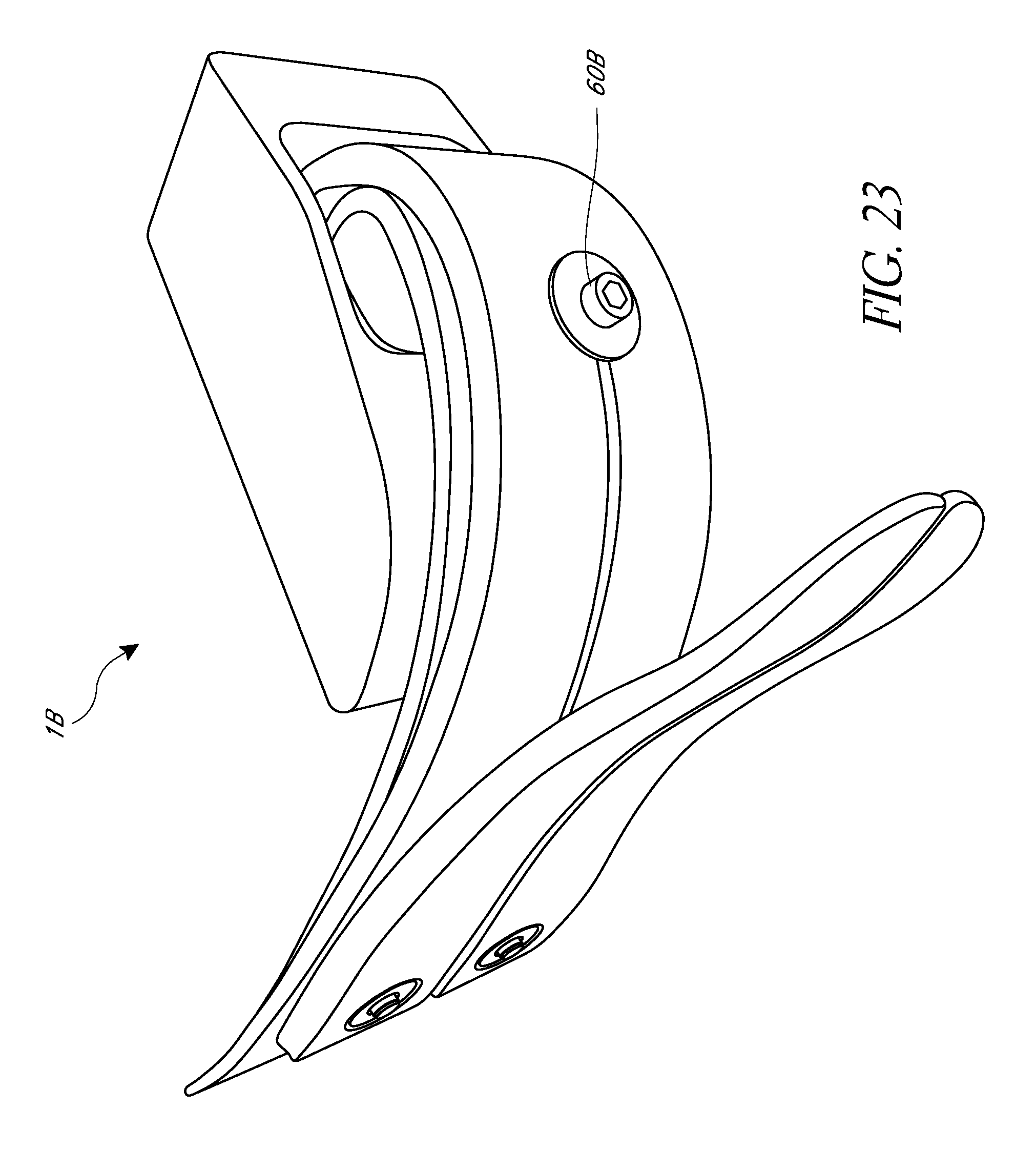
XML
uspto.report is an independent third-party trademark research tool that is not affiliated, endorsed, or sponsored by the United States Patent and Trademark Office (USPTO) or any other governmental organization. The information provided by uspto.report is based on publicly available data at the time of writing and is intended for informational purposes only.
While we strive to provide accurate and up-to-date information, we do not guarantee the accuracy, completeness, reliability, or suitability of the information displayed on this site. The use of this site is at your own risk. Any reliance you place on such information is therefore strictly at your own risk.
All official trademark data, including owner information, should be verified by visiting the official USPTO website at www.uspto.gov. This site is not intended to replace professional legal advice and should not be used as a substitute for consulting with a legal professional who is knowledgeable about trademark law.