Neural measurement
Single
U.S. patent number 10,368,762 [Application Number 15/307,770] was granted by the patent office on 2019-08-06 for neural measurement. This patent grant is currently assigned to Saluda Medical Pty Ltd.. The grantee listed for this patent is Saluda Medical Pty Ltd. Invention is credited to Peter Scott Vallack Single.


| United States Patent | 10,368,762 |
| Single | August 6, 2019 |
Neural measurement
Abstract
Measuring a neural response to a stimulus comprises applying an electrical stimulus, then imposing a delay during which the stimulus electrodes are open circuited. During the delay, a neural response signal present at sense electrodes is measured with a measurement amplifier, while ensuring that an impedance between the sense electrodes is sufficiently large that a voltage arising on the sense electrode tissue interface in response to the stimulus is constrained to a level which permits assessment of the neural response voltage seen at the sense electrode. For example the input impedance to the measurement amplifier (Z.sub.IN) can be >.times..times..times..times..times. ##EQU00001## where Z.sub.C is the sense electrode(s) constant phase element impedance, V.sub.s1-V.sub.s2 is the differential voltage arising on the sense electrode tissue interface, and V.sub.E is the neural response voltage seen at the sense electrode.
| Inventors: | Single; Peter Scott Vallack (Artarmon, AU) | ||||||||||
|---|---|---|---|---|---|---|---|---|---|---|---|
| Applicant: |
|
||||||||||
| Assignee: | Saluda Medical Pty Ltd.
(Artarmon, AU) |
||||||||||
| Family ID: | 54391860 | ||||||||||
| Appl. No.: | 15/307,770 | ||||||||||
| Filed: | May 5, 2015 | ||||||||||
| PCT Filed: | May 05, 2015 | ||||||||||
| PCT No.: | PCT/AU2015/050215 | ||||||||||
| 371(c)(1),(2),(4) Date: | October 28, 2016 | ||||||||||
| PCT Pub. No.: | WO2015/168735 | ||||||||||
| PCT Pub. Date: | November 12, 2015 |
Prior Publication Data
| Document Identifier | Publication Date | |
|---|---|---|
| US 20170049345 A1 | Feb 23, 2017 | |
Foreign Application Priority Data
| May 5, 2014 [AU] | 2014901639 | |||
| Current U.S. Class: | 1/1 |
| Current CPC Class: | A61B 5/7203 (20130101); A61N 1/0551 (20130101); A61B 5/04004 (20130101); A61N 1/36135 (20130101); A61B 5/04001 (20130101); A61N 1/0529 (20130101); A61N 1/36128 (20130101); A61N 1/0541 (20130101) |
| Current International Class: | A61B 5/00 (20060101); A61N 1/372 (20060101); A61B 5/04 (20060101); A61N 1/36 (20060101); A61N 1/05 (20060101) |
References Cited [Referenced By]
U.S. Patent Documents
| 3736434 | May 1973 | Darrow |
| 3817254 | June 1974 | Maurer |
| 3898472 | August 1975 | Long |
| 4158196 | June 1979 | Crawford, Jr. |
| 4418695 | December 1983 | Buffet |
| 4474186 | October 1984 | Ledley et al. |
| 4628934 | December 1986 | Pohndorf et al. |
| 4807643 | February 1989 | Rosier |
| 4856525 | August 1989 | Van Den et al. |
| 5113859 | May 1992 | Funke |
| 5139020 | August 1992 | Koestner et al. |
| 5143081 | September 1992 | Young et al. |
| 5156154 | October 1992 | Valenta, Jr. et al. |
| 5172690 | December 1992 | Nappholz et al. |
| 5184615 | February 1993 | Nappholz et al. |
| 5188106 | February 1993 | Nappholz et al. |
| 5215100 | June 1993 | Spitz |
| 5324311 | June 1994 | Acken |
| 5417719 | May 1995 | Hull et al. |
| 5431693 | July 1995 | Schroeppel |
| 5458623 | October 1995 | Lu et al. |
| 5476486 | December 1995 | Lu et al. |
| 5497781 | March 1996 | Chen et al. |
| 5638825 | June 1997 | Yamazaki et al. |
| 5702429 | December 1997 | King et al. |
| 5758651 | June 1998 | Nygard et al. |
| 5776170 | July 1998 | Macdonald et al. |
| 5785651 | July 1998 | Kuhn et al. |
| 5792212 | August 1998 | Weijand et al. |
| 5814092 | September 1998 | King |
| 5913882 | June 1999 | King |
| 5999848 | December 1999 | Gord et al. |
| 6020857 | February 2000 | Podger |
| 6027456 | February 2000 | Feler et al. |
| 6038480 | March 2000 | Hrdlicka et al. |
| 6066163 | May 2000 | John |
| 6114164 | September 2000 | Dennis et al. |
| 6144881 | November 2000 | Hemming et al. |
| 6157861 | December 2000 | Faltys et al. |
| 6212431 | April 2001 | Hahn et al. |
| 6246912 | June 2001 | Sluijter et al. |
| 6381496 | April 2002 | Meadows et al. |
| 6463328 | October 2002 | John |
| 6473649 | October 2002 | Gryzwa et al. |
| 6473653 | October 2002 | Schallhorn et al. |
| 6493576 | December 2002 | Dankwart-Eder |
| 6522932 | February 2003 | Kuzma |
| 6600955 | July 2003 | Zierhofer et al. |
| 6658293 | December 2003 | Vonk et al. |
| 6675046 | January 2004 | Holsheimer |
| 6782292 | August 2004 | Whitehurst |
| 6898582 | May 2005 | Lange et al. |
| 7089059 | August 2006 | Pless |
| 7171261 | January 2007 | Litvak et al. |
| 7231254 | June 2007 | DiLorenzo et al. |
| 7286876 | October 2007 | Yonce et al. |
| 7412287 | August 2008 | Yonce et al. |
| 7450992 | November 2008 | Cameron |
| 7734340 | June 2010 | De Ridder |
| 7742810 | June 2010 | Moffitt |
| 7792584 | September 2010 | Van Oort et al. |
| 7818052 | October 2010 | Litvak et al. |
| 7831305 | November 2010 | Gliner |
| 7835804 | November 2010 | Fridman et al. |
| 8190251 | May 2012 | Molnar et al. |
| 8224459 | July 2012 | Pianca et al. |
| 8239031 | August 2012 | Fried et al. |
| 8359102 | January 2013 | Thacker et al. |
| 8454529 | June 2013 | Daly et al. |
| 8494645 | July 2013 | Spitzer et al. |
| 8588929 | November 2013 | Davis et al. |
| 8670830 | March 2014 | Carlson et al. |
| 8886323 | November 2014 | Wu et al. |
| 9155892 | October 2015 | Parker et al. |
| 9302112 | April 2016 | Bornzin et al. |
| 9381356 | July 2016 | Parker et al. |
| 9386934 | July 2016 | Parker et al. |
| 9872990 | January 2018 | Parker et al. |
| 9974455 | May 2018 | Parker et al. |
| 10206596 | February 2019 | Single et al. |
| 2002/0055688 | May 2002 | Katims |
| 2002/0099419 | July 2002 | Ayal Shai et al. |
| 2002/0193670 | December 2002 | Garfield et al. |
| 2003/0032889 | February 2003 | Wells |
| 2003/0045909 | March 2003 | Gross et al. |
| 2003/0139781 | July 2003 | Bradley et al. |
| 2003/0195580 | October 2003 | Bradley et al. |
| 2004/0088017 | May 2004 | Sharma et al. |
| 2004/0122482 | June 2004 | Tung et al. |
| 2004/0158298 | August 2004 | Gliner |
| 2004/0225211 | November 2004 | Gozani et al. |
| 2004/0254494 | December 2004 | Spokoyny et al. |
| 2005/0010265 | January 2005 | Baru Fassio |
| 2005/0017190 | January 2005 | Eversmann et al. |
| 2005/0021104 | January 2005 | DiLorenzo |
| 2005/0065427 | March 2005 | Magill |
| 2005/0070982 | March 2005 | Heruth et al. |
| 2005/0075683 | April 2005 | Miesel et al. |
| 2005/0101878 | May 2005 | Daly |
| 2005/0113877 | May 2005 | Giardiello et al. |
| 2005/0137670 | June 2005 | Christopherson et al. |
| 2005/0149154 | July 2005 | Cohen |
| 2005/0192567 | September 2005 | Katims |
| 2005/0203600 | September 2005 | Wallace |
| 2005/0209655 | September 2005 | Bradley et al. |
| 2005/0282149 | December 2005 | Kovacs et al. |
| 2006/0009820 | January 2006 | Royle et al. |
| 2006/0020291 | January 2006 | Gozani |
| 2006/0135998 | June 2006 | Libbus et al. |
| 2006/0195159 | August 2006 | Bradley et al. |
| 2006/0212089 | September 2006 | Tass |
| 2006/0217782 | September 2006 | Boveja et al. |
| 2006/0264752 | November 2006 | Rubinsky et al. |
| 2006/0287609 | December 2006 | Litvak et al. |
| 2007/0021800 | January 2007 | Bradley Kerry et al. |
| 2007/0073354 | March 2007 | Knudson et al. |
| 2007/0100378 | May 2007 | Maschino |
| 2007/0178579 | August 2007 | Ross et al. |
| 2007/0185409 | August 2007 | Wu et al. |
| 2007/0208394 | September 2007 | King et al. |
| 2007/0225767 | September 2007 | Daly et al. |
| 2007/0244410 | October 2007 | Fridman et al. |
| 2007/0250120 | October 2007 | Flach et al. |
| 2007/0255372 | November 2007 | Metzler et al. |
| 2007/0282217 | December 2007 | McGinnis et al. |
| 2007/0287931 | December 2007 | Dilorenzo |
| 2008/0021292 | January 2008 | Stypulkowski |
| 2008/0051647 | February 2008 | Wu et al. |
| 2008/0064947 | March 2008 | Heruth et al. |
| 2008/0077191 | March 2008 | Morrell |
| 2008/0097529 | April 2008 | Parramon et al. |
| 2008/0147155 | June 2008 | Swoyer |
| 2008/0183076 | July 2008 | Witte |
| 2008/0208304 | August 2008 | Zdravkovic et al. |
| 2008/0234780 | September 2008 | Smith et al. |
| 2008/0275527 | November 2008 | Greenberg et al. |
| 2008/0294221 | November 2008 | Kilgore |
| 2008/0300655 | December 2008 | Cholette |
| 2009/0033486 | February 2009 | Costantino et al. |
| 2009/0082691 | March 2009 | Denison et al. |
| 2009/0157155 | June 2009 | Bradley |
| 2009/0270957 | October 2009 | Pianca |
| 2009/0287277 | November 2009 | Conn et al. |
| 2009/0299214 | December 2009 | Wu et al. |
| 2009/0306491 | December 2009 | Haggers |
| 2010/0010388 | January 2010 | Panken et al. |
| 2010/0058126 | March 2010 | Chang et al. |
| 2010/0069835 | March 2010 | Parker |
| 2010/0069996 | March 2010 | Strahl |
| 2010/0070007 | March 2010 | Parker |
| 2010/0070008 | March 2010 | Parker |
| 2010/0106231 | April 2010 | Torgerson |
| 2010/0114258 | May 2010 | Donofrio et al. |
| 2010/0125313 | May 2010 | Lee et al. |
| 2010/0125314 | May 2010 | Bradley et al. |
| 2010/0145222 | June 2010 | Brunnett et al. |
| 2010/0152808 | June 2010 | Boggs |
| 2010/0179626 | July 2010 | Pilarski |
| 2010/0191307 | July 2010 | Fang et al. |
| 2010/0204748 | August 2010 | Lozano et al. |
| 2010/0222844 | September 2010 | Troosters et al. |
| 2010/0222858 | September 2010 | Meloy |
| 2010/0249643 | September 2010 | Gozani et al. |
| 2010/0249867 | September 2010 | Wanasek |
| 2010/0258342 | October 2010 | Parker |
| 2010/0262208 | October 2010 | Parker |
| 2010/0262214 | October 2010 | Robinson |
| 2010/0280570 | November 2010 | Sturm et al. |
| 2010/0286748 | November 2010 | Midani et al. |
| 2010/0331604 | December 2010 | Okamoto et al. |
| 2010/0331926 | December 2010 | Lee et al. |
| 2011/0004207 | January 2011 | Wallace et al. |
| 2011/0021943 | January 2011 | Lacour et al. |
| 2011/0028859 | February 2011 | Chian |
| 2011/0087085 | April 2011 | Tsampazis et al. |
| 2011/0093042 | April 2011 | Torgerson et al. |
| 2011/0106100 | May 2011 | Bischoff |
| 2011/0184488 | July 2011 | De Ridder et al. |
| 2011/0204811 | August 2011 | Pollmann-retsch |
| 2011/0224749 | September 2011 | Ben-David et al. |
| 2011/0264165 | October 2011 | Molnar et al. |
| 2011/0270343 | November 2011 | Buschman et al. |
| 2011/0313310 | December 2011 | Tomita |
| 2011/0313483 | December 2011 | Hincapie et al. |
| 2012/0029377 | February 2012 | Polak |
| 2012/0101552 | April 2012 | Lazarewicz et al. |
| 2012/0109236 | May 2012 | Jacobson et al. |
| 2012/0253423 | October 2012 | Youn et al. |
| 2012/0277621 | November 2012 | Gerber et al. |
| 2012/0277823 | November 2012 | Gerber et al. |
| 2013/0053722 | February 2013 | Carlson et al. |
| 2013/0060302 | March 2013 | Polefko et al. |
| 2013/0172774 | July 2013 | Crowder et al. |
| 2013/0289661 | October 2013 | Griffith et al. |
| 2013/0289683 | October 2013 | Parker et al. |
| 2014/0066803 | March 2014 | Choi |
| 2014/0142447 | May 2014 | Takahashi |
| 2014/0194771 | July 2014 | Parker et al. |
| 2014/0194772 | July 2014 | Single et al. |
| 2014/0236042 | August 2014 | Parker et al. |
| 2014/0236257 | August 2014 | Parker et al. |
| 2014/0243926 | August 2014 | Carcieri |
| 2014/0243931 | August 2014 | Parker et al. |
| 2014/0276195 | September 2014 | Papay et al. |
| 2014/0277250 | September 2014 | Su et al. |
| 2014/0288551 | September 2014 | Bharmi et al. |
| 2014/0288577 | September 2014 | Robinson et al. |
| 2014/0296737 | October 2014 | Parker et al. |
| 2014/0358024 | December 2014 | Nelson et al. |
| 2015/0018699 | January 2015 | Zeng et al. |
| 2015/0164354 | June 2015 | Parker et al. |
| 2015/0174396 | June 2015 | Fisher et al. |
| 2015/0238104 | August 2015 | Tass |
| 2015/0238304 | August 2015 | Lamraoui |
| 2015/0282725 | October 2015 | Single |
| 2015/0313487 | November 2015 | Single |
| 2015/0360031 | December 2015 | Bornzin et al. |
| 2015/0374999 | December 2015 | Parker |
| 2016/0166164 | June 2016 | Obradovic et al. |
| 2016/0287126 | October 2016 | Parker et al. |
| 2016/0287182 | October 2016 | Single |
| 2017/0001017 | January 2017 | Parker et al. |
| 2017/0071490 | March 2017 | Parker et al. |
| 2017/0135624 | May 2017 | Parker |
| 2017/0216587 | August 2017 | Parker |
| 2017/0361101 | December 2017 | Single |
| 2018/0110987 | April 2018 | Parker |
| 2018/0117335 | May 2018 | Parker et al. |
| 2018/0132747 | May 2018 | Parker et al. |
| 2018/0132760 | May 2018 | Parker |
| 2018/0133459 | May 2018 | Parker et al. |
| 2018/0228391 | August 2018 | Parker et al. |
| 2018/0228547 | August 2018 | Parker |
| 2018/0229046 | August 2018 | Parker et al. |
| 2018/0256052 | September 2018 | Parker et al. |
| 0219084 | Apr 1987 | EP | |||
| 0998958 | Aug 2005 | EP | |||
| 2019716 | Nov 2007 | EP | |||
| 2243510 | Oct 2010 | EP | |||
| 2443995 | Apr 2012 | EP | |||
| 2013527784 | Jul 2013 | JP | |||
| 1983003191 | Sep 1983 | WO | |||
| 1993001863 | Feb 1993 | WO | |||
| 9612383 | Apr 1996 | WO | |||
| 2000002623 | Jan 2000 | WO | |||
| 2002036003 | Nov 2001 | WO | |||
| 2002038031 | May 2002 | WO | |||
| 2002049500 | Jun 2002 | WO | |||
| 2003028521 | Apr 2003 | WO | |||
| 2003043690 | May 2003 | WO | |||
| 2003103484 | Dec 2003 | WO | |||
| 2004021885 | Mar 2004 | WO | |||
| 20040103455 | Dec 2004 | WO | |||
| 2005032656 | Apr 2005 | WO | |||
| 2005105202 | Nov 2005 | WO | |||
| 2006091636 | Aug 2006 | WO | |||
| 2007064936 | Jun 2007 | WO | |||
| 2007127926 | Nov 2007 | WO | |||
| 2007130170 | Nov 2007 | WO | |||
| 2008004204 | Jan 2008 | WO | |||
| 2008049199 | May 2008 | WO | |||
| 2009002072 | Dec 2008 | WO | |||
| 2009002579 | Dec 2008 | WO | |||
| 2009010870 | Jan 2009 | WO | |||
| 2009130515 | Oct 2009 | WO | |||
| 2009146427 | Dec 2009 | WO | |||
| 2010013170 | Feb 2010 | WO | |||
| 2010044989 | Apr 2010 | WO | |||
| 2010051392 | May 2010 | WO | |||
| 2010057046 | May 2010 | WO | |||
| 2010124139 | Oct 2010 | WO | |||
| 2010138915 | Dec 2010 | WO | |||
| 2011011327 | Jan 2011 | WO | |||
| 2011066477 | Jun 2011 | WO | |||
| 2011066478 | Jun 2011 | WO | |||
| 2011112843 | Sep 2011 | WO | |||
| 2011119251 | Sep 2011 | WO | |||
| 2011159545 | Dec 2011 | WO | |||
| 2012027791 | Mar 2012 | WO | |||
| 2012155183 | Nov 2012 | WO | |||
| 2012155184 | Nov 2012 | WO | |||
| 2012155185 | Nov 2012 | WO | |||
| 2012155187 | Nov 2012 | WO | |||
| 2012155188 | Nov 2012 | WO | |||
| 2012155189 | Nov 2012 | WO | |||
| 2012155190 | Nov 2012 | WO | |||
| WO 2012155183 | Nov 2012 | WO | |||
| 2013063111 | May 2013 | WO | |||
| 2013075171 | May 2013 | WO | |||
| 2014071445 | May 2014 | WO | |||
| 2014071446 | May 2014 | WO | |||
| 2014143577 | Sep 2014 | WO | |||
| 2015070281 | May 2015 | WO | |||
| 2015074121 | May 2015 | WO | |||
| 2015109239 | Jul 2015 | WO | |||
| 2015143509 | Oct 2015 | WO | |||
| 2015168735 | Nov 2015 | WO | |||
| 20160011512 | Jan 2016 | WO | |||
| 2016077882 | May 2016 | WO | |||
| 2016090420 | Jun 2016 | WO | |||
| 2016090436 | Jun 2016 | WO | |||
| 2016115596 | Jul 2016 | WO | |||
| 2016161484 | Oct 2016 | WO | |||
| 2016191807 | Dec 2016 | WO | |||
| 2016191808 | Dec 2016 | WO | |||
| 2016191815 | Dec 2016 | WO | |||
| 2017173493 | Oct 2017 | WO | |||
| 2017219096 | Dec 2017 | WO | |||
Other References
|
Al-Ani et al., "Automatic removal of high-amplitude stimulus artefact from neuronal signal recorded in the subthalamic nucleus", Journal of Neuroscience Methods, vol. 198, Issue 1, 2011, pp. 135-146. cited by applicant . European Search Report for European Application 12785619.3 Search Completed Oct. 13, 2014, dated Oct. 23, 2014, 7 pgs. cited by applicant . European Search Report for European Application 12785669.8 Search Completed Sep. 22, 2014, dated Sep. 29, 2014, 5 pgs. cited by applicant . Extended European Search Report for EP Application 12785483.4 completed Sep. 16, 2014, 7 pgs. cited by applicant . Extended European Search Report for European Application No. 11820923.8, report completed Dec. 9, 2013, report dated Dec. 17, 2013, 6 pgs. cited by applicant . Extended European Search Report for European Application No. 13852669.4, Search completed Jun. 8, 2016, dated Jun. 22, 2016, 09 pgs. cited by applicant . Extended European Search Report for European Application No. 14861553.7, Search completed Jun. 8, 2017, dated Jun. 19, 2017, 8 pgs. cited by applicant . Extended European Search Report for European Application No. 14863597.2, Search completed Jun. 6, 2017, dated Jun. 13, 2017, 9 pgs. cited by applicant . Extended European Search Report for European Application No. 13853514.1, Search completed Jun. 8, 2016, dated Jun. 15, 2016, 07 pgs. cited by applicant . International Preliminary Report on Patentability for International Application No. PCT/AU2012/001441, Report dated May 27, 2014, 10 pgs. cited by applicant . International Search Report and Written Opinion for International Application No. PCT/AU2011/001127, date completed Nov. 11, 2011, dated Nov. 15, 2011, 13 pgs. cited by applicant . International Search Report and Written Opinion for International Application No. PCT/AU2012/001441, International Filing Date Nov. 23, 2012, Search Completed Feb. 26, 2013, dated Feb. 26, 2013, 14 pgs. cited by applicant . International Search Report and Written Opinion for International Application No. PCT/AU2014/001049, Search completed Feb. 10, 2015, dated Feb. 10, 2015, 8 pgs. cited by applicant . International Search Report and Written Opinion for International Application No. PCT/AU2014/050369, Search completed Feb. 20, 2015, dated Feb. 20, 2015, 14 pgs. cited by applicant . International Search Report and Written Opinion for International Application No. PCT/AU2015/050135, Search completed Jun. 30, 2015, dated Jun. 30, 2015, 26 pgs. cited by applicant . International Search Report and Written Opinion for International Application No. PCT/AU2015/050422, Search completed Oct. 14, 2015, dated Oct. 14, 2015, 17 pgs. cited by applicant . International Search Report and Written Opinion for International Application No. PCT/AU2015/050724, Search completed May 9, 2016, dated May 9, 2016, 8 pgs. cited by applicant . International Search Report and Written Opinion for International Application No. PCT/AU2015/050753, Search completed Feb. 10, 2016, dated Feb. 10, 2016, 10 pgs. cited by applicant . International Search Report and Written Opinion for International Application No. PCT/AU2015/050787, Search completed Mar. 16, 2016, dated Mar. 16, 2016, 10 pgs. cited by applicant . International Search Report and Written Opinion for International Application No. PCT/AU2016/050019, Search completed May 4, 2016, dated May 4, 2016, 16 pgs. cited by applicant . International Search Report for Australian Application 2011901829 Search Completed Feb. 6, 2012, dated Feb. 7, 2012, 3 pgs. cited by applicant . International Search Report for International Application No. PCT/AU2012/000511, International Filing Date May 11, 2012, Search Completed May 17, 2012, dated May 18, 2012, 4 pgs. cited by applicant . International Search Report for International Application No. PCT/AU2012/000512, International Filing Date May 11, 2012, Search Completed Jul. 10, 2012, dated Jul. 11, 2012, 4 pgs. cited by applicant . International Search Report for International Application No. PCT/AU2012/000513, International Filing Date May 11, 2012, Search Completed May 29, 2012, dated May 30, 2012, 5 pgs. cited by applicant . International Search Report for International Application No. PCT/AU2012/000515, International Filing Date May 11, 2012, Search Completed May 21, 2012, dated Jun. 4, 2012, 5 pgs. cited by applicant . International Search Report for International Application No. PCT/AU2012/000516, International Filing Date May 11, 2012, Search Completed Jul. 11, 2012, dated Jul. 12, 2012, 8 pgs. cited by applicant . International Search Report for International Application No. PCT/AU2012/000517, International Filing Date May 11, 2012, Search Completed Jun. 4, 2012, dated Jun. 6, 2012, 3 pgs. cited by applicant . International Search Report for International Application No. PCT/AU2012/000518, International Filing Date May 11, 2012, Search Completed Jun. 8, 2012, dated Jun. 12, 2012, 4 pgs. cited by applicant . Medtronic, Spinal Cord Stimulation, RestoreSensor Neurostimulator, Features and Specification: Specification, Printed Jun. 16, 2014, 2 pgs. cited by applicant . Medtronic, Spinal Cord Stimulation, RestoreSensor Neurostimulator, Features and Specification: Summary Printed Jun. 16, 2014, 1 pg. cited by applicant . Written Opinion for International Application No. PCT/AU2012/000511, International Filing Date May 11, 2012, Search Completed May 17, 2012, dated May 18, 2012, 5 pgs. cited by applicant . Written Opinion for International Application No. PCT/AU2012/000512, International Filing Date May 11, 2012, Search Completed Jul. 10, 2012, dated Jul. 11, 2012, 7 pgs. cited by applicant . Written Opinion for International Application No. PCT/AU2012/000513, International Filing Date May 11, 2012, Search Completed May 29, 2012, dated May 30, 2012, 10 pgs. cited by applicant . Written Opinion for International Application No. PCT/AU2012/000515, International Filing Date May 11, 2012, Search Completed May 21, 2012, dated Jun. 4, 2012, 4 pgs. cited by applicant . Written Opinion for International Application No. PCT/AU2012/000516, International Filing Date May 11, 2012, Search Completed Jul. 11, 2012, dated Jul. 12, 2012, 8 pgs. cited by applicant . Written Opinion for International Application No. PCT/AU2012/000517, International Filing Date May 11, 2012, Search Completed Jun. 4, 2012, dated Jun. 6, 2012, 5 pgs. cited by applicant . Written Opinion for International Application No. PCT/AU2012/000518, International Filing Date May 11, 2012, Search Completed Jun. 8, 2012, dated Jun. 12, 2012, 10 pgs. cited by applicant . Medtronic, RestoreSensor Neurostimulator, Retrieved from: http://web.archive.org/web/20150328092923/http://professional.medtronic.c- om:80/pt/neuro/scs/prod/restore-sensor/features-specifications/index.htm, Capture Date Jul. 9, 2012, Printed on May 11, 2017. cited by applicant . "Advanced Pain Therapy using Neurostimulation for Chronic Pain", Medtronic RestoreSensor clinical trial paper,Clinical summary, Nov. 2011, pp. 32. cited by applicant . "Battelle Neurotechnology--Moving Beyond the Limits in Neurotechnology", Battelle, www.battelle.org, May 2014, pp. 1-2. cited by applicant . "Haptic technology", Wkipedia, Retrieved from: http://en.wikipedia.org/wiki/Haptic_technology, Last modified on Sep. 15, 2014, Printed on Sep. 15, 2014, 5 pgs. cited by applicant . "Implants for surgery, Cardiac pacemakers", IS-1 standard ISO 5841-3-2000, Oct. 15, 2000. cited by applicant . International Search Report & Written Opinion for International Application No. PCT/AU2013/001280, Search Completed Jan. 16, 2014, dated Jan. 16, 2014, 8 pgs. cited by applicant . International Search Report & Written Opinion for International Application PCT/AU2013/001279, Search Completed Jan. 9, 2014, dated Jan. 9, 2014, 9 pgs. cited by applicant . "Neural Bypass Technology Enables Movement in Paralyzed Patient", Posted on Jul. 29, 2014, 6 a.m. in Brain chips/computer interface, pp. 1-2. cited by applicant . "Spinal Cord Stimulation, About Spinal Cord Stimulation", Medtronic, Retrieved from: http://professional.medtronic.com/pt/neuro/scs/edu/about/index.htm, Printed on Jun. 16, 2014, 2 pgs. cited by applicant . Andreassen, S. et al., "Muscle Fibre Conduction Velocity in Motor Units of the Human Anterior Tibial Muscle: a New Size Principle Parameter", J. Physiol, (1987), 391, pp. 561-571. cited by applicant . Andy, "Parafascicular-Center Median Nuclei Stimulation for Intractable Pain and Dyskinesia (Painful-Dyskinesia)", Stereotactic and Functional Neurosurgery, Appl. Neurophysiol., 43, No. 3-5, 1980, pp. 133-144. cited by applicant . Balzer et al., "Localization of cervical and cervicomedullary stimulation leads for pain treatment using median nerve somatosensay evoked potential collision testing", Journal of Neurosurgery, Jan. 2011, vol. 114, No. 1: pp. 200-205. cited by applicant . Blum, A. R., "An Electronic System for Extracelluar Neural Stimulation and Recording", Dissertation, Georgia Institute of Technology, Aug. 2007, Retrieved from http://smartech.gatech.edu/handle/1853/16192 on Jan. 30, 2012. cited by applicant . Borg et al., "Conduction velocity and refractory period of single motor nerve fibres in antecedent poliomyelitis", Journal of Neurology, Neurosurgery, and Psychiatry, vol. 50, 1987, 443-446. cited by applicant . Brown et al., "Impact of Deep Brain Stimulation on Upper Limb Askinesia in Parkingson's Disease", Annals of Neurology, 45, No. 4, 1999, pp. 473-488. cited by applicant . Budagavi et al., "Modelling of compound nerve action potentials health and disease", Engineering in Medicine and Biology Society, 1992 14th Annual International Conference of the IEEE. vol. 6. IEEE, 1992. pp. 2600-2601. cited by applicant . Coquery et al., "Backward and forward masking in the perception of cutaneous stimuli", Perception & Psychophysics, 1973, vol. 13.No. 2, pp. 161-163. cited by applicant . International Search Report and Written Opinion for International Application No. PCT/AU2015/050215, Search completed Jul. 30, 2015, dated Jul. 30, 2015, 8 Pgs. cited by applicant . "Wde bandwidth BioAmplifier", http://www.psylab.com/html/default_bioamp.htm, 1-3 pages. cited by applicant . Lempka, Scott, "The Electrode-Tissue Interface During Recording and Stimulation in the Central Nervous System", published May 2010. cited by applicant . Srinivasan, S, "Electrode/Electrolyte Interfaces: Structure and Kinetics of Charge Transfer", Chapter 2, 67 Pages. cited by applicant . International Preliminary Report on Patentability for International Application No. PCT/AU2011/001127, Report dated Mar. 5, 2013, 9 pgs. cited by applicant . International Preliminary Report on Patentability for International Application No. PCT/AU2012/000511, Report dated Nov. 19, 2013, 6 pgs. cited by applicant . International Preliminary Report on Patentability for International Application No. PCT/AU2012/000512, Report dated Nov. 19, 2013, 8 pgs. cited by applicant . International Preliminary Report on Patentability for International Application No. PCT/AU2012/000513, Report dated Nov. 19, 2013, 11 pgs. cited by applicant . International Preliminary Report on Patentability for International Application No. PCT/AU2012/000515, Report dated Nov. 19, 2013, 5 pgs. cited by applicant . International Preliminary Report on Patentability for International Application No. PCT/AU2012/000516, Report dated Nov. 19, 2013, 9 pgs. cited by applicant . International Preliminary Report on Patentability for International Application No. PCT/AU2012/000517, Report dated Nov. 19, 2013, 6 pgs. cited by applicant . International Preliminary Report on Patentability for International Application No. PCT/AU2012/000518, Report dated Nov. 19, 2013, 11 pgs. cited by applicant . International Preliminary Report on Patentability for International Application No. PCT/AU2013/001279, Report dated May 12, 2015, 6 pgs. cited by applicant . International Preliminary Report on Patentability for International Application No. PCT/AU2013/001280, Report dated May 12, 2015, 6 pgs. cited by applicant . International Preliminary Report on Patentability for International Application No. PCT/AU2014/001049, Report dated May 17, 2016, 5 pgs. cited by applicant . International Preliminary Report on Patentability for International Application No. PCT/AU2014/050369, Report dated May 24, 2016, 8 pgs. cited by applicant . International Preliminary Report on Patentability for International Application No. PCT/AU2015/050135, Report dated Oct. 4, 2016, 13 pgs. cited by applicant . International Preliminary Report on Patentability for International Application No. PCT/AU2015/050215, Report dated Nov. 8, 2016, 4 pgs. cited by applicant . International Preliminary Report on Patentability for International Application No. PCT/AU2015/050422, Report dated Jan. 31, 2017, 8 pgs. cited by applicant . International Preliminary Report on Patentability for International Application No. PCT/AU2015/050724, Report dated May 23, 2017, 5 pgs. cited by applicant . International Preliminary Report on Patentability for International Application No. PCT/AU2015/050787, Report dated Jun. 13, 2017, 6 pgs. cited by applicant . International Preliminary Report on Patentability for International Application No. PCT/AU2016/050019, Report dated Jul. 25, 2017, 9 pgs. cited by applicant . International Preliminary Report on Patentability for International Application No. PCT/AU2016/050263, Report dated Oct. 10, 2017, 9 pgs. cited by applicant . International Type Search Report for International Application No. AU 2015902393, Search completed May 16, 2016, dated May 16, 2016, 8 Pgs. cited by applicant . Extended European Search Report for European Application No. 15789515.2, Search completed Dec. 4, 2017, dated Jan. 30, 2018, 7 Pgs. cited by applicant . Extended European Search Report for European Application No. 15768956.3, Search completed Oct. 3, 2017, dated Oct. 10, 2017, 8 Pgs. cited by applicant . International Preliminary Report on Patentability for International Application No. PCT/AU2015/050753, Report dated Jun. 13, 2017, 7 pgs. cited by applicant . International Search Report and Written Opinion for International Application No. PCT/AU2016/050263, Search completed Nov. 16, 2016, dated Nov 16, 2016, 8 Pgs. cited by applicant . International Search Report and Written Opinion for International Application No. PCT/AU2016/050430, Search completed Aug. 16, 2016, dated Aug. 16, 2016, 10 Pgs. cited by applicant . International Search Report and Written Opinion for International Application No. PCT/AU2016/050431, Search completed Aug. 16, 2016, dated Aug. 16, 2016, 11 Pgs. cited by applicant . International Search Report and Written Opinion for International Application No. PCT/AU2016/050439, Search completed Jul. 15, 2016, dated Jul. 15, 2016, 8 Pgs. cited by applicant . Alam et al., "Evaluation of optimal electrode configurations for epidural spinal cord stimulation in cervical spinal cord injured rats", Journal of Neuroscience Methods, Mar. 2015, 28 pgs. cited by applicant . Fisher, "F-Waves--Physiology and Clinical Uses", The Scientific World Journal, (2007) 7, pp. 144-160. cited by applicant . Gad et al., "Development of a multi-electrode array for spinal cord epidural stimulation to facilitate stepping and standing after a complete spinal cord injury in adult rats", Journal of NeuroEngineering and Rehabilitation 2013, 10:2, 18 pgs. cited by applicant . Sayenko et al., "Neuromodulation of evoked muscle potentials induced by epidural spinal-cord stimulation in paralyzed individuals", Journal of Neurophysiology, vol. 111, No. 5, 2014, pp. 1088-1099, First published Dec. 11, 2013. cited by applicant . Struijk et al., "Excitation of Dorsal Root Fibers in Spinal Cord Stimulation: a Theoretical Study", IEEE Transactions on Biomedical Engineering, Jul. 1993, vol. 40, No. 7, pp. 632-639. cited by applicant . Yamada et al., "Extraction and Analysis of the Single Motor Unit F-Wave of the Median Nerve", EMG Methods for Evaluating Muscle and Nerve Function, InTech, 2012, 15 pgs. cited by applicant . Dawson, G. D., "The relative excitability and conduction velocity of sensory and motor nerve fibres in man", Journal of Physiology, 1956, vol. 131(2), pp. 436-451. cited by applicant . Devergnas et al., A "Cortical potentials evoked by deep brain stimulation in the subthalamic area", Front Syst Neurosci. 2011; 5: 30. May 13, 2011. doi:10.3389/fnsys.2011.00030. cited by applicant . Dijkstra, E. A., "Ultrasonic Distance Detection for a Closed-Loop Spinal Cord Stimulation System", Proceedings--19th International Conference--IEEE/EMBS Oct. 30-Nov. 2, 1997, Chicago, IL, 4 pgs. cited by applicant . Dillier, N et al., "Measurement of the electrically evoked compound action potential via a neural response telemetry system", Ann. Otol. Rhinol. Laryngol, vol. 111, No. 5, May 2002, pp. 407-414. cited by applicant . Doiron et al., "Persistent Na+ Current Modifies Burst Discharge by Regulating Conditional Backpropagation of Dendritic Spikes", Journal of Neurophysiology 89, No. 1 (Jan. 1, 2003): 324-337, doi:10.1152/jn.00729.2002. cited by applicant . England et al., "Increased Numbers of Sodium Channels Form Along Demyelinated Axons", Brain Research 548, No. 1-2 (May 10, 1991): 334-337. cited by applicant . Fagius, J. et al., "Sympathetic Reflex Latencies and Conduction Velocities in Normal Man", Journal of Neurological Sciences, 1980. vol. 47, pp. 433-448. cited by applicant . Falowski et al., "Spinal Cord Stimulation: an update", Neurotherapeutics: The Journal of the American Society for Experimental NeuroTherapeutics 5, No. 1, Jan. 2008, pp. 86-99. cited by applicant . Franke et al., FELIX, "An Online Spike Detection and Spike Classification Algorithm Capable of Instantaneous Resolution of Overlapping Spikes", Journal of Computational Neuroscience, 2010, vol. 29, No. 1-2, pp. 127-148. cited by applicant . Fuentes et al., "Spinal Cord Stimulation Restores Locomotion in Animal Models of Parkinson's Disease", Science, vol. 323, No. 5921, Mar. 20, 2009, pp. 1578-1582. cited by applicant . George et al., "Vagus nerve stimulation: a new tool for brain research and therapy", Biological Psychiatry 47, No. 4, Feb. 15, 2000, pp. 287-295. cited by applicant . Goodall, E. V., "Modeling Study of Activation and Propagation delays During Stimulation of Peripheral Nerve Fibres with a Tripolar Cuff Electrode", IEEE Transactions on Rehabilitation Engineering, vol. 3, No. 3, Sep. 1995, pp. 272-282. cited by applicant . Gorman et al., "ECAP Mapping of the Spinal Cord: Influence of Electrode Position on A.beta. Recruitment", (2012), In 16th Annual Meeting Presented at the North American Neuromodulation Society, Las Vegas, NV. cited by applicant . Gorman et al., "Neural Recordings for Feedback Control of Spinal Cord Stimulation: Reduction of Paresthesia Variability", 2013, In International Neuromodulation Society 11th World Congress. Presented at the International Neuromodulation Society 11th World Congress, Berlin, Germany. cited by applicant . Hallstrom et al, "Distribution of lumbar spinal evoked potentials and their correlation with stimulation-induced paresthesiae", (1991), Electroencephalography and clinical neurophysiology 80:126-139. cited by applicant . Harper, A. A. et al., "Conduction Velocity is Related to Morphological Cell Type in Rat Dorsal Root Ganglion Neurones", J. Physiol, (1985), 359, pp. 31-46. cited by applicant . Holsheimer et al., "Optimum Electrode Geometry for Spinal Cord Stimulation: the Narrow Bipole and Tripole", Medical and Biological Engineering and Computing, 35, No. 5, 1997, pp. 493-497. cited by applicant . Huff, Terry B. et al., "Real-Time CARS Imaging Reveals a Calpain-Dependent Pathway for Paranodal Myelin Retraction during High-Frequency Stimulation", PLoS ONE vol. 6, issue 3 (Mar. 3, 2011): e17176, 11 pgs. cited by applicant . Hui, Ouyang et al., "Compression Induces Acute Demyelination and Potassium Channel Exposure in Spinal Cord", Journal of Neurotrauma 27, No. 6, Jun. 2010, 1109-1120, doi:10.1089/neu.2010.1271. cited by applicant . Kent et al., "Instrumentation to Record Evoked Potentials for Closed-Loop Control of Deep Brain Stimulation", Conf. Proc. IEEE Eng. Med Biol. Sol, Aug. 2012, 10 pgs. cited by applicant . Kent et al., AR, "Recording evoked potentials during deep brain stimulation: development and validation of instrumentation to suppress the stimulus artefact", J Neural Eng. Jun. 2012; 9 (3):036004, Apr. 18, 2012. doi: 10.1088/1741-2560/9/3/036004. cited by applicant . Kim et al., "A Wavelet-Based Method for Action Potential Detection From Extracellular Neural Signal Recording Wth Low Signal-to-Noise Ratio", IEEE Transactions on Biomedical Engineering, vol. 50. No. 8, Aug. 2003. cited by applicant . Kim et al., "Cell Type-specific Changes of the Membrane Properties of Peripherally-axotomized Dorsal Root Ganglion Neurons in a Rat Model of Neuropathic Pain", Neuroscience 86, No. 1 (May 21, 1998): 301-309, doi:10.1016/S0306-4522(98)00022-0. cited by applicant . Krames et al., "Neuromodulation", 1st Edition, Academic Press, 2009, p. 540-541. cited by applicant . Krarup, Christian, "Compound sensory action potential in normal and pathological human nerves", Muscle & nerve, vol. 29, No. 4 (2004), pp. 465-483. cited by applicant . Krishnan et al., "Excitability Differences in Lower-Limb Motor Axons During and After lschemia", Muscle & nerve, vol. 31, No. 2 (2005), pp. 205-213. cited by applicant . Kumar et al., "Deep Brain Stimulation for Intractable Pain: a 15-year Experience", Neurosurgery, Issue 40, No. 4, Apr. 1997, pp. 736-747. cited by applicant . Kumar et al., "Double-blind evaluation of subthalamic nucleus deep brain stimulation in advanced Parkinson's disease", by the American Academy of Neurology, 51, No. 3, Sep. 1, 1998, pp. 850-855. cited by applicant . Kumar et al., "Globus Pallidus Deep Brain Stimulation for Generalized Dystonia: Clinical and PET Investigation", Neurology, 53, No. 4, 1999, pp. 871-874. cited by applicant . Laird et al., "A Model of Evoked Potentials in Spinal Cord Stimulation", IEEE Engineering in Medicine & Biology Society, 35th Annual Conference. Osaka, Japan: Jul. 3-7, 2013, pp. 6555-6558. cited by applicant . Levy et al., "Incidence and Avoidance of Neurologic Complications with Paddle Type Spinal Cord Stimulation Leads", Neuromodulation 14(15), Sep. 2011, pp. 412-422. cited by applicant . Li et al., S "Resonant antidromic cortical circuit activation as a consequence of high-frequency subthalamic deep-brain stimulation", J Neurophysiol. Dec. 2007; 98(6): 3525-37. First published Oct. 10, 2007. doi:10.1152/jn.00808.2007. cited by applicant . Ma et al., "Similar Electrophysiological Changes in Axotomized and Neighboring Intact Dorsal Root Ganglion Neurons", Journal of Neurophysiology 89, No. 3 (Mar. 1, 2003): 1588-1602, doi:10.1152/jn.00855.2002. cited by applicant . Macefield, "Spontaneous and Evoked Ectopic Discharges Recorded from Single Human Axons", Muscle & Nerve 21, No. 4, Apr. 1998, pp. 461-468. cited by applicant . Mahnam, A et al., "Measurement of the current-distance relationship using a novel refractory interaction technique", J. Neural Eng. 6 (2009), pp. 036005 (published May 20, 2009) Abstract, Sec. 2.2 & Figure 2b, 036005. cited by applicant . Markandey, Vishal, "ECG Implementation on the TMS320C5515 DSP Medical Development Kit (MDK)", Texas Instruments Application Report Jun. 2010, 35 pgs. cited by applicant . Massachusetts Institute of Techn, "The Compound Action Potential of the Frog Sciatic Nerve", Quantitative Physiology: Cells and Tissues. Fall, 1999, Retrieved from http://umech.mit.edu/freeman/6.021J/2001/lab.pdf on May 22, 2012. cited by applicant . Matzner et al., "Na+ Conductance and the Threshold for Repetitive Neuronal Firing", Brain Research 597, No. 1 (Nov. 27, 1992): 92-98, doi:10.1016/0006-8993(92)91509-D. cited by applicant . McGill, Kevin et al., "On the Nature and Elimination of Stimulus Artifact in Nerve Signals Evoked and Recorded Using Surgace Electrodes", IEEE Transactions on Biomedical Engineering, vol. BME-29, No. 2, Feb. 1982, pp. 129-137. cited by applicant . Melzack et al., "Pain mechanisms: a new theory", Science, New York, New York, vol. 150, No. 3699, Nov. 19, 1965, pp. 971-979. cited by applicant . Miles et al., "An Electrode for Prolonged Stimulation of the Brain", Proc. 8th Meeting World Soc. Stereotactic and Functional Neurosurgery, Part III, Zurich, 1981, Appl. Neurophysiol, 45, 1982, pp. 449-445 1982. cited by applicant . Misawa et al., "Neuropathic Pain Is Associated with Increased Nodal Persistent Na(+) Currents in Human Diabetic Neuropathy", Journal of the Peripheral Nervous System: JPNS, 14, No. 4 (Dec. 2009): 279-284. cited by applicant . Nordin et al., "Ectopic Sensory Discharges and Paresthesiae in Patients with Disorders of Peripheral Nerves, Dorsal Roots and Dorsal Columns", Pain 20, No. 3 (Nov. 1984): 231-245, doi: 10.1016/0304-3959(84)90013-7. cited by applicant . Oakley et al., "Spinal Cord Stimulation: Mechanisms of Action", Spine 27, No. 22, Nov. 15, 2002, pp. 2574-2583. cited by applicant . Oakley et al., "Transverse Tripolar Spinal Cord Stimulation: Results of an International Multicenter Study", Neuromodulation, vol. 9, No. 3, 2006, pp. 192-203. cited by applicant . Obradovic et al., "Effect of pressure on the spinal cord during spinal cord stimulation in an animal model", Poster, 18th Annual Meeting of the North American Neuromodulation Society, Dec. 11-14, 2014, Las Vegas. cited by applicant . Oh et al., "Long-term hardware-related complications of deep brain stimulation", Neurosurgery, vol. 50, No. 6, Jun. 2002, pp. 1268-1274, discussion pp. 1274-1276. cited by applicant . Opsommer, E. et al., "Determination of Nerve Conduction Velocity of C-fibres in Humans from Thermal Thresholds to Contact Heat (Thermode) and from Evoked Brain Potentials to Radiant Heat (CO2 Laser)", Neurophysiologie Clinique 1999, vol. 29, pp. 411-422. cited by applicant . Orstavik, Kristin et al., "Pathological C-fibres in patients with a chronic painful condition", Brain (2003), 126, 567-578. cited by applicant . Parker et al., "Closing the Loop in Neuromodulation Therapies: Spinal Cord Evoked Compound Action Potentials During Stimulation for Pain Management (230)", 2011, In 15th Annual Meeting, North American Neuromodulation Society (p. 48). Presented at the North American Neuromodulation Society, Las Vegas. cited by applicant . Parker et al., "Compound Action Potentials Recorded in the Human Spinal Cord During Neurostimulation for Pain Relief", Pain, vol. 153, 2012, pp. 593-601. cited by applicant . Parker et al., "Electrically Evoked Compound Action Potentials Recorded From the Sheep Spinal Cord", Neuromodulation, vol. 16, 2013, pp. 295-303. cited by applicant . Penar et al., "Cortical Evoked Potentials Used for Placement of a Laminotomy Lead Array: A Case Report", Neuromodulation: Technology at the Neural Interface, accessed Apr. 19, 2011, doi:10.1111/j.1525-1403.2011.00352.x. cited by applicant . Richter et al., "EMG and SSEP Monitoring During Cervical Spinal Cord Stimulation", Journal of Neurosurgical Review 2011, Southern Academic Press, 1(S1), 2011, pp. 61-63. cited by applicant . Ridder et al., "Burst Spinal Cord Stimulation for Limb and Back Pain", World Neurosurgery, 2013, 9 pgs. cited by applicant . Ridder et al., "Burst Spinal Cord Stimulation toward Paresthesia-Free Pain Suppression", May 2010, vol. 66, pp. 986-990. cited by applicant . Roy, S. H. et al., "Effects of Electrode Location on Myoelectric Conduction Velocity and Median Frequency Estimates", J. Appl. Physiol. 61 (4), 1986, pp. 1510-1517. cited by applicant . Schmidt et al., "Gating of tactile input from the hand", Exp Brain Res, 1990, 79, pp. 97-102. cited by applicant . Siegfried et al., "Bilateral Chronic Electrostimulation of Ventroposterolateral Pallidum: A New Therapeutic Approach for Alleviating all Parkinsonian Symptoms", Neurosurgery, 35, No. 6, Dec. 1994, pp. 1126-1130. cited by applicant . Siegfried et al., "Intracerebral Electrode Implantation System", Journal of Neurosurgery, vol. 59, No. 2, Aug. 1983, pp. 356-3591. cited by applicant . Struijk et al, "Paresthesia Thresholds in Spinal Cord Stimulation: A Comparison of Theoretical Results with Clinical Data", IEEE Transactions on Rehabilitation Engineering, vol. 1, No. 2, Jun. 1993, pp. 101-108. cited by applicant . Sufka et al., "Gate Control Theory Reconsidered", Brain and Mind, 3, No. 2, 2002, pp. 277-290. cited by applicant . Tamura et al., "Increased Nodal Persistent Na+ Currents in Human Neuropathy and Motor Neuron Disease Estimated by Latent Addition", Clinical Neurophysiology 117, No. 11 (Nov. 2006): 2451-2458, doi:10.1016/j.clinph.2006.07.309. cited by applicant . Tasker, "Deep Brain Stimulation is Preferable to Thalamotomy for Tremor Suppression", Surgical Neurology, 49, No. 2, 1998, pp. 145-153. cited by applicant . Taylor et al., "Spinal Cord Stimulation for Chronic Back and Leg Pain and Failed Back Surgery Syndrome: A Systematic Review and Analysis of Prognostic Factors", Spine, vol. 30, No. 1, 2004, pp. 152-160. cited by applicant . Texas Instruments, "Precision, Low Power Instrumentation Amplifiers", Texas Instruments SBOS051B Oct. 1995, Revised Feb. 2005, 20 pgs. cited by applicant . Tomas et al., "Dorsal Root Entry Zone (DREZ) Localization Using Direct Spinal Cord Stimulation Can Improve Results of the DREZ Thermocoagulation Procedure for Intractable Pain Relief", Pain, 2005, vol. 116, pp. 159-163. cited by applicant . Tscherter et al., "Spatiotemporal Characterization of Rhythmic Activity in Rat Spinal Cord Slice Cultures", European Journal of Neuroscience 14, No. 2 (2001), pp. 179-190. cited by applicant . Van Den Berg et al., "Nerve fiber size-related block of action currents by phenytoin in mammalian nerve", Epilepsia, Nov. 1994, 35(6), pp. 1279-1288. cited by applicant . Villavicencio, Alan T., "Laminectomy versus Percutaneous Electrode Placement for Spinal Cord Stimulation," Neurosurgery, vol. 46 (2), Feb. 2000, pp. 399-405. cited by applicant . Vleggeert et al., LANKAMP, "Electrophysiology and morphometry of the Aalpha- and Abeta-fiber populations in the normal and regenerating rat sciatic nerve", Experimental Neurology, vol. 187, No. 2, Jun. 1, 2004, Available online Apr. 2, 2004, pp. 337-349. cited by applicant . Woessner, "Blocking Out the Pain, Electric Nerve Block Treatments for Sciatic Neuritis", Retrieved from: http://www.practicalpainmanagement.com/pain/spine/radiculopathy/blocking-- out-pain, Last updated Jan. 10, 2012. cited by applicant . Wolter et al., "Effects of sub-perception threshold spinal cord stimulation in neuropathic pain: A randomized controlled double-blind crossover study", European Federation of International Association for the Study of Pain Chapters, 2012, pp. 648-655. cited by applicant . Wu et al., "Changes in A.beta. Non-nociceptive Primary Sensory Neurons in a Rat Model of Osteoarthritis Pain", Molecular Pain 6, No. 1 (Jul. 1, 2010): 37, doi: 10.1186/1744-8069-6-37. cited by applicant . Xie et al., "Functional Changes in Dorsal Root Ganglion Cells after Chronic Nerve Constriction in the Rat", Journal of Neurophysiology 73, No. 5 (May 1, 1995): 1811-1820. cited by applicant . Xie et al., "Sinusoidal Time-Frequency Wavelet Family and its Application in Electrograstrographic Signal Analysis", Proceedings of the 20th Annual International Conference of the IEEE Engineering in Medicine and Biology Society, vol. 20, No. 3, Oct. 29, 1998, pp. 1450-1453. cited by applicant . Yearwood, T. L., "Pulse Width Programming in Spinal Cord Stimulation: a Clinical Study", Pain Physician. 2010. vol. 13, pp. 321-335. cited by applicant . Yingling et al., "Use of Antidromic Evoked Potentials in Placement of Dorsal Cord Disc Electrodes", Applied Neurophysiology, 1986, vol. 49, pp. 36-41. cited by applicant . Yuan, S. et al., "Recording monophasic action potentials using a platinum-electrode ablation catheter", Europace. Oct. 2000; 2(4):312-319. cited by applicant . Extended European Search Report for European Application No. 16739680.3, Search completed Jun. 1, 2018, dated Jun. 12, 2018, 9 Pgs. cited by applicant . French et al., "Information transmission at 500 bits/s by action potentials in a mechanosensory neuron of the cockroach", Neuroscience Letters, vol. 243, No. 1-3, Feb. 1, 1998, pp. 113-116. cited by applicant . Herreras, "Local Field Potentials: Myths and Misunderstandings", Frontiers in Neural Circuits, Dec. 15, 2016, vol. 10, Article 1101, 16 pgs. cited by applicant . European Search Report for European Application No. 15861444.6, Search completed Jul. 13, 2018, dated Jul. 23, 2018, 8 pgs. cited by applicant . Extended European Search Report for European Application No. 16802238.2, Search completed Oct. 17, 2018, dated Oct. 24, 2018, 8 Pgs. cited by applicant . International Preliminary Report for International Application No. PCT/AU2017/050647, dated Dec. 25, 2018, 8 pgs. cited by applicant . International Search Report and Written Opinion for International Application No. PCT/AU2017/050296, Search completed Jul. 28, 2017, dated Jul. 28, 2017, 10 Pgs. cited by applicant . International Search Report and Written Opinion for International Application No. PCT/AU2017/050647, Search completed Sep. 29, 2017, dated Sep. 29, 2017, 13 Pgs. cited by applicant . Partial European Search Report for European Application No. 16775966.1, Search completed Oct. 26, 2018, dated Nov. 6, 2018, 11 Pgs. cited by applicant . Bahmer et al., "Application of triphasic pulses with adjustable phase amplitude ratio (PAR) for cochlear ECAP recording: I. Amplitude growth functions", Journal of Neuroscience Methods, Clinical Neuroscience, 2012, vol. 205, pp. 202-211. cited by applicant . Bahmer et al., "Effects of electrical pulse polarity shape on intra cochlear neural responses in humans: Triphasic pulses with cathodic second phase", Hearing Research, 2013, vol. 306, pp. 123-130. cited by applicant . Gnadt et al., "Spectral Cancellation of Microstimulation Artifact for Simultaneous Neural Recording In Situ", IEEE Transactions on Biomedical Engineering, 2003, vol. 50, No. 10, pp. 1129-1135. cited by applicant . He et al., "Perception threshold and electrode position for spinal cord stimulation", Pain, 59 (1994) 55-63 pages. cited by applicant . Holsheimer et al., "Significance of the Spinal Cord Position in Spinal Cord Stimulation", Acta Neurochir (1995) [Suppl] 64: 119-124 pages. cited by applicant . Holsheimer et al., "Spinal Geometry and Paresthesia Coverage in Spinal Cord Stimulation", (1998 paper) 8 Pages. cited by applicant . Olin et al., "Postural Changes in Spinal Cord Stimulation Perceptual Thresholds", Neuromodulation, vol. 1, No. 4, 1998, pp. 171-175. cited by applicant . Rattay, "Analysis of Models for External Stimulation of Axons", IEEE Transactions on Biomedical Engineering, vol. BME-33, No. 10, Oct. 1986, pp. 974-977. cited by applicant . Ross et al., "Improving Patient Experience with Spinal Cord Stimulation: Implications of Position-Related Changes in Neurostimulation", Neuromodulation 2011; e-pub ahead of print. DOI: 10.1111/j.1525-1403.2011.00407.x, 6 pages. cited by applicant . Struijk, "The Extracellular Potential of a Myelinated Nerve Fiber in an Unbounded Medium and in Nerve Cuff Models", Biophysical Journal vol. 72 Jun. 1997 2457-2469. cited by applicant . Tronnier et al., "Magnetic Resonance Imaging with Implanted Neurostimulators: An In Vitro and In VIvo Study", Jan. 1999, Neurosurgery, vol. 44(1), p. 118-125 (Year: 1999). cited by applicant. |
Primary Examiner: Wu; Eugene T
Attorney, Agent or Firm: KPPB LLP
Claims
The invention claimed is:
1. A method for measuring a neural response to a stimulus, the method comprising: applying an electrical stimulus from stimulus electrodes to neural tissue; imposing a delay during which the stimulus electrodes are open circuited; and during the delay, measuring a neural response signal present at sense electrodes with a measurement amplifier, while ensuring that an impedance between the sense electrodes is sufficiently large that a voltage arising on the sense electrode tissue interface in response to the stimulus is constrained to a level which permits assessment of the neural response voltage seen at the sense electrode, wherein an input impedance to the measurement amplifier (Z.sub.IN) is limited by: Z.sub.IN>A.times.Z.sub.C(V.sub.s1-V.sub.s2)/V.sub.E where A is a scalar provided to give sufficient margin of V.sub.E over (V.sub.s1-V.sub.s2), Z.sub.C is the constant phase element impedance of the or each sense electrode, V.sub.s1-V.sub.s2 is the differential voltage arising on the sense electrode tissue interface in response to the stimulus, and V.sub.E is the neural response voltage seen at the sense electrode.
2. The method of claim 1 wherein A=1.
3. The method of claim 1 wherein A is greater than 0.067.
4. The method of claim 3 wherein A is greater than 0.5.
5. The method of claim 3 wherein A is greater than 1.
6. The method of claim 3 wherein A is greater than 2.
7. The method of claim 1, further comprising providing a sense electrode capacitor in series between the sense electrode and the measurement amplifier, the sense electrode capacitor being chosen to have a capacitance which maintains a desired Z.sub.IN, for a selected duration of the electrical stimulus.
8. The method of claim 1 further comprising obtaining neural measurements repeatedly over time and monitoring for changes in the neural response to a given stimulus.
9. The method of claim 8 further comprising providing feedback control of a therapy delivered to the patient.
10. An implantable device for measuring a neural response to a stimulus, the device comprising: a plurality of electrodes including one or more nominal stimulus electrodes and one or more nominal sense electrodes; a stimulus source for providing a stimulus to be delivered from the one or more stimulus electrodes to neural tissue in order to evoke a neural response; a measurement amplifier for amplifying a neural response signal sensed at the one or more sense electrodes, wherein an impedance between the sense electrodes is sufficiently large that a voltage arising on the sense electrode tissue interface in response to the stimulus is constrained to a level which permits assessment of the neural response voltage seen at the sense electrode, wherein an input impedance to the measurement amplifier (Z.sub.IN) is limited by: Z.sub.IN>A.times.Z.sub.C(V.sub.s1-V.sub.s2)/V.sub.E where A is a scalar provided to give sufficient margin of V.sub.E over (V.sub.s1-V.sub.s2), Z.sub.C is the constant phase element impedance of the or each sense electrode, V.sub.s1-V.sub.s2 is the differential voltage arising on the sense electrode tissue interface in response to the stimulus, and V.sub.E is the neural response voltage seen at the sense electrode; and a control unit configured to control application of a stimulus to the neural tissue and measurement of an evoked neural response, the control unit configured to apply an electrical stimulus from the stimulus electrodes to neural tissue, the control unit further configured to impose a delay during which the stimulus electrodes are open circuited, and the control unit further configured to, during the delay, measure a neural response signal present at the sense electrodes with the measurement amplifier.
11. The device of claim 10 wherein A=1.
12. The device of claim 10 wherein A is greater than 0.067.
13. The device of claim 12 wherein A is greater than 0.5.
14. The device of claim 12 wherein A is greater than 1.
15. The device of claim 12 wherein A is greater than 2.
16. The device of claim 10, further comprising a sense electrode capacitor in series between the or each sense electrode and the measurement amplifier, the or each sense electrode capacitor having a capacitance which maintains a desired Z.sub.IN, for a selected duration of the electrical stimulus.
Description
CROSS-REFERENCE TO RELATED APPLICATIONS
This application is a 371 application of International Patent Application PCT/AU2015/050215, titled "IMPROVED NEURAL MEASUREMENT" and filed on 5 May 2015, which application claims the benefit of Australian Provisional Patent Application No. 2014901639 filed 5 May 2014, which is incorporated herein by reference.
TECHNICAL FIELD
The present invention relates to measurement of neural activity, and in particular relates to measurement of a compound action potential or the like by using one or more electrodes implanted proximal to neural tissue.
BACKGROUND OF THE INVENTION
There are a range of circumstances in which it is desirable to obtain an electrical measurement of a compound action potential (CAP) evoked on a neural pathway by an electrical stimulus applied to the neural pathway. However, this can be a difficult task as an observed CAP signal will typically have a maximum amplitude in the range of microvolts, whereas a stimulus applied to evoke the CAP is typically several volts. Electrode artefact usually results from the stimulus, and manifests as a decaying output of several millivolts throughout the time that the CAP occurs, presenting a significant obstacle to isolating the CAP of interest. As the neural response can be contemporaneous with the stimulus and/or the stimulus artefact, CAP measurements present a difficult challenge of amplifier design. In practice, many non-ideal aspects of a circuit lead to artefact, and as these mostly have a decaying exponential characteristic which can be of either positive or negative polarity, identification and elimination of sources of artefact can be laborious.
A number of approaches have been proposed for recording a CAP, including those of King (U.S. Pat. No. 5,913,882), Nygard (U.S. Pat. No. 5,758,651) and Daly (US Patent Application No. 2007/0225767).
Evoked responses are less difficult to detect when they appear later in time than the artifact, or when the signal-to-noise ratio is sufficiently high. The artifact is often restricted to a time of 1-2 ms after the stimulus and so, provided the neural response is detected after this time window, data can be obtained. This is the case in surgical monitoring where there are large distances between the stimulating and recording electrodes so that the propagation time from the stimulus site to the recording electrodes exceeds 2 ms. However, to characterize the responses from the dorsal columns for example, high stimulation currents and close proximity between electrodes are required, and therefore the measurement process must overcome contemporaneous artifact directly. Similar considerations can arise in deep brain stimulation where it can be desirable to stimulate a neural structure and immediately measure the response of that structure before the neural response propagates elsewhere.
Implanted electrical stimulus devices must also provide for charge recovery in order to ensure that transient currents delivered by stimuli do not lead to a net DC injection of charge into the tissue. One approach is to provide capacitors in series on each electrode, to prevent DC transfer to tissue, and such capacitors are often a requirement of regulatory bodies in order for an active implantable device to obtain market approval. Another arrangement as shown in FIG. 1 omits electrode capacitors, and instead provides switches to short circuit the stimulus and sense electrodes e1-e4 to each other to effect charge recovery between stimuli, and also provides a star network of resistors each of a value in the range of perhaps hundreds of k.OMEGA., permanently connecting all electrodes together in order to equilibrate charge before the device is powered on, as shown in FIG. 1. However, the provision of electrode capacitors or a star network of resistors between the electrodes and the measurement amplifier can give rise to considerable effects of artefact which can interfere with attempts to measure small CAP signals.
Any discussion of documents, acts, materials, devices, articles or the like which has been included in the present specification is solely for the purpose of providing a context for the present invention. It is not to be taken as an admission that any or all of these matters form part of the prior art base or were common general knowledge in the field relevant to the present invention as it existed before the priority date of each claim of this application.
Throughout this specification the word "comprise", or variations such as "comprises" or "comprising", will be understood to imply the inclusion of a stated element, integer or step, or group of elements, integers or steps, but not the exclusion of any other element, integer or step, or group of elements, integers or steps.
In this specification, a statement that an element may be "at least one of" a list of options is to be understood that the element may be any one of the listed options, or may be any combination of two or more of the listed options.
SUMMARY OF THE INVENTION
According to a first aspect the present invention provides a method for measuring a neural response to a stimulus, the method comprising:
applying an electrical stimulus from stimulus electrodes to neural tissue;
imposing a delay during which the stimulus electrodes are open circuited; and
during the delay, measuring a neural response signal present at sense electrodes with a measurement amplifier, while ensuring that an impedance between the sense electrodes is sufficiently large that a voltage arising on the sense electrode tissue interface in response to the stimulus is constrained to a level which permits assessment of the neural response voltage seen at the sense electrode.
According to a second aspect the present invention provides an implantable device for measuring a neural response to a stimulus, the device comprising:
a plurality of electrodes including one or more nominal stimulus electrodes and one or more nominal sense electrodes;
a stimulus source for providing a stimulus to be delivered from the one or more stimulus electrodes to neural tissue in order to evoke a neural response;
a measurement amplifier for amplifying a neural response signal sensed at the one or more sense electrodes, wherein an impedance between the sense electrodes is sufficiently large that a voltage arising on the sense electrode tissue interface in response to the stimulus is constrained to a level which permits assessment of the neural response voltage seen at the sense electrode; and
a control unit configured to control application of a stimulus to the neural tissue and measurement of an evoked neural response, the control unit configured to apply an electrical stimulus from the stimulus electrodes to neural tissue, the control unit further configured to impose a delay during which the stimulus electrodes are open circuited, and the control unit further configured to, during the delay, measure a neural response signal present at the sense electrodes with the measurement amplifier.
It is to be noted that different embodiments may involve stimuli of varying intensity or duration, electrodes of varying geometry and size, and/or a varying spatial separation between the stimulus electrodes and the sense electrode(s). The present invention recognises that knowledge of each such parameter in an evoked response measurement system enables a determination to be made as to an expected voltage which will arise on the sense electrode(s) as a result of the electrical characteristics of the stimulus delivered. In particular, modelling the interface between the sense electrode(s) and the tissue as including a constant phase element impedance, representing the electrode-electrolyte interface capacitance and tissue capacitance, and determining the impedance of the constant phase element for the physical parameters of the implant concerned, enables an appropriate lower limit to be placed on the impedance between the sense electrodes.
The impedance between the sense electrodes is preferably chosen to be sufficiently large that the voltage arising on the sense electrode tissue interface in response to the stimulus is constrained to a level which is no more than 15 times larger than the neural response voltage seen at the sense electrode, more preferably is no more than 5 times larger than the neural response voltage seen at the sense electrode, more preferably is no more than 2 times larger than the neural response voltage seen at the sense electrode, even more preferably is no more than the same as the neural response voltage seen at the sense electrode, and most preferably is no more than half of the neural response voltage seen at the sense electrode.
Some embodiments may utilise a differential measurement of the neural response by using two sense electrodes. In such embodiments the voltage arising on the sense electrode tissue interface in response to the stimulus is to be understood to be the differential voltage arising between the two sense electrodes in response to the stimulus. The two sense electrodes for example may be mounted upon a single implanted electrode array. Alternative embodiments may undertake a single ended measurement utilising a single sense electrode and a distal reference electrode, and in such embodiments the voltage arising on the sense electrode tissue interface in response to the stimulus is to be understood to be the differential voltage arising between the sense electrode and the reference electrode in response to the stimulus.
Some embodiments of the present invention further comprise a sense electrode capacitor provided in series between the sense electrode and the measurement amplifier, the sense electrode capacitor being chosen to have a capacitance which ensures that the voltage arising across the capacitor in response to the stimulus is constrained to a level which permits assessment of the neural response voltage seen at the sense electrode. Such embodiments may thus enable improved prevention of DC charge injection to the tissue, while nevertheless retaining neural response measurement capability. In such embodiments, the stimulus electrodes may have corresponding capacitors in order to prevent DC charge injection, and also to permit electrical reconfiguration of each electrode as either a stimulus electrode or sense electrode, as required.
In some embodiments, the input impedance to the measurement amplifier (Z.sub.IN) is defined as:
>.times..times..times..times..times. ##EQU00002##
where Z.sub.C is the constant phase element impedance of the or each sense electrode, V.sub.s1-V.sub.s2 is the differential voltage arising on the sense electrode tissue interface in response to the stimulus, and V.sub.E is the neural response voltage seen at the sense electrode.
In such embodiments Z.sub.IN may comprise resistance and/or capacitance provided the above requirement is met. To give sufficient margin of V.sub.E over (V.sub.S1-V.sub.S2), in some embodiments Z.sub.IN may be limited by: Z.sub.IN>A.times.Z.sub.C(V.sub.s1-V.sub.s2)/V.sub.E A is a scalar provided to give sufficient margin of V.sub.E over (V.sub.S1-V.sub.S2), and may for example be in the range of 2-5. Alternatively, in embodiments utilising artefact compensation by way of exponential subtraction, A may be in the range of 0.5 or greater while still permitting assessment of the neural response and such embodiments are thus within the scope of the present invention.
Moreover, some embodiments may correlate the measurement against a filter template to extract the neural response from the measurement, in accordance with the teachings of Australian Provisional Patent Application No. 2013904519 by the present applicant, which is available as a published priority document for International Patent Publication No. WO 2015074121 and U.S. Patent Publication No. 2016/020287182, the content of which is incorporated herein by reference, and in such embodiments A may be in the range of 0.067 or greater while still permitting assessment of the neural response and such embodiments are thus within the scope of the present invention.
The neural response measurement may in some embodiments be conducted in the manner taught by International Patent Publication No. WO2012155183, the content of which is incorporated herein by reference.
The method may further comprise obtaining neural measurements repeatedly over time and monitoring for changes. In response to detected changes some embodiments may provide feedback control of a therapy delivered to the patient, such as an electrical stimulus therapy and/or medication. Medication may be controlled automatically by an implanted drug pump or by producing a report for a physician to alter a prescription, for example.
In some embodiments, charge on the stimulus electrodes may be recovered by connecting the stimulus electrodes to each other by either a short circuit or via an impedance, before application of the stimulus and/or after measurement of the neural response.
In some embodiments, the measurement amplifier is kept connected to the sense electrodes throughout the stimulus and measurement. In such embodiments, the measurement amplifier is preferably a wide bandwidth amplifier with sufficient common mode range to avoid saturation by the stimulus. Alternatively, the amplifier may be used in an auto-zero state in which it can zero sufficiently quickly after the stimulus to track the neural response.
BRIEF DESCRIPTION OF THE DRAWINGS
An example of the invention will now be described with reference to the accompanying drawings, in which:
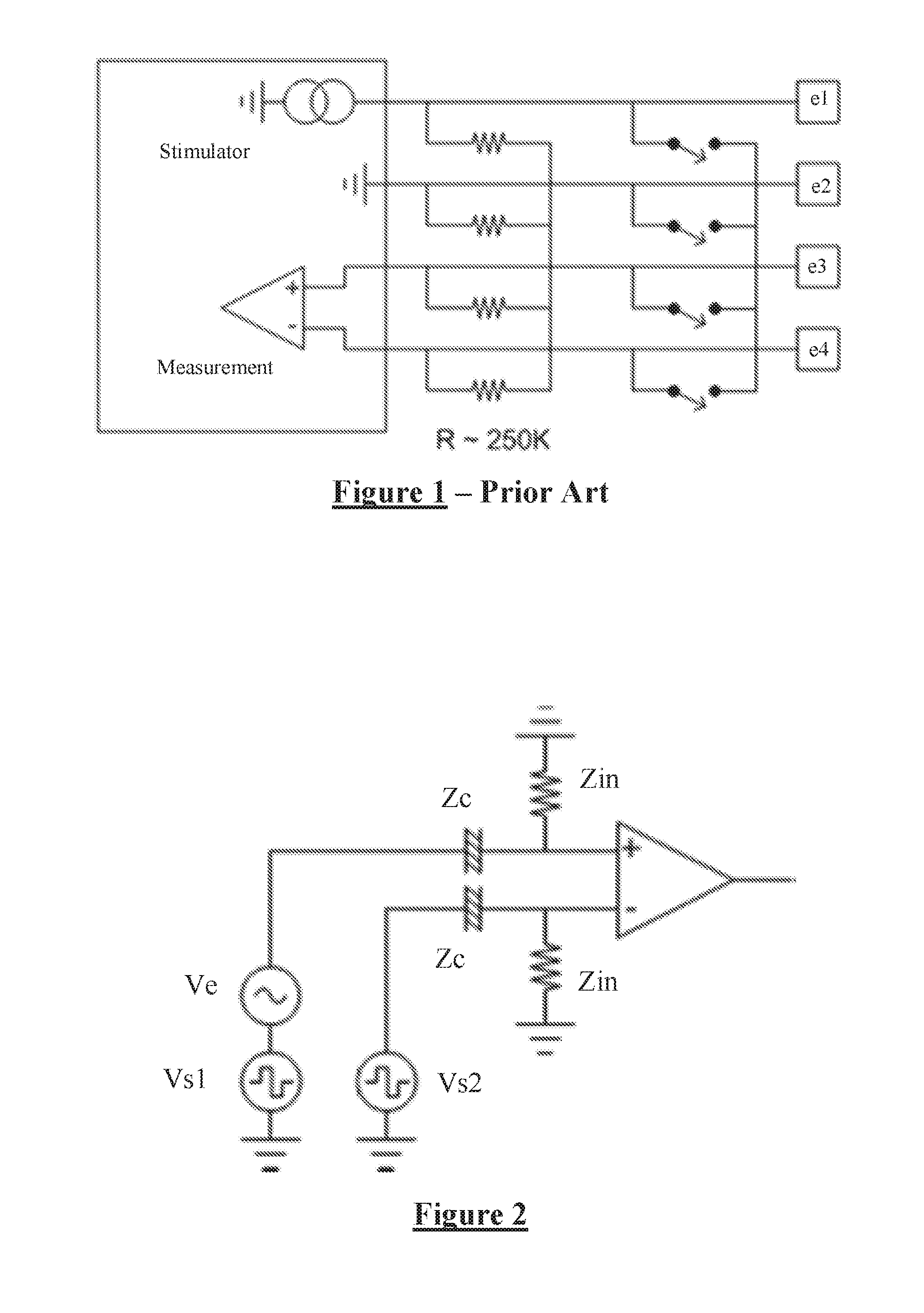
FIG. 1 illustrates a prior art approach to neural response measurement;
FIG. 2 illustrates a neural response measurement system in accordance with one embodiment of the present invention;
FIG. 3 illustrates an embodiment of the invention utilising electrode capacitors;
FIG. 4 is another illustration of the embodiment of FIG. 3, showing the stimulus electrode shorting arrangement;
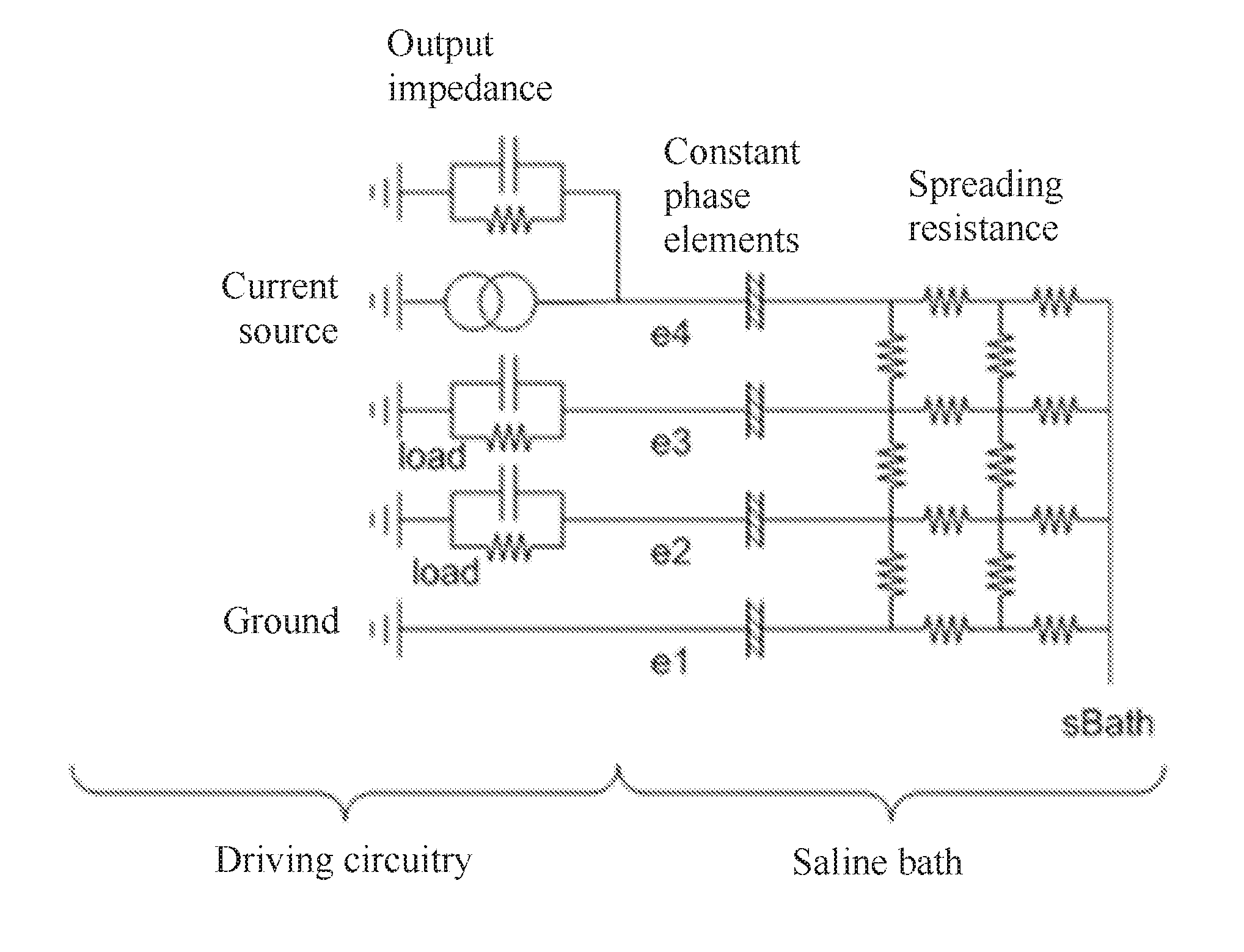
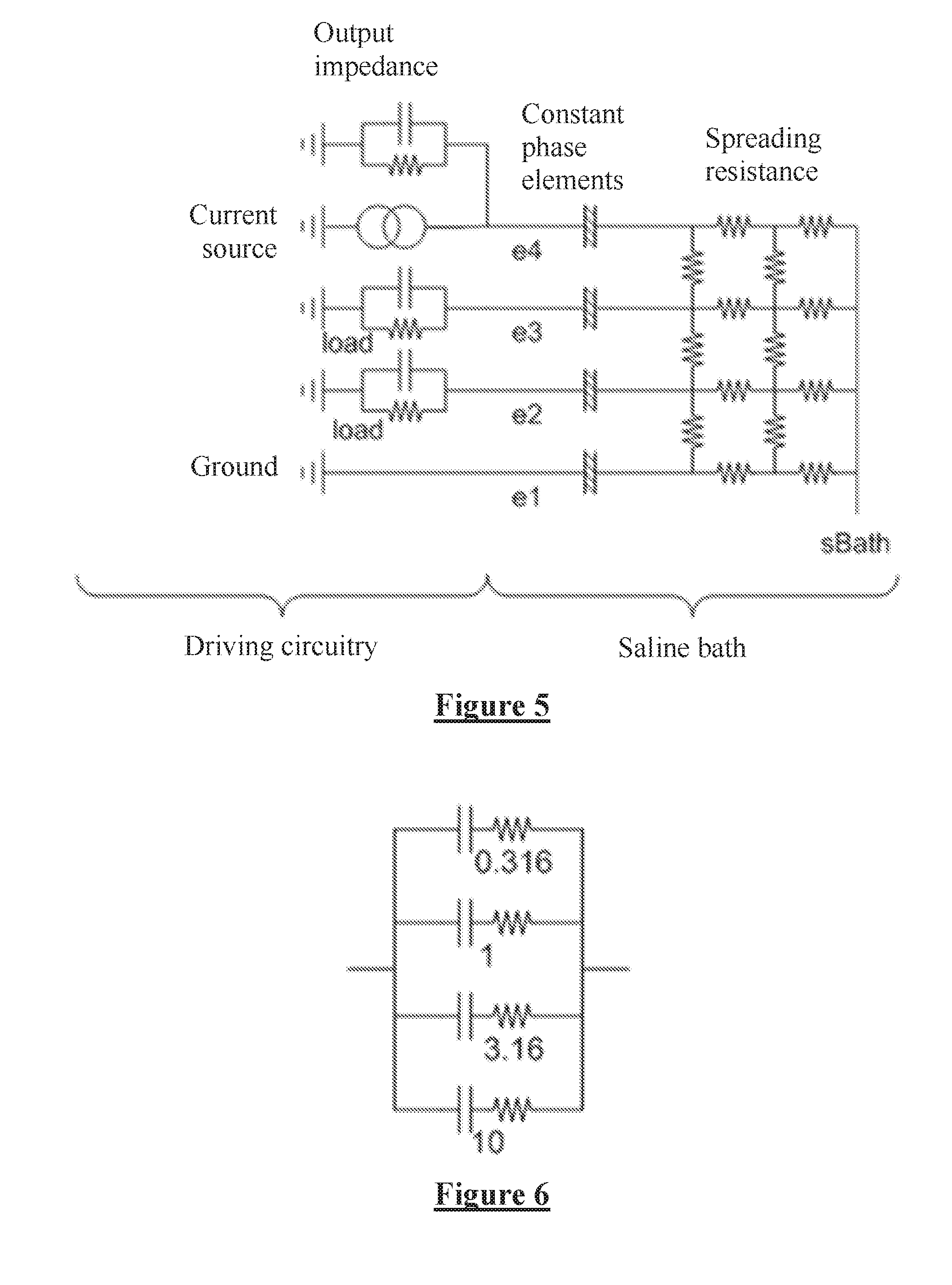
FIG. 5 is a simplified model of the driving circuitry of an implantable device and the surrounding tissue;
FIG. 6 is an illustrative equivalent circuit of the constant phase element at each electrode-tissue interface;
FIG. 7 is a plot produced by a simulation of the model of FIG. 5, showing the artifact arising after a stimulus in the presence of various values of amplifier input impedance, both capacitive and resistive;
FIG. 8 shows experimental data points, and simulation curves, of artefact arising from a stimulus when the amplifier input resistance and capacitance are varied;
FIG. 9 shows the RMS artifact contribution from resistance and capacitance respectively;
FIG. 10 shows artefact variation with resistance and capacitance; and
FIG. 11 shows RMS artefact variation with resistance and capacitance.
DESCRIPTION OF THE PREFERRED EMBODIMENTS
FIG. 2 illustrates a neural response measurement system in accordance with one embodiment of the present invention. Two sense electrodes each having a constant phase element (CPE) impedance of Z.sub.C are used to detect a neural response signal Ve arising in neural tissue of an implant recipient. A stimulus applied by stimulus electrodes of the implant (shown in FIG. 4) gives rise to the neural response, but also causes stimulus voltages V.sub.s1 and V.sub.s2 to be present on the sense electrodes. An input impedance of Z.sub.in is present at each input of the differential measurement amplifier.
The input impedance required in this embodiment of the invention is determined by noting that noise input is comparable to stimulation voltage, and that the goal is for the stimulus to induce a voltage (V.sub.s1-V.sub.s2) on the CPE of the sense electrodes which is less than the evoked response V.sub.E. Consequently the desired input impedance is given by:
>.times..times..times..times..times. ##EQU00003##
In one embodiment, being a spinal cord stimulator (SCS) having electrodes with an area of 14 mm.sup.2, Z.sub.c=20.OMEGA., (V.sub.s1-V.sub.s2).about.1V, V.sub.e=50 uV, so that the above equation dictates that the minimum value of Z.sub.in is 400 k.OMEGA.. To give a sufficient margin of V.sub.e over artefact, a more desirable value of Z.sub.in is larger, perhaps in the range 1-2 M.OMEGA.. In alternative embodiments such as a cochlear implant with electrode area of about 0.1 mm.sup.2, being a fraction of the area of an SCS electrode, the minimum required amplifier input impedance is many times higher; 8 M.OMEGA. or for sufficient margin more preferably 20 M.OMEGA., illustrating the difficulties of the resistance values chosen in FIG. 1.
FIG. 3 shows an embodiment of the present invention utilising an ASIC amplifier having a very high value of Zin. Electrode capacitors are provided to block DC insertion to the tissue, the electrode capacitors having a value of C.sub.in=5 pF. Since the ASIC amplifier of FIG. 3 automatically settles to zero during off periods there is no need for resistance to be added at the amplifier input.
FIG. 4 is another illustration of the embodiment of FIG. 2. Electrode capacitors are provided on all electrodes to block DC. The electrode capacitors can store their own charge which in turn can produce uncontrolled current on switch-on. Accordingly, the control module closes the switches to equilibrate the stimulus electrodes prior to each stimulus. The switches are closed only in short bursts so that the equilibration current does not rise to a level which is perceivable by the implant recipient. Similar embodiments may be provided having additional resistance and/or capacitance on the inputs of the measurement amplifier, so long as the input impedance obeys the equation above.
The importance of including the constant phase element model of the electrode-to-tissue interface in FIG. 2 for example arises from a simplified model of the driving circuitry and saline as shown in FIG. 5. The circuit consists of the spreading resistance, being a mesh of resistors that model the current through the bulk saline; the constant phase elements (CPE) where the saline meets the electrode metal; an excitation source having an output impedance including some stray capacitance; loading on each electrode and a ground connection. The saline bath has a bulk voltage point sBath. The saline bath is used to mimic tissue. In FIG. 5 a single-ended measurement can be made between electrodes e1 and e2, and a differential measurement can be made between e2 and e3.
An equivalent circuit of a CPE is shown in FIG. 6. It consists of a set of series RC networks connected in parallel. To adequately model a saline bath, the CPE might have 20-30 RC pairs, but the simplified version of FIG. 6 is shown for understanding. The RC pairs have time constants that change exponentially, in this case by a factor of sqrt(10), however the notable fact is that the time constants of each RC pair are different from all other RC pairs in the CPE. Following a stimulus, the output voltage of a CPE will change over time as charge redistributes between the capacitors, even though no net current is flowing in or out. This property is shared by a single parallel RC network, although a CPE has no R value that can be found at DC.
Unlike an RC network that shows a response characteristic of the circuit, the response of a CPE is dominated by the RC networks that have a similar time constant to that of the length of the stimulation. For example a SCS may have a stimulus pulse width in the range of 100-500 .mu.s. This result is important for defining the apparent conductance of a capacitor as discussed below.
Following a stimulus, there are three mechanisms or sources of artifact that can be identified in the circuit of FIG. 5. For each of these mechanisms, the load and current source impedances are considered infinite unless otherwise noted: The voltage on the CPE on electrode 1 changes. This can be seen in a single ended measurement e2-e1, or on the stimulating electrode e1. This is not seen in the differential measurement as this voltage is common mode between e2 and e3. If the current source output impedance is finite, the change in the electrode 1 CPE voltage causes a current to flow through the spreading resistance. This appears differentially on electrodes e2 and e3. This only occurs due to the mesh nature of the spreading resistance; if modelled by a star resistor or a single string of resistors this will not be observed. If the input impedance of either sense amplifier is finite, then during stimulus current will flow into this load. This will then settle.
The ability of the model of FIG. 5 to predict the voltage on e4 was experimentally tested. All stimulation used 4 mA 400 us biphasic pulses. These were used to give rise to an artifact large enough to resolve above noise, and with a voltage on the electrodes that could be digitized without anomaly. This stimulation level delivers 1.6 uC per stimulus, which is in the upper end of the range of charge required for comfort level stimulation in a SCS. Measurements were averaged over 99 iterations. As artefact can take many different profiles of either polarity, a single artefact measure was defined as being the integral of the Vt product of the signal, after resetting the DC value to a baseline.
In addition to experimental verification a simulation of FIG. 5 was conducted. FIG. 7 shows a simulation output showing the artifact over a selected range after the stimulus, in which the y-axis indicates RMS voltage.times.time, and the x-axis indicates admittance, with admittance of capacitances being calculated as Y=Ct, where t is the stimulus pulse width. Input impedance on the amplifier was selected to be either 330 pF, 1000 pF, 3300 pF, 330 k.OMEGA., and 100 k.OMEGA., giving rise to respective artefact waveforms 702, 704, 706, 708, 710. It is notable that capacitance and resistance give rise to artefact of opposite polarity. Although these are simple waveforms, in practice there can be several sources of artifact with different time-constants so that the actual artefact seen can be more complex than the simple monotic decreasing curves shown.
FIG. 8 shows both experimental data points and simulation curves, where the load resistance and capacitance are varied. The conductance of the capacitors, being their value divided by the length of each phase of the biphasic pulse, is a measure that has the same slope of artefact as for a resistor, and is thus preferred to using the entire length of the stimulus in FIGS. 8 to 11. The simulated line and the experimentally obtained data point groups having a positive slope in FIG. 8 show the effect of adding resistance, while the simulated line and the experimentally obtained data point groups having a negative slope show the effect of adding capacitance to the amplifier input impedance. The slopes of the capacitive and resistive lines are very similar for all electrodes, and closely match that of the simulation, indicating that the model of FIG. 5 is largely correct. The electrodes have different y-intercepts. Electrode 1 (the `r1.txt` data points) has a peak artifact of 700 uV when a resistive load is reduced, which is a very large artefact and would certainly obscure a neural response signal of around 10 uV. In the absence of loading, artifact can be positive or negative. The y-intercept offsets are outside the control of the electronics, and must be handled by techniques such as filtering.
While the plot of FIG. 8 validates the simulation model, it also shows that there is a missing element that causes artifact in the absence of loading and causes the y-intercept offsets. The y-intercept offsets vary from one electrode to the next, and is perhaps the result of metallic contamination on each electrode surface creating a small galvanic cell and asymmetric behaviour for the phases of the biphasic pulse.
FIG. 9 shows the RMS contribution to simulated artefact from resistance and capacitance respectively.
FIG. 10 shows artefact variation when both resistance and capacitance are progressively changed.
FIG. 11 shows artefact variation with resistance and capacitance using the above described RMS method.
In FIGS. 10 and 11, the curve dips then rises, consistent with FIG. 8. As expected, due to the DC offset, the RMS method obscures the fundamental accuracy of the model.
From the simulation model, using the above described baseline definition of artifact and a 400 us pulse width, the sensitivity of artefact to resistance is 4.1.times.10.sup.-2 Vs per mho, and the sensitivity of artefact to capacitance is -2.85.times.10.sup.-2 Vs per mho. Thus for a load of R, and where the artifact is over a 1 ms interval, then the voltage is V(r,t)=4.1.times.10.sup.-2/(R.times.t)
So for example, for an amplifier input resistance of 100 K.OMEGA. and a 1 ms artefact interval: V(100 k,1 ms)=400 uV
Further, for a capacitive load, and where the artifact is over a 1 ms interval, then the voltage is: V(C,t)=-7.14.times.10.sup.1.times.C/t
So for example for a 1000 pF load, artifact over 1 ms, artifact=71.4 uV.
Using this artefact calculation method, the following table shows the artifact contributions of various stray impedances which might be present in a typical SCS.
TABLE-US-00001 Artifact Contribution Stray Impedance Value for 1 ms in uV Cable 350p 25 input impedance 50k 820 Star load 270k 152 Output impedance of current source 135k 304 Reference inputs to amplifier 83.3K 492
As can be seen in the above table, appropriate adjustment and control of such impedances present in the neural measurement system can allow considerable sources of artefact to be reduced and ease the task measuring a neural signal of the order of 10 uV.
It will be appreciated by persons skilled in the art that numerous variations and/or modifications may be made to the invention as shown in the specific embodiments without departing from the spirit or scope of the invention as broadly described. The present embodiments are, therefore, to be considered in all respects as illustrative and not restrictive.
* * * * *
References
-
professional.medtronic.com:80/pt/neuro/scs/prod/restore-sensor/features-specifications/index.htm
-
battelle.org
-
en.wikipedia.org/wiki/Haptic_technology
-
-
smartech.gatech.edu/handle/1853/16192
-
psylab.com/html/default_bioamp.htm
-
umech.mit.edu/freeman/6.021J/2001/lab.pdf
-
practicalpainmanagement.com/pain/spine/radiculopathy/blocking-out-pain
D00000
D00001
D00002
D00003
D00004
D00005
D00006
M00001
M00002
M00003
XML
uspto.report is an independent third-party trademark research tool that is not affiliated, endorsed, or sponsored by the United States Patent and Trademark Office (USPTO) or any other governmental organization. The information provided by uspto.report is based on publicly available data at the time of writing and is intended for informational purposes only.
While we strive to provide accurate and up-to-date information, we do not guarantee the accuracy, completeness, reliability, or suitability of the information displayed on this site. The use of this site is at your own risk. Any reliance you place on such information is therefore strictly at your own risk.
All official trademark data, including owner information, should be verified by visiting the official USPTO website at www.uspto.gov. This site is not intended to replace professional legal advice and should not be used as a substitute for consulting with a legal professional who is knowledgeable about trademark law.