Tensioned sheathing aids
Crowley , et al. July 9, 2
U.S. patent number 10,342,660 [Application Number 15/413,642] was granted by the patent office on 2019-07-09 for tensioned sheathing aids. This patent grant is currently assigned to BOSTON SCIENTIFIC INC.. The grantee listed for this patent is BOSTON SCIENTIFIC SCIMED, INC.. Invention is credited to Andrew J. H. Backus, Brian D. Brandt, Luan Cao, Cornelius M. Crowley, Dwight J. Knab, Jr., Thu Pham, Ali Salahieh.


View All Diagrams
| United States Patent | 10,342,660 |
| Crowley , et al. | July 9, 2019 |
Tensioned sheathing aids
Abstract
A medical device apparatus may include a medical implant including an anchor member configured to actuate between a delivery configuration and a deployed configuration operatively connected to a delivery system, the delivery system including an outer sheath and an inner catheter disposed within the outer sheath, and a sheathing aid connecting the delivery system to the medical implant, the sheathing aid being configured to guide the medical implant into the outer sheath upon relative closing movement therebetween. The sheathing aid may include a plurality of tethers extending from the inner catheter to a proximal end of the anchor member, and a release mechanism slidably disposed within a coupler ring coupled to a distal end of the inner catheter. The plurality of tethers may be releasably coupled to the release mechanism.
| Inventors: | Crowley; Cornelius M. (San Francisco, CA), Salahieh; Ali (Saratoga, CA), Brandt; Brian D. (Morgan Hill, CA), Backus; Andrew J. H. (Santa Cruz, CA), Pham; Thu (San Jose, CA), Cao; Luan (Stockton, CA), Knab, Jr.; Dwight J. (Newark, CA) | ||||||||||
|---|---|---|---|---|---|---|---|---|---|---|---|
| Applicant: |
|
||||||||||
| Assignee: | BOSTON SCIENTIFIC INC. (Maple
Grove, MN) |
||||||||||
| Family ID: | 59385895 | ||||||||||
| Appl. No.: | 15/413,642 | ||||||||||
| Filed: | January 24, 2017 |
Prior Publication Data
| Document Identifier | Publication Date | |
|---|---|---|
| US 20170216029 A1 | Aug 3, 2017 | |
Related U.S. Patent Documents
| Application Number | Filing Date | Patent Number | Issue Date | ||
|---|---|---|---|---|---|
| 62289993 | Feb 2, 2016 | ||||
| Current U.S. Class: | 1/1 |
| Current CPC Class: | A61F 2/2436 (20130101); A61F 2/2439 (20130101); A61F 2/2418 (20130101); A61F 2002/9511 (20130101); A61F 2002/9534 (20130101); A61F 2002/9665 (20130101) |
| Current International Class: | A61F 2/24 (20060101); A61F 2/95 (20130101); A61F 2/966 (20130101) |
References Cited [Referenced By]
U.S. Patent Documents
| 15192 | June 1856 | Peale |
| 2682057 | June 1954 | Lord |
| 2701559 | February 1955 | Cooper |
| 2832078 | April 1958 | Williams |
| 3099016 | July 1963 | Edwards |
| 3113586 | December 1963 | Edmark, Jr. |
| 3130418 | April 1964 | Head et al. |
| 3143742 | August 1964 | Cromie |
| 3334629 | May 1967 | Cohn |
| 3367364 | February 1968 | Cruz, Jr. et al. |
| 3409013 | November 1968 | Berry |
| 3445916 | May 1969 | Schulte |
| 3540431 | November 1970 | Mobin-Uddin |
| 3548417 | December 1970 | Kischer et al. |
| 3570014 | March 1971 | Hancock |
| 3587115 | June 1971 | Shiley |
| 3592184 | July 1971 | Watkins et al. |
| 3628535 | December 1971 | Ostrowsky et al. |
| 3642004 | February 1972 | Osthagen et al. |
| 3657744 | April 1972 | Ersek |
| 3671979 | June 1972 | Moulopoulos |
| 3714671 | February 1973 | Edwards et al. |
| 3755823 | September 1973 | Hancock |
| 3795246 | March 1974 | Sturgeon |
| 3839741 | October 1974 | Haller |
| 3868956 | March 1975 | Alfidi et al. |
| 3874388 | April 1975 | King et al. |
| 3997923 | December 1976 | Possis |
| 4035849 | July 1977 | Angell et al. |
| 4056854 | November 1977 | Boretos et al. |
| 4106129 | August 1978 | Carpentier et al. |
| 4222126 | September 1980 | Boretos et al. |
| 4233690 | November 1980 | Akins |
| 4265694 | May 1981 | Boretos et al. |
| 4291420 | September 1981 | Reul |
| 4297749 | November 1981 | Davis et al. |
| 4323358 | April 1982 | Lentz et al. |
| 4326306 | April 1982 | Poler |
| 4339831 | July 1982 | Johnson |
| 4343048 | August 1982 | Ross et al. |
| 4345340 | August 1982 | Rosen |
| 4373216 | February 1983 | Klawitter |
| 4406022 | September 1983 | Roy |
| 4423809 | January 1984 | Mazzocco |
| 4425908 | January 1984 | Simon |
| 4470157 | September 1984 | Love |
| 4484579 | November 1984 | Meno et al. |
| 4501030 | February 1985 | Lane |
| 4531943 | July 1985 | Van Tassel et al. |
| 4535483 | August 1985 | Klawitter et al. |
| 4574803 | March 1986 | Storz |
| 4580568 | April 1986 | Gianturco |
| 4592340 | June 1986 | Boyles |
| 4602911 | July 1986 | Ahmadi et al. |
| 4605407 | August 1986 | Black et al. |
| 4610688 | September 1986 | Silvestrini et al. |
| 4612011 | September 1986 | Kautzky |
| 4617932 | October 1986 | Komberg |
| 4643732 | February 1987 | Pietsch et al. |
| 4647283 | March 1987 | Carpentier et al. |
| 4648881 | March 1987 | Carpentier et al. |
| 4655218 | April 1987 | Kulik et al. |
| 4655771 | April 1987 | Wallsten |
| 4662885 | May 1987 | Dipisa, Jr. |
| 4665906 | May 1987 | Jervis |
| 4680031 | July 1987 | Alonso |
| 4692164 | September 1987 | Dzemeshkevich et al. |
| 4705516 | November 1987 | Barone et al. |
| 4710192 | December 1987 | Liotta et al. |
| 4733665 | March 1988 | Palmaz |
| 4755181 | July 1988 | Igoe |
| 4759758 | July 1988 | Gabbay |
| 4777951 | October 1988 | Cribier et al. |
| 4787899 | November 1988 | Lazarus |
| 4787901 | November 1988 | Baykut |
| 4796629 | January 1989 | Grayzel |
| 4819751 | April 1989 | Shimada et al. |
| 4829990 | May 1989 | Thuroff et al. |
| 4834755 | May 1989 | Silvestrini et al. |
| 4851001 | July 1989 | Taheri |
| 4856516 | August 1989 | Hillstead |
| 4865600 | September 1989 | Carpentier et al. |
| 4872874 | October 1989 | Taheri |
| 4873978 | October 1989 | Ginsburg |
| 4878495 | November 1989 | Grayzel |
| 4878906 | November 1989 | Lindemann et al. |
| 4883458 | November 1989 | Shiber |
| 4885005 | December 1989 | Nashef et al. |
| 4909252 | March 1990 | Goldberger |
| 4917102 | April 1990 | Miller et al. |
| 4922905 | May 1990 | Strecker |
| 4927426 | May 1990 | Dretler |
| 4954126 | September 1990 | Wallsten |
| 4966604 | October 1990 | Reiss |
| 4969890 | November 1990 | Sugita et al. |
| 4979939 | December 1990 | Shiber |
| 4986830 | January 1991 | Owens et al. |
| 4994077 | February 1991 | Dobben |
| 5002556 | March 1991 | Ishida et al. |
| 5002559 | March 1991 | Tower |
| 5007896 | April 1991 | Shiber |
| 5026366 | June 1991 | Leckrone |
| 5032128 | July 1991 | Alonso |
| 5037434 | August 1991 | Lane |
| 5047041 | September 1991 | Samuels |
| 5064435 | November 1991 | Porter |
| 5080668 | January 1992 | Bolz et al. |
| 5085635 | February 1992 | Cragg |
| 5089015 | February 1992 | Ross |
| 5132473 | July 1992 | Furutaka et al. |
| 5141494 | August 1992 | Danforth et al. |
| 5152771 | October 1992 | Sabbaghian et al. |
| 5159937 | November 1992 | Tremulis |
| 5161547 | November 1992 | Tower |
| 5163953 | November 1992 | Vince |
| 5167628 | December 1992 | Boyles |
| 5209741 | May 1993 | Spaeth |
| 5215541 | June 1993 | Nashef et al. |
| 5217483 | June 1993 | Tower |
| 5238004 | August 1993 | Sahatjian et al. |
| 5258023 | November 1993 | Reger |
| 5258042 | November 1993 | Mehta |
| 5282847 | February 1994 | Trescony et al. |
| 5295958 | March 1994 | Shturman |
| 5332402 | July 1994 | Teitelbaum |
| 5336258 | August 1994 | Quintero et al. |
| 5350398 | September 1994 | Pavcnik et al. |
| 5360444 | November 1994 | Kusuhara |
| 5370685 | December 1994 | Stevens |
| 5387235 | February 1995 | Chuter |
| 5389106 | February 1995 | Tower |
| 5397351 | March 1995 | Pavcnik et al. |
| 5409019 | April 1995 | Wilk |
| 5411552 | May 1995 | Andersen et al. |
| 5425762 | June 1995 | Muller |
| 5431676 | July 1995 | Dubrul et al. |
| 5443446 | August 1995 | Shturman |
| 5443449 | August 1995 | Buelna |
| 5443477 | August 1995 | Mann et al. |
| 5443495 | August 1995 | Buscemi et al. |
| 5443499 | August 1995 | Schmitt |
| 5476506 | December 1995 | Lunn |
| 5476510 | December 1995 | Eberhardt et al. |
| 5480423 | January 1996 | Ravenscroft et al. |
| 5480424 | January 1996 | Cox |
| 5500014 | March 1996 | Quijano et al. |
| 5507767 | April 1996 | Maeda et al. |
| 5534007 | July 1996 | St. Germain et al. |
| 5545133 | August 1996 | Burns et al. |
| 5545209 | August 1996 | Roberts et al. |
| 5545211 | August 1996 | An et al. |
| 5545214 | August 1996 | Stevens |
| 5549665 | August 1996 | Vesely et al. |
| 5554185 | September 1996 | Block et al. |
| 5571175 | November 1996 | Vanney et al. |
| 5571215 | November 1996 | Sterman et al. |
| 5573520 | November 1996 | Schwartz et al. |
| 5575818 | November 1996 | Pinchuk |
| 5591185 | January 1997 | Kilmer et al. |
| 5591195 | January 1997 | Taheri et al. |
| 5607464 | March 1997 | Trescony et al. |
| 5609626 | March 1997 | Quijano et al. |
| 5645559 | July 1997 | Hachtman et al. |
| 5662671 | September 1997 | Barbut et al. |
| 5667523 | September 1997 | Bynon et al. |
| 5674277 | October 1997 | Freitag |
| 5693083 | December 1997 | Baker et al. |
| 5693310 | December 1997 | Gries et al. |
| 5695498 | December 1997 | Tower |
| 5709713 | January 1998 | Evans et al. |
| 5713951 | February 1998 | Garrison et al. |
| 5713953 | February 1998 | Vallana et al. |
| 5716370 | February 1998 | Williamson, IV et al. |
| 5716417 | February 1998 | Girard et al. |
| 5720391 | February 1998 | Dohm et al. |
| 5725549 | March 1998 | Lam |
| 5728068 | March 1998 | Leone et al. |
| 5733325 | March 1998 | Robinson et al. |
| 5735842 | April 1998 | Krueger et al. |
| 5749890 | May 1998 | Shaknovich |
| 5755783 | May 1998 | Stobie et al. |
| 5756476 | May 1998 | Epstein et al. |
| 5769812 | June 1998 | Stevens et al. |
| 5772609 | June 1998 | Nguyen et al. |
| 5800456 | September 1998 | Maeda et al. |
| 5800531 | September 1998 | Cosgrove et al. |
| 5807405 | September 1998 | Vanney et al. |
| 5817126 | October 1998 | Imran |
| 5824041 | October 1998 | Lenker et al. |
| 5824043 | October 1998 | Cottone, Jr. |
| 5824053 | October 1998 | Khosravi et al. |
| 5824055 | October 1998 | Spiridigliozzi et al. |
| 5824056 | October 1998 | Rosenberg |
| 5824064 | October 1998 | Taheri |
| 5840081 | November 1998 | Andersen et al. |
| 5843158 | December 1998 | Lenker et al. |
| 5855597 | January 1999 | Jayaraman |
| 5855601 | January 1999 | Bessler et al. |
| 5855602 | January 1999 | Angell |
| 5860966 | January 1999 | Tower |
| 5861024 | January 1999 | Rashidi |
| 5861028 | January 1999 | Angell |
| 5868783 | February 1999 | Tower |
| 5876419 | March 1999 | Carpenter et al. |
| 5876448 | March 1999 | Thompson et al. |
| 5885228 | March 1999 | Rosenman et al. |
| 5888201 | March 1999 | Stinson et al. |
| 5891191 | April 1999 | Stinson |
| 5895399 | April 1999 | Barbut et al. |
| 5906619 | May 1999 | Olson et al. |
| 5907893 | June 1999 | Ladno-Azizi et al. |
| 5910154 | June 1999 | Tsugita et al. |
| 5911734 | June 1999 | Tsugita et al. |
| 5925063 | July 1999 | Khosravi |
| 5944738 | August 1999 | Amplatz et al. |
| 5954766 | September 1999 | Ladno-Azizi et al. |
| 5957949 | September 1999 | Leonhardt et al. |
| 5968070 | October 1999 | Bley et al. |
| 5984957 | November 1999 | Laptewicz, Jr. et al. |
| 5984959 | November 1999 | Robertson et al. |
| 5993469 | November 1999 | McKenzie et al. |
| 5997557 | December 1999 | Barbut et al. |
| 6010522 | January 2000 | Barbut et al. |
| 6022370 | February 2000 | Tower |
| 6027520 | February 2000 | Tsugita et al. |
| 6027525 | February 2000 | Suh et al. |
| 6042598 | March 2000 | Tsugita et al. |
| 6042607 | March 2000 | Williamson, IV et al. |
| 6051014 | April 2000 | Jang |
| 6059827 | May 2000 | Fenton, Jr. |
| 6074418 | June 2000 | Buchanan et al. |
| 6093203 | July 2000 | Uflacker |
| 6096074 | August 2000 | Pedros |
| 6123723 | September 2000 | Konya et al. |
| 6132473 | October 2000 | Williams et al. |
| 6139510 | October 2000 | Palermo |
| 6142987 | November 2000 | Tsugita |
| 6146366 | November 2000 | Schachar |
| 6162245 | December 2000 | Jayaraman |
| 6165200 | December 2000 | Tsugita et al. |
| 6165209 | December 2000 | Patterson et al. |
| 6168579 | January 2001 | Tsugita |
| 6168614 | January 2001 | Andersen et al. |
| 6171327 | January 2001 | Daniel et al. |
| 6171335 | January 2001 | Wheatley et al. |
| 6179859 | January 2001 | Bates et al. |
| 6187016 | February 2001 | Hedges et al. |
| 6197053 | March 2001 | Cosgrove et al. |
| 6200336 | March 2001 | Pavcnik et al. |
| 6214036 | April 2001 | Letendre et al. |
| 6221006 | April 2001 | Dubrul et al. |
| 6221091 | April 2001 | Khosravi |
| 6221096 | April 2001 | Aiba et al. |
| 6221100 | April 2001 | Strecker |
| 6231544 | May 2001 | Tsuigita et al. |
| 6231551 | May 2001 | Barbut |
| 6241757 | June 2001 | An et al. |
| 6245102 | June 2001 | Jayaraman |
| 6251135 | June 2001 | Stinson et al. |
| 6258114 | July 2001 | Konya et al. |
| 6258115 | July 2001 | Dubrul |
| 6258120 | July 2001 | McKenzie et al. |
| 6258129 | July 2001 | Dybdal et al. |
| 6267783 | July 2001 | Letendre et al. |
| 6270513 | August 2001 | Tsugita et al. |
| 6277555 | August 2001 | Duran et al. |
| 6299637 | October 2001 | Shaolian et al. |
| 6302906 | October 2001 | Goicoechea et al. |
| 6309417 | October 2001 | Spence et al. |
| 6319281 | November 2001 | Patel |
| 6327772 | December 2001 | Zadno-Azizi et al. |
| 6336934 | January 2002 | Gilson et al. |
| 6336937 | January 2002 | Vonesh et al. |
| 6338735 | January 2002 | Stevens |
| 6346116 | February 2002 | Brooks et al. |
| 6348063 | February 2002 | Yassour et al. |
| 6352554 | March 2002 | De Paulis |
| 6352708 | March 2002 | Duran et al. |
| 6361545 | March 2002 | Macoviak et al. |
| 6363938 | April 2002 | Saadat et al. |
| 6364895 | April 2002 | Greenhalgh |
| 6371970 | April 2002 | Khosravi et al. |
| 6371983 | April 2002 | Lane |
| 6379383 | April 2002 | Palmaz et al. |
| 6398807 | June 2002 | Chouinard et al. |
| 6402736 | June 2002 | Brown et al. |
| 6409750 | June 2002 | Hyodoh et al. |
| 6416510 | July 2002 | Altman et al. |
| 6425916 | July 2002 | Garrison et al. |
| 6440164 | August 2002 | DiMatteo et al. |
| 6454799 | September 2002 | Schreck |
| 6458153 | October 2002 | Bailey et al. |
| 6461382 | October 2002 | Cao |
| 6468303 | October 2002 | Amplatz et al. |
| 6468660 | October 2002 | Ogle et al. |
| 6475239 | November 2002 | Campbell et al. |
| 6482228 | November 2002 | Norred |
| 6485501 | November 2002 | Green |
| 6485502 | November 2002 | Don Michael et al. |
| 6488704 | December 2002 | Connelly et al. |
| 6494909 | December 2002 | Greenhalgh |
| 6503272 | January 2003 | Duerig et al. |
| 6508803 | January 2003 | Horikawa et al. |
| 6508833 | January 2003 | Pavcnik et al. |
| 6527800 | March 2003 | McGuckin, Jr. et al. |
| 6530949 | March 2003 | Konya et al. |
| 6530952 | March 2003 | Vesely |
| 6537297 | March 2003 | Tsugita et al. |
| 6540768 | April 2003 | Diaz et al. |
| 6562058 | May 2003 | Seguin et al. |
| 6569196 | May 2003 | Vesely |
| 6572643 | June 2003 | Gharibadeh |
| 6585766 | July 2003 | Huynh et al. |
| 6592546 | July 2003 | Barbut et al. |
| 6592614 | July 2003 | Lenker et al. |
| 6605112 | August 2003 | Moll et al. |
| 6610077 | August 2003 | Hancock et al. |
| 6616682 | September 2003 | Joergensen et al. |
| 6622604 | September 2003 | Chouinard et al. |
| 6623518 | September 2003 | Thompson et al. |
| 6623521 | September 2003 | Steinke et al. |
| 6632243 | October 2003 | Zadno-Azizi et al. |
| 6635068 | October 2003 | Dubrul et al. |
| 6635079 | October 2003 | Unsworth et al. |
| 6652571 | November 2003 | White et al. |
| 6652578 | November 2003 | Bailey et al. |
| 6663588 | December 2003 | DuBois et al. |
| 6663663 | December 2003 | Kim et al. |
| 6669724 | December 2003 | Park et al. |
| 6673089 | January 2004 | Yassour et al. |
| 6673109 | January 2004 | Cox |
| 6676668 | January 2004 | Mercereau et al. |
| 6676692 | January 2004 | Rabkin et al. |
| 6676698 | January 2004 | McGuckin, Jr. et al. |
| 6682543 | January 2004 | Barbut et al. |
| 6682558 | January 2004 | Tu et al. |
| 6682559 | January 2004 | Myers et al. |
| 6685739 | February 2004 | DiMatteo et al. |
| 6689144 | February 2004 | Gerberding |
| 6689164 | February 2004 | Seguin |
| 6692512 | February 2004 | Jang |
| 6695864 | February 2004 | Macoviak et al. |
| 6695865 | February 2004 | Boyle et al. |
| 6702851 | March 2004 | Chinn et al. |
| 6712842 | March 2004 | Gifford, III et al. |
| 6712843 | March 2004 | Elliott |
| 6714842 | March 2004 | Ito |
| 6719789 | April 2004 | Cox |
| 6723116 | April 2004 | Taheri |
| 6730118 | May 2004 | Spenser et al. |
| 6730377 | May 2004 | Wang |
| 6733525 | May 2004 | Yang et al. |
| 6736846 | May 2004 | Cox |
| 6752828 | June 2004 | Thornton |
| 6755854 | June 2004 | Gillick et al. |
| 6758855 | July 2004 | Fulton, III et al. |
| 6764503 | July 2004 | Ishimaru |
| 6764509 | July 2004 | Chinn et al. |
| 6767345 | July 2004 | St. Germain et al. |
| 6769434 | August 2004 | Liddicoat et al. |
| 6773454 | August 2004 | Wholey et al. |
| 6776791 | August 2004 | Stallings et al. |
| 6786925 | September 2004 | Schoon et al. |
| 6790229 | September 2004 | Berreklouw |
| 6790230 | September 2004 | Beyersdorf et al. |
| 6790237 | September 2004 | Stinson |
| 6792979 | September 2004 | Konya et al. |
| 6797002 | September 2004 | Spence et al. |
| 6814746 | November 2004 | Thompson et al. |
| 6821297 | November 2004 | Snyders |
| 6830585 | December 2004 | Artof et al. |
| 6837901 | January 2005 | Rabkin et al. |
| 6840957 | January 2005 | DiMatteo et al. |
| 6843802 | January 2005 | Villalobos et al. |
| 6849085 | February 2005 | Marton |
| 6863668 | March 2005 | Gillespie et al. |
| 6866650 | March 2005 | Stevens et al. |
| 6866669 | March 2005 | Buzzard et al. |
| 6872223 | March 2005 | Roberts et al. |
| 6872226 | March 2005 | Cali et al. |
| 6875231 | April 2005 | Anduiza et al. |
| 6881220 | April 2005 | Edwin et al. |
| 6887266 | May 2005 | Williams et al. |
| 6890340 | May 2005 | Duane |
| 6893459 | May 2005 | Macoviak |
| 6893460 | May 2005 | Spenser et al. |
| 6905743 | June 2005 | Chen et al. |
| 6908481 | June 2005 | Cribier |
| 6911036 | June 2005 | Douk et al. |
| 6911043 | June 2005 | Myers et al. |
| 6936058 | August 2005 | Forde et al. |
| 6936067 | August 2005 | Buchanan |
| 6939352 | September 2005 | Buzzard et al. |
| 6951571 | October 2005 | Srivastava |
| 6953332 | October 2005 | Kurk et al. |
| 6964673 | November 2005 | Tsugita et al. |
| 6969395 | November 2005 | Eskuri |
| 6972025 | December 2005 | WasDyke |
| 6974464 | December 2005 | Quijano et al. |
| 6974474 | December 2005 | Pavcnik et al. |
| 6974476 | December 2005 | McGuckin, Jr. et al. |
| 6979350 | December 2005 | Moll et al. |
| 6984242 | January 2006 | Campbell et al. |
| 6989027 | January 2006 | Allen et al. |
| 7004176 | February 2006 | Lau |
| 7011681 | March 2006 | Vesely |
| 7018406 | March 2006 | Seguin et al. |
| 7025791 | April 2006 | Levine et al. |
| 7037331 | May 2006 | Mitelberg et al. |
| 7041132 | May 2006 | Quijano et al. |
| 7097658 | August 2006 | Oktay |
| 7122020 | October 2006 | Mogul |
| 7125418 | October 2006 | Duran et al. |
| 7141063 | November 2006 | White et al. |
| 7166097 | January 2007 | Barbut |
| 7175653 | February 2007 | Gaber |
| 7175654 | February 2007 | Bonsignore et al. |
| 7175656 | February 2007 | Khairkhahan |
| 7189258 | March 2007 | Johnson et al. |
| 7191018 | March 2007 | Gielen et al. |
| 7201772 | April 2007 | Schwammenthal et al. |
| 7235093 | June 2007 | Gregorich |
| 7258696 | August 2007 | Rabkin et al. |
| 7267686 | September 2007 | DiMatteo et al. |
| 7276078 | October 2007 | Spenser et al. |
| 7322932 | January 2008 | Xie et al. |
| 7326236 | February 2008 | Andreas et al. |
| 7329279 | February 2008 | Haug et al. |
| 7374560 | May 2008 | Ressemann et al. |
| 7381219 | June 2008 | Salahieh et al. |
| 7381220 | June 2008 | Macoviak et al. |
| 7399315 | July 2008 | Iobbi |
| 7445631 | November 2008 | Salahieh et al. |
| 7470285 | December 2008 | Nugent et al. |
| 7491232 | February 2009 | Bolduc et al. |
| 7510574 | March 2009 | L et al. |
| 7524330 | April 2009 | Berreklouw |
| 7530995 | May 2009 | Quijano et al. |
| 7544206 | June 2009 | Cohn |
| 7622276 | November 2009 | Cunanan et al. |
| 7628803 | December 2009 | Pavcnik et al. |
| 7632298 | December 2009 | Hijlkema et al. |
| 7674282 | March 2010 | Wu et al. |
| 7712606 | May 2010 | Salahieh et al. |
| 7722638 | May 2010 | Deyette, Jr. et al. |
| 7722662 | May 2010 | Steinke et al. |
| 7722666 | May 2010 | Lafontaine |
| 7736388 | June 2010 | Goldfarb et al. |
| 7748389 | July 2010 | Salahieh et al. |
| 7758625 | July 2010 | Wu et al. |
| 7780725 | August 2010 | Haug et al. |
| 7799065 | September 2010 | Pappas |
| 7803185 | September 2010 | Gabbay |
| 7824442 | November 2010 | Salahieh et al. |
| 7824443 | November 2010 | Salahieh et al. |
| 7833262 | November 2010 | McGuckin, Jr. et al. |
| 7846204 | December 2010 | Letac et al. |
| 7892292 | February 2011 | Stack et al. |
| 7918880 | April 2011 | Austin |
| 7938851 | May 2011 | Olson et al. |
| 7959666 | June 2011 | Salahieh et al. |
| 7959672 | June 2011 | Salahieh et al. |
| 7988724 | August 2011 | Salahieh et al. |
| 8048153 | November 2011 | Salahieh et al. |
| 8052749 | November 2011 | Salahieh et al. |
| 8136659 | March 2012 | Salahieh et al. |
| 8157853 | April 2012 | Laske et al. |
| 8182528 | May 2012 | Salahieh et al. |
| 8192351 | June 2012 | Fishler et al. |
| 8226710 | July 2012 | Nguyen et al. |
| 8231670 | July 2012 | Salahieh et al. |
| 8236049 | August 2012 | Rowe et al. |
| 8246678 | August 2012 | Salahieh et al. |
| 8252051 | August 2012 | Chau et al. |
| 8252052 | August 2012 | Salahieh et al. |
| 8287584 | October 2012 | Salahieh et al. |
| 8308798 | November 2012 | Pintor et al. |
| 8323335 | December 2012 | Rowe et al. |
| 8328868 | December 2012 | Paul et al. |
| 8343213 | January 2013 | Salahieh et al. |
| 8376865 | February 2013 | Forster et al. |
| 8377117 | February 2013 | Keidar et al. |
| 8398708 | March 2013 | Meiri et al. |
| 8579962 | November 2013 | Salahieh et al. |
| 8603160 | December 2013 | Salahieh et al. |
| 8617236 | December 2013 | Paul et al. |
| 8623074 | January 2014 | Ryan |
| 8623076 | January 2014 | Salahieh et al. |
| 8623078 | January 2014 | Salahieh et al. |
| 8668733 | March 2014 | Haug et al. |
| 8828078 | September 2014 | Salahieh et al. |
| 8840662 | September 2014 | Salahieh et al. |
| 8840663 | September 2014 | Salahieh et al. |
| 8858620 | October 2014 | Salahieh et al. |
| 2001/0002445 | May 2001 | Vesely |
| 2001/0007956 | July 2001 | Letac et al. |
| 2001/0010017 | July 2001 | Letac et al. |
| 2001/0021872 | September 2001 | Bailey et al. |
| 2001/0025196 | September 2001 | Chinn et al. |
| 2001/0032013 | October 2001 | Marton |
| 2001/0039450 | November 2001 | Pavcnik et al. |
| 2001/0041928 | November 2001 | Pavcnik et al. |
| 2001/0041930 | November 2001 | Globerman et al. |
| 2001/0044634 | November 2001 | Don Michael et al. |
| 2001/0044652 | November 2001 | Moore |
| 2001/0044656 | November 2001 | Williamson, IV et al. |
| 2002/0002396 | January 2002 | Fulkerson |
| 2002/0010489 | January 2002 | Grayzel et al. |
| 2002/0026233 | February 2002 | Shaknovich |
| 2002/0029014 | March 2002 | Jayaraman |
| 2002/0029981 | March 2002 | Nigam |
| 2002/0032480 | March 2002 | Spence et al. |
| 2002/0032481 | March 2002 | Gabbay |
| 2002/0042651 | April 2002 | Liddicoat et al. |
| 2002/0052651 | May 2002 | Myers et al. |
| 2002/0055767 | May 2002 | Forde et al. |
| 2002/0055769 | May 2002 | Wang |
| 2002/0058995 | May 2002 | Stevens |
| 2002/0077696 | June 2002 | Zadno-Azizi et al. |
| 2002/0082609 | June 2002 | Green |
| 2002/0095173 | July 2002 | Mazzocchi et al. |
| 2002/0095209 | July 2002 | Ladno-Azizi et al. |
| 2002/0111674 | August 2002 | Chouinard et al. |
| 2002/0120328 | August 2002 | Pathak et al. |
| 2002/0123802 | September 2002 | Snyders |
| 2002/0138138 | September 2002 | Yang |
| 2002/0151970 | October 2002 | Garrison et al. |
| 2002/0161390 | October 2002 | Mouw |
| 2002/0161392 | October 2002 | Dubrul |
| 2002/0161394 | October 2002 | Macoviak et al. |
| 2002/0165576 | November 2002 | Boyle et al. |
| 2002/0177766 | November 2002 | Mogul |
| 2002/0183781 | December 2002 | Casey et al. |
| 2002/0188341 | December 2002 | Elliott |
| 2002/0188344 | December 2002 | Bolea et al. |
| 2002/0193871 | December 2002 | Beyersdorf et al. |
| 2003/0014104 | January 2003 | Cribier |
| 2003/0023303 | January 2003 | Palmaz et al. |
| 2003/0028247 | February 2003 | Cali |
| 2003/0036791 | February 2003 | Philipp et al. |
| 2003/0040736 | February 2003 | Stevens et al. |
| 2003/0040771 | February 2003 | Hyodoh et al. |
| 2003/0040772 | February 2003 | Hyodoh et al. |
| 2003/0040791 | February 2003 | Oktay |
| 2003/0040792 | February 2003 | Gabbay |
| 2003/0050694 | March 2003 | Yang et al. |
| 2003/0055495 | March 2003 | Pease et al. |
| 2003/0057156 | March 2003 | Peterson et al. |
| 2003/0060844 | March 2003 | Borillo et al. |
| 2003/0069492 | April 2003 | Abrams et al. |
| 2003/0069646 | April 2003 | Stinson |
| 2003/0070944 | April 2003 | Nigam |
| 2003/0100918 | May 2003 | Duane |
| 2003/0100919 | May 2003 | Hopkins et al. |
| 2003/0109924 | June 2003 | Cribier |
| 2003/0109930 | June 2003 | Bluni et al. |
| 2003/0114912 | June 2003 | Sequin et al. |
| 2003/0114913 | June 2003 | Spenser et al. |
| 2003/0125795 | July 2003 | Pavcnik et al. |
| 2003/0130729 | July 2003 | Paniagua et al. |
| 2003/0135257 | July 2003 | Taheri |
| 2003/0144732 | July 2003 | Cosgrove et al. |
| 2003/0149475 | August 2003 | Hyodoh et al. |
| 2003/0149476 | August 2003 | Damm et al. |
| 2003/0149478 | August 2003 | Figulla et al. |
| 2003/0153974 | August 2003 | Spenser et al. |
| 2003/0171803 | September 2003 | Shimon |
| 2003/0176884 | September 2003 | Berrada et al. |
| 2003/0181850 | September 2003 | Diamond et al. |
| 2003/0187495 | October 2003 | Cully et al. |
| 2003/0191516 | October 2003 | Weldon et al. |
| 2003/0195609 | October 2003 | Berenstein et al. |
| 2003/0199759 | October 2003 | Richard |
| 2003/0199913 | October 2003 | Dubrul et al. |
| 2003/0199971 | October 2003 | Tower et al. |
| 2003/0199972 | October 2003 | Ladno-Azizi et al. |
| 2003/0208224 | November 2003 | Broome |
| 2003/0212429 | November 2003 | Keegan et al. |
| 2003/0212452 | November 2003 | Zadno-Azizi et al. |
| 2003/0212454 | November 2003 | Scott et al. |
| 2003/0216774 | November 2003 | Larson |
| 2003/0225445 | December 2003 | Derus et al. |
| 2003/0229390 | December 2003 | Ashton et al. |
| 2003/0233117 | December 2003 | Adams et al. |
| 2004/0019374 | January 2004 | Hojeibane et al. |
| 2004/0034411 | February 2004 | Quijano et al. |
| 2004/0039436 | February 2004 | Spenser et al. |
| 2004/0049224 | March 2004 | Buehlmann et al. |
| 2004/0049226 | March 2004 | Keegan et al. |
| 2004/0049262 | March 2004 | Obermiller et al. |
| 2004/0049266 | March 2004 | Anduiza et al. |
| 2004/0059409 | March 2004 | Stenzel |
| 2004/0073198 | April 2004 | Gilson et al. |
| 2004/0082904 | April 2004 | Houde et al. |
| 2004/0082967 | April 2004 | Broome et al. |
| 2004/0087982 | May 2004 | Eskuri |
| 2004/0088045 | May 2004 | Cox |
| 2004/0093016 | May 2004 | Root et al. |
| 2004/0093060 | May 2004 | Seguin et al. |
| 2004/0097788 | May 2004 | Mourlas et al. |
| 2004/0098022 | May 2004 | Barone |
| 2004/0098098 | May 2004 | McGuckin, Jr. et al. |
| 2004/0098099 | May 2004 | McCullagh et al. |
| 2004/0098112 | May 2004 | DiMatteo et al. |
| 2004/0107004 | June 2004 | Levine et al. |
| 2004/0111096 | June 2004 | Tu et al. |
| 2004/0116951 | June 2004 | Rosengart |
| 2004/0117004 | June 2004 | Osborne et al. |
| 2004/0117009 | June 2004 | Cali et al. |
| 2004/0122468 | June 2004 | Yodfat et al. |
| 2004/0122516 | June 2004 | Fogarty et al. |
| 2004/0127936 | July 2004 | Salahieh et al. |
| 2004/0127979 | July 2004 | Wilson et al. |
| 2004/0133274 | July 2004 | Webler et al. |
| 2004/0138694 | July 2004 | Tran et al. |
| 2004/0138742 | July 2004 | Myers et al. |
| 2004/0138743 | July 2004 | Myers et al. |
| 2004/0148018 | July 2004 | Carpentier et al. |
| 2004/0148021 | July 2004 | Cartledge et al. |
| 2004/0153094 | August 2004 | Dunfee et al. |
| 2004/0158277 | August 2004 | Lowe et al. |
| 2004/0167565 | August 2004 | Beulke et al. |
| 2004/0167620 | August 2004 | Ortiz et al. |
| 2004/0181140 | September 2004 | Falwell et al. |
| 2004/0186558 | September 2004 | Pavcnik et al. |
| 2004/0186563 | September 2004 | Lobbi |
| 2004/0193261 | September 2004 | Berreklouw |
| 2004/0199245 | October 2004 | Lauterjung |
| 2004/0204755 | October 2004 | Robin |
| 2004/0210304 | October 2004 | Seguin et al. |
| 2004/0210306 | October 2004 | Quijano et al. |
| 2004/0210307 | October 2004 | Khairkhahan |
| 2004/0215331 | October 2004 | Chew et al. |
| 2004/0215333 | October 2004 | Duran et al. |
| 2004/0215339 | October 2004 | Drasler et al. |
| 2004/0220655 | November 2004 | Swanson et al. |
| 2004/0225321 | November 2004 | Krolik et al. |
| 2004/0225353 | November 2004 | McGuckin, Jr. et al. |
| 2004/0225354 | November 2004 | Allen et al. |
| 2004/0225355 | November 2004 | Stevens |
| 2004/0243221 | December 2004 | Fawzi et al. |
| 2004/0254636 | December 2004 | Flagle et al. |
| 2004/0260390 | December 2004 | Sarac et al. |
| 2005/0010287 | January 2005 | Macoviak et al. |
| 2005/0021136 | January 2005 | Xie et al. |
| 2005/0033398 | February 2005 | Seguin |
| 2005/0033402 | February 2005 | Cully et al. |
| 2005/0043711 | February 2005 | Corcoran et al. |
| 2005/0043757 | February 2005 | Arad et al. |
| 2005/0043790 | February 2005 | Seguin |
| 2005/0049692 | March 2005 | Numamoto et al. |
| 2005/0049696 | March 2005 | Siess et al. |
| 2005/0055088 | March 2005 | Liddicoat et al. |
| 2005/0060016 | March 2005 | Wu et al. |
| 2005/0060029 | March 2005 | Le et al. |
| 2005/0065594 | March 2005 | DiMatteo et al. |
| 2005/0075584 | April 2005 | Cali |
| 2005/0075662 | April 2005 | Pedersen et al. |
| 2005/0075712 | April 2005 | Biancucci et al. |
| 2005/0075717 | April 2005 | Nguyen et al. |
| 2005/0075719 | April 2005 | Bergheim |
| 2005/0075724 | April 2005 | Svanidze et al. |
| 2005/0075730 | April 2005 | Myers et al. |
| 2005/0075731 | April 2005 | Artof et al. |
| 2005/0085841 | April 2005 | Eversull et al. |
| 2005/0085842 | April 2005 | Eversull et al. |
| 2005/0085843 | April 2005 | Opolski et al. |
| 2005/0085890 | April 2005 | Rasmussen et al. |
| 2005/0090846 | April 2005 | Pedersen et al. |
| 2005/0090890 | April 2005 | Wu et al. |
| 2005/0096692 | May 2005 | Linder et al. |
| 2005/0096734 | May 2005 | Majercak et al. |
| 2005/0096735 | May 2005 | Hojeibane et al. |
| 2005/0096736 | May 2005 | Osse et al. |
| 2005/0096738 | May 2005 | Cali et al. |
| 2005/0100580 | May 2005 | Osborne et al. |
| 2005/0107822 | May 2005 | Wasdyke |
| 2005/0113910 | May 2005 | Paniagua et al. |
| 2005/0131438 | June 2005 | Cohn |
| 2005/0137683 | June 2005 | Hezi-Yamit et al. |
| 2005/0137686 | June 2005 | Salahieh et al. |
| 2005/0137687 | June 2005 | Salahieh |
| 2005/0137688 | June 2005 | Salahieh et al. |
| 2005/0137689 | June 2005 | Salahieh et al. |
| 2005/0137690 | June 2005 | Salahieh et al. |
| 2005/0137691 | June 2005 | Salahieh et al. |
| 2005/0137692 | June 2005 | Haug et al. |
| 2005/0137693 | June 2005 | Haug et al. |
| 2005/0137694 | June 2005 | Haug et al. |
| 2005/0137695 | June 2005 | Salahieh et al. |
| 2005/0137696 | June 2005 | Salahieh et al. |
| 2005/0137697 | June 2005 | Salahieh et al. |
| 2005/0137698 | June 2005 | Salahieh et al. |
| 2005/0137699 | June 2005 | Salahieh et al. |
| 2005/0137701 | June 2005 | Salahieh et al. |
| 2005/0137702 | June 2005 | Haug et al. |
| 2005/0143807 | June 2005 | Pavcnik et al. |
| 2005/0143809 | June 2005 | Salahieh et al. |
| 2005/0149159 | July 2005 | Andreas et al. |
| 2005/0165352 | July 2005 | Henry et al. |
| 2005/0165477 | July 2005 | Anduiza et al. |
| 2005/0165479 | July 2005 | Drews et al. |
| 2005/0182486 | August 2005 | Gabbay |
| 2005/0197694 | September 2005 | Pai et al. |
| 2005/0197695 | September 2005 | Stacchino et al. |
| 2005/0203549 | September 2005 | Realyvasquez |
| 2005/0203614 | September 2005 | Forster et al. |
| 2005/0203615 | September 2005 | Forster et al. |
| 2005/0203616 | September 2005 | Cribier |
| 2005/0203617 | September 2005 | Forster et al. |
| 2005/0203618 | September 2005 | Sharkawy et al. |
| 2005/0209580 | September 2005 | Freyman |
| 2005/0228472 | October 2005 | Case et al. |
| 2005/0228495 | October 2005 | Macoviak |
| 2005/0234546 | October 2005 | Nugent et al. |
| 2005/0240200 | October 2005 | Bergheim |
| 2005/0240262 | October 2005 | White |
| 2005/0251250 | November 2005 | Verhoeven et al. |
| 2005/0251251 | November 2005 | Cribier |
| 2005/0261759 | November 2005 | Lambrecht et al. |
| 2005/0267560 | December 2005 | Bates |
| 2005/0283231 | December 2005 | Haug et al. |
| 2005/0283962 | December 2005 | Boudjemline |
| 2006/0004439 | January 2006 | Spenser et al. |
| 2006/0004442 | January 2006 | Spenser et al. |
| 2006/0015168 | January 2006 | Gunderson |
| 2006/0058872 | March 2006 | Salahieh et al. |
| 2006/0149360 | July 2006 | Schwammenthal et al. |
| 2006/0155312 | July 2006 | Levine et al. |
| 2006/0161249 | July 2006 | Realyvasquez et al. |
| 2006/0173524 | August 2006 | Salahieh et al. |
| 2006/0195183 | August 2006 | Navia et al. |
| 2006/0253191 | November 2006 | Salahieh et al. |
| 2006/0259134 | November 2006 | Schwammenthal et al. |
| 2006/0271166 | November 2006 | Thill et al. |
| 2006/0287668 | December 2006 | Fawzi et al. |
| 2006/0287717 | December 2006 | Rowe et al. |
| 2007/0010876 | January 2007 | Salahieh et al. |
| 2007/0010877 | January 2007 | Salahieh et al. |
| 2007/0016286 | January 2007 | Herrmann et al. |
| 2007/0055340 | March 2007 | Pryor |
| 2007/0061008 | March 2007 | Salahieh et al. |
| 2007/0088431 | April 2007 | Bourang |
| 2007/0112355 | May 2007 | Salahieh et al. |
| 2007/0118214 | May 2007 | Salahieh et al. |
| 2007/0162107 | July 2007 | Haug et al. |
| 2007/0173918 | July 2007 | Dreher et al. |
| 2007/0203503 | August 2007 | Salahieh et al. |
| 2007/0244552 | October 2007 | Salahieh et al. |
| 2007/0288089 | December 2007 | Gurskis et al. |
| 2008/0009940 | January 2008 | Cribier |
| 2008/0033541 | February 2008 | Gelbart et al. |
| 2008/0082165 | April 2008 | Wilson et al. |
| 2008/0125859 | May 2008 | Salahieh et al. |
| 2008/0188928 | August 2008 | Salahieh et al. |
| 2008/0208328 | August 2008 | Antocci et al. |
| 2008/0208332 | August 2008 | Lamphere et al. |
| 2008/0221672 | September 2008 | Lamphere et al. |
| 2008/0234814 | September 2008 | Salahieh et al. |
| 2008/0255661 | October 2008 | Straubinger et al. |
| 2008/0269878 | October 2008 | Iobbi |
| 2008/0288054 | November 2008 | Pulnev et al. |
| 2009/0005863 | January 2009 | Goetz et al. |
| 2009/0030512 | January 2009 | Thielen et al. |
| 2009/0054969 | February 2009 | Salahieh et al. |
| 2009/0076598 | March 2009 | Salahieh et al. |
| 2009/0093877 | April 2009 | Keidar et al. |
| 2009/0099640 | April 2009 | Weng |
| 2009/0171456 | July 2009 | Kveen et al. |
| 2009/0222076 | September 2009 | Figulla et al. |
| 2009/0264759 | October 2009 | Byrd |
| 2009/0264997 | October 2009 | Salahieh et al. |
| 2009/0299462 | December 2009 | Fawzi et al. |
| 2010/0049313 | February 2010 | Alon et al. |
| 2010/0094399 | April 2010 | Dorn et al. |
| 2010/0121434 | May 2010 | Paul et al. |
| 2010/0191326 | July 2010 | Alkhatib |
| 2010/0219092 | September 2010 | Salahieh et al. |
| 2010/0280495 | November 2010 | Paul et al. |
| 2011/0257735 | October 2011 | Salahieh et al. |
| 2011/0276129 | November 2011 | Salahieh et al. |
| 2012/0016469 | January 2012 | Salahieh et al. |
| 2012/0016471 | January 2012 | Salahieh et al. |
| 2012/0022642 | January 2012 | Haug et al. |
| 2012/0029627 | February 2012 | Salahieh et al. |
| 2012/0041549 | February 2012 | Salahieh et al. |
| 2012/0041550 | February 2012 | Salahieh et al. |
| 2012/0046740 | February 2012 | Paul et al. |
| 2012/0053683 | March 2012 | Salahieh et al. |
| 2012/0089224 | April 2012 | Haug et al. |
| 2012/0132547 | May 2012 | Salahieh et al. |
| 2012/0197379 | August 2012 | Laske et al. |
| 2012/0330409 | December 2012 | Haug et al. |
| 2013/0013057 | January 2013 | Salahieh et al. |
| 2013/0018457 | January 2013 | Gregg et al. |
| 2013/0030520 | January 2013 | Lee et al. |
| 2013/0123796 | May 2013 | Sutton et al. |
| 2013/0158656 | June 2013 | Sutton et al. |
| 2013/0190865 | July 2013 | Anderson |
| 2013/0197629 | August 2013 | Gainor |
| 2013/0304199 | November 2013 | Sutton et al. |
| 2014/0018911 | January 2014 | Zhou et al. |
| 2014/0094904 | April 2014 | Salahieh et al. |
| 2014/0114405 | April 2014 | Paul et al. |
| 2014/0114406 | April 2014 | Salahieh et al. |
| 2014/0121766 | May 2014 | Salahieh et al. |
| 2014/0135912 | May 2014 | Salahieh et al. |
| 2014/0243967 | August 2014 | Salahieh et al. |
| 2014/0296962 | October 2014 | Cartledge et al. |
| 2015/0127094 | May 2015 | Salahieh et al. |
| 1338951 | Mar 2002 | CN | |||
| 19532846 | Mar 1997 | DE | |||
| 19546692 | Jun 1997 | DE | |||
| 19857887 | Jul 2000 | DE | |||
| 19907646 | Aug 2000 | DE | |||
| 10049812 | Apr 2002 | DE | |||
| 10049813 | Apr 2002 | DE | |||
| 10049814 | Apr 2002 | DE | |||
| 10049815 | Apr 2002 | DE | |||
| 0103546 | May 1988 | EP | |||
| 0144167 | Nov 1989 | EP | |||
| 0409929 | Apr 1997 | EP | |||
| 0850607 | Jul 1998 | EP | |||
| 0597967 | Dec 1999 | EP | |||
| 1000590 | May 2000 | EP | |||
| 1057459 | Dec 2000 | EP | |||
| 1057460 | Dec 2000 | EP | |||
| 1088529 | Apr 2001 | EP | |||
| 0937439 | Sep 2003 | EP | |||
| 1340473 | Sep 2003 | EP | |||
| 1356793 | Oct 2003 | EP | |||
| 1042045 | May 2004 | EP | |||
| 0819013 | Jun 2004 | EP | |||
| 1430853 | Jun 2004 | EP | |||
| 1472996 | Nov 2004 | EP | |||
| 1229864 | Apr 2005 | EP | |||
| 1059894 | Jul 2005 | EP | |||
| 1078610 | Aug 2005 | EP | |||
| 1570809 | Sep 2005 | EP | |||
| 1576937 | Sep 2005 | EP | |||
| 1582178 | Oct 2005 | EP | |||
| 1582179 | Oct 2005 | EP | |||
| 1469797 | Nov 2005 | EP | |||
| 1600121 | Nov 2005 | EP | |||
| 1156757 | Dec 2005 | EP | |||
| 1616531 | Jan 2006 | EP | |||
| 1605871 | Jul 2008 | EP | |||
| 2788217 | Jul 2000 | FR | |||
| 2056023 | Mar 1981 | GB | |||
| 2398245 | Aug 2004 | GB | |||
| 1271508 | Nov 1986 | SU | |||
| 1371700 | Feb 1988 | SU | |||
| 9117720 | Nov 1991 | WO | |||
| 9217118 | Oct 1992 | WO | |||
| 9301768 | Feb 1993 | WO | |||
| 9315693 | Aug 1993 | WO | |||
| 9504556 | Feb 1995 | WO | |||
| 9529640 | Nov 1995 | WO | |||
| 9614032 | May 1996 | WO | |||
| 9624306 | Aug 1996 | WO | |||
| 9640012 | Dec 1996 | WO | |||
| 9829057 | Jul 1998 | WO | |||
| 9836790 | Aug 1998 | WO | |||
| 9850103 | Nov 1998 | WO | |||
| 9857599 | Dec 1998 | WO | |||
| 9933414 | Jul 1999 | WO | |||
| 9940964 | Aug 1999 | WO | |||
| 9944542 | Sep 1999 | WO | |||
| 9947075 | Sep 1999 | WO | |||
| 0009059 | Feb 2000 | WO | |||
| 0041652 | Jul 2000 | WO | |||
| 0044308 | Aug 2000 | WO | |||
| 0044311 | Aug 2000 | WO | |||
| 0044313 | Aug 2000 | WO | |||
| 0045874 | Aug 2000 | WO | |||
| 0047139 | Aug 2000 | WO | |||
| 0049970 | Aug 2000 | WO | |||
| 0067661 | Nov 2000 | WO | |||
| 0105331 | Jan 2001 | WO | |||
| 0108596 | Feb 2001 | WO | |||
| 0110320 | Feb 2001 | WO | |||
| 0110343 | Feb 2001 | WO | |||
| 0135870 | May 2001 | WO | |||
| 0149213 | Jul 2001 | WO | |||
| 0154625 | Aug 2001 | WO | |||
| 0162189 | Aug 2001 | WO | |||
| 0164137 | Sep 2001 | WO | |||
| 0176510 | Oct 2001 | WO | |||
| 0197715 | Dec 2001 | WO | |||
| 0236048 | May 2002 | WO | |||
| 0241789 | May 2002 | WO | |||
| 0243620 | Jun 2002 | WO | |||
| 0247575 | Jun 2002 | WO | |||
| 02056955 | Jul 2002 | WO | |||
| 02100297 | Dec 2002 | WO | |||
| 03003943 | Jan 2003 | WO | |||
| 03003949 | Jan 2003 | WO | |||
| 03011195 | Feb 2003 | WO | |||
| 03028592 | Apr 2003 | WO | |||
| 03030776 | Apr 2003 | WO | |||
| 03037227 | May 2003 | WO | |||
| 03047648 | Jun 2003 | WO | |||
| 03015851 | Nov 2003 | WO | |||
| 03094793 | Nov 2003 | WO | |||
| 03094797 | Nov 2003 | WO | |||
| 2004006803 | Jan 2004 | WO | |||
| 2004006804 | Jan 2004 | WO | |||
| 2004014256 | Feb 2004 | WO | |||
| 2004019811 | Mar 2004 | WO | |||
| 2004019817 | Mar 2004 | WO | |||
| 2004021922 | Mar 2004 | WO | |||
| 2004023980 | Mar 2004 | WO | |||
| 2004026117 | Apr 2004 | WO | |||
| 2004041126 | May 2004 | WO | |||
| 2004043293 | May 2004 | WO | |||
| 2004047681 | Jun 2004 | WO | |||
| 2004058106 | Jul 2004 | WO | |||
| 2004066876 | Aug 2004 | WO | |||
| 2004082536 | Sep 2004 | WO | |||
| 2004089250 | Oct 2004 | WO | |||
| 2004089253 | Oct 2004 | WO | |||
| 2004093728 | Nov 2004 | WO | |||
| 2004105651 | Dec 2004 | WO | |||
| 2005002466 | Jan 2005 | WO | |||
| 2005004753 | Jan 2005 | WO | |||
| 2005009285 | Feb 2005 | WO | |||
| 2005011534 | Feb 2005 | WO | |||
| 2005011535 | Feb 2005 | WO | |||
| 2005023155 | Mar 2005 | WO | |||
| 2005027790 | Mar 2005 | WO | |||
| 2005046528 | May 2005 | WO | |||
| 2005046529 | May 2005 | WO | |||
| 2005048883 | Jun 2005 | WO | |||
| 2005062980 | Jul 2005 | WO | |||
| 2005065585 | Jul 2005 | WO | |||
| 2005084595 | Sep 2005 | WO | |||
| 2005087140 | Sep 2005 | WO | |||
| 2005096993 | Oct 2005 | WO | |||
| 2006005015 | Jan 2006 | WO | |||
| 2006009690 | Jan 2006 | WO | |||
| 2006027499 | Mar 2006 | WO | |||
| 2006037086 | Apr 2006 | WO | |||
| 2006138391 | Dec 2006 | WO | |||
| 2007033093 | Mar 2007 | WO | |||
| 2007035471 | Mar 2007 | WO | |||
| 2007044285 | Apr 2007 | WO | |||
| 2007053243 | Apr 2007 | WO | |||
| 2007058847 | May 2007 | WO | |||
| 2007092354 | Aug 2007 | WO | |||
| 2007097983 | Aug 2007 | WO | |||
| 2010042950 | Apr 2010 | WO | |||
| 2012116368 | Aug 2012 | WO | |||
| 2013009975 | Jan 2013 | WO | |||
| 2013028387 | Feb 2013 | WO | |||
| 2013096545 | Jun 2013 | WO | |||
| 2016126511 | Aug 2016 | WO | |||
Other References
|
Andersen et al., "Transluminal implantation of artificial heart valves. Description of a new expandable aortic valve and initial results with implantation by catheter technique in closed chest pigs." Euro. Heart J., 13:704-708, May 1992. cited by applicant . Atwood et al., "Insertion of Heart Valves by Catheterization." Project Supervised by Prof. S. Muftu of Northeastern University 2001-2002: 36-40, May 30, 2002. cited by applicant . Bodnar et al., "Replacement Cardiac Valves R Chapter 13: Extinct Cardiac Valve Prostheses." Pergamon Publishing Corporation. New York, 307-322, 1991. cited by applicant . Boudjemline et al., "Percutaneous Implantation of a Biological Valve in the Aorta to Treat Aortic Valve Insufficiency--A Sheep Study." Med Sci. Monit., vol. 8, No. 4: BR113-116, Apr. 12, 2002. cited by applicant . Boudjemline et al., "Percutaneous Implantation of a Valve in the Descending Aorta in Lambs." Euro. Heart J., 23: 1045-1049, Jul. 2002. cited by applicant . Boudjemline et al., "Percutaneous Pulmonary Valve Replacement in a Large Right Ventricular Outflow Tract: An Experimental Study." Journal of the American College of Cardiology, vol. 43(6): 1082-1087, Mar. 17, 2004. cited by applicant . Boudjemline et al., "Percutaneous Valve Insertion: A New Approach?" J. of Thoracic and Cardio. Surg, 125(3): 741-743, Mar. 2003. cited by applicant . Boudjemline et al., "Steps Toward Percutaneous Aortic Valve Replacement." Circulation, 105: 775-778, Feb. 12, 2002. cited by applicant . Cribier et al., "Early Experience with Percutaneous Transcatheter Implantation of Heart Valve Prosthesis for the Treatment of End-Stage Inoperable Patients with Calcific Aortic Stenosis." J. of Am. Coll. of Cardio, 43(4): 698-703, Feb. 18, 2004. cited by applicant . Cribier et al., "Percutaneous Transcatheter Implementation of an Aortic Valve Prosthesis for Calcitic Aortic Stenosis: First Human Case Description." Circulation, 106: 3006-3008, Dec. 10, 2002. cited by applicant . Cribier et al., "Percutaneous Transcatheter Implantation of an Aortic Valve Prosthesis for Calcific Aortic Stenosis: First Human Case." Percutaneous Valve Technologies, Inc., 16 pages, Apr. 16, 2002. cited by applicant . Ferrari et al., "Percutaneous Transvascular Aortic Valve Replacement with Self-Expanding Stent-Valve Device." Poster from the presentation given at SMIT 2000, 12th International Conference. Sep. 5, 2000. cited by applicant . Hijazi, "Transcatheter Valve Replacement: A New Era of Percutaneous Cardiac Intervention Begins." J. of Am. College of Cardio., 43(6): 1088-1089, Mar. 17, 2004. cited by applicant . Huber et al., "Do Valved Stents Compromise Coronary Flow?" European Journal of Cardio-thoracic Surgery, vol. 25: 754-759, Jan. 23, 2004. cited by applicant . Knudsen et al., "Catheter-implanted prosthetic heart valves." Int'l J. of Art. Organs, 16(5): 253-262, May 1993. cited by applicant . Kort et al., "Minimally Invasive Aortic Valve Replacement: Echocardiographic and Clinical Results." Am. Heart J., 142(3): 476-481, Sep. 2001. cited by applicant . Love et al., The Autogenous Tissue Heart Valve: Current Status. Journal of Cardiac Surgery, 6(4): 499-507, Mar. 1991. cited by applicant . Lutter et al., "Percutaneous Aortic Valve Replacement: An Experimental Study. I. Studies on Implantation." J. of Thoracic and Cardio. Surg., 123(4): 768-776, Apr. 2002. cited by applicant . Moulopoulos et al., "Catheter-Mounted Aortic Valves." Annals of Thoracic Surg., 11(5): 423-430, May 1971. cited by applicant . Paniagua et al., "Percutaneous Heart Valve in the Chronic in Vitro Testing Model." Circulation, 106: e51-e52, Sep. 17, 2002. cited by applicant . Paniagua et al., "Heart Watch." Texas Heart Institute. Edition: 8 pages, Spring, 2004. cited by applicant . Pavcnik et al., "Percutaneous Bioprosthetic Venous Valve: A Long-term Study in Sheep." J. of Vascular Surg., 35(3): 598-603, Mar. 2002. cited by applicant . Phillips et al., "A Temporary Catheter-Tip Aortic Valve: Hemodynamic Effects on Experimental Acute Aortic Insufficiency." Annals of Thoracic Surg., 21(2): 134-136, Feb. 1976. cited by applicant . Sochman et al., "Percutaneous Transcatheter Aortic Disc Valve Prosthesis Implantation: A Feasibility Study." Cardiovasc. Intervent. Radiol., 23: 384-388, Sep. 2000. cited by applicant . Stuart, "In Heart Valves, A Brave, New Non-Surgical World." Start-Up. Feb. 9-17, 2004. cited by applicant . Vahanian et al., "Percutaneous Approaches to Valvular Disease." Circulation, 109: 1572-1579, Apr. 6, 2004. cited by applicant . Van Herwerden et al., "Percutaneous Valve Implantation: Back to the Future?" Euro. Heart J., 23(18): 1415-1416, Sep. 2002. cited by applicant . Zhou et al, "Self-expandable Valved Stent of Large Size: Off-Bypass Implantation in Pulmonary Position." Eur. J. Cardiothorac, 24: 212-216, Aug. 2003. cited by applicant . Examiner's First Report on AU Patent Application No. 2011202667, dated May 17, 2012. cited by applicant . "A Matter of Size." Triennial Review of the National Nanotechnology Initiative, The National Academies Press, Washington DC, v-13, http://www.nap.edu/catalog/11752/a-matter-of-size-triennial-review-of-the- -national-nanotechnology, 2006. cited by applicant . Atwood et al., "Insertion of Heart Valves by Catheterization." The Capstone Design Course Report MIME 1501-1502. Technical Design Report Northeastern University, pp. 1-93, Nov. 5, 2007. cited by applicant . Supplemental Search Report from EP Patent Office, EP Application No. 04813777.2, dated Aug. 19, 2011. cited by applicant . Supplemental Search Report from EP Patent Office, EP Application No. 04815634.3, dated Aug. 19, 2011. cited by applicant . Cunanan et al., "Tissue Characterization and Calcification Potential of Commercial Bioprosthetic Heart Valves." Ann. Thorac. Surg., S417-421, May 15, 2001. cited by applicant . Cunliffe et al., "Glutaraldehyde Inactivation of Exotic Animal Viruses in Swine Heart Tissue." Applied and Environmental Microbiology, Greenport, New York, 37(5): 1044-1046, May 1979. cited by applicant . EP Search Report for EP Application No. 06824992.9, dated Aug. 10, 2011. cited by applicant . "Heart Valve Materials--Bovine (cow)." Equine & Porcine Pericardium, Maverick Biosciences Pty. Lt, http://maverickbio.com/biological-medical-device-materials.php?htm. 2009. cited by applicant . Helmus, "Mechanical and Bioprosthetic Heart Valves in Biomaterials for Artificial Organs." Woodhead Publishing Limited: 114-162, 2011. cited by applicant . Hourihan et al., "Transcatheter Umbrella Closure of Valvular and Paravalvular Leaks." JACC, Boston, Massachusetts, 20(6): 1371-1377, Nov. 15, 1992. cited by applicant . Laborde et al., "Percutaneous Implantation of the Corevalve Aortic Valve Prosthesis for Patients Presenting High Risk for Surgical Valve Replacement." EuroIntervention: 472-474, Feb. 2006. cited by applicant . Levy, "Mycobacterium chelonei Infection of Porcine Heart Valves." The New England Journal of Medicine, Washington DC, 297(12), Sep. 22, 1977. cited by applicant . Supplemental Search Report from EP Patent Office, EP Application No. 05758878.2, dated Oct. 24, 2011. cited by applicant . "Pericardial Heart Valves." Edwards Lifesciences, Cardiovascular Surgery FAQ, http://www.edwards.com/products/cardiovascularsurgeryfaq.htm, Nov. 14, 2010. cited by applicant . Southern Lights Biomaterials Homepage, http://www.slv.co.nz/, Jan. 7, 2011. cited by applicant . Stassano. "Mid-term Results of the Valve-on-Valve Technique for Bioprosthetic Failure." European Journal of Cardiothoracic Surgery: vol. 18, 453-457, Oct. 2000. cited by applicant . Topol. "Percutaneous Expandable Prosthetic Valves." Textbook of Interventional Cardiology, W.B. Saunders Company, 2: 1268-1276, 1994. cited by applicant . International Search Report and Written Opinion dated Apr. 11, 2017 for International Application No. PCT/US2017/015629. cited by applicant. |
Primary Examiner: Holwerda; Kathleen S
Attorney, Agent or Firm: Seager, Tufte & Wickhem LLP
Parent Case Text
RELATED APPLICATIONS
This application claims the benefit of U.S. Provisional Application Ser. No. 62/289,993, filed Feb. 2, 2016.
Claims
What is claimed is:
1. A medical device apparatus, comprising: a medical implant including a braided anchor member operatively connected to a delivery system, the delivery system including a handle, an outer sheath extending distally from the handle, and an inner catheter disposed within the outer sheath; and a sheathing aid connecting the delivery system to the medical implant, the sheathing aid being configured to guide the medical implant into the outer sheath upon compression of the sheathing aid as the sheathing aid is withdrawn into the outer sheath; wherein the sheathing aid includes a plurality of filaments extending from the inner catheter to a proximal end of the braided anchor member, and a cleat disc disposed within a coupler ring fixedly attached to a distal end of the inner catheter; wherein the plurality of filaments is releasably coupled to the cleat disc, wherein the delivery system includes at least one actuator element extending from the inner catheter to the medical implant, the at least one actuator element being configured to reversibly shift the braided anchor member from an elongated delivery configuration to an enlarged deployed configuration, wherein each of the at least one actuator element passes through the cleat disc.
2. The medical device apparatus of claim 1, wherein the cleat disc is movably disposed within the coupler ring.
3. The medical device apparatus of claim 1, wherein the cleat disc includes one or more cleat posts extending distally from the cleat disc.
4. The medical device apparatus of claim 3, wherein the plurality of filaments is releasably coupled to the one or more cleat posts.
5. The medical device apparatus of claim 3, wherein the one or more cleat posts comprises three cleat posts.
6. The medical device apparatus of claim 1, wherein the inner catheter includes a plurality of fingers extending distally from the coupler ring, the plurality of fingers being releasably coupled to the medical implant.
7. The medical device apparatus of claim 6, wherein the plurality of filaments extend through one or more openings disposed within a side wall of the coupler ring.
8. The medical device apparatus of claim 1, wherein at least some of the plurality of filaments each include a tubular member disposed thereon between the inner catheter and the medical implant.
9. The medical device apparatus of claim 8, wherein the at least some of the plurality of filaments comprises all of the plurality of filaments.
10. The medical device apparatus of claim 8, wherein each tubular member has a length, the length of all of the tubular members being substantially similar.
11. The medical device apparatus of claim 8, wherein the tubular members have varying lengths.
12. The medical device apparatus of claim 1, wherein each of the at least one actuator element includes a tubular sleeve disposed thereon and extending between the cleat disc and the medical implant.
13. The medical device apparatus of claim 1, wherein each of the at least one actuator element includes an enlarged portion disposed between the cleat disc and the medical implant.
14. The medical device apparatus of claim 1, wherein proximal translation of the at least one actuator element moves the cleat disc proximally after the braided anchor member has been shifted to the enlarged deployed configuration.
15. The medical device apparatus of claim 14, wherein moving the cleat disc proximally releases the plurality of filaments from the cleat disc.
16. The medical device apparatus of claim 1, wherein the braided anchor member includes a plurality of crowns, wherein each of the plurality of filaments is releasably attached at one of the plurality of crowns.
Description
TECHNICAL FIELD
The present disclosure pertains to medical devices, and methods for manufacturing and/or using medical devices. More particularly, the present disclosure pertains to sheathing aids for a medical device and/or a replacement heart valve.
BACKGROUND
A wide variety of intracorporeal medical devices have been developed for medical use, for example, intravascular use. Some of these devices include guidewires, catheters, medical device delivery systems (e.g., for stents, grafts, replacement valves, etc.), and the like. These devices are manufactured by any one of a variety of different manufacturing methods and may be used according to any one of a variety of methods. Of the known medical devices and methods, each has certain advantages and disadvantages. There is an ongoing need to provide alternative medical devices as well as alternative methods for manufacturing and using medical devices.
SUMMARY
In a first aspect, a medical device apparatus may comprise a medical implant including a braided anchor member operatively connected to a delivery system, the delivery system including a handle, an outer sheath extending distally from the handle, and an inner catheter disposed within the outer sheath, and a sheathing aid connecting the delivery system to the medical implant, the sheathing aid being configured to guide the medical implant into the outer sheath upon relative closing movement therebetween. The sheathing aid may include a plurality of filaments extending from the inner catheter to a proximal end of the braided anchor member, and a cleat disc disposed within a coupler ring fixedly attached to a distal end of the inner catheter. The plurality of filaments may be releasably coupled to the cleat disc.
In addition or alternatively, and in a second aspect, the cleat disc is movably disposed within the coupler ring.
In addition or alternatively, and in a third aspect, the cleat disc includes one or more cleat posts extending distally from the cleat disc.
In addition or alternatively, and in a fourth aspect, the plurality of filaments is releasably coupled to the one or more cleat posts.
In addition or alternatively, and in a fifth aspect, the one or more cleat posts comprises three cleat posts.
In addition or alternatively, and in a sixth aspect, the inner catheter includes a plurality of fingers extending distally from the coupler ring, the plurality of fingers being releasably coupled to the medical implant.
In addition or alternatively, and in a seventh aspect, the plurality of filaments extend through one or more openings disposed within a side wall of the coupler ring.
In addition or alternatively, and in an eighth aspect, at least some of the plurality of filaments each include a tubular member disposed thereon between the inner catheter and the medical implant.
In addition or alternatively, and in a ninth aspect, the at least some of the plurality of filaments comprises all of the plurality of filaments.
In addition or alternatively, and in a tenth aspect, each tubular member has a length, the length of all of the tubular members being substantially similar.
In addition or alternatively, and in an eleventh aspect, the tubular members have varying lengths.
In addition or alternatively, and in a twelfth aspect, the delivery system includes at least one actuator element extending from the inner catheter to the medical implant, the at least one actuator element being configured to reversibly shift the braided anchor member from an elongated delivery configuration to an enlarged deployed configuration.
In addition or alternatively, and in a thirteenth aspect, each of the at least one actuator element passes through the cleat disc.
In addition or alternatively, and in a fourteenth aspect, each of the at least one actuator element includes a tubular sleeve disposed thereon and extending between the cleat disc and the medical implant.
In addition or alternatively, and in a fifteenth aspect, each of the at least one actuator element includes an enlarged portion disposed between the cleat disc and the medical implant.
In addition or alternatively, and in a sixteenth aspect, proximal translation of the at least one actuator element moves the cleat disc proximally after the braided anchor member has been shifted to the enlarged deployed configuration.
In addition or alternatively, and in a seventeenth aspect, moving the cleat disc proximally releases the plurality of filaments from the cleat disc.
In addition or alternatively, and in an eighteenth aspect, the braided anchor member includes a plurality of crowns, wherein each of the plurality of filaments is releasably attached at one of the plurality of crowns.
In addition or alternatively, and in a nineteenth aspect, a medical device apparatus may comprise a medical implant including an anchor member configured to actuate between a delivery configuration and a deployed configuration operatively connected to a delivery system, the delivery system including a handle, an outer sheath extending distally from the handle, and an inner catheter disposed within the outer sheath, and a sheathing aid connecting the delivery system to the medical implant, the sheathing aid being configured to guide the medical implant into the outer sheath upon relative closing movement therebetween. The sheathing aid may include a plurality of tethers extending from the inner catheter to a proximal end of the anchor member, and a release mechanism slidably disposed within a coupler ring coupled to a distal end of the inner catheter. The plurality of tethers may be releasably coupled to the release mechanism.
In addition or alternatively, and in a twentieth aspect, a medical device apparatus may comprise a medical implant including a tubular anchoring structure configured to shift between an elongated configuration and an expanded configuration operatively connected to a delivery system, the delivery system including a handle, an outer sheath extending distally from the handle, and an inner catheter disposed within the outer sheath, and a sheathing aid connecting the delivery system to the medical implant, the sheathing aid being configured to guide the medical implant into the outer sheath upon relative closing movement therebetween. The sheathing aid may include a plurality of tensioning elements extending from the inner catheter to a proximal end of the tubular anchoring structure, and a release pin disposed within a coupler ring attached to a distal end of the inner catheter. The plurality of tensioning elements may be releasably coupled to the release pin.
The above summary of some embodiments, aspects, and/or examples is not intended to describe each disclosed embodiment or every implementation of the present disclosure. The Figures, and Detailed Description, which follow, more particularly exemplify these embodiments.
BRIEF DESCRIPTION OF THE DRAWINGS
The disclosure may be more completely understood in consideration of the following detailed description in connection with the accompanying drawings, in which:
FIG. 1 illustrates an example medical device system;
FIG. 2 illustrates a portion of the example medical device system of FIG. 1;
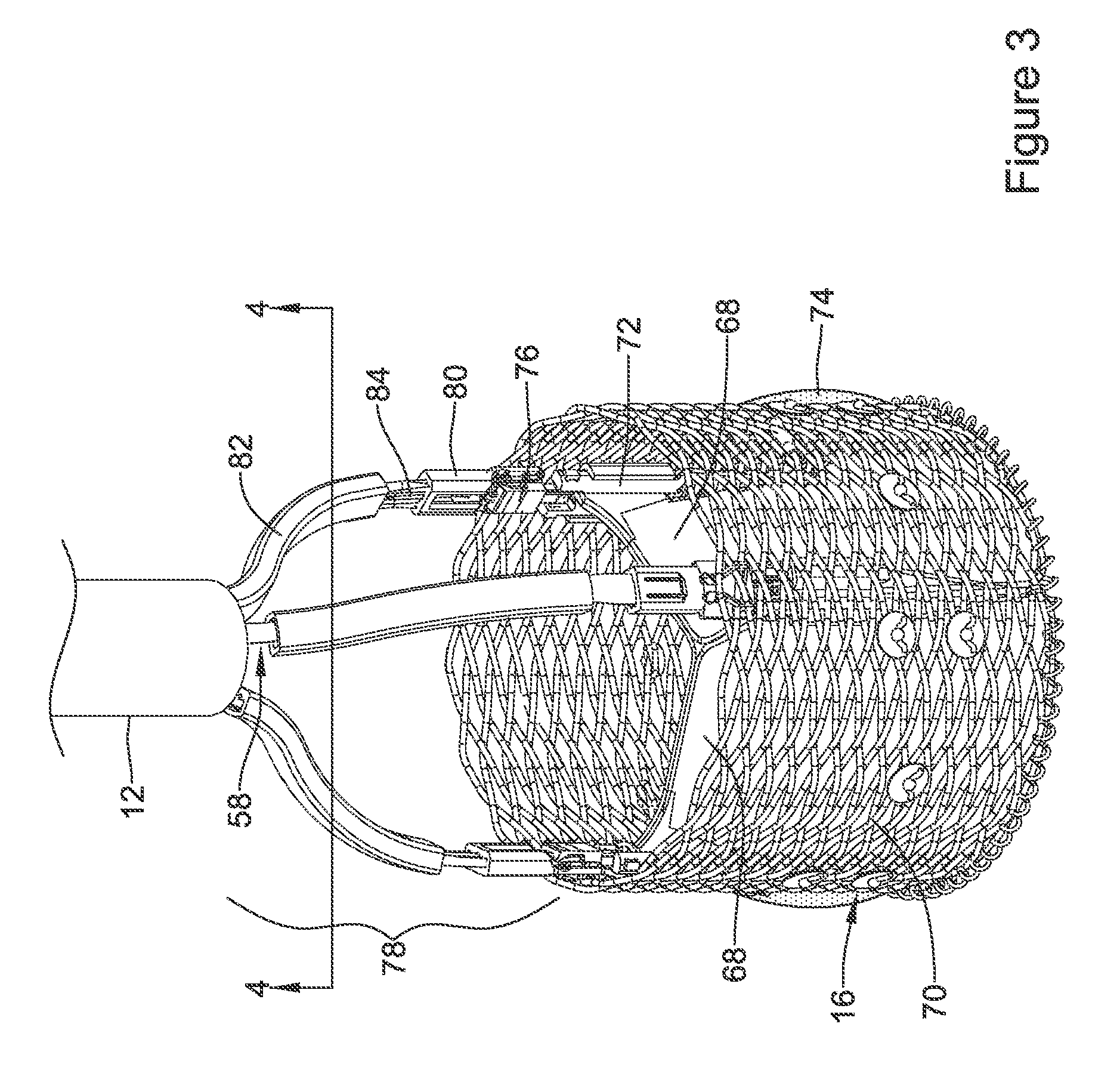
FIG. 3 illustrates an example medical implant associated with an example medical device system;
FIG. 4 illustrates a modified end view of a portion of an example medical device system taken along line 4-4 in FIG. 3;
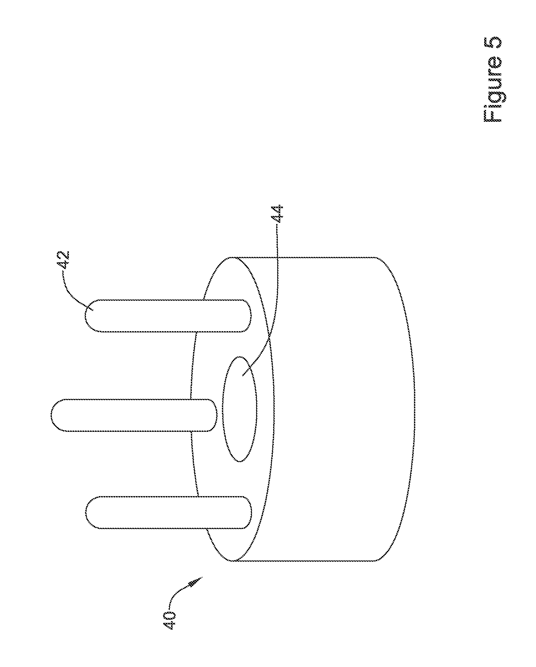
FIG. 5 illustrates an example cleat disc of an example medical device system;
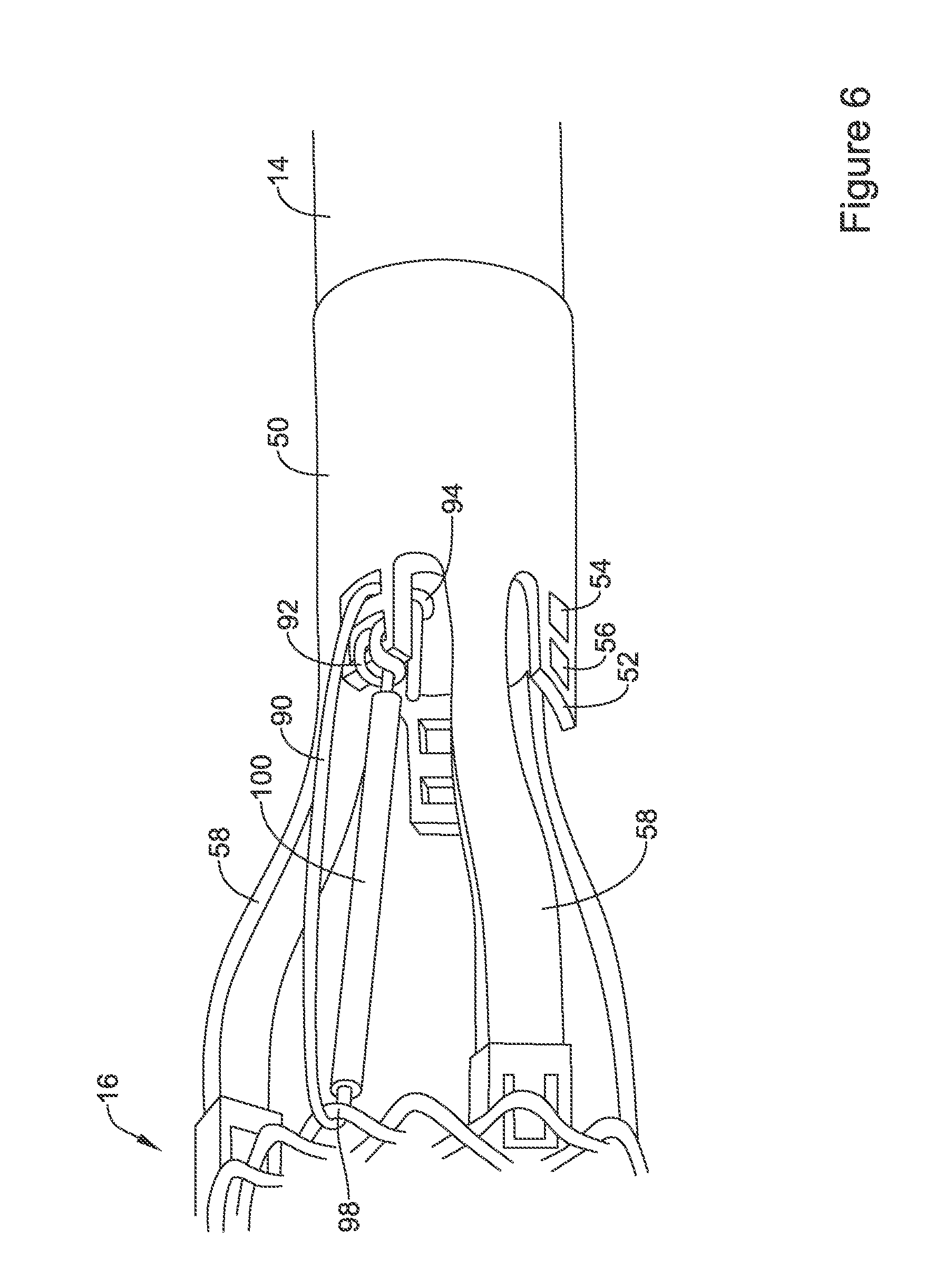
FIG. 6 illustrates selected components of an example medical device system;
FIG. 7 illustrates a partial cut-away view of selected components of an example medical device system in a deployed configuration;
FIG. 8 illustrates a partial cut-away view of selected components of an example medical device system in a partially-released configuration;
FIG. 9 illustrates a partial cut-away view of selected components of an example medical device system in a released configuration;
FIGS. 10-12 illustrate example actuation means associated with an example medical device system;
FIG. 13 illustrates selected components associated with an example medical device system;
FIG. 14 illustrates selected components associated with an example medical device system in a deployed configuration prior to sheathing of an example medical implant;
FIG. 15 illustrates selected components associated with an example medical device system in a partially-sheathed configuration during sheathing of an example medical implant;
FIG. 16 illustrates selected components associated with an example medical device system in a deployed configuration prior to sheathing of an example medical implant;
FIG. 17 illustrates selected components associated with an example medical device system in a partially-sheathed configuration during sheathing of an example medical implant;
FIG. 18 illustrates selected components associated with an example medical device system in a deployed configuration prior to sheathing of an example medical implant;
FIG. 19 illustrates selected components associated with an example medical device system at a first sheathing step of a partially-sheathed configuration prior during sheathing of an example medical implant;
FIG. 20 illustrates selected components associated with an example medical device system at a second sheathing step of a partially-sheathed configuration during sheathing of an example medical implant;
FIG. 21 illustrates selected components associated with an example medical device system in a deployed configuration prior to sheathing of an example medical implant; and
FIG. 22 illustrates selected components associated with an example medical device system in a partially-sheathed configuration during sheathing of an example medical implant.
While aspects of the disclosure are amenable to various modifications and alternative forms, specifics thereof have been shown by way of example in the drawings and will be described in detail. It should be understood, however, that the intention is not to limit aspects of the disclosure to the particular embodiments described. On the contrary, the intention is to cover all modifications, equivalents, and alternatives falling within the spirit and scope of the disclosure.
DETAILED DESCRIPTION
The following description should be read with reference to the drawings, which are not necessarily to scale, wherein like reference numerals indicate like elements throughout the several views. The detailed description and drawings are intended to illustrate but not limit the claimed invention. Those skilled in the art will recognize that the various elements described and/or shown may be arranged in various combinations and configurations without departing from the scope of the disclosure. The detailed description and drawings illustrate example embodiments of the claimed invention.
Generally speaking, in terms of the orientation of the structural elements relative to each other and the operation of the disclosed device(s), a proximal end may be considered closest to the user (or external to a patient) and a distal end farthest from the user (or internal to a patient). However, the skilled artisan will appreciate that the orientations and/or directions may be reversed as necessary or appropriate.
For the following defined terms, these definitions shall be applied, unless a different definition is given in the claims or elsewhere in this specification.
All numeric values are herein assumed to be modified by the term "about," whether or not explicitly indicated. The term "about", in the context of numeric values, generally refers to a range of numbers that one of skill in the art would consider equivalent to the recited value (i.e., having the same function or result). In many instances, the term "about" may include numbers that are rounded to the nearest significant figure. Other uses of the term "about" (i.e., in a context other than numeric values) may be assumed to have their ordinary and customary definition(s), as understood from and consistent with the context of the specification, unless otherwise specified.
The recitation of numerical ranges by endpoints includes all numbers within that range, including the endpoints (e.g. 1 to 5 includes 1, 1.5, 2, 2.75, 3, 3.80, 4, and 5).
Although some suitable dimensions, ranges and/or values pertaining to various components, features and/or specifications are disclosed, one of skill in the art, incited by the present disclosure, would understand desired dimensions, ranges and/or values may deviate from those expressly disclosed.
As used in this specification and the appended claims, the singular forms "a", "an", and "the" include plural referents unless the content clearly dictates otherwise. As used in this specification and the appended claims, the term "or" is generally employed in its sense including "and/or" unless the content clearly dictates otherwise.
Relative terms such as "proximal", "distal", "advance", "retract", variants thereof, and the like, may be generally be considered with respect to the positioning, direction, and/or operation of various elements relative to a user/operator/manipulator of the device, wherein "proximal" and "retract" indicate or refer to closer to or toward the user and "distal" and "advance" indicate or refer to farther from or away from the user. Other relative terms, such as "upstream" and "downstream" refer to a direction of fluid flow within a lumen, such as a body lumen or blood vessel.
It is noted that references in the specification to "an embodiment", "some embodiments", "other embodiments", etc., indicate that the embodiment(s) described may include a particular feature, structure, or characteristic, but every embodiment may not necessarily include the particular feature, structure, or characteristic. Moreover, such phrases are not necessarily referring to the same embodiment. Further, when a particular feature, structure, or characteristic is described in connection with an embodiment, it would be within the knowledge of one skilled in the art to effect such feature, structure, or characteristic in connection with other embodiments, whether or not explicitly described, unless clearly stated to the contrary. That is, the various individual elements described below, even if not explicitly shown in a particular combination, are nevertheless contemplated as being combinable or arrangable with each other to form other additional embodiments or to complement and/or enrich the described embodiment(s), as would be understood by one of ordinary skill in the art.
For the purpose of clarity, certain identifying numerical nomenclature (e.g., first, second, third, fourth, etc.) may be used throughout the description and/or claims to name and/or differentiate between various described and/or claimed features. It is to be understood that the numerical nomenclature is not intended to be limiting and is exemplary only. In some embodiments, alterations of and deviations from previously-used numerical nomenclature may be made in the interest of brevity and clarity. That is, a feature identified as a "first" element may later be referred to as a "second" element, a "third" element, etc. or may be omitted entirely, and/or a different feature may be referred to as the "first" element. The meaning and/or designation in each instance will be apparent to the skilled practitioner.
Diseases and/or medical conditions that impact the cardiovascular system are prevalent in the United States and throughout the world. Traditionally, treatment of the cardiovascular system was often conducted by directly accessing the impacted part of the system. For example, treatment of a blockage in one or more of the coronary arteries was traditionally treated using coronary artery bypass surgery. As can be readily appreciated, such therapies are rather invasive to the patient and require significant recovery times and/or treatments. More recently, less invasive therapies have been developed, for example, where a blocked coronary artery could be accessed and treated via a percutaneous catheter (e.g., angioplasty). Such therapies have gained wide acceptance among patients and clinicians.
Some relatively common medical conditions may include or be the result of inefficiency, ineffectiveness, or complete failure of one or more of the valves within the heart. For example, failure of the aortic valve can have a serious effect on a human and could lead to serious health condition and/or death if not dealt with. Treatment of defective heart valves poses other challenges in that the treatment often requires the repair or outright replacement of the defective valve. Such therapies may be highly invasive to the patient. Disclosed herein are medical devices that may be used for delivering a medical device to a portion of the cardiovascular system in order to diagnose, treat, and/or repair the system. At least some of the medical devices disclosed herein may be used to deliver and implant a replacement heart valve (e.g., a replacement aortic valve). In addition, the devices disclosed herein may deliver the replacement heart valve percutaneously and, thus, may be much less invasive to the patient. The devices disclosed herein may also provide a number of additional desirable features and benefits as described in more detail below.
The figures illustrate selected components and/or arrangements of a medical device system 10. It should be noted that in any given figure, some features of the medical device system 10 may not be shown, or may be shown schematically, for simplicity. Additional details regarding some of the components of the medical device system 10 may be illustrated in other figures in greater detail. A medical device system 10 may be used to deliver and/or deploy a variety of medical devices to a number of locations within the anatomy. In at least some embodiments, the medical device system 10 may include a replacement heart valve delivery system (e.g., a replacement aortic valve delivery system) that can be used for percutaneous delivery of a replacement heart valve. This, however, is not intended to be limiting as the medical device system 10 may also be used for other interventions including mitral valve replacement, valve repair, valvuloplasty, and the like, or other similar interventions.
The medical device system 10, as seen in FIG. 1 for example, may generally be described as a catheter system that includes a delivery system having an outer sheath 12 for a medical implant 16 (i.e., a replacement valve implant, for example, which term may be used interchangeably with the term "medical implant" herein) which may be coupled to the delivery system and disposed within a lumen of the outer sheath 12 during delivery of the medical implant 16. In some embodiments, the delivery system may include an inner catheter 14, as seen in FIG. 2 for example, extending at least partially through the outer sheath 12 (partially seen in phantom in FIG. 1). In some embodiments, the medical implant 16 may be coupled to the inner catheter 14 and disposed within the lumen of the outer sheath 12 during delivery of the medical implant 16. In some embodiments, a handle 18 may be disposed and/or attached at a proximal end of the delivery system, as seen in FIG. 1, and may include one or more actuation means associated therewith. In some embodiments, the handle 18 may be configured to manipulate the position of the outer sheath 12 relative to the inner catheter 14, and/or aid in the deployment of the medical implant 16. In some embodiments, the medical device system 10 may include a nose cone 64 disposed at a distal end of a guidewire extension tube 62, wherein the guidewire extension tube 62 may extend distally from the inner catheter 14. In at least some embodiments, the nose cone 64 may be designed to have an atraumatic shape. In some embodiments, the nose cone 64 may include a ridge or ledge 66 that is configured to abut a distal tip of the outer sheath 12 during delivery of the medical implant 16.
In use, the medical device system 10 may be advanced percutaneously through the vasculature to a position adjacent to an area of interest or a target location. For example, the medical device system 10 may be advanced through the vasculature and across the aortic arch to a position adjacent to a defective aortic valve. Alternative approaches to treat a defective aortic valve and/or other heart valve(s) are also contemplated with the medical device system 10. During delivery, the medical implant 16 may be generally disposed in an elongated and low profile "delivery" configuration within the delivery system and/or the outer sheath 12 coupled to and/or distal of the inner catheter 14. Once positioned, the outer sheath 12 may be retracted relative to the inner catheter 14, which may be held stationary by the handle 18, and/or the medical implant 16 to expose the medical implant 16. The medical implant 16 may be actuated using the handle 18 in order to translate the medical implant 16 into a generally expanded and larger profile "deployed" configuration suitable for implantation within the anatomy (as seen in FIG. 3, for example). When the medical implant 16 is suitably deployed within the anatomy, the medical implant 16 may be released and/or detached from the medical device system 10, the delivery system can be removed from the vasculature, leaving the medical implant 16 in place in a "released" configuration to function as, for example, a suitable replacement for the native aortic valve. In at least some interventions, the medical implant 16 may be deployed within the native valve (e.g., the native valve is left in place and not excised). Alternatively, the native valve may be removed (such as through valvuloplasty, for example) and the medical implant 16 may be deployed in its place as a replacement.
In some embodiments, the inner catheter 14 may include one or more lumens extending therethrough, as seen in FIG. 2 for example. For example, in some embodiments, the inner catheter 14 may include a first lumen, a second lumen, a third lumen, and a fourth lumen. Other configurations are also contemplated. In general, the one or more lumens extend along an entire length of the inner catheter 14. Other embodiments are contemplated, however, where one or more of the one or more lumens extend along only a portion of the length of the inner catheter 14. For example, in some embodiments, the fourth lumen may stop just short of a distal end of the inner catheter 14 and/or be filled in at its distal end to effectively end the fourth lumen proximal of the distal end of the inner catheter 14. In some embodiments, a distal region of the inner catheter 14 may include a step in outer diameter that defines a decreased diameter section 20. In some embodiments, the decreased diameter section 20 may define a region where other components of the medical device system 10 may be attached. For example, in some embodiments, a coupler assembly 78 (described further below) maybe attached to the inner catheter 14 at the decreased diameter section 20 and/or at a distal end of the inner catheter 14.
In some embodiments, the inner catheter 14 may include an extruded, multi-lumen polymeric shaft. Other forms are also contemplated including other polymer shafts or tubes, metallic shafts or tubes, reinforced shafts or tubes, or the like including other suitable materials such as those disclosed herein. In some embodiments, the inner catheter 14 may be a singular monolithic or unitary member. In some embodiments, the inner catheter 14 may include a plurality of portions or segments that are coupled together. The total length of the inner catheter 14 may be in the range of about 60 to 150 cm, or about 80 to 120 cm, or about 100 to 115 cm, or about 112.+-.0.02 cm. In some embodiments, the inner catheter 14 may have one or more sections with a differing hardness/stiffness (e.g., differing shore durometer). For example, the inner catheter 14 may have a proximal region and an intermediate region. In some embodiments, the proximal region may include a generally stiff polymeric material such as a 72D polyether block amide (e.g., 72D PEBAX) and may have a length in the range of about 60 to 150 cm, or about 80 to 120 cm, or about 100 to 115 cm, or about 109.5.+-.0.02 cm. In some embodiments, the intermediate region may include a 40D polyether block amide (e.g., 40D PEBAX) and may have a length in the range of about 5 to 25 mm, or about 10 to 20 mm, or about 15.+-.0.01 mm. The decreased outer diameter section may also differ from the proximal region and/or the intermediate region and, in some embodiments, may include a 72D polyether block amide (e.g., 72D PEBAX) and may have a length in the range of about 0.5 to 2 cm (5 to 20 mm), or about 0.8 to 1.5 cm (8 to 15 mm), or about 1.+-.0.001 cm (10.+-.0.01 mm). These are just examples.
In some embodiments, disposed within one of the lumens (e.g., a first lumen) of the inner catheter 14 may be at least one actuator element 84, which may be used to actuate (i.e., translate axially or longitudinally, and/or expand) the medical implant 16 between a delivery configuration and a deployed configuration. In some cases, the actuator element(s) 84 may herein be referred to, or used interchangeably with, the term "actuator element". In some embodiments, the medical device system 10 may include at least one actuator element 84. In some embodiments, the at least one actuator element 84 may include a plurality of actuator elements 84, two actuator elements 84, three actuator elements 84, four actuator elements 84, or another suitable or desired number of actuator elements 84. For the purpose of illustration only, the medical device system 10 and/or the medical implant 16 is shown with three actuator elements 84.
In at least some embodiments, the first lumen may be lined with a low friction liner (e.g., a FEP liner). In some embodiments, disposed within a second lumen may be at least one release pin, although dedicated release pins are not strictly necessary in every embodiment. In at least some embodiments, the second lumen may be lined with a hypotube liner. A third lumen may be a guidewire lumen and in some embodiments, the third lumen may also be lined with a hypotube liner. In some embodiments, a fourth lumen may be used to house a non-stretch wire or other reinforcing member. The form of the non-stretch wire or other reinforcing member may vary. In some embodiments, the non-stretch wire may take the form of a stainless steel braid. The non-stretch wire may optionally include a pair of longitudinally-extending aramid and/or para aramid strands (for example, KEVLAR.RTM.) disposed on opposite sides of the braid. In general, rather than being "disposed within" the fourth lumen, the non-stretch wire may be embedded within the fourth lumen. In addition, the non-stretch wire may extend to a position adjacent to a distal end region but not fully to the distal end of the inner catheter 14. For example, a short distal segment of the fourth lumen may be filled in with polymer material adjacent to the distal end of the inner catheter 14.
It is to be noted that in order to facilitate understanding, certain features of the disclosure may be described in the singular, even though those features may be plural or recurring within the disclosed embodiment(s). Each instance of the features may include and/or be encompassed by the singular disclosure(s), unless expressly stated to the contrary. For example, a reference to "the actuator element", "the locking element", "the lumen", or other features may be equally referred to all instances and quantities beyond one of said feature. As such, it will be understood that the following discussion may apply equally to any and/or all of the components for which there are more than one within the medical implant 16 (i.e., the at least one actuator element 84, the plurality of locking elements 76, the plurality of fingers 58, etc.) and/or the medical device system 10, unless explicitly stated to the contrary. Additionally, not all instances of some elements or features may be shown in each figure for clarity.
FIG. 3 illustrates some selected components of the medical device system 10 and/or the medical implant 16. For example, here it can be seen that the medical implant 16 may include a plurality of valve leaflets 68 (e.g., bovine pericardial, polymeric, etc.) which may be secured to a braided anchor member 70 that is reversibly actuatable between an elongated "delivery" configuration, and an expanded "deployed" configuration. In some embodiments, the braided anchor member 70 may form a tubular structure defining a central longitudinal axis. In some embodiments, the medical implant 16 may include a plurality of locking elements 76 attached to the braided anchor member 70, the plurality of locking elements 76 being configured to lock the braided anchor member 70 in the "deployed" and/or "released" configuration(s). In some embodiments, at least one actuator element 84 may be configured to actuate the braided anchor member 70 and/or the medical implant 16 between the "delivery" configuration and the "deployed" configuration and/or the "released" configuration.
In some embodiments, the plurality of locking elements 76 may each comprise a post member, for example at the commissure portions of the valve leaflets 68 (the post member may sometimes be referred to as a portion of a commissure post, which may serve to secure the valve leaflets 68, or the post member may be connected and/or attached to a commissure post), and a buckle member or other receiving element configured to slidably receive the post member therein. In other words, in at least some embodiments, a medical implant 16 may include a plurality of post members and a corresponding a plurality of buckle members. Other configurations and correspondences are also contemplated. In some embodiments, the valve leaflets 68 may also be secured to a base or distal end of the braided anchor member 70. The post members and/or the commissure posts, in turn, may be secured and/or attached to the braided anchor member 70 (e.g., along the interior of the braided anchor member) with sutures, adhesives, or other suitable mechanisms. In some embodiments, the commissure post and/or the post member may include one or more holes or other features provided to aid in securing and/or attaching the commissure post and/or the post member to the braided anchor member 70. Positioned adjacent to (e.g., aligned with) the plurality of post members are a corresponding plurality of buckle members, which may be secured and/or fixedly attached to the braided anchor member 70 (e.g., along the interior of the braided anchor member 70) with sutures, adhesives, or other suitable mechanisms. In some embodiments, the post member may be axially translatable relative to the buckle member generally parallel to the central longitudinal axis of the braided anchor member 70 when the post member is at least partially disposed within and/or engaged with the buckle member.
In some embodiments, one buckle member may be fixedly attached to the braided anchor member 70 adjacent to each of the three post members. Accordingly, in some embodiments, the braided anchor member 70 may have a total of three buckle members and three post members attached thereto. Similarly, one actuator element 84 may be associated with each post member and buckle member, for a total of three actuator elements 84 in the illustrated example(s). Other embodiments are contemplated where fewer or more buckle members, post members, and/or actuator elements 84 may be utilized. In some embodiments, a seal 74 (shown in partial cross-section in FIG. 3) may be disposed on and/or about the braided anchor member 70 and may help to seal the medical implant 16 within a target site or area of interest upon deployment.
In at least some embodiments, the buckle member may be configured to slidably receive at least a portion of the post member within the longitudinal channel. In some embodiments, the buckle member may include one or more holes or other features provided to aid in attaching the buckle member to the braided anchor member 70. In some embodiments, the buckle member may be configured to engage with and/or lock the post member in the "deployed" configuration, such that distal axial translation of the post member relative to the buckle member is prevented. Some suitable but non-limiting materials for the buckle member and/or the post member, for example metallic materials or polymeric materials, may be described below.
In some embodiments, attachment between the medical implant 16 and the inner catheter 14 and/or the delivery system may be effected through the use of a coupler assembly 78, as seen in FIGS. 2-3 for example. In at least some embodiments, the coupler assembly 78 may generally include a coupler ring 50 disposed about and/or fixedly attached to the decreased diameter section 20 and/or at a distal end of the inner catheter 14. In some embodiments, the coupler assembly 78 may include a plurality of fingers 58 extending distally from the coupler ring 50. In some embodiments, each of the plurality of fingers 58 may be releasably coupled to one locking element 76 of the medical implant 16. As such, the medical implant 16 may include a plurality of locking elements 76 corresponding to the plurality of fingers 58. A collar 80 may further assist in holding together these structures. A guide 82 may be disposed over each of the fingers 58 and may serve to keep the plurality of fingers 58 of the coupler assembly 78 associated with the at least one actuator element 84 extending adjacent to the coupler assembly 78.
In some embodiments, an example actuator element 84 may include a proximal end and a distal end. In use, the proximal end may be connected to the handle 18, and/or manipulated or otherwise actuated by a user using the handle 18, to shift the braided anchor member 70 and/or the medical implant 16 from a "delivery" configuration to a "deployed" configuration, and later to a "released" configuration. In some embodiments, the actuator element 84 may include an elongated rod and a distal end portion. In some embodiments, the actuator element 84 and/or the distal end portion may be releasably connected to and/or coupled to the locking element 76. In some embodiments, the distal end portion may be integrally formed with or as a part of the elongated rod as a single monolithic structure. In some embodiments, the actuator element 84 may be prevented from rotating (i.e., is non-rotatable) relative to the locking element 76 when the actuator element 84 is engaged with the locking element 76. In some embodiments, after shifting the braided anchor member 70 and/or the medical implant 16 from the "delivery" configuration to the "deployed" configuration, continued proximal retraction, withdrawal, and/or translation of the at least one actuator element 84 may shift the braided anchor member 70 and/or the medical implant 16 from the "deployed" configuration to the "released" configuration. When shifting the braided anchor member 70 and/or the medical implant 16 from the "deployed" configuration to the "released" configuration, the distal end portion of the at least one actuator element 84 may engage with the collar 80, thereby retracting, withdrawing, and/or translating proximally the collar 80 relative to the locking element 76 to release the braided anchor member 70 and/or the medical implant 16.
In some embodiments, the actuator element 84 and/or the elongated rod may be generally round, oblong, ovoid, rectangular, polygonal (i.e., two-sided, three-sided, four-sided, five-sided, six-sided, etc.) and/or combinations thereof in shape. Other shapes, both regular and irregular, are also contemplated. In some embodiments, the actuator element 84 may be formed from a single piece of wire, round stock, or other suitable material, as discussed herein. In some embodiments, the actuator element 84 may be formed by further processing the single piece of wire, round stock, or other suitable material, such as by machining, stamping, laser cutting, etc. Some suitable but non-limiting materials for the actuator element 84, the elongated rod, and/or the distal end portion, for example metallic materials or polymeric materials, may be described below.
As seen in greater detail in FIG. 4, which shows a modified, partially splayed-out end view of the distal end of the inner catheter 14, in some embodiments, the coupler assembly 78 may include one or more suture anchors 52 extending distally from the coupler ring 50, each suture anchor 52 including a proximal aperture 54 extending laterally and/or radially therethrough, and a distal aperture 56 extending laterally and/or radially therethrough relative to a central longitudinal axis of the inner catheter 14. In some embodiments, the proximal aperture 54 may be distinct and/or separate from the distal aperture 56. Also visible in FIG. 4 is a cleat disc 40 (e.g., a release mechanism, a release element, etc., which terms may be used interchangeably with a cleat disc herein), which may be disposed distal of the inner catheter 14 and/or within the coupler assembly 78. In at least some embodiments, the cleat disc 40 may be at least partially disposed within a lumen of the coupler ring 50. In some embodiments, the cleat disc 40 may include one or more cleat posts 42 (e.g., one or more release pins, one or more protrusions, etc., which terms may be used interchangeably with one or more cleats herein) extending distally therefrom, as seen in FIGS. 4-5 for example. In some embodiments, the one or more cleat posts 42 may comprise two cleats, three cleats, four cleats, or another suitable number of cleats. In some embodiments, the one or more cleat posts 42 may be fixedly attached to the cleat disc 40. In some embodiments, the one or more cleat posts 42 may be integrally formed with the cleat disc 40 as a single unitary structure. In some embodiments, the cleat disc 40 may include an actuator lumen 44 extending therethrough. In at least some embodiments, the at least one actuator element 84 may extend through the actuator lumen 44 of the cleat disc 40.
In some embodiments, a sheathing aid 200 may extend between and/or connect the delivery system to the medical implant 16. In some embodiments, the sheathing aid 200 may be configured to guide the medical implant 16 into the outer sheath 12 upon relative closing movement therebetween, as will be described in more detail below. In some embodiments, the sheathing aid 200 may include a plurality of filaments 90 (e.g., a plurality of tethers, a plurality of tensioning elements, a plurality of sutures, etc., which terms may be used interchangeably with a plurality of filaments herein) extending distally from the inner catheter 14 and/or one suture anchor 52 to a proximal end of the braided anchor member 70 of the medical implant 16. In at least some embodiments, the plurality of filaments 90 may be releasably coupled to the cleat disc 40 and/or the one or more cleat posts 42.
Also illustrated in FIGS. 4 and 6 is one of a plurality of filaments 90 extending distally from the inner catheter 14 and/or one suture anchor 52 to a proximal end of the braided anchor member 70 of the medical implant 16. In some embodiments, each of the plurality of filaments 90 may include a first end having a first end loop 92 and a second end having a second end loop 94. In some embodiments, each of the plurality of filaments 90 may include a filament body extending between the first end and the second end, the filament body having a tubular member 100 (e.g., a thin-walled hypotube, etc.) disposed thereon. The first end loop 92 may extend through the distal aperture 56 and toward a distalmost end of the suture anchor 52, where the filament body may pass through the first end loop 92, thereby securing the first end of the filament 90 to the suture anchor 52. The filament body may then extend distally toward the proximal end of the braided anchor member 70 of the medical implant 16, where the filament body extends through and/or loops around a crown 98 of the braided anchor member 70. The filament body then extends back proximally toward the suture anchor 52, wherein the second end loop 94 extends through the proximal aperture 54 and into or within the lumen of the coupler ring 50. At a location within the coupler ring 50, the second end loop 94 extends over and/or around one of the one or more cleat posts 42 to releasably coupling the filament 90 to the cleat disc 40, the suture anchor 52, the coupler ring 50, and/or the coupler assembly 78.
In other words, one of the one or more cleat posts 42 extends through the second end loop 94 when the cleat disc 40 is disposed at a distal position within the lumen of the coupler ring 50 to releasably couple the filament 90 thereto, as seen in FIG. 7 for example. In the distal position, the one or more cleat posts 42 extend distally past the proximal aperture 54 such that the second end loop(s) 94 cannot be removed from the cleat post(s) 42 and/or pulled through the proximal aperture 54. The skilled person will recognize that, if desired, the arrangement of the end loops through the apertures may be reversed within the scope of this disclosure such that the second end loop 94 extends through the distal aperture 56 and the first end loop 92 extends through the proximal aperture 54. Other configurations are also contemplated.
As will become apparent from the discussion below and other figures associated with the disclosure, in some embodiments, one of the plurality of filaments 90 may extend between each crown 98 of the braided anchor member 70 and the distal end of the inner catheter 14, the coupler ring 50, the coupler assembly 78, and/or the suture anchor 52. In some embodiments, more than one of the plurality of filaments 90 may be coupled to each cleat post 42, as seen illustratively in FIG. 7 for example. In some embodiments, two of the plurality of filaments 90 may be coupled to each cleat post 42, three of the plurality of filaments 90 may be coupled to each cleat post 42, four of the plurality of filaments 90 may be coupled to each cleat post 42, five of the plurality of filaments 90 may be coupled to each cleat post 42, six of the plurality of filaments 90 may be coupled to each cleat post 42, etc.
In some embodiments, each filament 90 of the plurality of filaments 90 extending through and/or looping around a crown 98 of the braided anchor member 70 disposed between adjacent fingers 58 may extend to one suture anchor 52 (e.g., the same suture anchor 52) that is also disposed between the same adjacent fingers 58 and may be secured to one cleat post 42 (e.g., the same cleat post 42). In general, the medical device system 10 may include one filament 90 (e.g., only one filament 90, exactly one filament 90, a single filament 90, etc.) of the plurality of filaments 90 extending through and/or looping around any given crown 98 of the braided anchor member 70, although other configurations are contemplated. In some embodiments, not all crowns 98 of the braided anchor member 70 include a filament 90 of the plurality of filaments 90 extending through and/or looping around them. In other words, in some embodiments, some of the crowns 98 (e.g., some quantity less than all) may include a filament 90 of the plurality of filaments 90 extending through and/or looping around them.
In some embodiments, the at least one actuator element 84 may include an enlarged portion and/or an additional structural feature (e.g., a tubular sleeve, etc.) disposed thereon distal of the cleat disc 40 and proximal to a distal end of the at least one actuator element 84, as will be described in more detail below with reference to FIGS. 10-12. During the release process for the medical implant 16, (e.g., as the medical implant 16 is actuated from the "delivery" configuration to the "deployed" configuration to the "released" configuration), the at least one actuator element 84 may be retracted, withdrawn, and/or translated proximally relative to the inner catheter 14, the medical implant 16, and/or the braided anchor member 70. As the at least one actuator element 84 is retracted, withdrawn, and/or translated proximally, the enlarged portion and/or the additional structural feature (e.g., a tubular sleeve, etc.) may contact the cleat disc 40 when the cleat disc 40 is in the distal position, wherein continued retraction, withdrawal, and/or proximal translation of the at least one actuator element 84 may pull, slide, and/or translate the cleat disc 40 proximally within the lumen of the coupler ring 50 toward a proximal position, as seen in FIG. 8 for example, to release the plurality of filaments 90 from the one or more cleat posts 42. In some embodiments, proximal retraction and/or translation of the cleat disc 40 to the proximal position may move and/or translate the one or more cleat posts 42 such that the one or more cleat posts 42 no longer extend distally past the proximal aperture 54, thereby allowing the second end loop(s) 94 to be removed from the cleat post(s) 42 and/or allowing the second end loop(s) 94 to be pulled through the proximal aperture 54, as seen in FIG. 9 for example. In some embodiments, proximal retraction and/or translation of the cleat disc 40 to the proximal position may move and/or translate the one or more cleat posts 42 such that the one or more cleat posts 42 are pulled proximally through and/or are removed from the second end loop(s) 94, thereby allowing the second end loop(s) 94 to be pulled through the proximal aperture 54, as seen in FIG. 9 for example.
Once the cleat disc 40 has been pulled to the proximal position and/or the second end loop(s) 94 is pulled through the proximal aperture 54, continued proximal retraction, withdrawal, and/or proximal translation of the at least one actuator element 84 may pull the plurality of filaments 90 through the crowns 98 of the braided anchor member 70 and pull the plurality of fingers 58 away from the corresponding plurality of locking elements 76 to complete the transition of the medical implant 16 from the "deployed" configuration to the "released" configuration. The inner catheter 14 and/or the coupler assembly 78 may be re-sheathed within the outer sheath 12 via relative translation therebetween (e.g., advancing the outer sheath 12 distally over the inner catheter 14 and/or the coupler assembly 78, withdrawing the inner catheter 14 and/or the coupler assembly 78 proximally within the outer sheath 12, a combination thereof, etc.). Thereafter, the delivery system may be withdrawn and/or removed from the anatomy, leaving behind the expanded and deployed medical implant 16 disposed at the target site in a "released" configuration.
FIGS. 10-12 illustrate example configurations for the at least one actuator element 84, wherein the each of the at least one actuator element 84 may include an enlarged portion 86 (e.g., a ferrule, a protrusion, a stop element, etc.) and/or a tubular sleeve 88 disposed over the at least one actuator element 84. In at least some embodiments, the enlarged portion 86 and/or the tubular sleeve 88 have an outer diameter greater than an outer diameter of the at least one actuator element 84. It is noted that FIGS. 10-12 illustrate a single complete actuator element 84, and only selected portions of other features for clarity and ease of understanding. In some embodiments, the enlarged portion 86 and/or the tubular sleeve 88 may be disposed distal of the cleat disc 40 and may be disposed proximal of the plurality of locking elements 76 and/or the collar 80. In other words, the enlarged portion 86 and/or the tubular sleeve 88 may be disposed between the cleat disc 40 and the medical implant 16.
Upon deployment of the medical implant 16, proximal retraction, withdrawal, and/or proximal translation of the at least one actuator element 84 through the actuator lumen 44 of the cleat disc 40 may engage the enlarged portion 86 and/or the tubular sleeve 88 against a distal face of the cleat disc 40 in the distal position. In some embodiments, as seen in FIG. 10 for example, the enlarged portion 86 of each of the at least one actuator element 84, when combined, form an outer diameter and/or cross-sectional area that is greater than a diameter of the actuator lumen 44 of the cleat disc 40. As such, the combined enlarged portions 86 cannot be pulled, withdrawn, and/or translated through the cleat disc 40.
In some embodiments, as seen in FIG. 11 for example, each of the at least one actuator element 84 may include a tubular sleeve 88 disposed thereon. Proximal retraction, withdrawal, and/or proximal translation of the at least one actuator element 84 causes the collar 80 to also retract, withdraw, and/or translate proximally. As the collar 80 moves proximally, a proximal end of the collar 80 engages a distal end of the tubular sleeve 88 causing a proximal end of the tubular sleeve 88 to retract, withdraw, and/or translate proximally into engagement and/or contact with the distal face of the cleat disc 40 in the distal position. When combined, the tubular sleeve 88 of each of the at least one actuator element 84 forms an outer diameter and/or cross-sectional area that is greater than the diameter of the actuator lumen 44 of the cleat disc 40. As such, the combined tubular sleeves 88 cannot be pulled, withdrawn, and/or translated through the cleat disc 40.
In some embodiments, as seen in FIG. 12 for example, each of the at least one actuator element 84 may include an enlarged portion 86 disposed thereon, and a tubular sleeve 88 may be disposed about all of the at least one actuator element 84 such that all of the at least one actuator element 84 pass through the tubular sleeve 88. In this way, the tubular sleeve 88 has an outer diameter and/or cross-section greater than the diameter of the actuator lumen 44 of the cleat disc 40, and the enlarged portion 86 of each of the at least one actuator element 84, when combined, form an outer diameter and/or cross-sectional area that is greater than an inner diameter of the tubular sleeve 88. As such, the combined enlarged portions 86 cannot be pulled, withdrawn, and/or translated through the tubular sleeve 88. When the at least one actuator element 84 is retracted proximally, withdrawn, and/or translated proximally, the enlarged portion 86 engages a distal end of the tubular sleeve 88 and a proximal end of the tubular sleeve 88 engages the distal face of the cleat disc 40.
In each of the examples shown in FIGS. 10-12, further proximal retraction, withdrawal, and/or proximal translation of the at least one actuator element 84 may move the cleat disc 40 proximally toward the proximal position after the braided anchor member 70 and/or the medical implant 16 has been shifted to the "deployed" configuration, and/or as the braided anchor member 70 and/or the medical implant 16 is actuated and/or shifted from the "deployed" configuration to the "released" configuration.
FIG. 13 illustrates an example filament 90 having a tubular member 100 disposed thereon. The filament 90 may include a first end having first end loop 92 and a second end having a second end loop 94, as described above. In some embodiments, a filament body of the filament 90 extending between the first end loop 92 and the second end loop 94 may be longer than the tubular member 100 to facilitate extending the filament 90 back to the suture anchor 52 from the crown 98 of the braided anchor member 70. In some embodiments, the filament body of the filament 90 extending between the first end loop 92 and the second end loop 94 may be 25-100% longer than the tubular member 100 to facilitate extending the filament 90 back to the suture anchor 52 from the crown 98 of the braided anchor member 70. In some embodiments, the filament body of the filament 90 extending between the first end loop 92 and the second end loop 94 may be 50-100% longer than the tubular member 100 to facilitate extending the filament 90 back to the suture anchor 52 from the crown 98 of the braided anchor member 70. In some embodiments, the filament body of the filament 90 extending between the first end loop 92 and the second end loop 94 may be more than 100% longer than the tubular member 100 to facilitate extending the filament 90 back to the suture anchor 52 from the crown 98 of the braided anchor member 70.
As mentioned above, in some embodiments, the medical device system 10 may include a sheathing aid 200 extending between and/or connecting the delivery system, the inner catheter 14, and/or the coupler ring 50 to the medical implant 16. In some embodiments, the sheathing aid 200 may be configured to guide the medical implant 16 into the outer sheath 12 upon relative closing movement therebetween. The medical device system 10, through the use of the various components thereof, may be configured to allow a user (e.g., clinician, etc.) to "sheath", "unsheath", and "resheath" the medical implant 16. In other words, a user may manipulate the medical device system 10 so that the medical implant 16 shifts from an unsheathed configuration where the medical implant 16 is positioned generally outside of the outer sheath 12 to a sheathed or "delivery" configuration where the medical implant 16 is positioned within the outer sheath 12 (e.g., the user can "sheath" the medical implant 16). In addition, a user can also manipulate the medical device system 10 so that the medical implant 16 can shift from the sheathed or "delivery" configuration to an unsheathed or "deployed" configuration (e.g., the user can "unsheath" or "deploy" the medical implant 16). Moreover, the user can manipulate the medical device system 10 so that the medical implant 16 can again shift from the unsheathed or "deployed" configuration back to the sheathed or "delivery" configuration (e.g., the user can "resheath" the medical implant 16).
Because of the relatively compact nature of the medical device system 10 and the tendency for portions of the medical device system 10 (e.g., the medical implant 16) to be biased radially outward, the sheathing/unsheathing/re-sheathing processes may exert forces on, for example, the outer sheath 12. In addition, the configuration of the braided anchor member 70 may include a number of "crowns" 98 at a proximal end thereof, which may correspond to the portions of the braided anchor member 70 where the wire(s) forming the braided anchor member 70 extends to a proximalmost extent. The crowns 98 may define a number of discrete locations where the plurality of filaments 90 engages and/or wraps over or around the braided anchor member 70. In some embodiments, the sheathing aid 200 may engage some of the crowns 98. In some embodiments, the sheathing aid 200 may engage all of the crowns 98. However, in some embodiments, the crowns 98 disposed radially adjacent to the locking elements 76 may not be engaged by sheathing aid 200, since the locking elements 76 are engaged by the plurality of fingers 58. The plurality of filaments 90 of the sheathing aid 200 may engage and/or wrap over or around the crowns 98 disposed between the locking elements 76.
FIGS. 14-15 illustrate an example sheathing aid 200 including a plurality of filaments 90 extending from the inner catheter 14 and/or the coupler ring 50 to a proximal end of the braided anchor member 70 and/or the medical implant 16. At least some of the plurality of filaments 90 of the sheathing aid 200 may include a tubular member 100 disposed thereon. In some embodiments, the at least some of the plurality of filaments 90 may comprise all of the plurality of filaments 90. In other words, each of the plurality of filaments 90 of the sheathing aid 200 may include a tubular member 100 disposed thereon. Each tubular member 100 may have a length, and in some embodiments, the length of all of the tubular members 100 may be substantially similar and/or the same. FIG. 14 illustrates a portion of the medical device system 10 in an "unsheathed" or "deployed" configuration. As the inner catheter 14 and/or the medical implant 16 is retracted, withdrawn, and/or translated proximally relative to the outer sheath 12 (and/or the outer sheath 12 is advanced distally relative to the inner catheter 14 and/or the medical implant 16), the plurality of filaments 90 and the tubular members 100 disposed thereon may contact a distal end of the outer sheath 12. In some embodiments, the plurality of filaments 90 and the tubular members 100 may act as levers against the distal end of the outer sheath 12 to provide a mechanical advantage for collapsing the braided anchor member 70 toward the "sheathed" or "delivery" configuration. FIG. 15 illustrates a portion of the medical device system 10 in a partially-sheathed configuration wherein the proximal end of the braided anchor member 70 and/or the medical implant 16 has been collapsed to a diameter similar to an inner diameter of the outer sheath 12.
Due to the attachment of the plurality of filaments 90 and/or the plurality of fingers 58 to each crown 98 of the braided anchor member 70, none of the crowns 98 may protrude radially outward to interfere with and/or catch or snag on the distal end of the outer sheath 12 during sheathing. Attaching the plurality of filaments 90 and/or the plurality of fingers 58 to each crown 98 of the braided anchor member 70 also distributes retraction and/or pulling forces among all of the crowns 98. Additionally, due to the use of a plurality of filaments 90 to attach to the crowns 98 and/or to serve as a sheathing aid 200, an overall outer profile of the braided anchor member 70 and/or the medical implant 16 may be reduced compared to a medical device system having a sheathing aid which is positioned along an outer surface of the braided anchor member 70, thereby reducing sheathing and unsheathing (e.g., deployment) forces and/or permitting a smaller diameter outer sheath 12 to be used, for example.
FIGS. 16-20 illustrate an example sheathing aid 200 including a plurality of filaments 90 extending from the inner catheter 14 and/or the coupler ring 50 to a proximal end of the braided anchor member 70 and/or the medical implant 16. At least some of the plurality of filaments 90 of the sheathing aid 200 may include a tubular member 100 disposed thereon. In some embodiments, the at least some of the plurality of filaments 90 may comprise all of the plurality of filaments 90. In other words, each of the plurality of filaments 90 of the sheathing aid 200 may include a tubular member 100 disposed thereon. Each tubular member 100 may have a length, and in some embodiments, the length of the tubular members 100 may vary. FIGS. 16 and 18 illustrate a portion of the medical device system 10 in an "unsheathed" or "deployed" configuration. As the inner catheter 14 and/or the medical implant 16 is retracted, withdrawn, and/or translated proximally relative to the outer sheath 12 (and/or the outer sheath 12 is advanced distally relative to the inner catheter 14 and/or the medical implant 16), the plurality of filaments 90 and the tubular members 100 disposed thereon may contact a distal end of the outer sheath 12. In some embodiments, the plurality of filaments 90 and the tubular members 100 may act as levers against the distal end of the outer sheath 12 to provide a mechanical advantage for collapsing the braided anchor member 70 toward the "sheathed" or "delivery" configuration. FIGS. 17, 19, and 20 illustrate a portion of the medical device system 10 in partially-sheathed configurations wherein the proximal end of the braided anchor member 70 and/or the medical implant 16 has been partially collapsed toward an inner diameter of the outer sheath 12.
As may be seen, particular with respect to FIGS. 18-20, the varying lengths of the tubular members 100 may provide a sequential sheathing process wherein selected crowns 98 are collapsed radially inward at different times and/or positions in the sheathing process as the tubular members 100 come into contact with the distal end of the outer sheath 12. For example, in some embodiments, the tubular members 100 may include one or more first tubular members 102 having a first length and one or more second tubular members 104 having a second length shorter than the first length.
In some embodiments, at a first distance (L1) between the proximal end of the braided anchor member 70 and/or the medical implant 16 and the distal end of the outer sheath 12, the first tubular members may engage the distal end of the outer sheath 12. At the first distance (L1), the filaments 90 having the first tubular members 102 disposed thereon may form a first diameter (Db) and the filaments 90 having the second tubular members 104 disposed thereon may form a second diameter (Da), as seen in FIG. 18. At a second distance (L2) between the proximal end of the braided anchor member 70 and/or the medical implant 16 and the distal end of the outer sheath 12, the second distance (L2) being less than the first distance (L1), the filaments 90 having the first tubular members 102 disposed thereon may be reduced to a third diameter (Db1) less than the first diameter (Db) and the filaments 90 having the second tubular members 104 disposed thereon may maintain the second diameter (Da), as seen in FIG. 19. At a third distance (L3) between the proximal end of the braided anchor member 70 and/or the medical implant 16 and the distal end of the outer sheath 12, the third distance (L3) being less than the first distance (L1) and the second distance (L2), the filaments 90 having the first tubular members 102 disposed thereon may be even further reduced to a fourth diameter (Db2) less than the third diameter (Db1) and the filaments 90 having the second tubular members 104 disposed thereon may be reduced to a fifth diameter (Da1) less than the second diameter (Da), as seen in FIG. 20.
Due to the attachment of the plurality of filaments 90 and/or the plurality of fingers 58 to each crown 98 of the braided anchor member 70, none of the crowns 98 may protrude radially outward to interfere with and/or catch or snag on the distal end of the outer sheath 12 during sheathing. Attaching the plurality of filaments 90 and/or the plurality of fingers 58 to each crown 98 of the braided anchor member 70 also distributes retraction and/or pulling forces among all of the crowns 98. Additionally, due to the use of a plurality of filaments 90 to attach to the crowns 98 and/or to serve as a sheathing aid 200, an overall outer profile of the braided anchor member 70 and/or the medical implant 16 may be reduced compared to a medical device system having a sheathing aid which is positioned along an outer surface of the braided anchor member 70, thereby reducing sheathing and unsheathing (e.g., deployment) forces and/or permitting a smaller diameter outer sheath 12 to be used, for example.
FIGS. 21-22 illustrate an example sheathing aid 200 including a plurality of filaments 90 extending from the inner catheter 14 and/or the coupler ring 50 to a proximal end of the braided anchor member 70 and/or the medical implant 16. In contrast to the example sheathing aids shown in FIGS. 14-20, FIGS. 21-22 illustrate an example sheathing aid 200 lacking the tubular members 100 disposed on the plurality of filaments 90. FIG. 21 illustrates a portion of the medical device system 10 in an "unsheathed" or "deployed" configuration. As the inner catheter 14 and/or the medical implant 16 is retracted, withdrawn, and/or translated proximally relative to the outer sheath 12 (and/or the outer sheath 12 is advanced distally relative to the inner catheter 14 and/or the medical implant 16), the plurality of filaments 90 may contact a distal end of the outer sheath 12. In some embodiments, the plurality of filaments 90 may act as levers against the distal end of the outer sheath 12 for collapsing the braided anchor member 70 toward the "sheathed" or "delivery" configuration. FIG. 22 illustrates a portion of the medical device system 10 in a partially-sheathed configuration wherein the proximal end of the braided anchor member 70 and/or the medical implant 16 has not been collapsed due to pinching of the plurality of filaments 90. Such a configuration may result in increased sheathing forces compared to the configurations previously illustrated herein. However, due to the attachment of the plurality of filaments 90 and/or the plurality of fingers 58 to each crown 98 of the braided anchor member 70, retraction and/or pulling forces may be distributed among all of the crowns 98, and an overall outer profile of the braided anchor member 70 and/or the medical implant 16 may be reduced compared to a medical device system having a sheathing aid which is positioned along an outer surface of the braided anchor member 70, thereby permitting a smaller diameter outer sheath 12 to be used, for example.
The materials that can be used for the various components of the medical device system 10 (and/or other systems disclosed herein) and the various elements thereof disclosed herein may include those commonly associated with medical devices. For simplicity purposes, the following discussion makes reference to the delivery system and/or the medical implant 16. However, this is not intended to limit the devices and methods described herein, as the discussion may be applied to other elements, members, components, or devices disclosed herein, such as, but not limited to, the braided anchor member 70, the actuator element 84, the sheathing aid 200, the coupler assembly 78, the post member, the buckle member, etc. and/or elements or components thereof.
In some embodiments, the medical device system 10, the delivery system, the sheathing aid 200, and/or the medical implant 16, and/or components thereof, may be made from a metal, metal alloy, polymer (some examples of which are disclosed below), a metal-polymer composite, ceramics, combinations thereof, and the like, or other suitable material.
Some examples of suitable polymers may include polytetrafluoroethylene (PTFE), ethylene tetrafluoroethylene (ETFE), fluorinated ethylene propylene (FEP), polyoxymethylene (POM, for example, DELRIN.RTM. available from DuPont), polyether block ester, polyurethane (for example, Polyurethane 85A), polypropylene (PP), polyvinylchloride (PVC), polyether-ester (for example, ARNITEL.RTM. available from DSM Engineering Plastics), ether or ester based copolymers (for example, butylene/poly(alkylene ether) phthalate and/or other polyester elastomers such as HYTREL.RTM. available from DuPont), polyamide (for example, DURETHAN.RTM. available from Bayer or CRISTAMID.RTM. available from Elf Atochem), elastomeric polyamides, block polyamide/ethers, polyether block amide (PEBA, for example available under the trade name PEBAX.RTM.), ethylene vinyl acetate copolymers (EVA), silicones, polyethylene (PE), Marlex high-density polyethylene, Marlex low-density polyethylene, linear low density polyethylene (for example REXELL.RTM.), polyester, polybutylene terephthalate (PBT), polyethylene terephthalate (PET), polytrimethylene terephthalate, polyethylene naphthalate (PEN), polyetheretherketone (PEEK), polyimide (PI), polyetherimide (PEI), polyphenylene sulfide (PPS), polyphenylene oxide (PPO), poly paraphenylene terephthalamide (for example, KEVLAR.RTM.), polysulfone, nylon, nylon-12 (such as GRILAMID.RTM. available from EMS American Grilon), perfluoro(propyl vinyl ether) (PFA), ethylene vinyl alcohol, polyolefin, polystyrene, epoxy, polyvinylidene chloride (PVdC), poly(styrene-b-isobutylene-b-styrene) (for example, SIBS and/or SIBS 50A), polycarbonates, ionomers, biocompatible polymers, other suitable materials, or mixtures, combinations, copolymers thereof, polymer/metal composites, and the like.
Some examples of suitable metals and metal alloys include stainless steel, such as 304V, 304L, and 316LV stainless steel; mild steel; nickel-titanium alloy such as linear-elastic and/or super-elastic nitinol; other nickel alloys such as nickel-chromium-molybdenum alloys (e.g., UNS: N06625 such as INCONEL.RTM. 625, UNS: N06022 such as HASTELLOY.RTM. C-22.RTM., UNS: N10276 such as HASTELLOY.RTM. C276.RTM., other HASTELLOY.RTM. alloys, and the like), nickel-copper alloys (e.g., UNS: N04400 such as MONEL.RTM. 400, NICKELVAC.RTM. 400, NICORROS.RTM. 400, and the like), nickel-cobalt-chromium-molybdenum alloys (e.g., UNS: R30035 such as MP35-N.RTM. and the like), nickel-molybdenum alloys (e.g., UNS: N10665 such as HASTELLOY.RTM. ALLOY B2.RTM.), other nickel-chromium alloys, other nickel-molybdenum alloys, other nickel-cobalt alloys, other nickel-iron alloys, other nickel-copper alloys, other nickel-tungsten or tungsten alloys, and the like; cobalt-chromium alloys; cobalt-chromium-molybdenum alloys (e.g., UNS: R30003 such as ELGILOY.RTM., PHYNOX.RTM., and the like); platinum enriched stainless steel; titanium; combinations thereof; and the like; or any other suitable material.
As alluded to herein, within the family of commercially available nickel-titanium or nitinol alloys, is a category designated "linear elastic" or "non-super-elastic" which, although may be similar in chemistry to conventional shape memory and super elastic varieties, may exhibit distinct and useful mechanical properties. Linear elastic and/or non-super-elastic nitinol may be distinguished from super elastic nitinol in that the linear elastic and/or non-super-elastic nitinol does not display a substantial "superelastic plateau" or "flag region" in its stress/strain curve like super elastic nitinol does. Instead, in the linear elastic and/or non-super-elastic nitinol, as recoverable strain increases, the stress continues to increase in a substantially linear, or a somewhat, but not necessarily entirely linear relationship until plastic deformation begins or at least in a relationship that is more linear than the super elastic plateau and/or flag region that may be seen with super elastic nitinol. Thus, for the purposes of this disclosure linear elastic and/or non-super-elastic nitinol may also be termed "substantially" linear elastic and/or non-super-elastic nitinol.
In some cases, linear elastic and/or non-super-elastic nitinol may also be distinguishable from super elastic nitinol in that linear elastic and/or non-super-elastic nitinol may accept up to about 2-5% strain while remaining substantially elastic (e.g., before plastically deforming) whereas super elastic nitinol may accept up to about 8% strain before plastically deforming. Both of these materials can be distinguished from other linear elastic materials such as stainless steel (that can also be distinguished based on its composition), which may accept only about 0.2 to 0.44 percent strain before plastically deforming.
In some embodiments, the linear elastic and/or non-super-elastic nickel-titanium alloy is an alloy that does not show any martensite/austenite phase changes that are detectable by differential scanning calorimetry (DSC) and dynamic metal thermal analysis (DMTA) analysis over a large temperature range. For example, in some embodiments, there may be no martensite/austenite phase changes detectable by DSC and DMTA analysis in the range of about -60 degrees Celsius (.degree. C.) to about 120.degree. C. in the linear elastic and/or non-super-elastic nickel-titanium alloy. The mechanical bending properties of such material may therefore be generally inert to the effect of temperature over this very broad range of temperature. In some embodiments, the mechanical bending properties of the linear elastic and/or non-super-elastic nickel-titanium alloy at ambient or room temperature are substantially the same as the mechanical properties at body temperature, for example, in that they do not display a super-elastic plateau and/or flag region. In other words, across a broad temperature range, the linear elastic and/or non-super-elastic nickel-titanium alloy maintains its linear elastic and/or non-super-elastic characteristics and/or properties.
In some embodiments, the linear elastic and/or non-super-elastic nickel-titanium alloy may be in the range of about 50 to about 60 weight percent nickel, with the remainder being essentially titanium. In some embodiments, the composition is in the range of about 54 to about 57 weight percent nickel. One example of a suitable nickel-titanium alloy is FHP-NT alloy commercially available from Furukawa Techno Material Co. of Kanagawa, Japan. Other suitable materials may include ULTANIUM.TM. (available from Neo-Metrics) and GUM METAL.TM. (available from Toyota). In some other embodiments, a superelastic alloy, for example a superelastic nitinol can be used to achieve desired properties.
In at least some embodiments, portions or all of the delivery system, the sheathing aid 200, and/or the medical implant 16, and/or components thereof, may also be doped with, made of, or otherwise include a radiopaque material. Radiopaque materials are understood to be materials capable of producing a relatively bright image on a fluoroscopy screen or another imaging technique during a medical procedure. This relatively bright image aids the user of the medical device system 10 in determining its location. Some examples of radiopaque materials can include, but are not limited to, gold, platinum, palladium, tantalum, tungsten alloy, polymer material loaded with a radiopaque filler, and the like. Additionally, other radiopaque marker bands and/or coils may also be incorporated into the design of the medical device system 10 to achieve the same result.
In some embodiments, a degree of Magnetic Resonance Imaging (MRI) compatibility is imparted into the medical device system 10. For example, the delivery system and/or the medical implant 16, and/or components or portions thereof, may be made of a material that does not substantially distort the image and create substantial artifacts (i.e., gaps in the image). Certain ferromagnetic materials, for example, may not be suitable because they may create artifacts in an MRI image. The delivery system and/or the medical implant 16, or portions thereof, may also be made from a material that the MRI machine can image. Some materials that exhibit these characteristics include, for example, tungsten, cobalt-chromium-molybdenum alloys (e.g., UNS: R30003 such as ELGILOY.RTM., PHYNOX.RTM., and the like), nickel-cobalt-chromium-molybdenum alloys (e.g., UNS: R30035 such as MP35-N.RTM. and the like), nitinol, and the like, and others.
In some embodiments, an exterior surface of the medical device system 10 (including, for example, an exterior surface of the delivery system) may be sandblasted, beadblasted, sodium bicarbonate-blasted, electropolished, etc. In these as well as in some other embodiments, a coating, for example a lubricious, a hydrophilic, a protective, or other type of coating may be applied over portions or all of the outer sheath, or in embodiments without an outer sheath over portions of the delivery system, or other portions of the medical device system 10. Hydrophobic coatings such as fluoropolymers provide a dry lubricity which improves device handling and device exchanges. Lubricious coatings improve steerability and improve lesion crossing capability. Suitable lubricious polymers are well known in the art and may include silicone and the like, hydrophilic polymers such as high-density polyethylene (HDPE), polytetrafluoroethylene (PTFE), polyarylene oxides, polyvinylpyrolidones, polyvinylalcohols, hydroxy alkyl cellulosics, algins, saccharides, caprolactones, and the like, and mixtures and combinations thereof. Hydrophilic polymers may be blended among themselves or with formulated amounts of water insoluble compounds (including some polymers) to yield coatings with suitable lubricity, bonding, and solubility.
The coating and/or sheath may be formed, for example, by coating, extrusion, co-extrusion, interrupted layer co-extrusion (ILC), or fusing several segments end-to-end. The layer may have a uniform stiffness or a gradual reduction in stiffness from the proximal end to the distal end thereof. The gradual reduction in stiffness may be continuous as by ILC or may be stepped as by fusing together separate extruded tubular segments. The outer layer may be impregnated with a radiopaque filler material to facilitate radiographic visualization. Those skilled in the art will recognize that these materials can vary widely without deviating from the scope of the present invention.
It should be understood that this disclosure is, in many respects, only illustrative. Changes may be made in details, particularly in matters of shape, size, and arrangement of steps without exceeding the scope of the invention. This may include, to the extent that it is appropriate, the use of any of the features of one example embodiment being used in other embodiments. The invention's scope is, of course, defined in the language in which the appended claims are expressed.
* * * * *
References
D00000
D00001
D00002
D00003
D00004
D00005
D00006
D00007
D00008
D00009
D00010
D00011
D00012

D00013

D00014

D00015

D00016

D00017

D00018

D00019

D00020

XML
uspto.report is an independent third-party trademark research tool that is not affiliated, endorsed, or sponsored by the United States Patent and Trademark Office (USPTO) or any other governmental organization. The information provided by uspto.report is based on publicly available data at the time of writing and is intended for informational purposes only.
While we strive to provide accurate and up-to-date information, we do not guarantee the accuracy, completeness, reliability, or suitability of the information displayed on this site. The use of this site is at your own risk. Any reliance you place on such information is therefore strictly at your own risk.
All official trademark data, including owner information, should be verified by visiting the official USPTO website at www.uspto.gov. This site is not intended to replace professional legal advice and should not be used as a substitute for consulting with a legal professional who is knowledgeable about trademark law.