Physiological acoustic monitoring system
Al-Ali , et al. July 9, 2
U.S. patent number 10,342,497 [Application Number 15/837,642] was granted by the patent office on 2019-07-09 for physiological acoustic monitoring system. This patent grant is currently assigned to Masimo Corporation. The grantee listed for this patent is Masimo Corporation. Invention is credited to Ammar Al-Ali, Sung Uk Lee.


| United States Patent | 10,342,497 |
| Al-Ali , et al. | July 9, 2019 |
Physiological acoustic monitoring system
Abstract
An acoustic monitoring system has an acoustic front-end, a first signal path from the acoustic front-end directly to an audio transducer and a second signal path from the acoustic front-end to an acoustic data processor via an analog-to-digital converter. The acoustic front-end receives an acoustic sensor signal responsive to body sounds in a person. The audio transducer provides continuous audio of the body sounds. The acoustic data processor provides audio of the body sounds upon user demand.
| Inventors: | Al-Ali; Ammar (San Juan Capistrano, CA), Lee; Sung Uk (Irvine, CA) | ||||||||||
|---|---|---|---|---|---|---|---|---|---|---|---|
| Applicant: |
|
||||||||||
| Assignee: | Masimo Corporation (Irvine,
CA) |
||||||||||
| Family ID: | 43304995 | ||||||||||
| Appl. No.: | 15/837,642 | ||||||||||
| Filed: | December 11, 2017 |
Prior Publication Data
| Document Identifier | Publication Date | |
|---|---|---|
| US 20180289337 A1 | Oct 11, 2018 | |
Related U.S. Patent Documents
| Application Number | Filing Date | Patent Number | Issue Date | ||
|---|---|---|---|---|---|
| 15204773 | Jul 7, 2016 | 9867578 | |||
| 14473831 | Jun 12, 2016 | 9386961 | |||
| 12905036 | Sep 2, 2014 | 8821415 | |||
| 61391098 | Oct 8, 2010 | ||||
| 61252099 | Oct 15, 2009 | ||||
| Current U.S. Class: | 1/1 |
| Current CPC Class: | A61B 5/6833 (20130101); A61B 7/003 (20130101); A61B 5/7282 (20130101); A61B 7/04 (20130101); A61B 5/0002 (20130101); A61B 5/4803 (20130101); A61B 5/7415 (20130101); A61B 7/008 (20130101); A61B 5/7232 (20130101); A61B 2562/0204 (20130101); A61B 5/4818 (20130101); A61B 5/0816 (20130101); A61B 5/0205 (20130101); A61B 5/024 (20130101) |
| Current International Class: | A61B 5/00 (20060101); A61B 7/00 (20060101); A61B 7/04 (20060101); A61B 5/08 (20060101); A61B 5/0205 (20060101); A61B 5/024 (20060101) |
References Cited [Referenced By]
U.S. Patent Documents
| 4960128 | October 1990 | Gordon et al. |
| 4964408 | October 1990 | Hink et al. |
| 5041187 | August 1991 | Hink et al. |
| 5069213 | December 1991 | Polczynski |
| 5143078 | September 1992 | Mather et al. |
| 5163438 | November 1992 | Gordon et al. |
| 5319355 | June 1994 | Russek |
| 5337744 | August 1994 | Branigan |
| 5341805 | August 1994 | Stavridi et al. |
| D353195 | December 1994 | Savage et al. |
| D353196 | December 1994 | Savage et al. |
| 5377676 | January 1995 | Vari et al. |
| D359546 | June 1995 | Savage et al. |
| 5431170 | July 1995 | Mathews |
| D361840 | August 1995 | Savage et al. |
| D362063 | September 1995 | Savage et al. |
| 5452717 | September 1995 | Branigan et al. |
| D363120 | October 1995 | Savage et al. |
| 5456252 | October 1995 | Vari et al. |
| 5479934 | January 1996 | Imran |
| 5482036 | January 1996 | Diab et al. |
| 5490505 | February 1996 | Diab et al. |
| 5494043 | February 1996 | O'Sullivan et al. |
| 5533511 | July 1996 | Kaspari et al. |
| 5534851 | July 1996 | Russek |
| 5561275 | October 1996 | Savage et al. |
| 5562002 | October 1996 | Lalin |
| 5590649 | January 1997 | Caro et al. |
| 5602924 | February 1997 | Durand et al. |
| 5632272 | May 1997 | Diab et al. |
| 5638816 | June 1997 | Kiani-Azarbayjany et al. |
| 5638818 | June 1997 | Diab et al. |
| 5645440 | July 1997 | Tobler et al. |
| 5685299 | November 1997 | Diab et al. |
| D393830 | April 1998 | Tobler et al. |
| 5743262 | April 1998 | Lepper, Jr. et al. |
| 5758644 | June 1998 | Diab et al. |
| 5760910 | June 1998 | Lepper, Jr. et al. |
| 5769785 | June 1998 | Diab et al. |
| 5782757 | July 1998 | Diab et al. |
| 5785659 | July 1998 | Caro et al. |
| 5791347 | August 1998 | Flaherty et al. |
| 5810734 | September 1998 | Caro et al. |
| 5823950 | October 1998 | Diab et al. |
| 5830131 | November 1998 | Caro et al. |
| 5833618 | November 1998 | Caro et al. |
| 5860919 | January 1999 | Kiani-Azarbayjany et al. |
| 5890929 | April 1999 | Mills et al. |
| 5904654 | May 1999 | Wohltmann et al. |
| 5919134 | July 1999 | Diab |
| 5934925 | August 1999 | Tobler et al. |
| 5940182 | August 1999 | Lepper, Jr. et al. |
| 5987343 | November 1999 | Kinast |
| 5995855 | November 1999 | Kiani et al. |
| 5997343 | December 1999 | Mills et al. |
| 6002952 | December 1999 | Diab et al. |
| 6011986 | January 2000 | Diab et al. |
| 6027452 | February 2000 | Flaherty et al. |
| 6036642 | March 2000 | Diab et al. |
| 6045509 | April 2000 | Caro et al. |
| 6067462 | May 2000 | Diab et al. |
| 6081735 | June 2000 | Diab et al. |
| 6088607 | July 2000 | Diab et al. |
| 6110522 | August 2000 | Lepper, Jr. et al. |
| 6124597 | September 2000 | Shehada |
| 6128521 | October 2000 | Marro et al. |
| 6129675 | October 2000 | Jay |
| 6144868 | November 2000 | Parker |
| 6151516 | November 2000 | Kiani-Azarbayjany et al. |
| 6152754 | November 2000 | Gerhardt et al. |
| 6157850 | December 2000 | Diab et al. |
| 6165005 | December 2000 | Mills et al. |
| 6184521 | February 2001 | Coffin, IV et al. |
| 6206830 | March 2001 | Diab et al. |
| 6229856 | May 2001 | Diab et al. |
| 6232609 | May 2001 | Snyder et al. |
| 6236872 | May 2001 | Diab et al. |
| 6241683 | June 2001 | Macklem et al. |
| 6253097 | June 2001 | Aronow et al. |
| 6256523 | July 2001 | Diab et al. |
| 6263222 | July 2001 | Diab et al. |
| 6278522 | August 2001 | Lepper, Jr. et al. |
| 6280213 | August 2001 | Tobler et al. |
| 6285896 | September 2001 | Tobler et al. |
| 6301493 | October 2001 | Marro et al. |
| 6308089 | October 2001 | von der Ruhr et al. |
| 6317627 | November 2001 | Ennen et al. |
| 6321100 | November 2001 | Parker |
| 6325761 | December 2001 | Jay |
| 6334065 | December 2001 | Al-Ali et al. |
| 6343224 | January 2002 | Parker |
| 6349228 | February 2002 | Kiani et al. |
| 6360114 | March 2002 | Diab et al. |
| 6368283 | April 2002 | Xu et al. |
| 6371921 | April 2002 | Caro et al. |
| 6377829 | April 2002 | Al-Ali |
| 6388240 | May 2002 | Schulz et al. |
| 6397091 | May 2002 | Diab et al. |
| 6430437 | August 2002 | Marro |
| 6430525 | August 2002 | Weber et al. |
| 6463311 | October 2002 | Diab |
| 6470199 | October 2002 | Kopotic et al. |
| 6501975 | December 2002 | Diab et al. |
| 6505059 | January 2003 | Kollias et al. |
| 6515273 | February 2003 | Al-Ali |
| 6519487 | February 2003 | Parker |
| 6525386 | February 2003 | Mills et al. |
| 6526300 | February 2003 | Kiani et al. |
| 6541756 | April 2003 | Schulz et al. |
| 6542764 | April 2003 | Al-Ali et al. |
| 6580086 | June 2003 | Schulz et al. |
| 6584336 | June 2003 | Ali et al. |
| 6595316 | July 2003 | Cybulski et al. |
| 6597932 | July 2003 | Tian et al. |
| 6597933 | July 2003 | Kiani et al. |
| 6606511 | August 2003 | Ali et al. |
| 6632181 | October 2003 | Flaherty et al. |
| 6639668 | October 2003 | Trepagnier |
| 6640116 | October 2003 | Diab |
| 6643530 | November 2003 | Diab et al. |
| 6650917 | November 2003 | Diab et al. |
| 6654624 | November 2003 | Diab et al. |
| 6658276 | December 2003 | Kiani et al. |
| 6661161 | December 2003 | Lanzo et al. |
| 6671531 | December 2003 | Al-Ali et al. |
| 6678543 | January 2004 | Diab et al. |
| 6684090 | January 2004 | Ali et al. |
| 6684091 | January 2004 | Parker |
| 6697656 | February 2004 | Al-Ali |
| 6697657 | February 2004 | Shehada et al. |
| 6697658 | February 2004 | Al-Ali |
| RE38476 | March 2004 | Diab et al. |
| 6699194 | March 2004 | Diab et al. |
| 6714804 | March 2004 | Al-Ali et al. |
| RE38492 | April 2004 | Diab et al. |
| 6721582 | April 2004 | Trepagnier et al. |
| 6721585 | April 2004 | Parker |
| 6725075 | April 2004 | Al-Ali |
| 6728560 | April 2004 | Kollias et al. |
| 6735459 | May 2004 | Parker |
| 6745060 | June 2004 | Diab et al. |
| 6760607 | July 2004 | Al-Ali |
| 6770028 | August 2004 | Ali et al. |
| 6771994 | August 2004 | Kiani et al. |
| 6792300 | September 2004 | Diab et al. |
| 6813511 | November 2004 | Diab et al. |
| 6816741 | November 2004 | Diab |
| 6822564 | November 2004 | Al-Ali |
| 6826419 | November 2004 | Diab et al. |
| 6830711 | December 2004 | Mills et al. |
| 6850787 | February 2005 | Weber et al. |
| 6850788 | February 2005 | Al-Ali |
| 6852083 | February 2005 | Caro et al. |
| 6861639 | March 2005 | Al-Ali |
| 6898452 | May 2005 | Al-Ali et al. |
| 6920345 | July 2005 | Al-Ali et al. |
| 6931268 | August 2005 | Kiani-Azarbayjany et al. |
| 6934570 | August 2005 | Kiani et al. |
| 6939305 | September 2005 | Flaherty et al. |
| 6943348 | September 2005 | Coffin, IV |
| 6950687 | September 2005 | Al-Ali |
| 6961598 | November 2005 | Diab |
| 6970792 | November 2005 | Diab |
| 6979812 | December 2005 | Al-Ali |
| 6985764 | January 2006 | Mason et al. |
| 6993371 | January 2006 | Kiani et al. |
| 6996427 | February 2006 | Ali et al. |
| 6999904 | February 2006 | Weber et al. |
| 7003338 | February 2006 | Weber et al. |
| 7003339 | February 2006 | Diab et al. |
| 7015451 | March 2006 | Dalke et al. |
| 7024233 | April 2006 | Ali et al. |
| 7027849 | April 2006 | Al-Ali |
| 7030749 | April 2006 | Al-Ali |
| 7039449 | May 2006 | Al-Ali |
| 7041060 | May 2006 | Flaherty et al. |
| 7044918 | May 2006 | Diab |
| 7048687 | May 2006 | Reuss et al. |
| 7067893 | June 2006 | Mills et al. |
| 7096052 | August 2006 | Mason et al. |
| 7096054 | August 2006 | Abdul-Hafiz et al. |
| 7132641 | November 2006 | Schulz et al. |
| 7142901 | November 2006 | Kiani et al. |
| 7149561 | December 2006 | Diab |
| 7186966 | March 2007 | Al-Ali |
| 7190261 | March 2007 | Al-Ali |
| 7215984 | May 2007 | Diab |
| 7215986 | May 2007 | Diab |
| 7221971 | May 2007 | Diab |
| 7225006 | May 2007 | Al-Ali et al. |
| 7225007 | May 2007 | Al-Ali |
| RE39672 | June 2007 | Shehada et al. |
| 7239905 | July 2007 | Kiani-Azarbayjany et al. |
| 7245953 | July 2007 | Parker |
| 7254429 | August 2007 | Schurman et al. |
| 7254431 | August 2007 | Al-Ali |
| 7254433 | August 2007 | Diab et al. |
| 7254434 | August 2007 | Schulz et al. |
| 7272425 | September 2007 | Al-Ali |
| 7274955 | September 2007 | Kiani et al. |
| D554263 | October 2007 | Al-Ali |
| 7280858 | October 2007 | Al-Ali et al. |
| 7289835 | October 2007 | Mansfield et al. |
| 7292883 | November 2007 | De Felice et al. |
| 7295866 | November 2007 | Al-Ali |
| 7328053 | February 2008 | Diab et al. |
| 7332784 | February 2008 | Mills et al. |
| 7340287 | March 2008 | Mason et al. |
| 7341559 | March 2008 | Schulz et al. |
| 7343186 | March 2008 | Lamego et al. |
| D566282 | April 2008 | Al-Ali et al. |
| 7355512 | April 2008 | Al-Ali |
| 7356365 | April 2008 | Schurman |
| 7371981 | May 2008 | Abdul-Hafiz |
| 7373193 | May 2008 | Al-Ali et al. |
| 7373194 | May 2008 | Weber et al. |
| 7376453 | May 2008 | Diab et al. |
| 7377794 | May 2008 | Al Ali et al. |
| 7377899 | May 2008 | Weber et al. |
| 7383070 | June 2008 | Diab et al. |
| 7415297 | August 2008 | Al-Ali et al. |
| 7428432 | September 2008 | Ali et al. |
| 7438683 | October 2008 | Al-Ali et al. |
| 7440787 | October 2008 | Diab |
| 7454240 | November 2008 | Diab et al. |
| 7467002 | December 2008 | Weber et al. |
| 7469157 | December 2008 | Diab et al. |
| 7471969 | December 2008 | Diab et al. |
| 7471971 | December 2008 | Diab et al. |
| 7483729 | January 2009 | Al-Ali et al. |
| 7483730 | January 2009 | Diab et al. |
| 7489958 | February 2009 | Diab et al. |
| 7496391 | February 2009 | Diab et al. |
| 7496393 | February 2009 | Diab et al. |
| D587657 | March 2009 | Al-Ali et al. |
| 7499741 | March 2009 | Diab et al. |
| 7499835 | March 2009 | Weber et al. |
| 7500950 | March 2009 | Al-Ali et al. |
| 7509154 | March 2009 | Diab et al. |
| 7509494 | March 2009 | Al-Ali |
| 7510849 | March 2009 | Schurman et al. |
| 7526328 | April 2009 | Diab et al. |
| 7530942 | May 2009 | Diab |
| 7530949 | May 2009 | Al Ali et al. |
| 7530955 | May 2009 | Diab et al. |
| 7563110 | July 2009 | Al-Ali et al. |
| 7596398 | September 2009 | Al-Ali et al. |
| 7618375 | November 2009 | Flaherty |
| D606659 | December 2009 | Kiani et al. |
| 7647083 | January 2010 | Al-Ali et al. |
| D609193 | February 2010 | Al-Ali et al. |
| D614305 | April 2010 | Al-Ali et al. |
| RE41317 | May 2010 | Parker |
| 7729733 | June 2010 | Al-Ali et al. |
| 7734320 | June 2010 | Al-Ali |
| 7761127 | July 2010 | Al-Ali et al. |
| 7761128 | July 2010 | Al-Ali et al. |
| 7764982 | July 2010 | Dalke et al. |
| D621516 | August 2010 | Kiani et al. |
| 7791155 | September 2010 | Diab |
| 7801581 | September 2010 | Diab |
| 7822452 | October 2010 | Schurman et al. |
| RE41912 | November 2010 | Parker |
| 7844313 | November 2010 | Kiani et al. |
| 7844314 | November 2010 | Al-Ali |
| 7844315 | November 2010 | Al-Ali |
| 7865222 | January 2011 | Weber et al. |
| 7873497 | January 2011 | Weber et al. |
| 7880606 | February 2011 | Al-Ali |
| 7880626 | February 2011 | Al-Ali et al. |
| 7891355 | February 2011 | Al-Ali et al. |
| 7894868 | February 2011 | Al-Ali et al. |
| 7899507 | March 2011 | Al-Ali et al. |
| 7899518 | March 2011 | Trepagnier et al. |
| 7904132 | March 2011 | Weber et al. |
| 7909772 | March 2011 | Popov et al. |
| 7910875 | March 2011 | Al-Ali |
| 7919713 | April 2011 | Al-Ali et al. |
| 7937128 | May 2011 | Al-Ali |
| 7937129 | May 2011 | Mason et al. |
| 7937130 | May 2011 | Diab et al. |
| 7941199 | May 2011 | Kiani |
| 7951086 | May 2011 | Flaherty et al. |
| 7957780 | June 2011 | Lamego et al. |
| 7962188 | June 2011 | Kiani et al. |
| 7962190 | June 2011 | Diab et al. |
| 7976472 | July 2011 | Kiani |
| 7988637 | August 2011 | Diab |
| 7990382 | August 2011 | Kiani |
| 7991446 | August 2011 | Al-Ali et al. |
| 8000761 | August 2011 | Al-Ali |
| 8008088 | August 2011 | Bellott et al. |
| RE42753 | September 2011 | Kiani-Azarbayjany et al. |
| 8019400 | September 2011 | Diab et al. |
| 8028701 | October 2011 | Al-Ali et al. |
| 8029765 | October 2011 | Bellott et al. |
| 8036727 | October 2011 | Schurman et al. |
| 8036728 | October 2011 | Diab et al. |
| 8046040 | October 2011 | Ali et al. |
| 8046041 | October 2011 | Diab et al. |
| 8046042 | October 2011 | Diab et al. |
| 8048040 | November 2011 | Kiani |
| 8050728 | November 2011 | Al-Ali et al. |
| RE43169 | February 2012 | Parker |
| 8118620 | February 2012 | Al-Ali et al. |
| 8126528 | February 2012 | Diab et al. |
| 8128572 | March 2012 | Diab et al. |
| 8130105 | March 2012 | Al-Ali et al. |
| 8145287 | March 2012 | Diab et al. |
| 8150487 | April 2012 | Diab et al. |
| 8175672 | May 2012 | Parker |
| 8180420 | May 2012 | Diab et al. |
| 8182443 | May 2012 | Kiani |
| 8185180 | May 2012 | Diab et al. |
| 8190223 | May 2012 | Al-Ali et al. |
| 8190227 | May 2012 | Diab et al. |
| 8203438 | June 2012 | Kiani et al. |
| 8203704 | June 2012 | Merritt et al. |
| 8204566 | June 2012 | Schurman et al. |
| 8219172 | July 2012 | Schurman et al. |
| 8224411 | July 2012 | Al-Ali et al. |
| 8228181 | July 2012 | Al-Ali |
| 8229533 | July 2012 | Diab et al. |
| 8233955 | July 2012 | Al-Ali et al. |
| 8244325 | August 2012 | Al-Ali et al. |
| 8255026 | August 2012 | Al-Ali |
| 8255027 | August 2012 | Al-Ali et al. |
| 8255028 | August 2012 | Al-Ali et al. |
| 8260577 | September 2012 | Weber et al. |
| 8265723 | September 2012 | McHale et al. |
| 8274360 | September 2012 | Sampath et al. |
| 8280473 | October 2012 | Al-Ali |
| 8301217 | October 2012 | Al-Ali et al. |
| 8306596 | November 2012 | Schurman et al. |
| 8310336 | November 2012 | Muhsin et al. |
| 8315683 | November 2012 | Al-Ali et al. |
| RE43860 | December 2012 | Parker |
| 8337403 | December 2012 | Al-Ali et al. |
| 8346330 | January 2013 | Lamego |
| 8353842 | January 2013 | Al-Ali et al. |
| 8355766 | January 2013 | MacNeish, III et al. |
| 8359080 | January 2013 | Diab et al. |
| 8364223 | January 2013 | Al-Ali et al. |
| 8364226 | January 2013 | Diab et al. |
| 8374665 | February 2013 | Lamego |
| 8385995 | February 2013 | Al-ali et al. |
| 8385996 | February 2013 | Smith et al. |
| 8388353 | March 2013 | Kiani et al. |
| 8399822 | March 2013 | Al-Ali |
| 8401602 | March 2013 | Kiani |
| 8405608 | March 2013 | Al-Ali et al. |
| 8414499 | April 2013 | Al-Ali et al. |
| 8418524 | April 2013 | Al-Ali |
| 8423106 | April 2013 | Lamego et al. |
| 8428967 | April 2013 | Olsen et al. |
| 8430817 | April 2013 | Al-Ali et al. |
| 8437825 | May 2013 | Dalvi et al. |
| 8455290 | June 2013 | Siskavich |
| 8457703 | June 2013 | Al-Ali |
| 8457707 | June 2013 | Kiani |
| 8463349 | June 2013 | Diab et al. |
| 8466286 | June 2013 | Bellot et al. |
| 8471713 | June 2013 | Poeze et al. |
| 8473020 | June 2013 | Kiani et al. |
| 8483787 | July 2013 | Al-Ali et al. |
| 8489364 | July 2013 | Weber et al. |
| 8498684 | July 2013 | Weber et al. |
| 8504128 | August 2013 | Blank et al. |
| 8509867 | August 2013 | Workman et al. |
| 8515509 | August 2013 | Bruinsma et al. |
| 8523781 | September 2013 | Al-Ali |
| 8529301 | September 2013 | Al-Ali et al. |
| 8532727 | September 2013 | Ali et al. |
| 8532728 | September 2013 | Diab et al. |
| D692145 | October 2013 | Al-Ali et al. |
| 8547209 | October 2013 | Kiani et al. |
| 8548548 | October 2013 | Al-Ali |
| 8548549 | October 2013 | Schurman et al. |
| 8548550 | October 2013 | Al-Ali et al. |
| 8560032 | October 2013 | Al-Ali et al. |
| 8560034 | October 2013 | Diab et al. |
| 8570167 | October 2013 | Al-Ali |
| 8570503 | October 2013 | Vo et al. |
| 8571617 | October 2013 | Reichgott et al. |
| 8571618 | October 2013 | Lamego et al. |
| 8571619 | October 2013 | Al-Ali et al. |
| 8577431 | November 2013 | Lamego et al. |
| 8581732 | November 2013 | Al-Ali et al. |
| 8584345 | November 2013 | Al-Ali et al. |
| 8588880 | November 2013 | Abdul-Hafiz et al. |
| 8600467 | December 2013 | Al-Ali et al. |
| 8606342 | December 2013 | Diab |
| 8626255 | January 2014 | Al-Ali et al. |
| 8630691 | January 2014 | Lamego et al. |
| 8634889 | January 2014 | Al-Ali et al. |
| 8641631 | February 2014 | Sierra et al. |
| 8652060 | February 2014 | Al-Ali |
| 8663107 | March 2014 | Kiani |
| 8666468 | March 2014 | Al-Ali |
| 8667967 | March 2014 | Al-Ali et al. |
| 8670811 | March 2014 | O'Reilly |
| 8670814 | March 2014 | Diab et al. |
| 8676286 | March 2014 | Weber et al. |
| 8682407 | March 2014 | Al-Ali |
| RE44823 | April 2014 | Parker |
| RE44875 | April 2014 | Kiani et al. |
| 8690799 | April 2014 | Telfort et al. |
| 8700112 | April 2014 | Kiani |
| 8702627 | April 2014 | Telfort et al. |
| 8706179 | April 2014 | Parker |
| 8712494 | April 2014 | MacNeish, III et al. |
| 8715206 | May 2014 | Telfort et al. |
| 8718735 | May 2014 | Lamego et al. |
| 8718737 | May 2014 | Diab et al. |
| 8718738 | May 2014 | Blank et al. |
| 8720249 | May 2014 | Al-Ali |
| 8721541 | May 2014 | Al-Ali et al. |
| 8721542 | May 2014 | Al-Ali et al. |
| 8723677 | May 2014 | Kiani |
| 8740792 | June 2014 | Kiani et al. |
| 8754776 | June 2014 | Poeze et al. |
| 8755535 | June 2014 | Telfort et al. |
| 8755856 | June 2014 | Diab et al. |
| 8755872 | June 2014 | Marinow |
| 8761850 | June 2014 | Lamego |
| 8764671 | July 2014 | Kiani |
| 8768423 | July 2014 | Shakespeare et al. |
| 8771204 | July 2014 | Telfort et al. |
| 8777634 | July 2014 | Kiani et al. |
| 8781543 | July 2014 | Diab et al. |
| 8781544 | July 2014 | Al-Ali et al. |
| 8781549 | July 2014 | Al-Ali et al. |
| 8788003 | July 2014 | Schurman et al. |
| 8790268 | July 2014 | Al-Ali |
| 8801613 | August 2014 | Al-Ali et al. |
| 8821397 | September 2014 | Al-Ali et al. |
| 8821415 | September 2014 | Al-Ali et al. |
| 8830449 | September 2014 | Lamego et al. |
| 8831700 | September 2014 | Schurman et al. |
| 8840549 | September 2014 | Al-Ali et al. |
| 8847740 | September 2014 | Kiani et al. |
| 8849365 | September 2014 | Smith et al. |
| 8852094 | October 2014 | Al-Ali et al. |
| 8852994 | October 2014 | Wojtczuk et al. |
| 8868147 | October 2014 | Stippick et al. |
| 8868150 | October 2014 | Al-Ali et al. |
| 8870792 | October 2014 | Al-Ali et al. |
| 8886271 | November 2014 | Kiani et al. |
| 8888539 | November 2014 | Al-Ali et al. |
| 8888708 | November 2014 | Diab et al. |
| 8892180 | November 2014 | Weber et al. |
| 8897847 | November 2014 | Al-Ali |
| 8909310 | December 2014 | Lamego et al. |
| 8911377 | December 2014 | Al-Ali |
| 8912909 | December 2014 | Al-Ali et al. |
| 8920317 | December 2014 | Al-Ali et al. |
| 8921699 | December 2014 | Al-Ali et al. |
| 8922382 | December 2014 | Al-Ali et al. |
| 8929964 | January 2015 | Al-Ali et al. |
| 8942777 | January 2015 | Diab et al. |
| 8948834 | February 2015 | Diab et al. |
| 8948835 | February 2015 | Diab |
| 8965471 | February 2015 | Lamego |
| 8983564 | March 2015 | Al-Ali |
| 8989831 | March 2015 | Al-Ali et al. |
| 8996085 | March 2015 | Kiani et al. |
| 8998809 | April 2015 | Kiani |
| 9028429 | May 2015 | Telfort et al. |
| 9037207 | May 2015 | Al-Ali et al. |
| 9060721 | June 2015 | Reichgott et al. |
| 9066666 | June 2015 | Kiani |
| 9066680 | June 2015 | Al-Ali et al. |
| 9072474 | July 2015 | Al-Ali et al. |
| 9078560 | July 2015 | Schurman et al. |
| 9084569 | July 2015 | Weber et al. |
| 9095316 | August 2015 | Welch et al. |
| 9106038 | August 2015 | Telfort et al. |
| 9107625 | August 2015 | Telfort et al. |
| 9107626 | August 2015 | Al-Ali et al. |
| 9113831 | August 2015 | Al-Ali |
| 9113832 | August 2015 | Al-Ali |
| 9119595 | September 2015 | Lamego |
| 9131881 | September 2015 | Diab et al. |
| 9131882 | September 2015 | Al-Ali et al. |
| 9131883 | September 2015 | Al-Ali |
| 9131917 | September 2015 | Telfort et al. |
| 9138180 | September 2015 | Coverston et al. |
| 9138182 | September 2015 | Al-Ali et al. |
| 9138192 | September 2015 | Weber et al. |
| 9142117 | September 2015 | Muhsin et al. |
| 9153112 | October 2015 | Kiani et al. |
| 9153121 | October 2015 | Kiani et al. |
| 9161696 | October 2015 | Al-Ali et al. |
| 9161713 | October 2015 | Al-Ali et al. |
| 9167995 | October 2015 | Lamego et al. |
| 9176141 | November 2015 | Al-Ali et al. |
| 9186102 | November 2015 | Bruinsma et al. |
| 9192312 | November 2015 | Al-Ali |
| 9192329 | November 2015 | Al-Ali |
| 9192351 | November 2015 | Telfort et al. |
| 9195385 | November 2015 | Al-Ali et al. |
| 9211072 | December 2015 | Kiani |
| 9211095 | December 2015 | Al-Ali |
| 9218454 | December 2015 | Kiani et al. |
| 9226696 | January 2016 | Kiani |
| 9241662 | January 2016 | Al-Ali et al. |
| 9245668 | January 2016 | Vo et al. |
| 9259185 | February 2016 | Abdul-Hafiz et al. |
| 9267572 | February 2016 | Barker et al. |
| 9277880 | March 2016 | Poeze et al. |
| 9289167 | March 2016 | Diab et al. |
| 9295421 | March 2016 | Kiani et al. |
| 9307928 | April 2016 | Al-Ali et al. |
| 9323894 | April 2016 | Kiani |
| D755392 | May 2016 | Hwang et al. |
| 9326712 | May 2016 | Kiani |
| 9333316 | May 2016 | Kiani |
| 9339220 | May 2016 | Lamego et al. |
| 9341565 | May 2016 | Lamego et al. |
| 9351673 | May 2016 | Diab et al. |
| 9351675 | May 2016 | Al-Ali et al. |
| 9364181 | June 2016 | Kiani et al. |
| 9368671 | June 2016 | Wojtczuk et al. |
| 9370325 | June 2016 | Al-Ali et al. |
| 9370326 | June 2016 | McHale et al. |
| 9370335 | June 2016 | Al-ali et al. |
| 9375185 | June 2016 | Ali et al. |
| 9386953 | July 2016 | Al-Ali |
| 9386961 | July 2016 | Al-Ali et al. |
| 9392945 | July 2016 | Al-Ali et al. |
| 9397448 | July 2016 | Al-Ali et al. |
| 9408542 | August 2016 | Kinast et al. |
| 9436645 | September 2016 | Al-Ali et al. |
| 9445759 | September 2016 | Lamego et al. |
| 9466919 | October 2016 | Kiani et al. |
| 9474474 | October 2016 | Lamego et al. |
| 9480422 | November 2016 | Al-Ali |
| 9480435 | November 2016 | Olsen |
| 9492110 | November 2016 | Al-Ali et al. |
| 9510779 | December 2016 | Poeze et al. |
| 9517024 | December 2016 | Kiani et al. |
| 9532722 | January 2017 | Lamego et al. |
| 9538949 | January 2017 | Al-Ali et al. |
| 9538980 | January 2017 | Telfort et al. |
| 9549696 | January 2017 | Lamego et al. |
| 9554737 | January 2017 | Schurman et al. |
| 9560996 | February 2017 | Kiani |
| 9560998 | February 2017 | Al-Ali et al. |
| 9566019 | February 2017 | Al-Ali et al. |
| 9579039 | February 2017 | Jansen et al. |
| 9591975 | March 2017 | Dalvi et al. |
| 9622692 | April 2017 | Lamego et al. |
| 9622693 | April 2017 | Diab |
| D788312 | May 2017 | Al-Ali et al. |
| 9636055 | May 2017 | Al-Ali et al. |
| 9636056 | May 2017 | Al-Ali |
| 9649054 | May 2017 | Lamego et al. |
| 9662052 | May 2017 | Al-Ali et al. |
| 9668679 | June 2017 | Schurman et al. |
| 9668680 | June 2017 | Bruinsma et al. |
| 9668703 | June 2017 | Al-Ali |
| 9675286 | June 2017 | Diab |
| 9687160 | June 2017 | Kiani |
| 9693719 | July 2017 | Al-Ali |
| 9693737 | July 2017 | Al-Ali |
| 9697928 | July 2017 | Al-Ali |
| 9717425 | August 2017 | Kiani |
| 9717458 | August 2017 | Lamego |
| 9724016 | August 2017 | Al-Ali et al. |
| 9724024 | August 2017 | Al-Ali |
| 9724025 | August 2017 | Kiani et al. |
| 9730640 | August 2017 | Diab et al. |
| 9743887 | August 2017 | Al-Ali et al. |
| 9749232 | August 2017 | Sampath et al. |
| 9750442 | September 2017 | Olsen |
| 9750443 | September 2017 | Smith et al. |
| 9750461 | September 2017 | Telfort |
| 9775545 | October 2017 | Al-Ali et al. |
| 9775546 | October 2017 | Diab et al. |
| 9775570 | October 2017 | Al-Ali |
| 9778079 | October 2017 | Al-Ali et al. |
| 9782077 | October 2017 | Lamego et al. |
| 9782110 | October 2017 | Kiani |
| 9787568 | October 2017 | Lamego et al. |
| 9788735 | October 2017 | Al-Ali |
| 9788768 | October 2017 | Al-Ali et al. |
| 9795300 | October 2017 | Al-Ali |
| 9795310 | October 2017 | Al-Ali |
| 9795358 | October 2017 | Telfort et al. |
| 9795739 | October 2017 | Al-Ali et al. |
| 9801556 | October 2017 | Kiani |
| 9801588 | October 2017 | Weber et al. |
| 9808188 | November 2017 | Perea et al. |
| 9814418 | November 2017 | Weber et al. |
| 9820691 | November 2017 | Kiani |
| 9833152 | December 2017 | Kiani et al. |
| 9833180 | December 2017 | Shakespeare et al. |
| 9839379 | December 2017 | Al-Ali et al. |
| 9839381 | December 2017 | Weber et al. |
| 9847002 | December 2017 | Kiani et al. |
| 9847749 | December 2017 | Kiani et al. |
| 9848800 | December 2017 | Lee et al. |
| 9848806 | December 2017 | Al-Ali et al. |
| 9848807 | December 2017 | Lamego |
| 9861298 | January 2018 | Eckerbom et al. |
| 9861304 | January 2018 | Al-Ali et al. |
| 9861305 | January 2018 | Weber et al. |
| 9867578 | January 2018 | Al-Ali et al. |
| 9872623 | January 2018 | Al-Ali |
| 9876320 | January 2018 | Coverston et al. |
| 9877650 | January 2018 | Muhsin et al. |
| 9877686 | January 2018 | Al-Ali et al. |
| 9891079 | February 2018 | Dalvi |
| 9895107 | February 2018 | Al-Ali et al. |
| 9924893 | March 2018 | Schurman et al. |
| 9924897 | March 2018 | Abdul-Hafiz |
| 2006/0161054 | July 2006 | Reuss et al. |
| 2007/0282478 | December 2007 | Al-Ali et al. |
| 2009/0247984 | October 2009 | Lamego et al. |
| 2009/0275813 | November 2009 | Davis |
| 2009/0275844 | November 2009 | Al-Ali |
| 2010/0004518 | January 2010 | Vo et al. |
| 2010/0030040 | February 2010 | Poeze et al. |
| 2011/0082711 | April 2011 | Poeze et al. |
| 2011/0105854 | May 2011 | Kiani et al. |
| 2011/0125060 | May 2011 | Telfort et al. |
| 2011/0172561 | July 2011 | Kiani et al. |
| 2011/0208015 | August 2011 | Welch et al. |
| 2011/0230733 | September 2011 | Al-Ali |
| 2012/0165629 | June 2012 | Merritt et al. |
| 2012/0209082 | August 2012 | Al-Ali |
| 2012/0209084 | August 2012 | Olsen et al. |
| 2012/0283524 | November 2012 | Kiani et al. |
| 2012/0319816 | December 2012 | Al-Ali |
| 2013/0023775 | January 2013 | Lamego et al. |
| 2013/0041591 | February 2013 | Lamego |
| 2013/0060147 | March 2013 | Welch et al. |
| 2013/0096405 | April 2013 | Garfio |
| 2013/0096936 | April 2013 | Sampath et al. |
| 2013/0243021 | September 2013 | Siskavich |
| 2013/0253334 | September 2013 | Al-Ali et al. |
| 2013/0296672 | November 2013 | O'Neil et al. |
| 2013/0296713 | November 2013 | Al-Ali et al. |
| 2013/0324808 | December 2013 | Al-Ali et al. |
| 2013/0331660 | December 2013 | Al-Ali et al. |
| 2014/0012100 | January 2014 | Al-Ali et al. |
| 2014/0051953 | February 2014 | Lamego et al. |
| 2014/0081175 | March 2014 | Telfort |
| 2014/0120564 | May 2014 | Workman et al. |
| 2014/0121482 | May 2014 | Merritt et al. |
| 2014/0127137 | May 2014 | Bellott et al. |
| 2014/0135588 | May 2014 | Al-Ali et al. |
| 2014/0163344 | June 2014 | Al-Ali |
| 2014/0163402 | June 2014 | Lamego et al. |
| 2014/0166076 | June 2014 | Kiani et al. |
| 2014/0171763 | June 2014 | Diab |
| 2014/0180038 | June 2014 | Kiani |
| 2014/0180154 | June 2014 | Sierra et al. |
| 2014/0180160 | June 2014 | Brown et al. |
| 2014/0187973 | July 2014 | Brown et al. |
| 2014/0213864 | July 2014 | Abdul-Hafiz et al. |
| 2014/0266790 | September 2014 | Al-Ali et al. |
| 2014/0275808 | September 2014 | Poeze et al. |
| 2014/0275835 | September 2014 | Lamego et al. |
| 2014/0275871 | September 2014 | Lamego et al. |
| 2014/0275872 | September 2014 | Merritt et al. |
| 2014/0276115 | September 2014 | Dalvi et al. |
| 2014/0288400 | September 2014 | Diab et al. |
| 2014/0316217 | October 2014 | Purdon et al. |
| 2014/0316218 | October 2014 | Purdon et al. |
| 2014/0316228 | October 2014 | Blank et al. |
| 2014/0323825 | October 2014 | Al-Ali et al. |
| 2014/0323897 | October 2014 | Brown et al. |
| 2014/0323898 | October 2014 | Purdon et al. |
| 2014/0330092 | November 2014 | Al-Ali et al. |
| 2014/0330098 | November 2014 | Merritt et al. |
| 2014/0357966 | December 2014 | Al-Ali et al. |
| 2015/0005600 | January 2015 | Blank et al. |
| 2015/0011907 | January 2015 | Purdon et al. |
| 2015/0012231 | January 2015 | Poeze et al. |
| 2015/0032029 | January 2015 | Al-Ali et al. |
| 2015/0038859 | February 2015 | Dalvi et al. |
| 2015/0080754 | March 2015 | Purdon et al. |
| 2015/0087936 | March 2015 | Al-Ali et al. |
| 2015/0094546 | April 2015 | Al-Ali |
| 2015/0097701 | April 2015 | Al-Ali et al. |
| 2015/0099950 | April 2015 | Al-Ali et al. |
| 2015/0099955 | April 2015 | Al-Ali et al. |
| 2015/0101844 | April 2015 | Al-Ali et al. |
| 2015/0106121 | April 2015 | Muhsin et al. |
| 2015/0112151 | April 2015 | Muhsin et al. |
| 2015/0116076 | April 2015 | Al-Ali et al. |
| 2015/0165312 | June 2015 | Kiani |
| 2015/0196249 | July 2015 | Brown et al. |
| 2015/0216459 | August 2015 | Al-Ali et al. |
| 2015/0238722 | August 2015 | Al-Ali |
| 2015/0245773 | September 2015 | Lamego et al. |
| 2015/0245794 | September 2015 | Al-Ali |
| 2015/0257689 | September 2015 | Al-Ali et al. |
| 2015/0272514 | October 2015 | Kiani et al. |
| 2015/0351697 | December 2015 | Weber et al. |
| 2015/0359429 | December 2015 | Al-Ali et al. |
| 2015/0366507 | December 2015 | Blank |
| 2016/0029932 | February 2016 | Al-Ali |
| 2016/0058347 | March 2016 | Reichgott et al. |
| 2016/0066824 | March 2016 | Al-Ali et al. |
| 2016/0081552 | March 2016 | Wojtczuk et al. |
| 2016/0095543 | April 2016 | Telfort et al. |
| 2016/0095548 | April 2016 | Al-Ali et al. |
| 2016/0103598 | April 2016 | Al-Ali et al. |
| 2016/0143548 | May 2016 | Al-Ali |
| 2016/0166182 | June 2016 | Al-Ali et al. |
| 2016/0166183 | June 2016 | Poeze et al. |
| 2016/0192869 | July 2016 | Kiani et al. |
| 2016/0196388 | July 2016 | Lamego |
| 2016/0197436 | July 2016 | Barker et al. |
| 2016/0213281 | July 2016 | Eckerbom et al. |
| 2016/0228043 | August 2016 | O'Neil et al. |
| 2016/0233632 | August 2016 | Scruggs et al. |
| 2016/0234944 | August 2016 | Schmidt et al. |
| 2016/0270735 | September 2016 | Diab et al. |
| 2016/0283665 | September 2016 | Sampath et al. |
| 2016/0287090 | October 2016 | Al-Ali et al. |
| 2016/0287786 | October 2016 | Kiani |
| 2016/0296169 | October 2016 | McHale et al. |
| 2016/0310052 | October 2016 | Al-Ali et al. |
| 2016/0314260 | October 2016 | Kiani |
| 2016/0324486 | November 2016 | Al-Ali et al. |
| 2016/0324488 | November 2016 | Olsen |
| 2016/0327984 | November 2016 | Al-Ali et al. |
| 2016/0328528 | November 2016 | Al-Ali et al. |
| 2016/0331332 | November 2016 | Al-Ali |
| 2016/0367173 | December 2016 | Dalvi et al. |
| 2017/0000394 | January 2017 | Al-Ali et al. |
| 2017/0007134 | January 2017 | Al-Ali et al. |
| 2017/0007198 | January 2017 | Al-Ali et al. |
| 2017/0014083 | January 2017 | Diab et al. |
| 2017/0014084 | January 2017 | Al-Ali et al. |
| 2017/0027456 | February 2017 | Kinast et al. |
| 2017/0042488 | February 2017 | Muhsin |
| 2017/0055851 | March 2017 | Al-Ali |
| 2017/0055882 | March 2017 | Al-Ali et al. |
| 2017/0055887 | March 2017 | Al-Ali |
| 2017/0055896 | March 2017 | Al-Ali et al. |
| 2017/0079594 | March 2017 | Telfort et al. |
| 2017/0086723 | March 2017 | Al-Ali et al. |
| 2017/0143281 | May 2017 | Olsen |
| 2017/0147774 | May 2017 | Kiani |
| 2017/0156620 | June 2017 | Al-Ali et al. |
| 2017/0173632 | June 2017 | Al-Ali |
| 2017/0187146 | June 2017 | Kiani et al. |
| 2017/0188919 | July 2017 | Al-Ali et al. |
| 2017/0196464 | July 2017 | Jansen et al. |
| 2017/0196470 | July 2017 | Lamego et al. |
| 2017/0202490 | July 2017 | Al-Ali et al. |
| 2017/0224262 | August 2017 | Al-Ali |
| 2017/0228516 | August 2017 | Sampath et al. |
| 2017/0245790 | August 2017 | Al-Ali et al. |
| 2017/0251974 | September 2017 | Shreim et al. |
| 2017/0251975 | September 2017 | Shreim et al. |
| 2017/0258403 | September 2017 | Abdul-Hafiz et al. |
| 2017/0311891 | November 2017 | Kiani et al. |
| 2017/0325728 | November 2017 | Al-Ali et al. |
| 2017/0332976 | November 2017 | Al-Ali et al. |
| 2017/0340293 | November 2017 | Al-Ali et al. |
| 2017/0360310 | December 2017 | Kiani et al. |
| 2017/0367632 | December 2017 | Al-Ali et al. |
| 2018/0008146 | January 2018 | Al-Ali et al. |
| 2018/0014752 | January 2018 | Al-Ali et al. |
| 2018/0028124 | February 2018 | Al-Ali et al. |
| 2018/0055385 | March 2018 | Al-Ali |
| 2018/0055390 | March 2018 | Kiani et al. |
| 2018/0055430 | March 2018 | Diab et al. |
| 2018/0064381 | March 2018 | Shakespeare et al. |
| 2018/0069776 | March 2018 | Lamego et al. |
| 2018/0103874 | April 2018 | Lee et al. |
| 2018/0116575 | May 2018 | Perea et al. |
| 2018/0125368 | May 2018 | Lamego et al. |
| 2018/0125430 | May 2018 | Al-Ali et al. |
| 2018/0130325 | May 2018 | Kiani et al. |
| 2018/0132769 | May 2018 | Weber et al. |
| 2018/0132770 | May 2018 | Lamego |
| WO 2004078038 | Sep 2004 | WO | |||
Other References
|
Office Action for Application No. 13185148.7 dated Apr. 4, 2017. cited by applicant. |
Primary Examiner: Hindenburg; Max F
Attorney, Agent or Firm: Knobbe Martens Olson & Bear, LLP
Parent Case Text
This application is a continuation of U.S. patent application Ser. No. 15/204,773, filed Jul. 7, 2016, which is a continuation of Ser. No. 14/473,831, filed Aug. 29, 2014, now U.S. Pat. No. 9,386,961, which is a divisional of U.S. Patent application Ser. No. 12/905,036, filed Oct. 14, 2010, now U.S. Pat. No. 8,821,415, which claims the benefit of priority under 35 U.S.C. .sctn. 119(e) of U.S. Provisional Application No. 61/252,099, filed Oct. 15, 2009, and U.S. Provisional No. 61/391,098, filed Oct. 8, 2010, the disclosures of each of which are incorporated in their entirety by reference herein.
Claims
What is claimed is:
1. A method of generating synthetic heart sounds audio responsive to a signal detected by an optical sensor attached to a patient, the method comprising: processing, at a patient monitor, a signal from an optical sensor responsive to pulsatile blood flow at a tissue site of the patient; comparing features in the signal with sound signatures corresponding to physiological sounds stored in a first data repository; determining a first plurality of sounds to include a synthetic heart sounds audio based on the comparison of the features in the signal with sound signatures; mixing the first plurality of sounds with white noise; generating the synthetic heart sound audio based on the mixing of the first plurality of sounds with the white noise; and transmitting the plurality of digital tags over a network in lieu of the processed signal, thereby reducing bandwidth required for network transmission.
2. The method of claim 1, further comprising generating a plurality of digital tags based on the comparison of the signal with sound signatures.
3. The method of claim 2, wherein the synthetic heart sound is generated on a computing system separate from the patient monitor.
4. The method of claim 3, wherein the computing system comprises a mobile computing device.
5. The method of claim 4, wherein the physiological sounds comprise heart beats, pulsatile blood flow, and tracheal air flow.
6. The method of claim 4, further comprising determining cardiopulmonary distress based on the generated synthetic heart sound audio.
7. A system for generating synthetic heart sounds audio responsive to a signal detected by an optical sensor attached to a patient, the system comprising one or more hardware processors configured to: process a signal from an optical sensor responsive to pulsatile blood flow at a tissue site of the patient; compare features in the signal with sound signatures corresponding to physiological sounds stored in a first data repository; determine a first plurality of sounds to include a synthetic heart sounds audio based on the comparison of the features in the signal with sound signatures; mix the first plurality of sounds with white noise; generate the synthetic heart sound audio based on the mixing of the first plurality of sounds with the white noise; and transmit the plurality of digital tags over a network in lieu of the processed signal, thereby reducing bandwidth required for network transmission.
8. The system of claim 7, wherein the one or more hardware processors are further configured to generate a plurality of digital tags based on the comparison of the signal with sound signatures.
9. The system of claim 8, wherein the synthetic heart sound is generated on a computing system separate from a patient monitor.
10. The system of claim 9, wherein the computing system comprises a mobile computing device.
11. The system of claim 7, wherein the physiological sounds comprise heart beats, pulsatile blood flow, and tracheal air flow.
12. The system of claim 7, wherein the one or more hardware processors are further configured to determine cardiopulmonary distress based on the generated synthetic heart sound audio.
Description
Additionally, this application relates to the following U.S. patent applications, the disclosures of which are incorporated in their entirety by reference herein:
TABLE-US-00001 Filing App. No. Date Title Attorney Docket 60/893,853 Mar. 8, 2007 MULTI-PARAMETER MCAN.014PR PHYSIOLOGICAL MONITOR 60/893,850 Mar. 8, 2007 BACKWARD COMPATIBLE MCAN.015PR PHYSIOLOGICAL SENSOR WITH INFORMATION ELEMENT 60/893,858 Mar. 8, 2007 MULTI-PARAMETER SENSOR FOR MCAN.016PR PHYSIOLOGICAL MONITORING 60/893,856 Mar. 8, 2007 PHYSIOLOGICAL MONITOR WITH MCAN.017PR FAST GAIN ADJUST DATA ACQUISITION 12/044,883 Mar. 8, 2008 SYSTEMS AND METHODS FOR MCAN.014A DETERMINING A PHYSIOLOGICAL CONDITION USING AN ACOUSTIC MONITOR 61/252,083 Oct. 15, 2009 DISPLAYING PHYSIOLOGICAL MCAN.019PR INFORMATION 12/904,836 Oct. 14, 2010 BIDIRECTIONAL PHYSIOLOGICAL MCAN.019A1 INFORMATION DISPLAY 12/904,823 Oct. 14, 2010 BIDIRECTIONAL PHYSIOLOGICAL MCAN.019A2 INFORMATION DISPLAY 61/141,584 Dec. 30, 2008 ACOUSTIC SENSOR ASSEMBLY MCAN.030PR 61/252,076 Oct. 15, 2009 ACOUSTIC SENSOR ASSEMBLY MCAN.030PR2 12/643,939 Dec. 21, 2009 ACOUSTIC SENSOR ASSEMBLY MCAN.030A 61/313,645 Mar. 12, 2010 ACOUSTIC RESPIRATORY MCAN.033PR2 MONITORING SENSOR HAVING MULTIPLE SENSING ELEMENTS 12/904,931 Oct. 14, 2010 ACOUSTIC RESPIRATORY MCAN.033A1 MONITORING SENSOR HAVING MULTIPLE SENSING ELEMENTS 12/904,890 Oct. 14, 2010 ACOUSTIC RESPIRATORY MCAN.033A2 MONITORING SENSOR HAVING MULTIPLE SENSING ELEMENTS 12/904,938 Oct. 14, 2010 ACOUSTIC RESPIRATORY MCAN.033A3 MONITORING SENSOR HAVING MULTIPLE SENSING ELEMENTS 12/904,907 Oct. 14, 2010 ACOUSTIC PATIENT SENSOR MCAN.033A4 12/904,789 Oct. 14, 2010 ACOUSTIC RESPIRATORY MCAN.034A MONITORING SYSTEMS AND METHODS 61/252,062 Oct. 15, 2009 PULSE OXIMETRY SYSTEM WITH MCAN.035PR LOW NOISE CABLE HUB 61/265,730 Dec. 1, 2009 PULSE OXIMETRY SYSTEM WITH MCAN.035PR3 ACOUSTIC SENSOR 12/904,775 Oct. 14, 2010 PULSE OXIMETRY SYSTEM WITH MCAN.035A LOW NOISE CABLE HUB 61/331,087 May 4, 2010 ACOUSTIC RESPIRATION DISPLAY MASIMO.800PR2
Many of the embodiments described herein are compatible with embodiments described in the above related applications. Moreover, some or all of the features described herein can be used or otherwise combined with many of the features described in the applications listed above.
BACKGROUND
The "piezoelectric effect" is the appearance of an electric potential and current across certain faces of a crystal when it is subjected to mechanical stresses. Due to their capacity to convert mechanical deformation into an electric voltage, piezoelectric crystals have been broadly used in devices such as transducers, strain gauges and microphones. However, before the crystals can be used in many of these applications they must be rendered into a form which suits the requirements of the application. In many applications, especially those involving the conversion of acoustic waves into a corresponding electric signal, piezoelectric membranes have been used.
Piezoelectric membranes are typically manufactured from polyvinylidene fluoride plastic film. The film is endowed with piezoelectric properties by stretching the plastic while it is placed under a high-poling voltage. By stretching the film, the film is polarized and the molecular structure of the plastic aligned. A thin layer of conductive metal (typically nickel-copper) is deposited on each side of the film to form electrode coatings to which connectors can be attached.
Piezoelectric membranes have a number of attributes that make them interesting for use in sound detection, including: a wide frequency range of between 0.001 Hz to 1 GHz; a low acoustical impedance close to water and human tissue; a high dielectric strength; a good mechanical strength; and piezoelectric membranes are moisture resistant and inert to many chemicals.
Due in large part to the above attributes, piezoelectric membranes are particularly suited for the capture of acoustic waves and the conversion thereof into electric signals and, accordingly, have found application in the detection of body sounds. However, there is still a need for a reliable acoustic sensor, particularly one suited for measuring bodily sounds in noisy environments.
SUMMARY
An aspect of an acoustic monitoring system has an acoustic front-end, a first signal path from the acoustic front-end directly to an audio transducer and a second signal path from the acoustic front-end to an acoustic data processor via an analog-to-digital converter. The acoustic front-end receives an acoustic sensor signal responsive to body sounds in a person. The audio transducer provides continuous audio of the body sounds. The acoustic data processor provides audio of the body sounds upon user demand.
In various embodiments, a second acoustic front-end receives a second acoustic sensor signal responsive to body sounds in a person. A third signal path is from the second acoustic front-end to a parameter processor via the analog-to-digital converter. The parameter processor derives a physiological measurement responsive to the body sounds. A fourth signal path is from the second acoustic front-end to the acoustic data processor via the analog-to-digital converter. The acoustic data processor provides a stereo audio output of the body sounds.
In other embodiments, the acoustic monitoring system further comprises a communications link to a remote site via a network. A trigger is responsive to the physiological measurement. A notification is transmitted over the communications link according to the trigger. The notification alerts an individual at the remote site of the physiological measurement and allows the individual to request the body sounds be downloaded to the individual via the communications link. An optical front-end receives an optical signal responsive to pulsatile blood flow at a tissue site on the person. The parameter processor derives a second physiological measurement responsive to the pulsatile blood flow. The trigger is responsive to a combination of the physiological measurement and the second physiological measurement.
Further embodiments comprise acoustic filters implemented in the acoustic data processor. The filters define a series of audio bandwidths. Controls are in communications with the acoustic data processor. The controls are configured to adjust the audio bandwidths. The stereo audio output is adjusted by the controls so as to emphasize at least one of the audio bandwidths and de-emphasize at least one other of the audio bandwidths so that a user of the controls can focus on a particular aspect of the stereo body sound output. The acoustic monitoring system further comprises a display that is responsive in real-time to the stereo audio output.
Another aspect of an acoustic monitoring system inputs a sensor signal responsive to body sounds of a living being. The sensor signal routes to an audio output device so as to enable a first user to listen to the body sounds. The sensor signal is digitized as acoustic data, and the acoustic data is transmitted to a remote device over a network. The acoustic data is reproduced on the remote device as audio so as to enable a second user to listen to the body sounds.
In various embodiments, the acoustic data is transmitted when a request is received from the remote device to transmit the body sounds. The request is generated in response to the second user actuating a button on the remote device to listen-on-demand. Further, a physiological event is detected in the sensor signal and a notification is sent to the second user in response to the detected event. The acoustic data transmission comprises an envelope extracted from the acoustic data and a breath tag sent to the remote device that is representative of the envelope.
In other embodiments, the reproduced acoustic data comprises the synthesized envelope at the remote device in response to the breath tag, where the envelope is filled with white noise. The reproduced acoustic data may also comprise the envelope modified with a physiological feature derived from the breath tag. The acoustic data may be stored on a mass storage device as a virtual tape. A searchable feature of the contents of the virtual tape in logged in a database and the virtual tape is retrieved from the mass storage device according to the searchable feature.
A further aspect of an acoustic monitoring system has an acoustic sensor, a sensor interface and a wireless communications device comprising a first monitor section. The acoustic sensor has a piezoelectric assembly, an attachment assembly and a sensor cable. The attachment assembly retains the piezoelectric assembly and one end of the sensor cable. The attachment assembly has an adhesive so as to removably attach the piezoelectric assembly to a tissue site. The other end of the sensor cable is communications with a sensor interface so as to activate the piezoelectric assembly to be responsive to body sounds transmitted via the tissue site. The wireless communications device is responsive to the sensor interface so as to transmit the body sounds remotely.
The acoustic monitor has a second wireless communications device and an audio output device comprising a second monitor section. The second wireless communications device is responsive to the wireless communications device so as to receive the body sounds. The audio output device is responsive to the second wireless communications device so as to audibly and continuously reproduce the body sounds.
The first monitor section is located near a living person and the second wireless communications device is located remote from the living person and attended to by a user. The sensor is adhesively attached to the living person so that the user hears the body sounds from the living person via the sensor and a continuous audio output. In an embodiment, the first monitor section is located proximate to an infant, the sensor is adhesively attached to the infant, the second monitor section is located remote to the infant proximate the adult and the continuous audio output allows the adult to monitor the infant so as to avoid sudden infant death syndrome (SIDS).
BRIEF DESCRIPTION OF THE DRAWINGS
FIG. 1 is a general block diagram of a physiological acoustic monitoring system;
FIGS. 2A-B are illustrations of dual channel acoustic sensors;
FIG. 2A illustrates a neck sensor for physiological measurements and a chest sensor for monaural body sound monitoring;
FIG. 2B illustrates a dual acoustic sensor for stereo body sound monitoring;
FIGS. 3A-B are top and bottom perspective views of a body sound sensor;
FIG. 4 is a general schematic diagram of acoustic and optic sensor drive elements;
FIG. 5 is a general schematic diagram of a physiological acoustic monitor and corresponding sensor interface elements;
FIG. 6 is a network diagram for a physiological acoustic monitoring system;
FIGS. 7A-B are block diagrams illustrating an acoustic-envelope-based breath sound generator;
FIGS. 8A-C are graphs of illustrating an acoustic-envelope-based breath sound generator; and
FIG. 9 is an illustration of a physiological acoustic monitoring system for out-patient monitoring applications.
DETAILED DESCRIPTION OF THE PREFERRED EMBODIMENTS
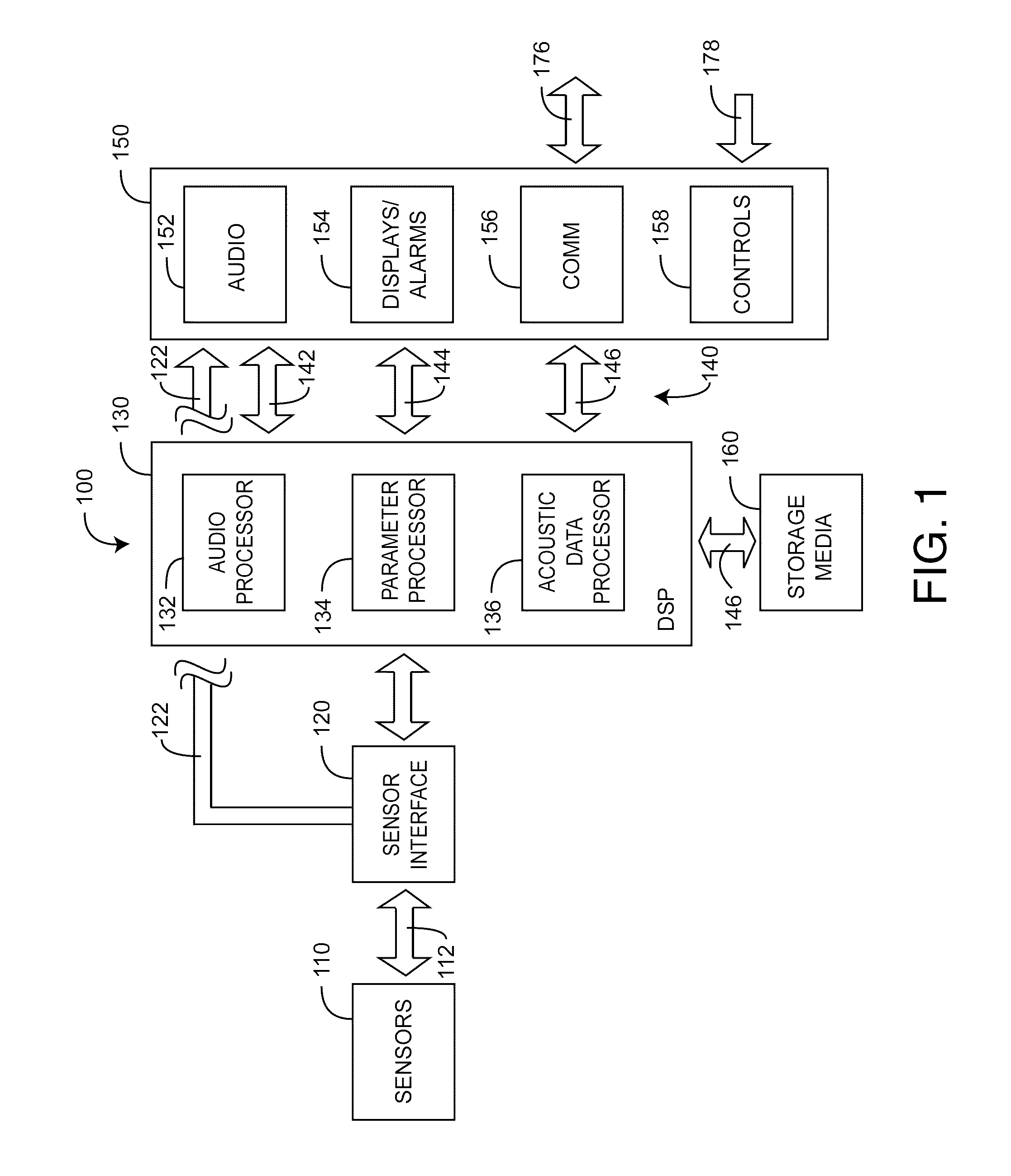
FIG. 1 generally illustrates a physiological acoustic monitoring system 100 embodiment having one or more sensors 110 in communications with one or more processors 130 via a sensor interface 120. The processors 130 both initiate and respond to input/output 150, including audio output 152, displays and alarms 154, communications 156 and controls 158. In an embodiment, the processors 130 are implemented in firmware executing on one or more digital signal processors (DSP), as described with respect to FIGS. 5-6, below. At least a portion of the sensors 110 generate acoustic signals, which may be directly utilized by the processors 130 or recorded onto or played back from storage media 160 or both.
The processors 130 include an audio processor 132 that outputs audio waveforms 142, a parameter processor 134 that derives physiological parameters 144 from sensor signals 112 and an acoustic data processor 136 that stores, retrieves and communicates acoustic data 146. Parameters include, as examples, respiration rate, heart rate and pulse rate. Audio waveforms include body sounds from the heart, lungs, gastrointestinal system and other organs. These body sounds may include tracheal air flow, heart beats and pulsatile blood flow, to name a few. Displays allow parameters 144 and acoustic data 146 to be visually presented to a user in various forms such as numbers, waveforms and graphs, as examples. Audio 152 allows audio waveforms to be reproduced through speakers, headphones or similar transducers. Raw audio 122 allows acoustic sensor signals 112 to be continuously reproduced through speakers, headphones or similar transducers, bypassing A/D conversion 120 and digital signal processing 130.
Storage media 160 allows acoustic data 146 to be recorded, organized, searched, retrieved and played back via the processors 130, communications 156 and audio output 152. Communications 156 transmit or receive acoustic data or audio waveforms via local area or wide area data networks or cellular networks 176. Controls 158 may cause the audio processor 132 to amplify, filter, shape or otherwise process audio waveforms 142 so as to emphasize, isolate, deemphasize or otherwise modify various features of an audio waveform or spectrum. In addition, controls 158 include buttons and switches 178, such as a "push to play" button that initiates local audio output 152 or remote transmission 176 of live or recorded acoustic waveforms.
As shown in FIG. 1, acoustic data 146 is initially derived from one or more acoustic sensor signals 112, along with, perhaps, other data inputs, such as from optical, blood pressure, EEG and ECG sensors, to name a few. The acoustic data 146 provides audio outputs 142, including audio respiration indicators, described with respect to FIGS. 8-9, below. The acoustic data 146, when analyzed, provides physiological parameters 144 that provide an indication of patient status, such as respiration rate or heart rate. Such analyses may result in visual or audible alerts or alarms 154 that are viewed locally or via notifications transmitted over local or wide area networks 176 to medical staff or other persons. Acoustic data 146 is utilized in real time or stored and retrieved for later use. Acoustic data 146 may be written on various storage media 160, such as a hard drive, and organized for convenient search and retrieval. In an embodiment, acoustic data 146 is advantageous organized on one or more hard drives as virtual magnetic tape so as to more easily manage, search, retrieve and playback acoustic data volumes. Further, the virtual tape volumes and/or the acoustic data itself may be entered into a database and organized as an acoustic library according to various search parameters including patient information, dates, corresponding physiological parameters and acoustic waveform features, to name a few. Applications for a physiological acoustic monitoring system include auscultation of body sounds by medical staff or by audio processors or both; SIDS monitoring; heart distress monitoring including the early detection and mitigation of myocardial infarction and cardiopulmonary arrest, as examples; and elder care, to name a few.
In an embodiment, sensor sounds 142 may be continuously "piped" to a remote device/listener or a central monitor or both. Listening devices may variously include pagers, cell phones, PDAs, electronic pads or tablets and laptops or other computers to name a few. Medical staff or other remote listeners are notified by the acoustic monitoring system according to flexible pre-programmed protocols to respond to the notification so as to hear breathing sounds, voice, heart sounds or other body sounds.
FIGS. 2A-B illustrate physiological acoustic monitoring system 200 embodiments each having dual channel acoustic sensors 201, 202 in communications with a physiological monitor 205. As shown in FIG. 2A, a first acoustic sensor 210 is utilized for deriving one or more physiological parameters, such as respiration rate. A second acoustic sensor 220 is utilized to continuously monitor body sounds. In an embodiment, the second acoustic sensor 220 has a different color or shape than the first acoustic sensor 210 so as identify the sensor as a body sound listening device rather than an acoustic sensing device for determining a physiological parameter. In an embodiment, the body sound sensor 220 is placed over the heart to allow the monitoring of heart sounds or for determination of heart rate. In an embodiment, the body sound sensor 220 generates a signal that bypasses monitor digitization and signal processing so as to allow continuous listening of the unprocessed or "raw" body sounds. In particular, the first acoustic sensor 210 is neck-mounted so as to determine one or more physiological parameters, such as respiration rate. The second acoustic sensor 220 is chest-mounted for monaural heart sound monitoring. As shown in FIG. 2B, first and second acoustic sensors 260, 270 are mounted proximate the same body site but with sufficient spatial separation to allow for stereo sensor reception. In this manner, the listener can more easily distinguish and identify the source of body sounds.
FIGS. 3A-B illustrate a body sound sensor 300 having acoustic 310, interconnect (not visible) and attachment 350 assemblies. The acoustic assembly 310 has an acoustic coupler 312 and a piezoelectric subassembly 314. The acoustic coupler 312 generally envelops or at least partially covers some or all of the piezoelectric subassembly 314. The piezoelectric subassembly 314 includes a piezoelectric membrane and a support frame (not visible). The piezoelectric membrane is configured to move on the frame in response to acoustic vibrations, thereby generating electrical signals indicative of body sounds. The acoustic coupler 312 advantageously improves the coupling between the acoustic signal measured at a skin site and the piezoelectric membrane. The acoustic coupler 312 includes a contact portion 316 placed against a person's skin.
Further shown in FIGS. 3A-B, the acoustic assembly 310 communicates with the sensor cable 340 via the interconnect assembly. In an embodiment, the interconnect assembly is a flex circuit having multiple conductors that are adhesively bonded to the attachment assembly 350. The interconnect assembly has a solder pad or other interconnect to interface with the sensor cable 340, and the attachment assembly 350 has a molded strain relief for the sensor cable. In an embodiment, the attachment assembly 350 is a generally circular, planar member having a top side 3511, a bottom side 352, and a center. A button 359 mechanically couples the acoustic assembly 310 to the attachment assembly center so that the acoustic assembly 310 extends from the bottom side 352. The sensor cable 340 extends from one end of the interconnect and attachment assemblies to a sensor connector at an opposite end so as to provide communications between the sensor and a monitor, as described in further detail with respect to, below. In an embodiment, an adhesive along the bottom side 352 secures the acoustic assembly 310 to a person's skin, such as at a neck, chest, back, abdomen site. A removable backing can be provided with the adhesive to protect the adhesive surface prior to affixing to a person's skin. In other embodiments, the attachment assembly 350 has a square, oval or oblong shape, so as to allow a uniform adhesion of the sensor to a measurement site. In a resposable embodiment, the attachment assembly 350 or portions thereof are removably detachable and attachable to the acoustic assembly 310 for disposal and replacement. The acoustic assembly 310 is reusable accordingly.
FIG. 4 illustrates sensor elements for a multi-acoustic sensor configuration, including a power interface 513, piezo circuits 410, 420 and a piezoelectric membrane 412, 422 corresponding to each sensor head e.g. 210, 220 (FIG. 2A). The piezoelectric membrane senses vibrations and generates a voltage in response to the vibrations, as described with respect to the sensor of FIGS. 3A-B, above. The signal generated by the piezoelectric membrane is communicated to the piezo circuit 410, 420, described immediately below, and transmits the signal to the monitor 205 (FIG. 2A) for signal conditioning and processing. The piezo circuit 410 decouples the power supply 513 and performs preliminary signal conditioning. In an embodiment, the piezo circuit 410 includes clamping diodes to provide electrostatic discharge (ESD) protection and a mid-level voltage DC offset for the piezoelectric signal to ride on, to be superimposed on or to be added to. The piezo circuit 410 may also have a high pass filter to eliminate unwanted low frequencies such as below about 100 Hz for breath sound applications, and an op amp to provide gain to the piezoelectric signal. The piezo circuit 410 may also have a low pass filter on the output of the op amp to filter out unwanted high frequencies. In an embodiment, a high pass filter is also provided on the output in addition to or instead of the low pass filter. The piezo circuit may also provide impedance compensation to the piezoelectric membrane, such as a series/parallel combination used to control the signal level strength and frequency of interest that is input to the op amp. In one embodiment, the impedance compensation is used to minimize the variation of the piezoelectric element output. The impedance compensation can be constructed of any combination of resistive, capacitive and inductive elements, such as RC or RLC circuits.
FIG. 5 illustrates a physiological acoustic monitor 500 for driving and processing signals from multi-acoustic sensor 401, 402 (FIG. 4). The monitor 500 includes one or more acoustic front-ends 521, 522, an analog-to-digital (A/D) converter 531, an audio driver 570 and a digital signal processor (DSP) 540. The DSP 540 can comprise a wide variety of data and/or signal processors capable of executing programs for determining physiological parameters from input data. In some embodiments, the monitor 500 also includes an optical front-end 525. In those embodiments, the monitor has an optical front-end 525, digital-to-analog (D/A) converters 534 and an A/D converter 535 to drive emitters and transform resulting composite analog intensity signal(s) from light sensitive detector(s) received via a sensor cable 510 into digital data input to the DSP 540. The acoustic front-ends 521, 522 and A/D converter 531 transform analog acoustic signals from a piezoelectric 410, 420 (FIG. 4) into digital data input to the DSP 540. The A/D converter 531 is shown as having a two-channel analog input and a multiplexed digital output to the DSP. In another embodiment, each front-end, communicates with a dedicated single channel A/D converter generating two independent digital outputs to the DSP. An acoustic front-end 521 can also feed an acoustic sensor signal 511 directly into an audio driver 570 for direct and continuous acoustic reproduction of the unprocessed sensor signal by a speaker, earphones or other audio transducer 562.
As shown in FIG. 5, the physiological acoustic monitor 500 may also have an instrument manager 550 that communicates between the DSP 540 and input/output 560. One or more I/O devices 560 have communications with the instrument manager 550 including displays, alarms, user I/O and instrument communication ports. Alarms 566 may be audible or visual indicators or both. The user I/O 568 may be, as examples, keypads, touch screens, pointing devices or voice recognition devices, to name a few. The displays 564 may be indicators, numerics or graphics for displaying one or more of various physiological parameters or acoustic data. The instrument manager 550 may also be capable of storing or displaying historical or trending data related to one or more of parameters or acoustic data.
As shown in FIG. 5, the physiological acoustic monitor 500 may also have a "push-to-talk" feature that provides a "listen on demand" capability. That is, a button 568 on the monitor is pushed or otherwise actuated so as to initiate acoustic sounds to be sent to a speaker, handheld device, or other listening device, either directly or via a network. The monitor 500 may also has a "mode selector" button or switch 568 that determines the acoustic content provided to a listener, either local or remote. These controls may be actuated local or at a distance by a remote listener. In an embodiment, push on demand audio occurs on an alarm condition in lieu of or in addition to an audio alarm. Controls 568 may include output filters like on a high quality stereo system so that a clinician or other user could selectively emphasize or deemphasize certain frequencies so as to hone-in on particular body sounds or characteristics.
In various embodiments, the monitor 500 may be one or more processor boards installed within and communicating with a host instrument. Generally, a processor board incorporates the front-end, drivers, converters and DSP. Accordingly, the processor board derives physiological parameters and communicates values for those parameters to the host instrument. Correspondingly, the host instrument incorporates the instrument manager and I/O devices. A processor board may also have one or more microcontrollers (not shown) for board management, including, for example, communications of calculated parameter data and the like to the host instrument.
Communications 569 may transmit or receive acoustic data or audio waveforms via local area or wide area data networks or cellular networks. Controls may cause the audio processor to amplify, filter, shape or otherwise process audio waveforms so as to emphasize, isolate, deemphasize or otherwise modify various features of the audio waveform or spectrum. In addition, switches, such as a "push to play" button can initiate audio output of live or recorded acoustic data. Controls may also initiate or direct communications.
FIG. 6 illustrates an acoustic physiological monitoring system 600 embodiment having a shared or open network architecture interconnecting one or more physiological monitors 610, monitoring stations 620 and mass storage 660. This interconnection includes proximity wireless devices 612 in direct wireless communication with a particular physiological monitor 610; local wireless devices 632 in communications with the monitors 610 via a wireless LAN 630; and distant wired or wireless devices 642, 652 in communications with the monitors 610 via WAN, such as Internet 640 or cellular networks 650. Communication devices may include local and remote monitoring stations 620 and wired or wireless communications and/or computing devices including cell phones, lap tops, pagers, PDAs, tablets and pads, to name a few. Physiological information is transmitted/received directly to/from end users over LAN or WAN. End users such as clinicians may carry wireless devices 632 in communications with the WLAN 630 so as to view in real-time physiological parameters or listen to audio data and waveforms on demand or in the event of an alarm or alert.
The network server 622 in certain embodiments provides logic and management tools to maintain connectivity between physiological monitors, clinician notification devices and external systems, such as EMRs. The network server 622 also provides a web based interface to allow installation (provisioning) of software related to the physiological monitoring system, adding new devices to the system, assigning notifiers to individual clinicians for alarm notification, escalation algorithms in cases where a primary caregiver does not respond to an alarm, interfaces to provide management reporting on alarm occurrences and internal journaling of system performance metrics such as overall system uptime. The network server 622 in certain embodiments also provides a platform for advanced rules engines and signal processing algorithms that provide early alerts in anticipation of a clinical alarm.
As shown in FIG. 6, audio data and corresponding audio files are advantageously stored on virtual tape 662, which provides the storage organization of tape cartridges without the slow, bulky, physical storage of magnetic tape and the corresponding human-operator intervention to physically locate and load physical cartridges into an actual tape-drive. A virtual tape controller 662 emulates standard tape cartridges and drives on modern, high capacity disk drive systems, as is well-known in the art. Accordingly, virtual "audio tapes" appear the same as physical tapes to applications, allowing the use of many existing cartridge tape storage, retrieval and archival applications. Further, while the upper-limit of a physical tape cartridge may be a few hundred megabytes, a virtual tape server 662 can be configured to provide considerably larger "tape" capacity. Mount-time is near-zero for a virtual tape and the data is available immediately. Also, while traditional physical tape systems have to read a tape from the beginning, moving sequentially through the files on the tape, a virtual drive can randomly access data at hard-disk speeds, providing tape I/O at disk access speeds.
Additionally shown in FIG. 6, a sound processing firmware module of certain embodiments accesses a database 670 of sound signatures 660 and compares the received signal with the entries in the database to characterize or identify sounds in the received signal. In another embodiment, the sound processing module generates and/or accesses a database 670 of sound signatures specific to a patient, or specific to a particular type of patient (e.g., male/female, pediatric/adult/geriatric, etc.). Samples from a person may be recorded and used to generate the sound signatures. In some embodiments, certain signal characteristics are used to identify particular sounds or classes of sounds. For example, in one embodiment, signal deviations of relatively high amplitude and or sharp slope may be identified by the sound processing module. Sounds identified in various embodiments by the sound processing module include, but are not limited to, breathing, speech, choking, swallowing, spasms such as larynx spasms, coughing, gasping, etc.
Once the sound processing module characterizes a particular type of sound, the acoustic monitoring system can, depending on the identified sound, use the characterization to generate an appropriate response. For example, the system may alert the appropriate medical personnel to modify treatment. In one embodiment, medical personnel may be alerted via an audio alarm, mobile phone call or text message, or other appropriate means. In one example scenario, the breathing of the patient can become stressed or the patient may begin to choke due to saliva, mucosal, or other build up around an endotracheal tube. In an embodiment, the sound processing module can identify the stressed breathing sounds indicative of such a situation and alert medical personnel to the situation so that a muscle relaxant medication can be given to alleviate the stressed breathing or choking.
According to some embodiments, acoustic sensors described herein can be used in a variety of other beneficial applications. For example, an auscultation firmware module may process a signal received by the acoustic sensor and provide an audio output indicative of internal body sounds of the patient, such as heart sounds, breathing sounds, gastrointestinal sounds, and the like. Medical personnel may listen to the audio output, such as by using a headset or speakers. In some embodiments the auscultation module allows medical personnel to remotely listen for patient diagnosis, communication, etc. For example, medical personnel may listen to the audio output in a different room in a hospital than the patient's room, in another building, etc. The audio output may be transmitted wirelessly (e.g., via Bluetooth, IEEE 802.11, over the Internet, etc.) in some embodiments such that medical personnel may listen to the audio output from generally any location.
FIGS. 7-8 illustrate alternative breath sound generators 701, 702 for providing an audio output for an acoustic sensor. As shown in FIG. 7A, acoustic sensor data is input to a processor board 701 so as to generate a corresponding breathing sound from a speaker or similar audio transducer. The audio data is A/D converted 710, down-sampled 720 and compressed 730. The monitor receives the compressed data 732, decompresses the data 740 and outputs the respiration audio 742 to a speaker. In an embodiment, the breath sound is combined with a pulse oximeter pulse "beep." However, unlike a pulse beep, this breath "beep" output may utilize nearly the full capacity of the processor board data channel 732.
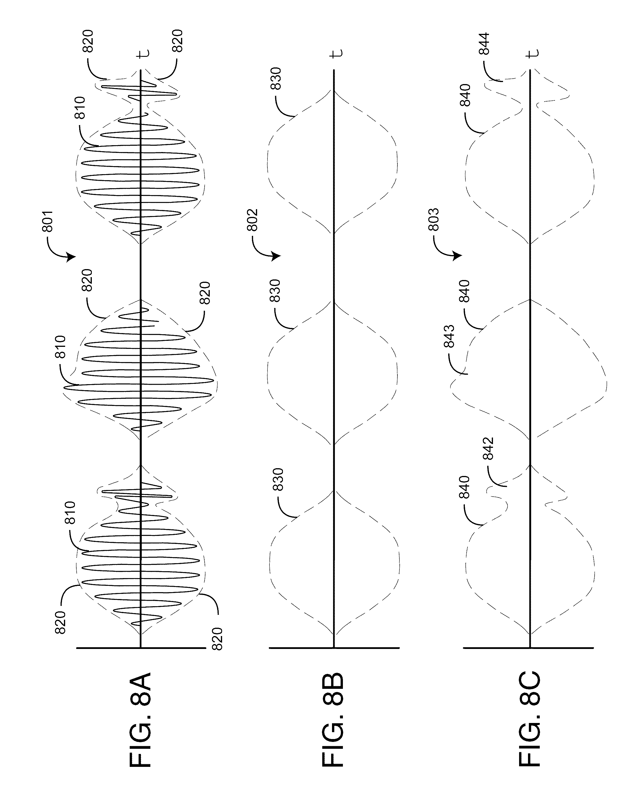
As shown in FIG. 7B and FIGS. 8A-C, an envelope-based breath sound generator advantageously provides breath sound reproduction at reduced data rates, which will not interfere with the data channel capacity of a signal processing board. Audio data is A/D converted 710 and input to an envelop detector 750. FIG. 8A illustrates a representative acoustic breath sound signal 810 derived by a neck sensor from tracheal air flow. The sound signal 810 has an envelope 820 with "pulses" corresponding to either inhalation or exhalation. The envelope detector 750 generates breath tags 760 describing the envelope 820. These breath tags 760 are transmitted to the monitor in lieu of the compressed audio signal described with respect to FIG. 7A, above. In one embodiment, the breath tags describe an idealized envelope 830, as shown in FIG. 8B. In another embodiment, the breath tags also include detected envelope features 842, 843, 844 that are characteristic of known acoustically-related phenomena such as wheezing or coughing, as examples. At the monitor end, envelop synthesis 770 reproduces the envelope 830 (FIG. 8B) and fills the envelope with an artificial waveform, such as white noise 780. This reconstructed or simulated breath signal is then output 782 to a speaker or similar device. In another embodiment, the breath tags are transmitted over a network to a remote device, which reconstructs the breathing waveform from the breath tags in like manner.
In various other embodiments, acoustic breathing waveforms are detected by an acoustic sensor, processed, transmitted and played on a local or remote speaker or other audio output from actual (raw) data, synthetic data and artificial data. Actual data may be compressed, but is a nearly complete or totally complete reproduction of the actual acoustic sounds at the sensor. Synthetic data may be a synthetic version of the breathing sound with the option of the remote listener to request additional resolution. Artificial data may simulate an acoustic sensor sound with minimal data rate or bandwidth, but is not as clinically useful as synthetic or actual data. Artificial data may, for example, be white noise bursts generated in sync with sensed respiration. Synthetic data is something between actual data and artificial data, such as the acoustic envelope process described above that incorporates some information from the actual sensor signal. In an embodiment breath sounds are artificially hi/lo frequency shifted or hi/lo volume amplified to distinguish inhalation/exhalation. In an embodiment, dual acoustic sensors placed along the neck are responsive to the relative time of arrival of tracheal sounds so as to distinguish inhalation and exhalation in order to appropriately generate the hi/lo frequency shifts.
FIG. 9 illustrates a physiological acoustic monitor 900 for out-patient applications, including sudden infant death syndrome (SIDS) prevention and elder care. The monitor 900 has a sensor section 901 and a remote section 902. The sensor section 901 has a sensor 910, a sensor interface 920 and a communications element 930. In an embodiment, the sensor 910 is an adhesive substrate integrated with a piezoelectric assembly and interconnect cable, such as described with respect to FIGS. 3A-B, above. The sensor interface 920 provides power to and receives the sensor signal from the sensor piezo circuit, as described with respect to FIGS. 4-5, above. The wireless communications element 930 receives the sensor signal from the sensor interface and transmits the signal to the corresponding communications element 940 in the remote section 902, which provides an amplified sensor signal sufficient to drive a small speaker. In an embodiment, the communications link 960 conforms with IEEE 802.15 (Bluetooth).
A physiological acoustic monitoring system has been disclosed in detail in connection with various embodiments. These embodiments are disclosed by way of examples only and are not to limit the scope of the claims that follow. One of ordinary skill in art will appreciate many variations and modifications.
* * * * *
D00000
D00001
D00002
D00003
D00004
D00005
D00006
D00007
D00008
D00009
XML
uspto.report is an independent third-party trademark research tool that is not affiliated, endorsed, or sponsored by the United States Patent and Trademark Office (USPTO) or any other governmental organization. The information provided by uspto.report is based on publicly available data at the time of writing and is intended for informational purposes only.
While we strive to provide accurate and up-to-date information, we do not guarantee the accuracy, completeness, reliability, or suitability of the information displayed on this site. The use of this site is at your own risk. Any reliance you place on such information is therefore strictly at your own risk.
All official trademark data, including owner information, should be verified by visiting the official USPTO website at www.uspto.gov. This site is not intended to replace professional legal advice and should not be used as a substitute for consulting with a legal professional who is knowledgeable about trademark law.