Multilayer disk drive motors having out-of-plane bending
Bjorstrom , et al.
U.S. patent number 10,339,966 [Application Number 15/811,504] was granted by the patent office on 2019-07-02 for multilayer disk drive motors having out-of-plane bending. This patent grant is currently assigned to Hutchinson Technology Incorporated. The grantee listed for this patent is Hutchinson Technology Incorporated. Invention is credited to Jacob D. Bjorstrom, Ryan N. Ruzicka, Joseph C. Wheatley.


View All Diagrams
| United States Patent | 10,339,966 |
| Bjorstrom , et al. | July 2, 2019 |
Multilayer disk drive motors having out-of-plane bending
Abstract
Various embodiments concern a gimbaled flexure having a dual stage actuation structure. The flexure comprises a gimbal on which a motor is mounted. The motor comprises a first and second terminals and a plurality of actuator layers formed from a piezoelectric material. The plurality of actuator layers comprise serially stacked first, second, and third actuator layers. The plurality of actuator layers are respectively poled and connected to the first and second terminals such that both of the first and second actuator layers expand while the third actuator layer contracts in response to application of a signal across the first and second terminals. The differential motion of the plurality of layers in the motor cause the motor to curl about the contracting third actuator layer. The curling motion causes a portion of the flexure to preferentially curl.
| Inventors: | Bjorstrom; Jacob D. (Hutchinson, MN), Ruzicka; Ryan N. (Waconia, MN), Wheatley; Joseph C. (Hutchinson, MN) | ||||||||||
|---|---|---|---|---|---|---|---|---|---|---|---|
| Applicant: |
|
||||||||||
| Assignee: | Hutchinson Technology
Incorporated (Hutchinson, MN) |
||||||||||
| Family ID: | 55700083 | ||||||||||
| Appl. No.: | 15/811,504 | ||||||||||
| Filed: | November 13, 2017 |
Prior Publication Data
| Document Identifier | Publication Date | |
|---|---|---|
| US 20180068683 A1 | Mar 8, 2018 | |
Related U.S. Patent Documents
| Application Number | Filing Date | Patent Number | Issue Date | ||
|---|---|---|---|---|---|
| 15398144 | Jan 4, 2017 | 9818437 | |||
| 15071762 | Feb 7, 2017 | 9564154 | |||
| 14579063 | Apr 19, 2016 | 9318136 | |||
| Current U.S. Class: | 1/1 |
| Current CPC Class: | G11B 5/4833 (20130101); G11B 5/4873 (20130101); G11B 5/4853 (20130101); G11B 5/483 (20150901); G11B 5/5552 (20130101); G11B 5/4826 (20130101) |
| Current International Class: | G11B 5/48 (20060101); G11B 5/55 (20060101) |
| Field of Search: | ;360/245,245.3,245.6,264.3,264.4,264.5,294.3,294.4 |
References Cited [Referenced By]
U.S. Patent Documents
| 3320556 | May 1967 | Schneider |
| 3582575 | June 1971 | Scofield |
| 3862522 | January 1975 | Mednick |
| 3877120 | April 1975 | Hikota et al. |
| 3910339 | October 1975 | Kramer |
| 4014257 | March 1977 | Bettenhausen |
| 4168214 | September 1979 | Fletcher et al. |
| 4181554 | January 1980 | Rich |
| 4299130 | November 1981 | Koneval |
| 4418239 | November 1983 | Larson et al. |
| 4422906 | December 1983 | Kobayashi |
| 4659438 | April 1987 | Kuhn et al. |
| 4916798 | April 1990 | Ballast |
| 5140288 | August 1992 | Grunwell |
| 5189779 | March 1993 | Fishel et al. |
| 5212847 | May 1993 | Melcher et al. |
| 5275076 | January 1994 | Greenwalt |
| 5320272 | June 1994 | Melton et al. |
| 5321568 | June 1994 | Hatam-Tabrizi |
| 5333085 | July 1994 | Prentice et al. |
| 5427848 | June 1995 | Baer et al. |
| 5459921 | October 1995 | Hudson et al. |
| 5485053 | January 1996 | Baz |
| 5491597 | February 1996 | Bennin et al. |
| 5521778 | May 1996 | Boutaghou et al. |
| 5526208 | June 1996 | Hatch et al. |
| 5598307 | January 1997 | Bennin |
| 5608590 | March 1997 | Ziegler et al. |
| 5608591 | March 1997 | Klaassen et al. |
| 5631786 | May 1997 | Erpelding |
| 5636089 | June 1997 | Jurgenson et al. |
| 5651723 | July 1997 | Bjornard et al. |
| 5657186 | August 1997 | Kudo et al. |
| 5657188 | August 1997 | Jurgenson et al. |
| 5666241 | September 1997 | Summers |
| 5666717 | September 1997 | Matsumoto et al. |
| 5694270 | December 1997 | Sone et al. |
| 5712749 | January 1998 | Gustafson |
| 5714444 | February 1998 | Yokouchi et al. |
| 5717547 | February 1998 | Young |
| 5722142 | March 1998 | Myers |
| 5734526 | March 1998 | Symons |
| 5737152 | April 1998 | Balakrishnan |
| 5754368 | May 1998 | Shiraishi et al. |
| 5764444 | June 1998 | Imamura et al. |
| 5773889 | June 1998 | Love et al. |
| 5790347 | August 1998 | Girard |
| 5795435 | August 1998 | Waters et al. |
| 5796552 | August 1998 | Akin, Jr. et al. |
| 5805382 | September 1998 | Lee et al. |
| 5812344 | September 1998 | Balakrishnan |
| 5818662 | October 1998 | Shum |
| 5857257 | January 1999 | Inaba |
| 5862010 | January 1999 | Simmons et al. |
| 5862015 | January 1999 | Evans et al. |
| 5889137 | March 1999 | Hutchings et al. |
| 5892637 | April 1999 | Brooks, Jr. et al. |
| 5893201 | April 1999 | Myers |
| 5898541 | April 1999 | Boutaghou |
| 5898544 | April 1999 | Krinke et al. |
| 5914834 | June 1999 | Gustafson |
| 5921131 | July 1999 | Stange |
| 5922000 | July 1999 | Chodorow |
| 5924187 | July 1999 | Matz |
| 5929390 | July 1999 | Naito et al. |
| 5956212 | September 1999 | Zhu |
| 5973882 | October 1999 | Tangren |
| 5973884 | October 1999 | Hagen |
| 5986853 | November 1999 | Simmons et al. |
| 5995328 | November 1999 | Balakrishnan |
| 5995329 | November 1999 | Shiraishi et al. |
| 6011671 | January 2000 | Masse et al. |
| 6029334 | February 2000 | Hartley |
| 6038102 | March 2000 | Balakrishnan et al. |
| 6046887 | April 2000 | Uozumi et al. |
| 6055132 | April 2000 | Arya et al. |
| 6063228 | May 2000 | Sasaki et al. |
| 6075676 | June 2000 | Hiraoka et al. |
| 6078470 | June 2000 | Danielson et al. |
| 6085456 | July 2000 | Battaglia |
| 6095023 | August 2000 | Harada et al. |
| 6108175 | August 2000 | Hawwa et al. |
| 6115221 | September 2000 | Utsunomiya |
| 6118637 | September 2000 | Wright |
| 6144531 | November 2000 | Sawai |
| 6146813 | November 2000 | Girard et al. |
| 6156982 | December 2000 | Dawson |
| 6157522 | December 2000 | Murphy et al. |
| 6172853 | January 2001 | Davis et al. |
| 6181520 | January 2001 | Fukuda |
| 6195227 | February 2001 | Fan et al. |
| 6215622 | April 2001 | Ruiz et al. |
| 6215629 | April 2001 | Kant et al. |
| 6229673 | May 2001 | Shinohara et al. |
| 6233124 | May 2001 | Budde et al. |
| 6239953 | May 2001 | Mei |
| 6246546 | June 2001 | Tangren |
| 6246552 | June 2001 | Soeno |
| 6249404 | June 2001 | Doundakov et al. |
| 6262868 | July 2001 | Arya et al. |
| 6275358 | August 2001 | Balakrishnan et al. |
| 6278587 | August 2001 | Mei |
| 6282062 | August 2001 | Shiraishi |
| 6289564 | September 2001 | Novotny |
| 6295185 | September 2001 | Stefansky |
| 6297936 | October 2001 | Kant |
| 6300846 | October 2001 | Brunker |
| 6307715 | October 2001 | Berding et al. |
| 6308483 | October 2001 | Romine |
| 6320730 | November 2001 | Stefansky et al. |
| 6330132 | December 2001 | Honda |
| 6349017 | February 2002 | Schott |
| 6366431 | April 2002 | Tsuchiya et al. |
| 6376964 | April 2002 | Young |
| 6380483 | April 2002 | Blake |
| 6381821 | May 2002 | Panyon et al. |
| 6387111 | May 2002 | Barber |
| 6396667 | May 2002 | Zhang et al. |
| 6399899 | June 2002 | Ohkawa et al. |
| 6400532 | June 2002 | Mei |
| 6404594 | June 2002 | Maruyama et al. |
| 6407481 | June 2002 | Takeuchi et al. |
| 6424500 | July 2002 | Coon et al. |
| 6445546 | September 2002 | Coon |
| 6459549 | October 2002 | Tsuchiya et al. |
| 6480359 | November 2002 | Dunn et al. |
| 6487045 | November 2002 | Yanagisawa |
| 6490228 | December 2002 | Killam |
| 6493190 | December 2002 | Coon |
| 6493192 | December 2002 | Crane et al. |
| 6498704 | December 2002 | Chessman et al. |
| 6501625 | December 2002 | Boismier |
| 6539609 | April 2003 | Palmer et al. |
| 6549376 | April 2003 | Scura et al. |
| 6549736 | April 2003 | Miyabe et al. |
| 6563676 | May 2003 | Chew et al. |
| 6581262 | June 2003 | Myers |
| 6596184 | July 2003 | Shum et al. |
| 6597541 | July 2003 | Nishida et al. |
| 6600631 | July 2003 | Berding et al. |
| 6621653 | September 2003 | Schirle |
| 6621658 | September 2003 | Nashif |
| 6636388 | October 2003 | Stefansaky |
| 6639761 | October 2003 | Boutaghou et al. |
| 6647621 | November 2003 | Roen et al. |
| 6653763 | November 2003 | Wang |
| 6661617 | December 2003 | Hipwell, Jr. et al. |
| 6661618 | December 2003 | Fujiwara et al. |
| 6704157 | March 2004 | Himes et al. |
| 6704158 | March 2004 | Hawwa et al. |
| 6704165 | March 2004 | Kube et al. |
| 6711930 | March 2004 | Thom et al. |
| 6714384 | March 2004 | Himes et al. |
| 6714385 | March 2004 | Even et al. |
| 6724580 | April 2004 | Irie |
| 6728057 | April 2004 | Putnam |
| 6728077 | April 2004 | Murphy |
| 6731472 | May 2004 | Okamoto et al. |
| 6735052 | May 2004 | Dunn et al. |
| 6735055 | May 2004 | Crane et al. |
| 6737931 | May 2004 | Amparan et al. |
| 6738225 | May 2004 | Summers et al. |
| 6741424 | May 2004 | Danielson et al. |
| 6751062 | June 2004 | Kasajima et al. |
| 6752661 | June 2004 | Gu et al. |
| 6760182 | July 2004 | Bement et al. |
| 6760194 | July 2004 | Shiraishi et al. |
| 6760196 | July 2004 | Niu et al. |
| 6762913 | July 2004 | Even et al. |
| 6765761 | July 2004 | Arya |
| 6771466 | August 2004 | Kasajima et al. |
| 6771467 | August 2004 | Kasajima et al. |
| 6789593 | September 2004 | Aono et al. |
| 6791802 | September 2004 | Watanabe et al. |
| 6796018 | September 2004 | Thonton |
| 6797888 | September 2004 | Ookawa et al. |
| 6798597 | September 2004 | Aram et al. |
| 6801402 | October 2004 | Subrahmanyam et al. |
| 6802496 | October 2004 | Preta |
| 6831539 | December 2004 | Hipwell, Jr. et al. |
| 6833978 | December 2004 | Shum et al. |
| 6839204 | January 2005 | Shiraishi et al. |
| 6841737 | January 2005 | Komatsubara et al. |
| 6856075 | February 2005 | Houk et al. |
| 6859345 | February 2005 | Boutaghou |
| 6870091 | March 2005 | Seidler |
| 6882506 | April 2005 | Yamaoka et al. |
| 6891700 | May 2005 | Shiraishi et al. |
| 6898042 | May 2005 | Subrahmanyan |
| 6900967 | May 2005 | Coon et al. |
| 6922305 | July 2005 | Price |
| 6934127 | August 2005 | Yao et al. |
| 6942817 | September 2005 | Yagi et al. |
| 6943991 | September 2005 | Yao et al. |
| 6950288 | September 2005 | Yao et al. |
| 6961221 | November 2005 | Niu |
| 6963471 | November 2005 | Arai et al. |
| 6975488 | December 2005 | Kulangara et al. |
| 6977790 | December 2005 | Chen et al. |
| 7006333 | February 2006 | Summers |
| 7016159 | March 2006 | Bjorstrom et al. |
| 7020949 | April 2006 | Muramatsu et al. |
| 7023667 | April 2006 | Shum |
| 7050267 | May 2006 | Koh et al. |
| 7057857 | June 2006 | Niu et al. |
| 7064928 | June 2006 | Fu et al. |
| 7068473 | June 2006 | O'Neill |
| 7079357 | July 2006 | Kulangara et al. |
| 7082670 | August 2006 | Boismier et al. |
| 7092215 | August 2006 | Someya et al. |
| 7099115 | August 2006 | Yao |
| 7099117 | August 2006 | Subrahmanyam et al. |
| 7129418 | October 2006 | Aonuma et al. |
| 7130159 | October 2006 | Shimizu et al. |
| 7132607 | November 2006 | Yoshimi et al. |
| 7142395 | November 2006 | Swanson et al. |
| 7144687 | December 2006 | Fujisaki et al. |
| 7158348 | January 2007 | Erpelding et al. |
| 7159300 | January 2007 | Yao et al. |
| 7161765 | January 2007 | Ichikawa et al. |
| 7161767 | January 2007 | Hernandez et al. |
| 7177119 | February 2007 | Bennin et al. |
| 7185409 | March 2007 | Myers |
| 7218481 | May 2007 | Bennin et al. |
| 7256968 | August 2007 | Krinke |
| 7271958 | September 2007 | Yoon et al. |
| 7283331 | October 2007 | Oh et al. |
| 7288590 | October 2007 | Lechat et al. |
| 7292413 | November 2007 | Coon |
| 7307817 | December 2007 | Mei |
| 7322241 | January 2008 | Kai |
| 7336436 | February 2008 | Sharma et al. |
| 7336444 | February 2008 | Kido et al. |
| 7338693 | March 2008 | Shikano et al. |
| 7342750 | March 2008 | Yang et al. |
| 7345851 | March 2008 | Hirano et al. |
| 7375930 | May 2008 | Yang |
| 7379274 | May 2008 | Yao et al. |
| 7382582 | June 2008 | Cuevas |
| 7384531 | June 2008 | Peltoma et al. |
| 7385788 | June 2008 | Kubota et al. |
| 7388733 | June 2008 | Swanson et al. |
| 7391594 | June 2008 | Fu et al. |
| 7403357 | July 2008 | Williams |
| 7408745 | August 2008 | Yao et al. |
| 7417830 | August 2008 | Kulangara |
| 7420778 | September 2008 | Sassine et al. |
| 7459835 | December 2008 | Mei |
| 7460337 | December 2008 | Mei |
| 7466520 | December 2008 | White et al. |
| 7499246 | March 2009 | Nakagawa |
| 7509859 | March 2009 | Kai |
| 7518830 | April 2009 | Panchal et al. |
| 7567410 | July 2009 | Zhang et al. |
| 7595965 | September 2009 | Kulangara et al. |
| RE40975 | November 2009 | Evans et al. |
| 7625654 | December 2009 | Vyas et al. |
| 7629539 | December 2009 | Ishii et al. |
| 7636222 | December 2009 | Dobosz et al. |
| 7643252 | January 2010 | Arai et al. |
| 7649254 | January 2010 | Graydon et al. |
| 7663841 | February 2010 | Budde et al. |
| 7667921 | February 2010 | Satoh et al. |
| 7675713 | March 2010 | Ogawa et al. |
| 7688552 | March 2010 | Yao et al. |
| 7692899 | April 2010 | Arai et al. |
| 7697237 | April 2010 | Danielson |
| 7701673 | April 2010 | Wang et al. |
| 7701674 | April 2010 | Arai |
| 7710687 | May 2010 | Carlson et al. |
| 7710688 | May 2010 | Hentges et al. |
| 7719798 | May 2010 | Yao |
| 7724476 | May 2010 | Bjorstrom et al. |
| 7724478 | May 2010 | Deguchi et al. |
| 7751153 | July 2010 | Kulangara et al. |
| 7768746 | August 2010 | Yao et al. |
| 7782572 | August 2010 | Pro |
| 7804663 | September 2010 | Hirano et al. |
| 7813083 | October 2010 | Guo et al. |
| 7813084 | October 2010 | Hentges |
| 7821742 | October 2010 | Mei |
| 7826177 | November 2010 | Zhang et al. |
| 7832082 | November 2010 | Hentges et al. |
| 7835113 | November 2010 | Douglas |
| 7872344 | January 2011 | Fjelstad et al. |
| 7875804 | January 2011 | Tronnes et al. |
| 7902639 | March 2011 | Garrou et al. |
| 7914926 | March 2011 | Kimura et al. |
| 7923644 | April 2011 | Ishii et al. |
| 7924530 | April 2011 | Chocholaty |
| 7929252 | April 2011 | Hentges et al. |
| 7946010 | May 2011 | Myers et al. |
| 7983008 | July 2011 | Liao et al. |
| 7986494 | July 2011 | Pro |
| 8004798 | August 2011 | Dunn |
| 8072708 | December 2011 | Horiuchi |
| 8085508 | December 2011 | Hatch |
| 8089728 | January 2012 | Yao et al. |
| 8120878 | February 2012 | Drape et al. |
| 8125736 | February 2012 | Nojima et al. |
| 8125741 | February 2012 | Shelor |
| 8144430 | March 2012 | Hentges et al. |
| 8144436 | March 2012 | Iriuchijima et al. |
| 8149542 | April 2012 | Ando et al. |
| 8149545 | April 2012 | Chai |
| 8151440 | April 2012 | Tsutsumi et al. |
| 8154827 | April 2012 | Contreras et al. |
| 8157947 | April 2012 | Kim |
| 8161626 | April 2012 | Ikeji |
| 8169746 | May 2012 | Rice et al. |
| 8174797 | May 2012 | Iriuchijima |
| 8189281 | May 2012 | Alex et al. |
| 8189301 | May 2012 | Schreiber |
| 8194359 | June 2012 | Yao et al. |
| 8199441 | June 2012 | Nojima |
| 8199442 | June 2012 | Okawara et al. |
| 8228642 | July 2012 | Hahn et al. |
| 8233240 | July 2012 | Contreras et al. |
| 8248731 | August 2012 | Fuchino |
| 8248734 | August 2012 | Fuchino |
| 8248735 | August 2012 | Fujimoto et al. |
| 8248736 | August 2012 | Hanya et al. |
| 8254062 | August 2012 | Greminger |
| 8259416 | September 2012 | Davis et al. |
| 8264797 | September 2012 | Emley |
| 8284524 | October 2012 | Meyer |
| 8289652 | October 2012 | Zambri et al. |
| 8289656 | October 2012 | Huber |
| 8295012 | October 2012 | Tian et al. |
| 8296929 | October 2012 | Hentges et al. |
| 8300362 | October 2012 | Virmani et al. |
| 8300363 | October 2012 | Arai et al. |
| 8305712 | November 2012 | Contreras et al. |
| 8310790 | November 2012 | Fanslau, Jr. |
| 8331061 | December 2012 | Hanya et al. |
| 8339748 | December 2012 | Shum et al. |
| 8351160 | January 2013 | Fujimoto |
| 8363361 | January 2013 | Hanya et al. |
| 8369046 | February 2013 | Nojima |
| 8379349 | February 2013 | Pro et al. |
| 8405933 | March 2013 | Soga |
| 8405934 | March 2013 | Fuchino |
| 8446694 | May 2013 | Tian |
| 8456780 | June 2013 | Ruiz |
| 8498082 | July 2013 | Padeski et al. |
| 8503133 | August 2013 | Arai et al. |
| 8508888 | August 2013 | Ohsawa |
| 8526142 | September 2013 | Dejkoonmak et al. |
| 8542465 | September 2013 | Liu et al. |
| 8553364 | October 2013 | Schreiber et al. |
| 8559137 | October 2013 | Imuta |
| 8582243 | November 2013 | Feng et al. |
| 8593764 | November 2013 | Tian |
| 8630067 | January 2014 | Ando et al. |
| 8634166 | January 2014 | Ohnuki et al. |
| 8665565 | March 2014 | Pro et al. |
| 8665567 | March 2014 | Shum et al. |
| 8675314 | March 2014 | Bjorstrom |
| 8681456 | March 2014 | Miller et al. |
| 8717712 | May 2014 | Bennin et al. |
| 8741195 | June 2014 | Kurihara et al. |
| 8780503 | July 2014 | Wright et al. |
| 8792214 | July 2014 | Bjorstrom et al. |
| 8834660 | September 2014 | Scheele et al. |
| 8885297 | November 2014 | Bjorstrom et al. |
| 8891206 | November 2014 | Miller |
| 8896968 | November 2014 | Miller et al. |
| 8896969 | November 2014 | Miller et al. |
| 8896970 | November 2014 | Miller et al. |
| 9007726 | April 2015 | Bennin et al. |
| 9036302 | May 2015 | Bjorstrom et al. |
| 9070392 | June 2015 | Bjorstrom |
| 9093117 | July 2015 | Tobias |
| 9117468 | August 2015 | Zhang et al. |
| 9147413 | September 2015 | Miller et al. |
| 9240203 | January 2016 | Miller et al. |
| 9245555 | January 2016 | Bennin et al. |
| 9257139 | February 2016 | Miller |
| 9296188 | March 2016 | Cray et al. |
| 9318136 | April 2016 | Bjorstrom |
| 9330697 | May 2016 | Miller et al. |
| 9564154 | February 2017 | Bjorstrom |
| 9818437 | November 2017 | Bjorstrom |
| 2001/0001937 | May 2001 | Benes et al. |
| 2001/0012181 | August 2001 | Inoue et al. |
| 2001/0013993 | August 2001 | Coon |
| 2001/0030838 | October 2001 | Takadera et al. |
| 2001/0043443 | November 2001 | Okamoto et al. |
| 2002/0012194 | January 2002 | Inagaki et al. |
| 2002/0075606 | June 2002 | Nishida et al. |
| 2002/0118492 | August 2002 | Watanabe et al. |
| 2002/0149888 | October 2002 | Motonishi et al. |
| 2002/0159845 | October 2002 | Mikell |
| 2002/0168897 | November 2002 | Chang |
| 2002/0176209 | November 2002 | Schulz et al. |
| 2002/0178778 | December 2002 | Thom et al. |
| 2003/0011118 | January 2003 | Kasajima et al. |
| 2003/0011936 | January 2003 | Himes et al. |
| 2003/0051890 | March 2003 | Marshall |
| 2003/0053258 | March 2003 | Dunn et al. |
| 2003/0089520 | May 2003 | Ooyabu et al. |
| 2003/0135985 | July 2003 | Yao et al. |
| 2003/0174445 | September 2003 | Luo |
| 2003/0202293 | October 2003 | Nakamura et al. |
| 2003/0210499 | November 2003 | Arya |
| 2004/0007322 | January 2004 | Lechat et al. |
| 2004/0008449 | January 2004 | Girard |
| 2004/0027727 | February 2004 | Shimizu et al. |
| 2004/0027728 | February 2004 | Coffey et al. |
| 2004/0032093 | February 2004 | Razavi |
| 2004/0070884 | April 2004 | Someya et al. |
| 2004/0084198 | May 2004 | Seidler |
| 2004/0125508 | July 2004 | Yang et al. |
| 2004/0181932 | September 2004 | Yao et al. |
| 2004/0207957 | October 2004 | Kasajima et al. |
| 2004/0221447 | November 2004 | Ishii et al. |
| 2004/0250952 | December 2004 | Lechat et al. |
| 2004/0264056 | December 2004 | Jang et al. |
| 2005/0045914 | March 2005 | Agranat et al. |
| 2005/0060864 | March 2005 | Nikolaidis et al. |
| 2005/0061542 | March 2005 | Aonuma et al. |
| 2005/0063097 | March 2005 | Maruyama et al. |
| 2005/0101983 | May 2005 | Loshakove et al. |
| 2005/0105217 | May 2005 | Kwon et al. |
| 2005/0117257 | June 2005 | Thaveeprungsriporn et al. |
| 2005/0180053 | August 2005 | Dovek et al. |
| 2005/0254175 | November 2005 | Swanson et al. |
| 2005/0280944 | December 2005 | Yang et al. |
| 2006/0044698 | March 2006 | Hirano et al. |
| 2006/0077594 | April 2006 | White et al. |
| 2006/0181812 | August 2006 | Kwon et al. |
| 2006/0193086 | August 2006 | Zhu et al. |
| 2006/0209465 | September 2006 | Takikawa et al. |
| 2006/0238924 | October 2006 | Gatzen |
| 2006/0248702 | November 2006 | Nikolaidis et al. |
| 2006/0274452 | December 2006 | Arya |
| 2006/0274453 | December 2006 | Arya |
| 2006/0279880 | December 2006 | Boutaghou et al. |
| 2007/0005072 | January 2007 | Castillo et al. |
| 2007/0041123 | February 2007 | Swanson et al. |
| 2007/0133128 | June 2007 | Arai |
| 2007/0153430 | July 2007 | Park et al. |
| 2007/0223146 | September 2007 | Yao et al. |
| 2007/0227769 | October 2007 | Brodsky et al. |
| 2007/0253176 | November 2007 | Ishii et al. |
| 2008/0024928 | January 2008 | Yang |
| 2008/0024933 | January 2008 | Yao et al. |
| 2008/0071302 | March 2008 | Castillo et al. |
| 2008/0084638 | April 2008 | Bonin |
| 2008/0124842 | May 2008 | Wang et al. |
| 2008/0144225 | June 2008 | Yao et al. |
| 2008/0192384 | August 2008 | Danielson et al. |
| 2008/0198511 | August 2008 | Hirano et al. |
| 2008/0229842 | September 2008 | Ohtsuka et al. |
| 2008/0247131 | October 2008 | Hitomi et al. |
| 2008/0251201 | October 2008 | Sikkel et al. |
| 2008/0264557 | October 2008 | Kim |
| 2008/0272122 | November 2008 | Son |
| 2008/0273266 | November 2008 | Pro |
| 2008/0273269 | November 2008 | Pro |
| 2009/0027807 | January 2009 | Yao et al. |
| 2009/0080117 | March 2009 | Shimizu et al. |
| 2009/0135523 | May 2009 | Nishiyama et al. |
| 2009/0147407 | June 2009 | Huang et al. |
| 2009/0168249 | July 2009 | McCaslin et al. |
| 2009/0176120 | July 2009 | Wang |
| 2009/0183359 | July 2009 | Tsutsumi et al. |
| 2009/0190263 | July 2009 | Miura et al. |
| 2009/0244786 | October 2009 | Hatch |
| 2009/0284870 | November 2009 | Nojima |
| 2009/0294740 | December 2009 | Kurtz et al. |
| 2010/0007993 | January 2010 | Contreras et al. |
| 2010/0067151 | March 2010 | Okaware et al. |
| 2010/0073825 | March 2010 | Okawara |
| 2010/0097726 | April 2010 | Greminger et al. |
| 2010/0142081 | June 2010 | Funabashi et al. |
| 2010/0143743 | June 2010 | Yamasaki et al. |
| 2010/0165515 | July 2010 | Ando |
| 2010/0165516 | July 2010 | Fuchino |
| 2010/0177445 | July 2010 | Fuchino |
| 2010/0195251 | August 2010 | Nojima et al. |
| 2010/0195252 | August 2010 | Kashima |
| 2010/0208390 | August 2010 | Hanya et al. |
| 2010/0208425 | August 2010 | Rapisarda |
| 2010/0220414 | September 2010 | Klarqvist et al. |
| 2010/0246071 | September 2010 | Nojima |
| 2010/0271735 | October 2010 | Schreiber |
| 2010/0277834 | November 2010 | Nojima |
| 2010/0290158 | November 2010 | Hanya et al. |
| 2011/0013319 | January 2011 | Soga et al. |
| 2011/0058281 | March 2011 | Arai et al. |
| 2011/0058282 | March 2011 | Fujimoto et al. |
| 2011/0096438 | April 2011 | Takada et al. |
| 2011/0096440 | April 2011 | Greminger |
| 2011/0123145 | May 2011 | Nishio |
| 2011/0141624 | June 2011 | Fuchino et al. |
| 2011/0141626 | June 2011 | Contreras et al. |
| 2011/0159767 | June 2011 | Sakurai et al. |
| 2011/0228425 | September 2011 | Liu et al. |
| 2011/0242708 | October 2011 | Fuchino |
| 2011/0279929 | November 2011 | Kin |
| 2011/0299197 | December 2011 | Eguchi |
| 2011/0299288 | December 2011 | Rapisarda |
| 2012/0000376 | January 2012 | Kurihara et al. |
| 2012/0002329 | January 2012 | Shum et al. |
| 2012/0081813 | April 2012 | Ezawa et al. |
| 2012/0081815 | April 2012 | Arai et al. |
| 2012/0087041 | April 2012 | Ohsawa |
| 2012/0099226 | April 2012 | Zambri et al. |
| 2012/0113547 | May 2012 | Sugimoto |
| 2012/0180956 | July 2012 | Kim |
| 2012/0248759 | October 2012 | Feith |
| 2012/0276232 | November 2012 | Marczyk et al. |
| 2012/0279757 | November 2012 | Ishii et al. |
| 2012/0281316 | November 2012 | Fujimoto et al. |
| 2012/0285306 | November 2012 | Weibelt |
| 2013/0020112 | January 2013 | Ohsawa |
| 2013/0021698 | January 2013 | Greminger et al. |
| 2013/0047807 | February 2013 | Sotokawa et al. |
| 2013/0055561 | March 2013 | Tsutsumi et al. |
| 2013/0107488 | May 2013 | Arai |
| 2013/0176646 | July 2013 | Arai |
| 2013/0242434 | September 2013 | Bjorstrom |
| 2013/0242436 | September 2013 | Yonekura et al. |
| 2013/0248231 | September 2013 | Tobias |
| 2013/0265674 | October 2013 | Fanslau |
| 2013/0279042 | October 2013 | Xiong et al. |
| 2014/0022670 | January 2014 | Takikawa et al. |
| 2014/0022671 | January 2014 | Takikawa et al. |
| 2014/0022674 | January 2014 | Takikawa |
| 2014/0022675 | January 2014 | Hanya et al. |
| 2014/0063660 | March 2014 | Bjorstrom et al. |
| 2014/0078621 | March 2014 | Miller et al. |
| 2014/0085754 | March 2014 | Hanya et al. |
| 2014/0085755 | March 2014 | Hanya et al. |
| 2014/0098440 | April 2014 | Miller et al. |
| 2014/0146649 | May 2014 | Bennin et al. |
| 2014/0168821 | June 2014 | Miller |
| 2014/0198412 | July 2014 | Miller et al. |
| 2014/0216221 | August 2014 | Mashima |
| 2014/0362475 | December 2014 | Bjorstrom et al. |
| 2014/0362476 | December 2014 | Miller et al. |
| 2015/0016235 | January 2015 | Bennin et al. |
| 2015/0055254 | February 2015 | Bjorstrom et al. |
| 2015/0055255 | February 2015 | Bennin et al. |
| 2015/0055256 | February 2015 | Miller |
| 2015/0062758 | March 2015 | Miller et al. |
| 2015/0162033 | June 2015 | Miller et al. |
| 2015/0194170 | July 2015 | Roen |
| 2015/0194176 | July 2015 | Scheele et al. |
| 2015/0356987 | December 2015 | Bennin et al. |
| 2016/0171995 | June 2016 | Bjorstrom |
| 0591954 | Apr 1994 | EP | |||
| 0834867 | May 2007 | EP | |||
| 9198825 | Jul 1997 | JP | |||
| 10003632 | Jan 1998 | JP | |||
| 2001057039 | Feb 2001 | JP | |||
| 2001202731 | Jul 2001 | JP | |||
| 2001307442 | Nov 2001 | JP | |||
| 2002050140 | Feb 2002 | JP | |||
| 2002170607 | Jun 2002 | JP | |||
| 2003223771 | Aug 2003 | JP | |||
| 2003234549 | Aug 2003 | JP | |||
| 2004039056 | Feb 2004 | JP | |||
| 2004300489 | Oct 2004 | JP | |||
| 2005209336 | Aug 2005 | JP | |||
| 2007115864 | May 2007 | JP | |||
| 2008276927 | Nov 2008 | JP | |||
| 2015130221 | Jul 2015 | JP | |||
| 2015130225 | Jul 2015 | JP | |||
| WO1998020485 | May 1998 | WO | |||
| 2014021440 | Feb 2014 | WO | |||
| WO2014190001 | Nov 2014 | WO | |||
| 2015009733 | Jan 2015 | WO | |||
| 2015027034 | Feb 2015 | WO | |||
Other References
|
International Search Report and Written Opinion issued in PCT/US2013/059702, dated Mar. 28, 2014, 9 pages. cited by applicant . "Calculating VLSI Wiring Capacitance", Jun. 1990, IBM Technical Disclosure Bulletin, vol. 33, Issue No. 1A, 2 pages. cited by applicant . 3M Ultra_pure Viscoelastic Damping Polymer 242NRO1, Technical Data, Mar. 2012, 4 pages. cited by applicant . Cheng, Yang-Tse, "Vapor deposited thin gold coatings for high temperature electrical contacts", Electrical Contacts, 1996, Joint with the 18th International Conference on Electrical Contacts, Proceedings of the Forty-Second IEEE Holm Conference, Sep. 16-20, 1996 (abstract only). cited by applicant . Fu, Yao, "Design of a Hybrid Magnetic and Piezoelectric Polymer Microactuator", a thesis submitted to Industrial Research Institute Swinburne (IRIS), Swinburne University of Technology, Hawthorn, Victoria , Australia, Dec. 2005. cited by applicant . Harris, N.R. et al., "A Multilayer Thick-film PZT Actuator for MEMs Applications", Sensors and Actuators A: Physical, vol. 132, No. 1, Nov. 8, 2006, pp. 311-316. cited by applicant . Hentges, Reed T. et al., "Exploring Low Loss Suspension Interconnects for High Data Rates in Hard Disk Drives", IEEE Transactions on Magnetics, vol. 44, No. 1, Jan. 2008, pp. 169-174. cited by applicant . International Preliminary Examination Report issued in PCT/US2013/075320, completed Jun. 23, 2015, 7 pages. cited by applicant . International Preliminary Report on Patentability issued in PCT/US2013/052885, completed Mar. 3, 2015, 10 pages. cited by applicant . International Preliminary Report on Patentability issued in PCT/US2013/059702, completed Mar. 17, 2015, 6 pages. cited by applicant . International Preliminary Report on Patentability issued in PCT/US2014/038894, dated Dec. 3, 2015, 6 pages. cited by applicant . International Preliminary Report on Patentability issued in PCT/US2014/046714, dated Jan. 28, 2016, 8 pages. cited by applicant . International Preliminary Report on Patentability issued in PCT/US2014/047356, dated Feb. 4, 2016, 9 pages. cited by applicant . International Preliminary Report on Patentability issued in PCT/US2014/052042, dated Mar. 3, 2016, 7 pages. cited by applicant . International Search Report and Written Opinion issued in PCT/US13/75320, dated May 20, 2014, 10 pages. cited by applicant . International Search Report and Written Opinion issued in PCT/US2013/031484, dated May 30, 2013, 13 pages. cited by applicant . International Search Report and Written Opinion issued in PCT/US2013/033341, dated Jun. 14, 2013, 9 pages. cited by applicant . International Search Report and Written Opinion issued in PCT/US2013/052885, dated Feb. 7, 2014, 13 pages. cited by applicant . International Search Report and Written Opinion issued in PCT/US2013/052885, dated Feb. 7, 2014, 16 pages. cited by applicant . International Search Report and Written Opinion issued in PCT/US2013/064314, dated Apr. 18, 2014, 10 pages. cited by applicant . International Search Report and Written Opinion issued in PCT/US2014/046714, dated Jul. 15, 2014, 26 pages. cited by applicant . International Search Report and Written Opinion issued in PCT/US2014/052042, dated Mar. 13, 2015, 10 pages. cited by applicant . Jing, Yang, "Fabrication of piezoelectric ceramic micro-actuator and its reliability for hard disk drives", Ultrasonics, Ferroelectrics and Frequency Control, IEEE, vol. 51, No. 11, Nov. 2004, pp. 1470-1476 (abstract only). cited by applicant . Kon, Stanley et al., "Piezoresistive and Piezoelectric MEMS Strain Sensors for Vibration Detection", Sensors and Smart Structures Technologies for Civil, Mechanical, and Aerospace Systems 2007, Proc. of SPIE vol. 6529. cited by applicant . Lengert, David et al., "Design of suspension-based and collocated dual stage actuated suspensions", Microsyst Technol (2012) 18:1615-1622. cited by applicant . Li, Longqiu et al., "An experimental study of the dimple-gimbal interface in a hard disk drive", Microsyst Technol (2011) 17:863-868. cited by applicant . Pichonat, Tristan et al., "Recent developments in MEMS-based miniature fuel cells", Microsyst Technol (2007) 13:1671-1678. cited by applicant . Pozar, David M. Microwave Engineering, 4th Edition, copyright 2012 by John Wiley & Sons, Inc., pp. 422-426. cited by applicant . Raeymaekers, B. et al., "Investigation of fretting wear at the dimple/gimbal interface in a hard disk drive suspension", Wear, vol. 268, Issues 11-12, May 12, 2010, pp. 1347-1353. cited by applicant . Raeymaekers, Bart et al., "Fretting Wear Between a Hollow Sphere and Flat Surface", Proceedings of the STLE/ASME International Joint Tribology Conference, Oct. 19-21, 2009, Memphis, TN USA, 4 pages. cited by applicant . Rajagopal, Indira et al., "Gold Plating of Critical Components for Space Applications: Challenges and Solutions", Gold Bull., 1992, 25(2), pp. 55-66. cited by applicant . U.S. Appl. No. 13/365,443 to Miller, Mark A., entitled Elongated Trace Tethers for Disk Drive Head Suspension Flexures, filed Feb. 3, 2012. cited by applicant . U.S. Appl. No. 13/690,883 to Tobias, Kyle T. et al., entitled Microstructure Patterned Surfaces for Integrated Lead Head Suspensions, filed Nov. 30, 2012. cited by applicant . U.S. Appl. No. 13/827,622 to Bjorstrom, Jacob D. et al., entitled Mid-Loadbeam Dual Stage Actuated (DSA) Disk Drive Head Suspension, filed Mar. 14, 2013. cited by applicant . U.S. Appl. No. 14/056,481 entitled Two-Motor Co-Located Gimbal-Based Dual Stage Actuation Disk Drive Suspensions With Motor Stiffeners, filed Oct. 17, 2013. cited by applicant . U.S. Appl. No. 14/103,955 to Bjorstrom, Jacob D. et al., entitled Electrical Contacts to Motors in Dual Stage Actuated Suspensions, filed Dec. 12, 2013. cited by applicant . U.S. Appl. No. 14/141,617 to Bennin, Jeffry S. et al., entitled Disk Drive Suspension Assembly Having a Partially Flangeless Load Point Dimple, filed Dec. 27, 2013, 53 pages. cited by applicant . U.S. Appl. No. 14/145,515 to Miller, Mark A. et al., entitled Balanced Co-Located Gimbal-Based Dual Stage Actuation Disk Drive Suspensions, filed Dec. 31, 2013, 39 pages. cited by applicant . U.S. Appl. No. 14/163,279 to Roen, Michael E. entitled Stepped Impedance Flexure Design in a Hard Disk Drive, filed Jan. 24, 2014. cited by applicant . U.S. Appl. No. 14/216,288 to Miller, Mark A. et al., entitled Co-Located Gimbal-Based Dual Stage Actuation Disk Drive Suspension, filed Mar. 17, 2014, 84 pages. cited by applicant . U.S. Appl. No. 61/396,239 entitled Low Resistance Ground Joints for Dual Stage Actuation Disk Drive Suspensions, filed May 24, 2010, 16 pages. cited by applicant . U.S. Appl. No. 13/114,212, filed May 24, 2011, (23 pages). cited by applicant . U.S. Appl. No. 61/396,239, filed May 24, 2010, (16 pages). cited by applicant . U.S. Appl. No. 13/972,137, filed Aug. 21, 2013. cited by applicant . U.S. Appl. No. 14/026,427, filed Sep. 13, 2013. cited by applicant . U.S. Appl. No. 14/050,660, filed Oct. 10, 2013. cited by applicant . U.S. Appl. No. 14/216,288, filed Sep. 14, 2012. cited by applicant . U.S. Appl. No. 14/467,582, filed Oct. 10, 2012. cited by applicant . U.S. Appl. No. 14/572,263, filed Dec. 16, 2014. cited by applicant . U.S. Appl. No. 14/579,063, filed Dec. 22, 2014. cited by applicant . U.S. Appl. No. 13/955,204 to Bjorstrom, Jacob D. et al., entitled Damped Dual Stage Actuation Disk Drive Suspensions, filed Jul. 31, 2013. cited by applicant . U.S. Appl. No. 13/955,204, to Bjorstrom, Jacob D. et al., Non-Final Office Action dated Mar. 24, 2014, 7 pages. cited by applicant . U.S. Appl. No. 13/955,204, to Bjorstrom, Jacob D. et al., Non-Final Office Action dated Oct. 29, 2013, 9 pages. cited by applicant . U.S. Appl. No. 13/955,204, to Bjorstrom, Jacob D. et al., Notice of Allowance dated Jan. 7, 2014, 6 pages. cited by applicant . U.S. Appl. No. 13/955,204, to Bjorstrom, Jacob D. et al., Notice of Allowance dated May 6, 2014, 5 pages. cited by applicant . U.S. Appl. No. 13/955,204, to Bjorstrom, Jacob D. et al., Response filed Apr. 18, 2014 to Non-Final Office Action dated Mar. 24, 2014, 9 pages. cited by applicant . U.S. Appl. No. 13/955,204, to Bjorstrom, Jacob D. et al., Response filed Nov. 19, 2013 to Non-Final Office Action dated Oct. 29, 2013, 11 pages. cited by applicant . U.S. Appl. No. 13/972,137 to Bjorstrom, Jacob D. et al., entitled Co-Located Gimbal-Based Dual Stage Actuation Disk Drive Suspensions With Offset Motors, filed Aug. 21, 2013. cited by applicant . U.S. Appl. No. 13/972,137, to Bjorstrom, Jacob D. et al., Non-Final Office Action dated Nov. 5, 2013. cited by applicant . U.S. Appl. No. 13/972,137, to Bjorstrom, Jacob D. et al., Notice of Allowance dated Jan. 17, 2014, 5 pages. cited by applicant . U.S. Appl. No. 13/972,137, to Bjorstrom, Jacob D. et al., Response filed Dec. 2, 2013 to Non-Final Office Action dated Nov. 5, 2013, 12 pages. cited by applicant . U.S. Appl. No. 14/026,427 to Miller, Mark A., entitled Co-Located Gimbal-Based Dual Stage Actuation Disk Drive Suspensions, filed Sep. 13, 2013. cited by applicant . U.S. Appl. No. 14/044,238 to Miller, Mark A., entitled Co-Located Gimbal-Based Dual Stage Actuation Disk Drive Suspensions With Motor Stifeners, filed Oct. 2, 2013. cited by applicant . U.S. Appl. No. 14/044,238 to Miller, Mark A., Non-Final Office Action dated Feb. 6, 2014, 9 pages. cited by applicant . U.S. Appl. No. 14/044,238, to Miller, Mark A., Response filed Apr. 22, 2014 to Non-Final Office Action dated Feb. 6, 2014, 11 pages. cited by applicant . U.S. Appl. No. 14/050,660 to Miller, Mark A. et al., entitled Co-Located Gimbal-Based Dual Stage Actuation Disk Drive Suspensions With Dampers, filed Oct. 10, 2013. cited by applicant . U.S. Appl. No. 14/050,660, to Miller, Mark A. et al., Non-Final Office Action dated Mar. 31, 2014, 9 pages. cited by applicant . U.S. Appl. No. 14/146,760 to Roen, Michael E. entitled Balanced Multi-Trace Transmission in a Hard Disk Drive Flexure, filed Jan. 3, 2014, 32 pages. cited by applicant . U.S. Appl. No. 14/215,663 to Bjorstrom, Jacob D., entitled Co-Located Gimbal-Based Dual Stage Actuation Disk Drive Suspensions With Offset Motors, filed Mar. 17, 2014. cited by applicant . U.S. Appl. No. 14/270,070 to Bennin, Jeffry S. et al., entitled Disk Drive Suspension Assembly Having a Partially Flangeless Load Point Dimple, filed May 5, 2014. cited by applicant . U.S. Appl. No. 14/335,967 to Bjorstrom, Jacob D. et al., entitled Electrical Contacts to Motors in Dual Stage Actuated Suspensions, filed Jul. 21, 2014. cited by applicant . U.S. Appl. No. 14/467,543 to Bjorstrom, Jacob D. et al., entitled Damped Dual Stage Actuation Disk Drive Suspensions, filed Aug. 25, 2014. cited by applicant . U.S. Appl. No. 14/467,582 to Miller, Mark A. et al., entitled Co-Located Gimbal-Based Dual Stage Actuation Disk Drive Suspensions With Dampers, filed Aug. 25, 2014. cited by applicant . Yoon, Wonseok et al., "Evaluation of coated metallic bipolar plates for polymer electrolyte membrane fuel cells", The Journal of Power Sources, vol. 179, No. 1, Apr. 15, 2008, pp. 265-273. cited by applicant. |
Primary Examiner: Miller; Brian E
Attorney, Agent or Firm: Nixon Peabody LLP
Parent Case Text
CROSS REFERENCE TO RELATED APPLICATIONS
This application is a Continuation of U.S. patent application Ser. No. 15/398,144filed Jan. 4, 2017, entitled MULTILAYER DISK DRIVE MOTORS HAVING OUT-OF-PLANE BENDING, now U.S. Pat. No. 9,818,437, granted Nov. 14, 2017, which is a Continuation of U.S. patent application Ser. No. 15/071,762, filed Mar. 16, 2016, entitled MULTILAYER DISK DRIVE MOTORS HAVING OUT-OF-PLANE BENDING, now U.S. Pat. No. 9,564,154, granted Feb. 7, 2017, which is a Continuation of U.S. patent application Ser. No. 14/579,063 filed Dec. 22, 2014, entitled MULTILAYER DISK DRIVE MOTORS HAVING OUT-OF-PLANE BENDING, now U.S. Pat. No. 9,318,136, granted on Apr. 19, 2016, all of which are incorporated herein by reference in their entireties and for all purposes.
Claims
The following is claimed:
1. A motor for a suspension structure, comprising: at least a first poled piezoelectric material actuator layer and a second poled piezoelectric material actuator layer positioned between a first end terminal and a second end terminal, the first end terminal and the second end terminal are configured to connect with a first connector and a second connector, respectively, to mount to the suspension structure; a first conductive layer extending from the second connector, a third conductive layer extending from the second terminal, and a second conductive layer and a fourth conductive layer extending from the first terminal, the first and third conductive layers are not directly connected to each other, each of the conductive layers disposed on at least one of the actuator layers, the conductive layers configured to be electrically connected to one or more electrical traces on the suspension structure; and the poled actuator layers and conductive layers are configured such that the application of a first polarity drive signal causes the motor to curl in a first direction and the application of a second polarity drive signal causes the motor to curl in a second direction.
2. The motor of claim 1, wherein the first connector and second connector are further configured to mount the actuator layers to a flexure of the suspension structure and to electrically connect the conductive layers to the one or more electrical traces on the suspension structure.
3. The motor of claim 1, wherein the first terminal and the second terminal are formed of copper.
4. The motor of claim 1, wherein the first end terminal and the second end terminal include gold.
5. The motor of claim 1, wherein the first end terminal includes a first end cap on a first end side of the motor.
6. The motor of claim 5, wherein the first conductive layer is configured to form a majority of a bottom side of the motor.
7. The motor of claim 1, wherein the second terminal includes a second end cap on a second end side of the motor.
8. The motor of claim 1, wherein the first poled piezoelectric material actuator layer is poled in an alternate polarity than the second poled piezoelectric material actuator layer.
9. The motor of claim 1, wherein the first poled piezoelectric material actuator layer, the second poled piezoelectric material actuator layer, and the conductive layers are configured such that the motor has at least a 33.5 nanometer per volt stroke.
10. The motor of claim 8 including at least a third poled piezoelectric material actuator layer is poled in a same polarity as the second poled piezoelectric material actuator layer.
11. A motor for a flexure, comprising: at least a first poled piezoelectric material actuator layer and a second poled piezoelectric material actuator layer positioned between a first end terminal and a second end terminal, the first end terminal and the second end terminal are configured to connect with a first connector and second connector, respectively, to mount to the flexure; a first conductive layer extending from the second connector, a third conductive layer extending from the second terminal, and a second conductive layer and a fourth conductive layer extending from the first terminal, the first and third conductive layers are not directly connected to each other, each of the conductive layers disposed on at least one of the actuator layers, the conductive layers configured to be electrically connected to one or more electrical traces on the flexure; and the poled actuator layers and conductive layers are configured such that the application of a first polarity drive signal causes the motor to curl in a first direction and the application of a second polarity drive signal causes the motor to curl in a second direction.
12. The motor of claim 11, wherein the first and second connectors are further configured to mount the actuator layers to the flexure and to electrically connect the conductive layers to the one or more electrical traces on the flexure.
13. The motor of claim 11, wherein the first end terminal includes a first end cap on a first end side of the motor.
14. The motor of claim 13, wherein the first conductive layer is configured to form a majority of a bottom side of the motor.
15. The motor of claim 11, wherein the second end terminal includes a second end cap on a second end side of the motor.
16. The motor of claim 11, wherein the first poled piezoelectric material actuator layer is poled in an alternate polarity than the second poled piezoelectric material actuator layer.
17. The motor of claim 11, wherein the first poled piezoelectric material actuator layer, the second poled piezoelectric material actuator layer, and the conductive layers are configured such that the motor has at least a 33.5 nanometer per volt stroke.
18. The motor of claim 16 including at least a third poled piezoelectric material actuator layer is poled in a same polarity as the second poled piezoelectric material actuator layer.
Description
TECHNICAL FIELD
The present invention relates to disk drives and suspensions for disk drives. In particular, the invention is a dual stage actuation (DSA) suspension having a multilayered motor.
BACKGROUND
Dual stage actuation (DSA) disk drive head suspensions and disk drives incorporating DSA suspensions are generally known and commercially available. For example, DSA suspensions having an actuation structure on the baseplate or other mounting portion of the suspension, i.e., proximal to the spring or hinge region of the suspension, are described in U.S. Patent Publication No. 2010/0067151 to Okawara, U.S. Patent Publication No. 2012/0002329 to Shum, U.S. Patent Publication No. 2011/0242708 to Fuchino, and U.S. Pat. No. 5,714,444 to Imamura. DSA suspensions having actuation structures located on the loadbeam or gimbal portions of the suspension, i.e., distal to the spring or hinge region, are also known and disclosed, for example, in U.S. Pat. No. 5,657,188 to Jurgenson, U.S. Pat. No. 7,256,968 to Krinke, and U.S. Patent Publication No. 2008/0144225 to Yao. Co-located gimbal-based DSA suspensions are disclosed U.S. Pat. No. 8,681,456 to Miller, U.S. Pat. No. 8,891,206 to Miller, and U.S. Patent Publication No. 2014/0098440 to Miller. Each of the above-identified patents and patent applications is incorporated herein by reference in its entirety for all purposes.
There remains a continuing need for improved performance of DSA suspensions.
SUMMARY
Various embodiments concern a gimbaled flexure having a dual stage actuation structure. The flexure comprises a gimbal on which a motor is mounted. The motor comprises a first and second terminals and a plurality of actuator layers formed from a piezoelectric material. The plurality of actuator layers comprise serially stacked first, second, and third actuator layers. The plurality of actuator layers are respectively poled and connected to the first and second terminals such that both of the first and second actuator layers expand while the third actuator layer contracts in response to application of a signal across the first and second terminals. The differential motion of the plurality of layers in the motor cause the motor to curl about the contracting third actuator layer. The curling motion causes a portion of the flexure to preferentially curl.
Various embodiments concern a suspension structure comprising a flexure comprising a gimbal and a motor mounted on the gimbal. The motor comprises a first and second terminals, a plurality of actuator layers, and a plurality of conductive layers. The plurality of actuator layers are formed from a piezoelectric material. The plurality of actuator layers comprise a first actuator layer, a second actuator layer, and a third actuator layer. The plurality of conductive layers comprise a first conductive layer disposed along a top side of the first actuator layer, a second conductive layer between and in contact with the first actuator layer and the middle actuator layer, a third conductive layer between and in contact with the second actuator layer and the third actuator layer, and a fourth conductive layer disposed along a bottom side of the third actuator layer. The first and third conductive layers are directly connected to the second terminal and the second and fourth conductive layers are directly connected to the first terminal. The first and second layers are both poled in a first orientation and the third layer is poled in a second orientation different from the first orientation. The plurality of actuator layers are respectively poled and connected to the first and second terminals such that both of the first and second actuator layers one of expand or contract while the third actuator layer the other of expands or contracts in response to application of a signal having a first polarity across the first and second terminals, and further both of the second and third actuator layers one of expand or contract while the first actuator layer the other of expands or contracts in response to application of the signal having a second polarity that is different from the first polarity across the first and second terminals.
Various embodiments concern a suspension structure comprising a flexure and a motor mounted on the flexure. The motor comprises a first terminal, a second terminal, a first actuator layer, and a second actuator layer. Each of the first and second actuator layers are formed from piezoelectric material. The first and second actuator layers together comprise the only piezoelectric material of the motor. The first and second actuator layers are adjacent to one another. The pair of actuator layers are respectively poled and connected to the first and second terminals such that the first actuator layer one of expands or contracts while the second actuator layer the other of expands or contracts in response to application of a signal having a first polarity across the first and second terminals. The first and second actuator layers can be poled in the same orientation. The motor can comprise a first conductor layer, a second conductive layer, and a third conductive layer that are interleaved with the first and second actuator layers.
Further features and modifications of the various embodiments are further discussed herein and shown in the drawings. While multiple embodiments are disclosed, still other embodiments of the present disclosure will become apparent to those skilled in the art from the following detailed description, which shows and describes illustrative embodiments of this disclosure. Accordingly, the drawings and detailed description are to be regarded as illustrative in nature and not restrictive.
BRIEF DESCRIPTION OF THE DRAWINGS
FIG. 1 is a perspective view of the loadbeam side of a suspension having a flexure with a dual stage actuation (DSA) structure.
FIG. 2 is a perspective view of the flexure side (i.e., the side opposite that shown in FIG. 1) of the distal end of the suspension shown in FIG. 1.
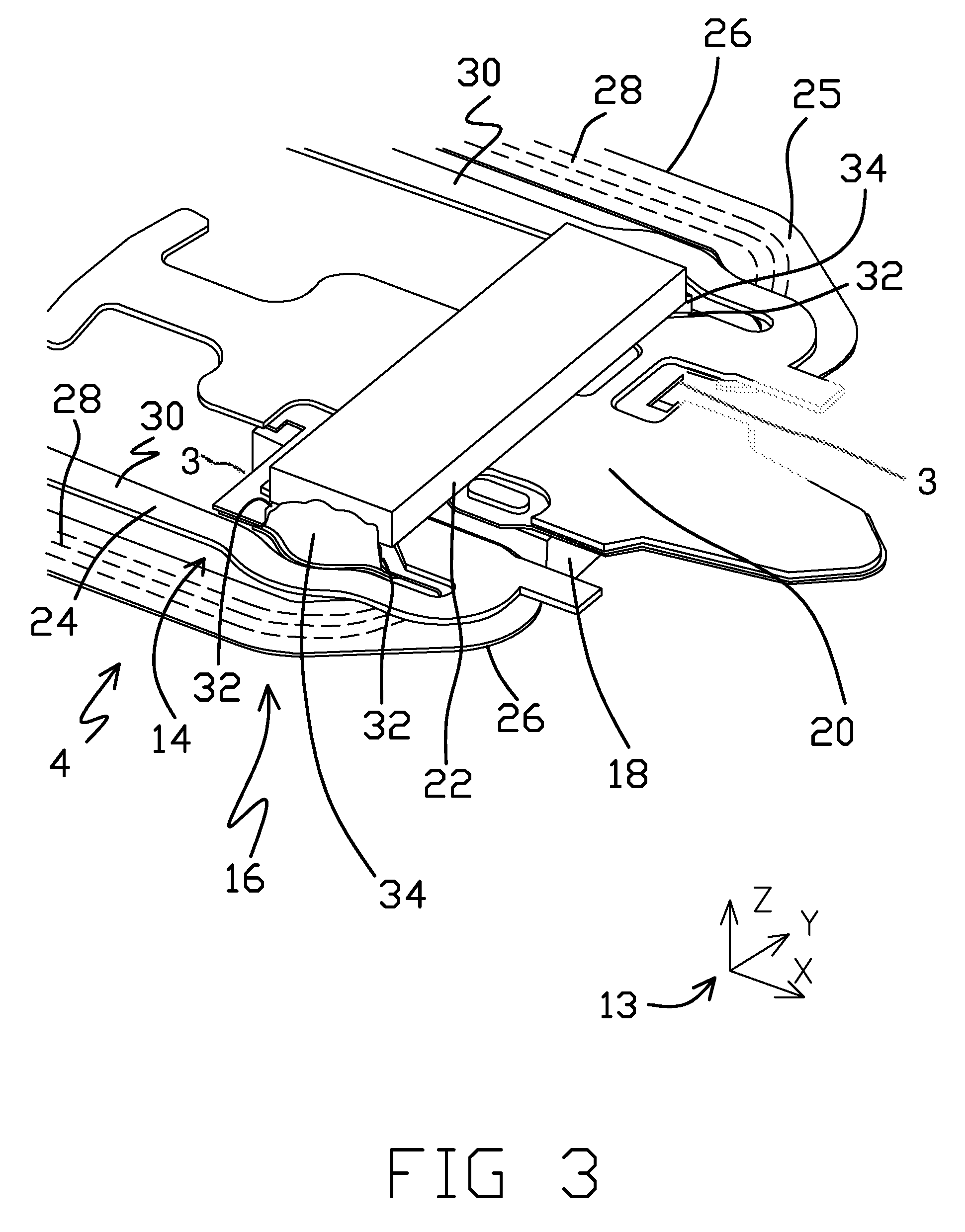
FIG. 3 is a perspective view of the stainless steel side of the distal end of a flexure with parts of the suspension removed from view to highlight the DSA structure having a motor.
FIG. 4 shows the same view of FIG. 3 but with the motor articulating the DSA structure in a first direction.
FIG. 5 shows the same view of FIGS. 3 and 4 but with the motor articulating the DSA structure in a second direction.
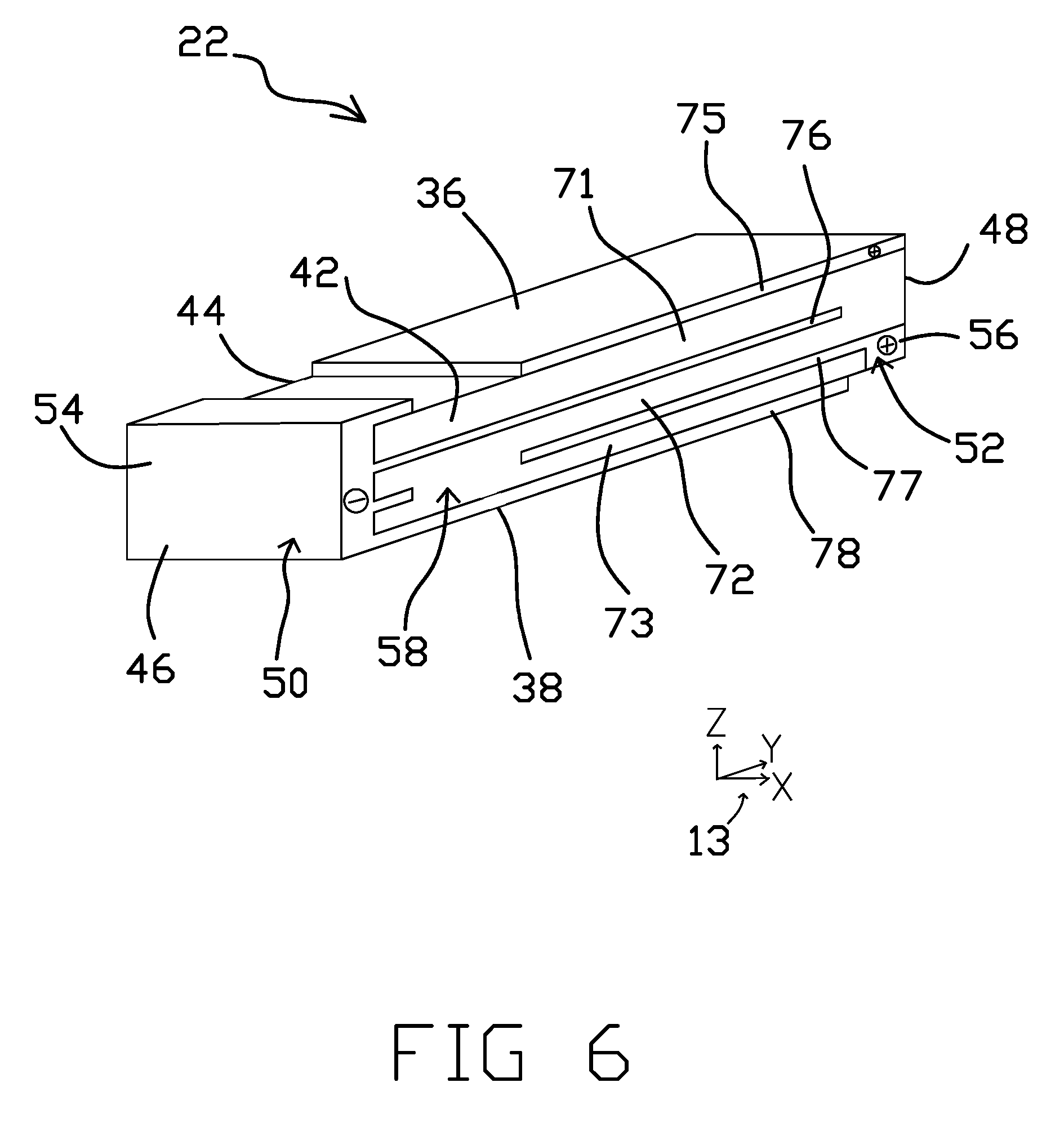
FIG. 6 is a detailed view of the motor of FIG. 3.
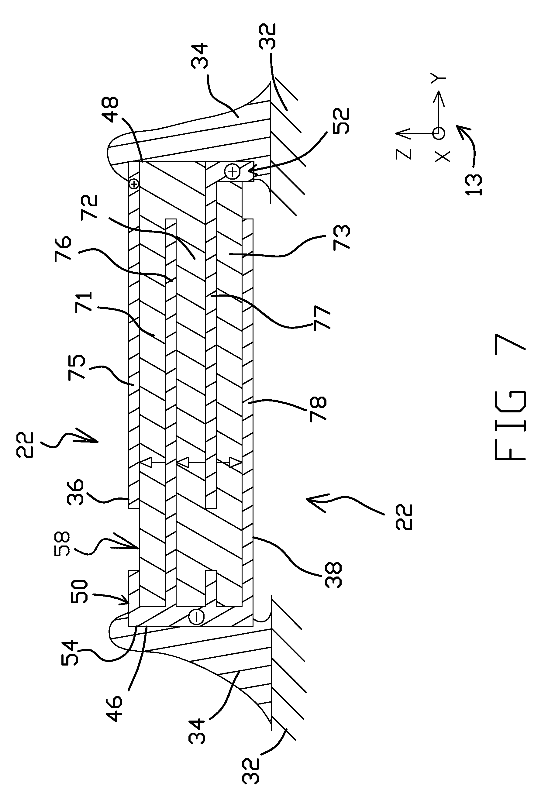
FIG. 7 is a cross sectional view of the motor of FIG. 3.
FIG. 8 shows the same cross sectional view of FIG. 7 but while the motor is activated to generally expand laterally.
FIG. 9 shows the same cross sectional view of FIG. 7 but while the motor is activated to generally contract laterally.
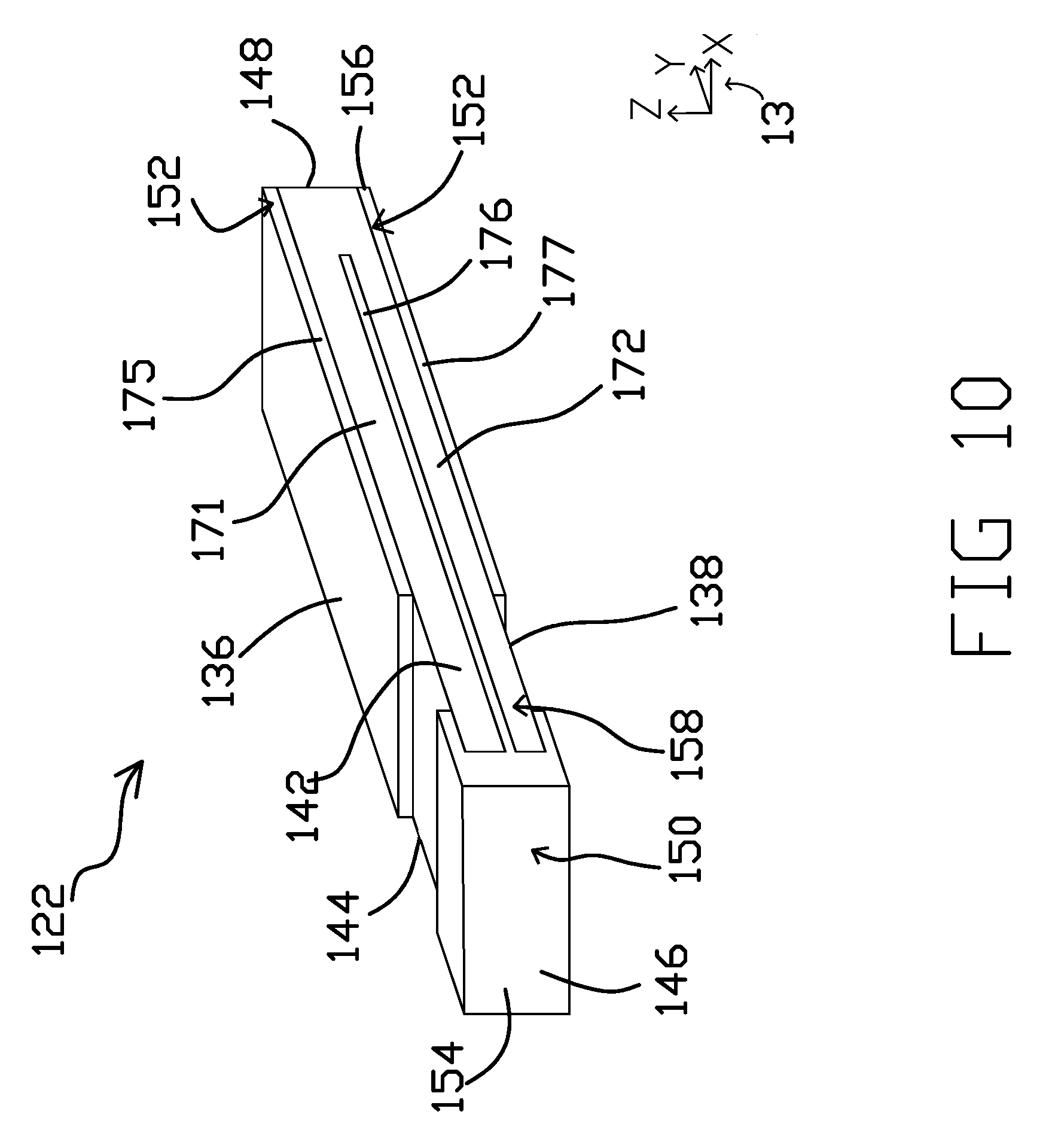
FIG. 10 is a detailed view of a motor.
FIG. 11 is a cross sectional view of the motor of FIG. 10.
While multiple embodiments are disclosed, still other embodiments within the scope of the present disclosure will become apparent to those skilled in the art from the following detailed description, which shows and describes illustrative embodiments. Accordingly, the drawings and detailed description are to be regarded as illustrative in nature and not restrictive.
DESCRIPTION OF THE INVENTION
FIG. 1 is a perspective view of the loadbeam side of a suspension 2 having a flexure 4 with a co-located or gimbal-based dual stage actuation (DSA) structure. As shown in FIG. 1, the suspension 2 includes a baseplate 6 as a proximal mounting structure. The suspension 2 includes a loadbeam 8 having a rigid or beam region 10 coupled to the baseplate 6 along a spring or hinge region 12. The loadbeam 8 can be formed from stainless steel. The flexure 4 includes a gimbal 14 at the distal end of the flexure 4. A DSA structure 16 is located on the gimbal 14, adjacent the distal end of the loadbeam 8. Proximal and distal, as used herein, refers to the relative direction along the longitudinal axis of the suspension 2. For example, the baseplate 6 is proximal of the loadbeam 8. An axes key 13 indicates X, Y, and Z axes in FIG. 1 and in subsequent FIGS. The suspension 2 is generally elongated along the X axis in distal and proximal directions. The Y axis represents lateral left and right directions. The suspension 2, including the flexure 4, are generally co-planar with an X-Y plane defined by the X and Y axes. The Z axis represents height as well as bottom and top orientations.
FIG. 2 is a detailed perspective view of the flexure side of the distal end of the suspension 2. FIG. 2 shows the opposite side of the suspension 2 relative to FIG. 1. A head slider 18 is mounted to a tongue 20 of the gimbal 14, on the side of the suspension 2 that is opposite the loadbeam 8. The slider 18 is mounted to a slider mounting region of the tongue 20. The slider mounting is a surface of the tongue 20 to which the slider 18 (or component to which the slider 18 is attached) can be attached, such as with an adhesive such as epoxy. It will be understood that the slider 18 can be attached to a different portion of the gimbal 14. FIG. 2 further shows a motor 22 mounted on the gimbal 14.
The flexure 4 is composed of several layers, as is known in the art. The flexure 4 includes a stainless steel layer 24. The stainless steel layer 24 can serve as a structural backbone to the flexure 4. Metals other than stainless steel can be used. The stainless steel layer 24 can include spring arms 30. The stainless steel layer 24 can further include a tongue 20. The tongue 20 can be supported by the spring arms 30. For example, struts 3 formed from the stainless steel layer 24 can bridge between the pair of spring arms 30 and the tongue 20 located there between.
The flexure 4 includes a trace portion 26. The trace portion 26 can be located partially on the stainless steel layer 24 and can extend off of the stainless steel layer 24 at various locations, such as in a flying lead segment. The trace portion 26 can comprise a plurality of traces 28 insulated by one or more dielectric layers 25. The traces 28 can be formed from copper or another conductive material. The dielectric layers 25 can be formed from polyimide or another polymer. The traces 28 can electrically connect proximally with control circuitry of a disk drive as in known in the art. The traces 28 can electrically connect distally to various components, such as the motor 22. The slider 18 can be electrically connected with one or more of the traces 28 for transmitting read and write signal along the suspension 2.
FIG. 3 is a perspective view of the stainless steel side of the distal end of a flexure 4 with parts of the suspension 2 removed from view to highlight the DSA structure 16. The DSA structure 16 includes the motor 22 mounted to the gimbal 14 of the flexure 4 between the loadbeam 8 (not shown in FIG. 3) and the head slider 18. As described in greater detail below, in response to electrical drive signals applied to the motor 22, the motor 22 drives portions of the gimbal 14, including the tongue 20 and slider 18, about a generally transverse tracking axis.
The connectors 34 attach the motor 22 to the flexure 4. Specifically, the pair of connectors 34 connect the lateral ends of the motor 22 to terminal pads 32 respectively located on the pair of spring arms 30. Lateral, as used herein, refers to the left and/or right directions orthogonal to the longitudinal axis of the suspension 2. The terminal pads 32 can be formed from metal (e.g., copper) and are exposed though the dielectric layer 25 of the flexure 4 to provide access for connectors 34 to make electrical connections with the traces 28. The connectors 34 can connect with respective anode and cathode terminals of the motor 22. Connectors 34 also mechanically support the motor 22 on the flexure 4. The connectors 34 can comprise solder, conductive epoxy (e.g., silver filled), or other material for forming an electrode connection.
In FIG. 3, the motor 22 is in a neutral, undriven state in which no tracking drive signal is applied to the motor 22. It is noted that the motor 22 in FIG. 3 has a planar profile along the X-Y plane (i.e. extending along proximal-distal and lateral axes). While the thickness of the motor 22 is measured along the Z axis (presenting height), the profile of the motor 22 is essentially entirely along the X-Y plane when in the neutral, undriven state. Rotation of the tongue 20 by actuation of the motor 22 rotates the slider mounting, and thereby the slider 18, about a tracking axis, as demonstrated in FIGS. 4 and 5 and further discussed herein.
FIG. 4 is a perspective view of the flexure 4 when the motor 22 is electrically activated to expand. In FIG. 4, a first drive signal is applied across the motor 22 via the traces 28 and connectors 34. The first drive signal (e.g., having a first polarity) causes the shape of the motor 22 to change. More specifically, the length of the motor 22 generally expands (e.g., along the Y axis). The expansion of the motor 22 mechanically causes the tongue 20, and the slider 18 mounted thereon, to deflect in a first direction about an axis of rotation. The axis of rotation is generally parallel with the Z axis. As shown, the motor 22 exhibits some out-of-plane (e.g., X-Y) motion (e.g., along the Z axis) upon the application of the first drive signal. More specifically, the motor 22 curls away from the flexure 4 when the motor 22 expands such that the lateral ends of the motor 22 move away from the slider 18 and the stainless steel layer 24 relative to the middle of the motor 22. The curling motion of the motor 22 means that the motor 22 is bending out of the X-Y plane and deflects along the Z axis.
FIG. 5 is the same perspective view of the flexure 4 as FIG. 4 except that in FIG. 5 the motor 22 is electrically activated to generally contract. The contraction is caused by application of a second drive signal (e.g., having a second polarity opposite the first polarity) across the motor 22 via the traces 28 and connectors 34. The contraction of the motor 22 mechanically causes the tongue 20, and the slider 18 mounted thereon, to deflect in a second direction about the axis of rotation, the second direction opposite the first direction. As shown, the motor 22 exhibits some out-of-plane motion along the Z-axis upon the application of the second drive signal. More specifically, the motor 22 curls toward the flexure 4 during contraction such that the lateral ends of the motor 22 move toward the slider 18 and the stainless steel layer 24 relative to the middle of the motor 22 which moves away the slider 18 and the stainless steel layer 24. The curling of the motor 22 causes the flexure 4 to curls in the same manner. This curling of the flexure 4 can be advantageous because the curling causes more total motion in the flexure 4. Such motion can be converted into rotation of the slider 18, which provides greater total stroke for articulation of the DSA structure 16. Out-of-plane Z-axis motion (curling) and in plane X or Y motion (stretching/contracting) of the motor 22 can both be used to move the flexure 4 and rotate the slider 18. There are various motor configurations that can support the curling profiles of FIGS. 4 and 5, as further discussed herein.
FIG. 6 is a detailed perspective view of the motor 22 and FIG. 7 is a cross-sectional view of the motor 22 which further shows connectors 34 and terminal pads 32. The motor 22 generally includes a top side 36, a bottom side 38 opposite the top side 36, a front side 42, a back side 44 opposite the front side 42, a first end side 46, and a second end side 48 opposite the first end side 46. The motor 22 includes a first terminal 50 and a second terminal 52. The first and second terminals 50, 52 can be formed from gold, copper, and/or other highly conductive material. The first terminal 50 includes a first end cap 54 which defines the first end side 46 of the motor 22. The first terminal 50 can further define a majority of the bottom side 38 as shown. The second terminal 52 includes a second end cap 56 which defines the second end side 48 of the motor 22. The second terminal 52 can include a first conductive layer 75, as further discussed herein. The first terminal 50 can be electrically connected to one side of a circuit of the flexure 4 while the second terminal 52 can be connected to the other side of the circuit, such that an electric potential can be applied across the motor 22, causing current to flow through the motor 22. The first terminal 50 is labeled as an anode while the second terminal 52 is labeled as a cathode for convenience. It will be understand that the first terminal 50 and the second terminal 52 can reversibly serve as either anode or cathode.
The motor 22 is comprised of multiple layers. The motor 22 includes a piezoelectric material 58. The piezoelectric material 58 can comprise lead titanate or various other materials that exhibit piezoelectric movement when subjected to an electric potential. The piezoelectric material 58 is divided into a plurality of piezoelectric material layers. The plurality of piezoelectric material layers includes a first actuator layer 71, a second actuator layer 72, and a third actuator layer 73. The plurality of piezoelectric layers are in a stacked (e.g., overlapping) arrangement. For example, the first actuator layer 71 is adjacent to the second actuator layer 72 and the second actuator layer 72 is adjacent to the third actuator layer 73. In some embodiments, the motor 22 can be limited to the first, second, and third actuator layers 71-73 and may not include any more actuator layers formed from piezoelectric material 58. Various other embodiments can include more than three actuator layers, such as four, five, or more actuator layers.
The motor 22 further comprises a plurality of conductive layers interleaved with the plurality of piezoelectric material layers. The plurality of conductive layers includes a first conductive layer 75 that defines the top side 36 of the motor 22. The plurality of conductive layers further comprises a second conductive layer 76, a third conductive layer 77, and a fourth conductive layer 78. The fourth conductive layer 78 defines the bottom side 38 of the motor 22. The top side of the first conductive layer 75 can be exposed on the top side 36 of the motor 22. In the arrangement of FIG. 6, the bottom side of the first conductive layer 75 is in contact with the top side of the first actuator layer 71. The bottom side of the first actuator layer 71 is in contact with the top side of the second conductive layer 76. The bottom side of the second conductive layer 76 is in contact with the top side of the second actuator layer 72. The bottom side of the second actuator layer 72 is in contact with the top side of the third conductive layer 77. The bottom side of the third conductive layer 77 is in contact with the top side of the third actuator layer 73. The bottom side of the third actuator layer 73 is in contact with the top side of the fourth conductive layer 78. The bottom side of the fourth conductive layer 78 can be exposed on the bottom side 38 of the motor 22.
In the embodiment of FIG. 6, the piezoelectric material 58 is continuous between the first, second, and third actuator layers 71-73. As shown, the first, second, and third actuator layers 71-73 form a serpentine shape around the second and third conductive layers 76, 77. In various other embodiments, such layers of the piezoelectric material 58 may not be in contact with each other and may be separated by one or more layers of non-piezoelectric material. In some embodiments, each of the plurality of actuator layers (e.g., first, second, and third actuator layers 71-73) are fabricated separately, including being poled, before being combined into the motor 22 as separate actuator layers. In this way, each actuator layer may be in contact with one or more other actuator layers in the motor 22, but the actuator layers may not be formed from a single piece of continuous piezoelectric material 58.
The plurality of conductive layers can be formed from conductive metal, such as gold or copper. The first terminal 50 can comprise the second and the fourth conductive layers 76, 78 as well as the first end cap 54. More specifically, the second and the fourth conductive layers 76, 78 can be connected to, or continuous with, the first end cap 54. The first and the third conductive layers 75, 77 are not directly connected (mechanically and electrically) to the first terminal 50. The second terminal 52 can comprise the first and the third conductive layers 75, 77 as well as the second end cap 56. While the first and third conductive layers 75, 77 are not directly connected to each other, these elements may be directly electrically connected to each other by the connector 34, such that a signal applied to the second terminal 52 is equally applied to each of the first and third conductive layers 75, 77. In alternative embodiments, the first and the third conductive layers 75, 77 can be directly connected to each other by the second end cap 56 extending along the second end side 48, such as by being continuous with each of the first and the third conductive layers 75, 77, similarly to how the first end cap 54 is attached to the second and fourth conductive layers 76, 78. The second and the fourth conductive layers 76, 78 are not directly connected (mechanically and electrically) to the second terminal 52. The first terminal 50 is not directly electrically connected to the second terminal 52. A differential signal applied across the first and second terminals 50, 52 causes current to flow through the piezoelectric material 58. The first, second, and third actuator layers 71-73 are electrically in parallel between the first and second terminals 50, 52 such that, in some configurations, approximately equal electric potentials will be developed in the first, second, and third actuator layers 71-73 and approximately equal levels of current will flow through the first, second, and third actuator layers 71-73. The differential signal causes an electric potential to be developed between the first conductive layer 75 and the second conductive layer 76, thereby causing current to flow between the first conductive layer 75 and the second conductive layer 76, through the first actuator layer 71 therebetween. The differential signal causes an electric potential to be developed between the second conductive layer 76 and the third conductive layer 77 thereby causing current to flow between the second conductive layer 76 and the third conductive layer 77, through the second actuator layer 72 therebetween. The differential signal causes an electric potential to be developed between the third conductive layer 77 and the fourth conductive layer 78 thereby causing current to flow between the third conductive layer 77 and the fourth conductive layer 78, through the third actuator layer 73 therebetween. This flow of current through the piezoelectric material 58 causes the first, second, and third actuator layers 71-73 to expand and contract, as further discussed herein.
The piezoelectric material 58 does not expand or contract in all dimensions equally upon application of the electrical signal. Rather, each layer of the first, second, and third actuator layers 71-73 has a particular dipole direction of the crystalline structure, the polarization of the signal and the dipole direction determining whether each actuator layer expands or contracts, as further discussed herein.
The piezoelectric material 58 has a crystalline structure which causes the material to change dimension most dramatically along one direction upon application of a differential signal across the first and second terminals 50, 52. Each cell of the crystalline structure functions as a dipole due to a charge imbalance across the cell. The orientations of the dipoles of the cells are generally random in untreated piezoelectric material 58. However, a processing step, called poling, can be performed on the piezoelectric material 58 during fabrication of the motor 22 to pole the dipoles in one desired orientation. During poling, untreated piezoelectric material 58 is subjected to a strong electric field that permanently reorientates most or all dipoles of the cells in a general or specific direction of the field. The process of poling can be performed layer-by-layer such that each of the first, second, and third actuator layers 71-73 (and other layers as provided) can be poled in a particular direction which may not be the same direction as the poling direction of the other layers. The direction along which the dipoles of a layer generally align is the poling direction. After the process of poling is complete, subsequent application of a differential signal (e.g., having a substantially lower strength than the electrical field used to pole the layers) causes more of the dipoles to reorientate along the poling direction and/or to causes the dipoles to more precisely align along the poling direction.
As such, each of the first, second, and third actuator layers 71-73 can have a similar or different dipole orientation with respect to the other layers. The poling direction, and the polarity of the signal across the layer relative to the poling direction, determines whether the layer expands or contracts in response to the differential signal. The arrows of FIG. 7 are used to indicate the relative poling of the first, second, and third actuator layers 71-73. It is noted that the directions of the arrows are used for convenience to distinguish the layers as having similar or different poling directions. The arrows themselves do not necessarily indicate the direction of dipole orientation. In some embodiments, the actual dipole orientation may extend along the longitudinal axis of each layer, (i.e. laterally).
As indicated by the arrows, the first and second actuator layers 71, 72 are poled in the same direction while the third actuator layer 73 is poled in a different direction (e.g., opposite the poling direction of the first and second actuator layers 71, 72). In this way, the dipole orientations of the crystalline structure of the first and second actuator layers 71, 72, are the same, which is in a different direction as the dipole orientation of the crystalline structure of the third actuator layer 73.
The relative poling of the first, second, and third actuator layers 71-73, and the arrangement of the first, second, third, and fourth conductive layers 75-78 alternatingly connecting to the first and second terminals 50, 52, causes the motor 22 to curl, as shown in FIG. 8. FIG. 8 is the same cross-sectional view as shown in FIG. 7, but during electrical activation of the motor 22. The first and second actuator layers 71, 72 are adjacent to one another, while the third actuator layer 73 is adjacent to the second actuator layer 72 and is poled in a different direction than the first and second actuator layers 71, 72. Furthermore, the plurality of conductive layers 75-78 alternate in polarity such that when a differential signal is applied across the motor 22, each of the first and second actuator layers 71, 72 will experience the signal at different polarities with respect to their poled orientations (even though both of the first and second actuator layers 71, 72 are poled in the same direction). The result is that one of the first and second actuator layers 71, 72 expand while the other of the first and second actuator layers 71, 72 will contract in response to the same signal applied across the motor 22. In the specific example of FIG. 8, the second actuator layer 72 expands while first actuator layer 71 contracts. Because of the reverse poling of the third actuator layer 73 with respect to the first and second actuator layers 71, 72, the third actuator layer 73 expands or contracts together with the second actuator layer 72, thus doing the opposite (i.e. expanding or contracting) of the first actuator layer 71. As shown in the example of FIG. 8, the third actuator layer 73 expands.
The second and third actuator layers 72, 73, will expand or contract together while the first actuator layer 71 will the other of expand or contract in synchrony with the second and third actuator layers 72, 73. More broadly, a pair of adjacent actuator layers will expand or contract together while an additional actuator layer, that is adjacent to one layer of the pair, will the other of expand or contract in opposite synchrony with the pair of adjacent actuator layers. The pair of adjacent second and third actuator layers 72, 73 expanding or contracting together drives the general longitudinal expansion or contraction of the motor 22, and thereby the deflection of the tongue 20 and slider 18. The expansion or contraction of the first actuator layer 71, opposite the motion of the pair of adjacent second and third actuator layers 72, 73, causes a disparity in motion within the motor 22. As shown in FIG. 8, the first actuator layer 71 is contracting which causes the expanding second and third actuator layers 72, 73 to partially curl around the first actuator layer 71. The layers of the motor are attached to one another as a whole such that the motor 22 curls to accommodate the disparity in motion, thereby causing the curling motion shown in FIGS. 4 and 8.
FIG. 9 is the same cross-sectional view as FIG. 8 but with the differential signal applied to the motor 22 being reversed in polarity. The polarity indicators on the first and second terminals 50, 52 are reversed relative to FIG. 8 to indicate the reversal of signal polarity. As shown in the example of FIG. 9, the first and second actuator layers 71, 72 contract laterally (e.g., along the Y-axis) while the third actuator layer 73 expands laterally, simultaneously. This disparity in lateral motion causes the expanding first actuator layer 71 to curl around the contracting second and third actuator layers 72, 73. This disparity in motion causes the motor 22 to curl as shown in FIG. 5.
It is noted that the poling directions of the first, second, and third actuator layers 71-73 are examples, and that other poling directions can be used for the various layers. For example, the poling directions of the first, second, and third actuator layers 71-73 can be reversed relative to what is shown in FIGS. 7-9. Some embodiments may correspond to the dipole orientations shown herein, but the motor 22 may be flipped. Other options are also possible.
In performance testing conducted by the inventors, a three layer motor similar to that shown in FIGS. 6-9 exhibited superior stoke performance relative to a standard five layer motor in which all layers were poled to expand or contract together. More specifically, the three layer motor was tested to have a 33.5 nanometer/volt stroke while the standard five layer motor was tested to have a 13.6 nanometer/volt stroke. Therefore, higher stroke performance can be achieved while using fewer actuator layers.
While three layer motors have been demonstrated herein in various embodiments, it is noted that various other embodiments can include a greater number of layers. Such motors can still exhibit the differential expanding/contracting motion as well as a greater number of expanding or contracting layers (e.g., three expanding layers and one or two contracting layers, which can be reversed to three contracting layers and one or two expanding layers). Furthermore, such motors can also include a pair of actuator layers that are adjacent to one another and that expand or contract together while another actuator layer, adjacent to one layer of the pair of actuator layers, expands while the pair of actuator layers contracts. For example, a top actuation layer can be added to the embodiment of FIG. 6 to extend above, and adjacent to, the first actuator layer 71 (e.g., in contact with the top side of the first conductive layer 75) A top conductive layer can then be added along the top side of the added top actuation layer in a similar manner to the first conductive layer 75. The top actuator layer can be poled in the same direction as the first actuator layer 71 or poled in the opposite direction. Instead of one top actuator layer being added, two top actuator layers may be added above the first actuator layer 71. Alternatively or additionally, one or two bottom actuator layers may be added to extend below, and adjacent to, the third actuator layer 73. Similar top and/or bottom actuators layers can be added to the motor 122 of FIGS. 10-11. For example, fourth and fifth actuator layers (not illustrated) can be added between the top and bottom conductive layers 175, 178, the fourth and fifth actuator layers stacked together with the first, second, and third actuator layers 171-173. The fourth and fifth actuator layers can both be above or below the first, second, and third actuator layers 171-173, or can be respectively above and below the first, second, and third actuator layers 171-173.
FIG. 10 is a detailed perspective view of a motor 122 having an alternative configuration. The motor 122 can be mounted on various flexures, such as that shown in FIGS. 1-5 or any other flexure referenced herein. The motor 122 can be fabricated and used in any manner referenced herein except where otherwise noted. FIG. 11 is a cross-sectional view of the motor 122 of FIG. 10. FIG. 11 further shows connectors 134 which can be used to electrically and mechanically connect the motor 122 to terminal pads 132 as disclosed herein. The motor 122 generally includes a top side 136, a bottom side 138 opposite the top side 136, a front side 142, a back side 144 opposite the front side 142, a first end side 146, and a second end side 148 opposite the first end side 146. The motor 122 includes a first terminal 150 and a second terminal 152. The first terminal 150 defines the first end side 146. The second terminal 152 defines part of the second end side 148. The second terminal 152 is comprised of a top conductive layer 175 and a bottom conductive layer 177. The top and bottom conductive layers 175, 177 may not contact each other, but as shown in FIG. 11, a connector 134 can contact each of the top and bottom conductive layers 175, 177 and electrically connect the top and bottom conductive layers 175, 177 such that they function as though they are directly electrically connected. Therefore, a signal applied to the bottom conductive layer 177 will freely conduct through the connector 134 to the top conductive layer 175 with negligible or no loss.
The first terminal 150 can be electrically connected to one side of a circuit of a flexure while the second terminal 152 can be connected to the other side of the circuit, such that an electrical potential can be applied across the motor 122, causing current to flow through the motor 122. It will be understood that the first terminal 150 and the second terminal 152 can each reversibly serve as either an anode or a cathode.
The motor 122 includes piezoelectric material 158. The piezoelectric material 158 can be similar to any piezoelectric material referenced herein. The piezoelectric material 158 includes only two piezoelectric layers. The piezoelectric material 158 includes a top actuator layer 171 and a bottom actuator layer 172. The motor 122 does not include any other piezoelectric layers. It is noted that the first and second actuator layers 171, 172 can be considered first and second actuator layers, respectively.
The motor 122 comprises a plurality of conductive layers. The plurality of conductive layers comprise a top conductive layer 175, a middle conductive layer 176, and a bottom conductive layer 177. The top conductive layer 175, the middle conductive layer 176, and the bottom conductive layer 177 can be considered first, second, and third conductive layers, respectively. The top conductive layer 175 defines the top side 136 of the motor 122. The bottom conductive layer 177 defines the bottom side 138 of the motor 122. The middle conductive layer 176 is sandwiched between the first and second actuator layers 171, 172. The top, middle, and bottom conductive layers 175-177 are in a stacked and interleaved arrangement with the first and second actuator layers 171, 172. A top side of the top conductive layer 175 can be exposed on the top side 136 of the motor 122. The bottom side of the top conductive layer 175 contacts the top side of the top actuator layer 171. A bottom side of the top actuator layer 171 contacts a top side of the middle conductive layer 176. A bottom side of the middle conductive layer 176 contacts a top side of the bottom actuator layer 172. A bottom side of the bottom actuator layer 172 contacts a top side of the bottom conductive layer 177. A bottom side of the bottom conductive layer 177 can be exposed on the bottom side 138 of the motor 122. The top, middle, and bottom conductive layers 175-177 can be similar to any conductive layer discussed herein, such as by being formed from a metal such as copper or gold. The first terminal 150 can be directly connected, or continuous, with the middle conductive layer 176.
As shown in FIG. 11, the first and second actuator layers 171, 172 are poled in the same direction. The piezoelectric material 158 is continuous between the first and second actuator layers 171, 172. As shown, the first and second actuator layers 171, 172 form a U shape and wrap around the middle conductive layers 176. In various other embodiments, the first and second actuator layers 171, 172 may not be in contact with each other and may be separated by one or more layers of non-piezoelectric material.
The arrows of FIG. 11 indicate the relative poling of the first and second actuator layers 171, 172 in similar manner to the arrows in FIG. 7. The first terminal 150 is not directly electrically connected to the second terminal 152. A differential signal applied across the first and second terminals 150, 152 causes current to flow through the piezoelectric material 158. The first and second actuator layers 171, 172 are electrically in parallel between the first and second terminals 150, 152 such that, in some configurations, approximately equal electric potentials will be developed in the first and second actuator layers 171, 172 and approximately equal levels of current will flow through the first and second actuator layers 171, 172. The differential signal causes an electric potential to be developed between the top conductive layer 175 and the middle conductive layer 176, thereby causing current to flow between the top conductive layer 175 and the middle conductive layer 176, through the top actuator layer 171 therebetween. The differential signal causes an electric potential to be developed between the middle conductive layer 176 and the bottom conductive layer 177 thereby causing current to flow between the middle conductive layer 176 and the bottom conductive layer 177, through the second actuator layer 72 therebetween. This flow of current through the piezoelectric material 158 causes the first and second actuator layers 171, 172 to expand and contract, as further discussed herein.
The poling of the first and second actuator layers 171, 172, and the arrangement of the top, middle, and bottom conductive layers 175-177 alternatingly connecting to the first and second terminals 150, 152, causes the motor 122 to curl upon activation. The first and second actuator layers 171, 172 are adjacent to one another while the top, middle, and bottom conductive layers 175-177 alternate in polarity such that when a differential signal is applied across the motor 122, each of the first and second actuator layers 171, 172 will experience the signal at different polarities with respect to their poled orientations (even though both of the first and second actuator layers 171, 172 are poled in the same direction). The result is that one of the first and second actuator layers 171, 172 expand while the other of the first and second actuator layers 171, 172 will contract in response to the same signal applied across the motor 122. Reversal of the signal polarity will likewise cause the expansion and contraction movements of the first and second actuator layers 171, 172 to reverse. Therefore, the only two actuator layers of the motor 122 will oppositely expand and contract in synchrony upon electrical activation. The expanding actuator layer will have a tendency to curl around the contracting actuator layer, as demonstrated herein in other embodiments.
In an alternative configuration of the embodiment of FIGS. 10 and 11, the middle conductive layer 176 may be removed, the poling direction of one of the first or second actuator layers 171, 172 may be reversed, and the first and second actuator layers 171, 172 can be electrically connected in series. Such an arrangement is similar to that shown in FIGS. 10 and 11 except that the motor only includes two actuator layers of opposite poling direction that oppositely expand and contract in synchrony upon electrical activation.
Although the present invention has been described with reference to preferred embodiments, those skilled in the art will recognize that changes can be made in form and detail without departing from the spirit and scope of the invention. For example, although described in connection with certain co-located DSA structures, motors and associated features described herein can be used in connection with other DSA structures, including other co-located DSA structures and/or non-co-located DSA structures, such as with baseplate 6 or loadbeam 8 mounted motors.
* * * * *
D00000
D00001
D00002
D00003
D00004
D00005
D00006
D00007
D00008
D00009
D00010
D00011
XML
uspto.report is an independent third-party trademark research tool that is not affiliated, endorsed, or sponsored by the United States Patent and Trademark Office (USPTO) or any other governmental organization. The information provided by uspto.report is based on publicly available data at the time of writing and is intended for informational purposes only.
While we strive to provide accurate and up-to-date information, we do not guarantee the accuracy, completeness, reliability, or suitability of the information displayed on this site. The use of this site is at your own risk. Any reliance you place on such information is therefore strictly at your own risk.
All official trademark data, including owner information, should be verified by visiting the official USPTO website at www.uspto.gov. This site is not intended to replace professional legal advice and should not be used as a substitute for consulting with a legal professional who is knowledgeable about trademark law.