Methods for delivery of prosthetic mitral valves
Vidlund , et al.
U.S. patent number 10,327,894 [Application Number 15/265,221] was granted by the patent office on 2019-06-25 for methods for delivery of prosthetic mitral valves. This patent grant is currently assigned to Tendyne Holdings, Inc.. The grantee listed for this patent is Tendyne Holdings, Inc.. Invention is credited to Igor Kovalsky, Robert M. Vidlund.


View All Diagrams
| United States Patent | 10,327,894 |
| Vidlund , et al. | June 25, 2019 |
Methods for delivery of prosthetic mitral valves
Abstract
In some embodiments, a method for delivery and deployment of a prosthetic mitral valve into a heart includes inserting an introducer sheath having a prosthetic mitral valve disposed therein in a collapsed configuration into the left atrium of a patient's heart, through a gap between the native mitral valve leaflets, the left ventricle and apex of the heart. An epicardial pad device coupled to the prosthetic valve via a tether is moved distally out of the sheath. The introducer sheath is withdrawn into the left atrium of the heart. An inner delivery sheath is extended distally from within the introducer sheath and disposed within the left atrium. The prosthetic mitral valve is moved distally out of the inner delivery sheath and assumes a biased expanded configuration. The valve is positioned within the mitral annulus of the heart, and secured in place via the tether and epicardial pad device.
| Inventors: | Vidlund; Robert M. (Forest Lake, MN), Kovalsky; Igor (Minnetonka, MN) | ||||||||||
|---|---|---|---|---|---|---|---|---|---|---|---|
| Applicant: |
|
||||||||||
| Assignee: | Tendyne Holdings, Inc. (St.
Paul, MN) |
||||||||||
| Family ID: | 58276393 | ||||||||||
| Appl. No.: | 15/265,221 | ||||||||||
| Filed: | September 14, 2016 |
Prior Publication Data
| Document Identifier | Publication Date | |
|---|---|---|
| US 20170079790 A1 | Mar 23, 2017 | |
Related U.S. Patent Documents
| Application Number | Filing Date | Patent Number | Issue Date | ||
|---|---|---|---|---|---|
| 62220704 | Sep 18, 2015 | ||||
| 62305678 | Mar 9, 2016 | ||||
| Current U.S. Class: | 1/1 |
| Current CPC Class: | A61F 2/2457 (20130101); A61F 2/2418 (20130101); A61B 17/0401 (20130101); A61B 17/0057 (20130101); A61B 2017/00663 (20130101); A61B 2017/00575 (20130101); A61B 2017/3425 (20130101); A61B 2017/0061 (20130101); A61B 2017/00592 (20130101); A61B 2017/0464 (20130101); A61B 2017/00358 (20130101); A61F 2/2427 (20130101); A61B 2017/0446 (20130101); A61B 2017/00623 (20130101); A61B 2017/0417 (20130101); A61F 2/2466 (20130101); A61B 2017/1142 (20130101); A61F 2230/005 (20130101); A61B 2017/0406 (20130101); A61F 2230/0078 (20130101); A61B 2017/00247 (20130101); A61F 2/2436 (20130101); A61B 2017/00597 (20130101); A61F 2250/0063 (20130101) |
| Current International Class: | A61F 2/24 (20060101); A61B 17/04 (20060101); A61B 17/00 (20060101); A61B 17/34 (20060101); A61B 17/11 (20060101) |
References Cited [Referenced By]
U.S. Patent Documents
| 2697008 | December 1954 | Rowley |
| 3409013 | November 1968 | Berry |
| 3472230 | October 1969 | Fogarty et al. |
| 3476101 | November 1969 | Ross |
| 3548417 | December 1970 | Kisher |
| 3587115 | June 1971 | Shiley |
| 3657744 | April 1972 | Ersek |
| 3671979 | June 1972 | Moulopoulos |
| 3714671 | February 1973 | Edwards et al. |
| 3755823 | September 1973 | Hancock |
| 3976079 | August 1976 | Samuels et al. |
| 4003382 | January 1977 | Dyke |
| 4035849 | July 1977 | Angell et al. |
| 4056854 | November 1977 | Boretos et al. |
| 4073438 | February 1978 | Meyer |
| 4106129 | August 1978 | Carpentier et al. |
| 4222126 | September 1980 | Boretos et al. |
| 4265694 | May 1981 | Boretos et al. |
| 4297749 | November 1981 | Davis et al. |
| 4339831 | July 1982 | Johnson |
| 4343048 | August 1982 | Ross et al. |
| 4345340 | August 1982 | Rosen |
| 4373216 | February 1983 | Klawitter |
| 4406022 | September 1983 | Roy |
| 4470157 | September 1984 | Love |
| 4490859 | January 1985 | Black et al. |
| 4535483 | August 1985 | Klawitter et al. |
| 4574803 | March 1986 | Storz |
| 4585705 | April 1986 | Broderick et al. |
| 4592340 | June 1986 | Boyles |
| 4605407 | August 1986 | Black et al. |
| 4612011 | September 1986 | Kautzky |
| 4626255 | December 1986 | Reichart et al. |
| 4638886 | January 1987 | Marietta |
| 4643732 | February 1987 | Pietsch et al. |
| 4655771 | April 1987 | Wallsten |
| 4692164 | September 1987 | Dzemeshkevich et al. |
| 4733665 | March 1988 | Palmaz |
| 4759758 | July 1988 | Gabbay |
| 4762128 | August 1988 | Rosenbluth |
| 4777951 | October 1988 | Cribier et al. |
| 4787899 | November 1988 | Lazarus |
| 4787901 | November 1988 | Baykut |
| 4796629 | January 1989 | Grayzel |
| 4824180 | April 1989 | Levrai |
| 4829990 | May 1989 | Thuroff et al. |
| 4830117 | May 1989 | Capasso |
| 4851001 | July 1989 | Taheri |
| 4856516 | August 1989 | Hillstead |
| 4878495 | November 1989 | Grayzel |
| 4878906 | November 1989 | Lindemann et al. |
| 4883458 | November 1989 | Shiber |
| 4922905 | May 1990 | Strecker |
| 4923013 | May 1990 | De Gennaro |
| 4960424 | October 1990 | Grooters |
| 4966604 | October 1990 | Reiss |
| 4979939 | December 1990 | Shiber |
| 4986830 | January 1991 | Owens et al. |
| 4994077 | February 1991 | Dobben |
| 4996873 | March 1991 | Takeuchi |
| 5007896 | April 1991 | Shiber |
| 5026366 | June 1991 | Leckrone |
| 5032128 | July 1991 | Alonso |
| 5035706 | July 1991 | Giantureo et al. |
| 5037434 | August 1991 | Lane |
| 5047041 | September 1991 | Sammuels |
| 5059177 | October 1991 | Towne et al. |
| 5064435 | November 1991 | Porter |
| 5080668 | January 1992 | Bolz et al. |
| 5085635 | February 1992 | Cragg |
| 5089015 | February 1992 | Ross |
| 5152771 | October 1992 | Sabbaghian et al. |
| 5163953 | November 1992 | Vince |
| 5167628 | December 1992 | Boyles |
| 5192297 | March 1993 | Hull |
| 5201880 | April 1993 | Wright et al. |
| 5266073 | November 1993 | Wall |
| 5282847 | February 1994 | Trescony et al. |
| 5295958 | March 1994 | Shturman |
| 5306296 | April 1994 | Wright et al. |
| 5332402 | July 1994 | Teitelbaum |
| 5336616 | August 1994 | Livesey et al. |
| 5344442 | September 1994 | Deac |
| 5360444 | November 1994 | Kusuhara |
| 5364407 | November 1994 | Poll |
| 5370685 | December 1994 | Stevens |
| 5397351 | March 1995 | Pavcnik et al. |
| 5411055 | May 1995 | Kane et al. |
| 5411552 | May 1995 | Andersen et al. |
| 5415667 | May 1995 | Frater |
| 5443446 | August 1995 | Shturman |
| 5480424 | January 1996 | Cox |
| 5500014 | March 1996 | Quijano et al. |
| 5545209 | August 1996 | Roberts et al. |
| 5545214 | August 1996 | Stevens |
| 5549665 | August 1996 | Vesely et al. |
| 5554184 | September 1996 | Machiraju |
| 5554185 | September 1996 | Block et al. |
| 5571175 | November 1996 | Vanney et al. |
| 5591185 | January 1997 | Kilmer et al. |
| 5607462 | March 1997 | Imran |
| 5607464 | March 1997 | Trescony et al. |
| 5609626 | March 1997 | Quijano et al. |
| 5639274 | June 1997 | Fischell et al. |
| 5662704 | September 1997 | Gross |
| 5665115 | September 1997 | Cragg |
| 5674279 | October 1997 | Wright et al. |
| 5697905 | December 1997 | Ambrosio |
| 5702368 | December 1997 | Stevens et al. |
| 5716417 | February 1998 | Girard et al. |
| 5728068 | March 1998 | Leone et al. |
| 5728151 | March 1998 | Garrison et al. |
| 5735842 | April 1998 | Krueger et al. |
| 5741333 | April 1998 | Frid |
| 5749890 | May 1998 | Shaknovich |
| 5756476 | May 1998 | Epstein |
| 5769812 | June 1998 | Stevens et al. |
| 5792179 | August 1998 | Sideris |
| 5800508 | September 1998 | Goicoechea et al. |
| 5833673 | November 1998 | Ockuly et al. |
| 5840081 | November 1998 | Andersen et al. |
| 5855597 | January 1999 | Jayaraman |
| 5855601 | January 1999 | Bessler |
| 5855602 | January 1999 | Angell |
| 5904697 | May 1999 | Gifford, III et al. |
| 5925063 | July 1999 | Khosravi |
| 5957949 | September 1999 | Leonhardt et al. |
| 5968052 | October 1999 | Sullivan, III et al. |
| 5968068 | October 1999 | Dehdashtian et al. |
| 5972030 | October 1999 | Garrison et al. |
| 5993481 | November 1999 | Marcade et al. |
| 6027525 | February 2000 | Suh et al. |
| 6042607 | March 2000 | Williamson, IV et al. |
| 6045497 | April 2000 | Schweich, Jr. et al. |
| 6063112 | May 2000 | Sgro et al. |
| 6077214 | June 2000 | Mortier et al. |
| 6099508 | August 2000 | Bousquet |
| 6132473 | October 2000 | Williams et al. |
| 6168614 | January 2001 | Andersen et al. |
| 6171335 | January 2001 | Wheatley et al. |
| 6174327 | January 2001 | Mertens et al. |
| 6183411 | February 2001 | Mortier et al. |
| 6210408 | April 2001 | Chandrasakaran et al. |
| 6217585 | April 2001 | Houser et al. |
| 6221091 | April 2001 | Khosravi |
| 6231602 | May 2001 | Carpentier et al. |
| 6245102 | June 2001 | Jayaraman |
| 6260552 | July 2001 | Mortier et al. |
| 6261222 | July 2001 | Schweich, Jr. et al. |
| 6264602 | July 2001 | Mortier et al. |
| 6287339 | September 2001 | Vazquez et al. |
| 6299637 | October 2001 | Shaolian |
| 6302906 | October 2001 | Goecoechea et al. |
| 6312465 | November 2001 | Griffin et al. |
| 6332893 | December 2001 | Mortier et al. |
| 6350277 | February 2002 | Kocur |
| 6358277 | March 2002 | Duran |
| 6379372 | April 2002 | Dehdashtian et al. |
| 6402679 | June 2002 | Mortier et al. |
| 6402680 | June 2002 | Mortier et al. |
| 6402781 | June 2002 | Langberg et al. |
| 6406420 | June 2002 | McCarthy et al. |
| 6425916 | July 2002 | Garrison et al. |
| 6440164 | August 2002 | Di Matteo et al. |
| 6454799 | September 2002 | Schreck |
| 6458153 | October 2002 | Bailey et al. |
| 6461382 | October 2002 | Cao |
| 6468660 | October 2002 | Ogle et al. |
| 6482228 | November 2002 | Norred |
| 6488704 | December 2002 | Connelly et al. |
| 6537198 | March 2003 | Vidlund et al. |
| 6540782 | April 2003 | Snyders |
| 6569196 | May 2003 | Vesely et al. |
| 6575252 | June 2003 | Reed |
| 6582462 | June 2003 | Andersen et al. |
| 6605112 | August 2003 | Moll |
| 6616684 | September 2003 | Vidlund et al. |
| 6622730 | September 2003 | Ekvall et al. |
| 6629534 | October 2003 | St. Goar et al. |
| 6629921 | October 2003 | Schweich, Jr. et al. |
| 6648077 | November 2003 | Hoffman |
| 6648921 | November 2003 | Anderson et al. |
| 6652578 | November 2003 | Bailey et al. |
| 6669724 | December 2003 | Park et al. |
| 6706065 | March 2004 | Langberg et al. |
| 6709456 | March 2004 | Langberg et al. |
| 6723038 | April 2004 | Schroeder et al. |
| 6726715 | April 2004 | Sutherland |
| 6730118 | May 2004 | Spenser et al. |
| 6733525 | May 2004 | Yang et al. |
| 6740105 | May 2004 | Yodfat et al. |
| 6746401 | June 2004 | Panescu |
| 6746471 | June 2004 | Mortier et al. |
| 6752813 | June 2004 | Goldfarb et al. |
| 6764510 | July 2004 | Vidlund et al. |
| 6797002 | September 2004 | Spence et al. |
| 6810882 | November 2004 | Langberg et al. |
| 6830584 | December 2004 | Seguin |
| 6854668 | February 2005 | Wancho et al. |
| 6855144 | February 2005 | Lesh |
| 6858001 | February 2005 | Aboul-Hosn |
| 6890353 | May 2005 | Cohn et al. |
| 6893460 | May 2005 | Spenser et al. |
| 6896690 | May 2005 | Lambrecht et al. |
| 6908424 | June 2005 | Mortier et al. |
| 6908481 | June 2005 | Cribier |
| 6936067 | August 2005 | Buchanan |
| 6945996 | September 2005 | Sedransk |
| 6955175 | October 2005 | Stevens et al. |
| 6974476 | December 2005 | McGuckin et al. |
| 6976543 | December 2005 | Fischer |
| 6997950 | February 2006 | Chawia |
| 7018406 | March 2006 | Seguin et al. |
| 7018408 | March 2006 | Bailey et al. |
| 7044905 | May 2006 | Vidlund et al. |
| 7060021 | June 2006 | Wilk |
| 7077862 | July 2006 | Vidlund et al. |
| 7087064 | August 2006 | Hyde |
| 7100614 | September 2006 | Stevens et al. |
| 7101395 | September 2006 | Tremulis et al. |
| 7108717 | September 2006 | Freidberg |
| 7112219 | September 2006 | Vidlund et al. |
| 7115141 | October 2006 | Menz et al. |
| 7141064 | November 2006 | Scott et al. |
| 7175656 | February 2007 | Khairkhahan |
| 7198646 | April 2007 | Figulla et al. |
| 7201772 | April 2007 | Schwammenthal et al. |
| 7247134 | July 2007 | Vidlund et al. |
| 7252682 | August 2007 | Seguin |
| 7267686 | September 2007 | DiMatteo et al. |
| 7275604 | October 2007 | Wall |
| 7276078 | October 2007 | Spenser et al. |
| 7276084 | October 2007 | Yang et al. |
| 7316706 | January 2008 | Bloom et al. |
| 7318278 | January 2008 | Zhang et al. |
| 7326236 | February 2008 | Andreas et al. |
| 7329278 | February 2008 | Seguin et al. |
| 7331991 | February 2008 | Kheradvar et al. |
| 7335213 | February 2008 | Hyde et al. |
| 7374571 | May 2008 | Pease et al. |
| 7377941 | May 2008 | Rhee et al. |
| 7381210 | June 2008 | Zarbatany et al. |
| 7381218 | June 2008 | Schreck |
| 7393360 | July 2008 | Spenser et al. |
| 7404824 | July 2008 | Webler et al. |
| 7416554 | August 2008 | Lam et al. |
| 7422072 | September 2008 | Dade |
| 7429269 | September 2008 | Schwammenthal et al. |
| 7442204 | October 2008 | Schwammenthal et al. |
| 7445631 | November 2008 | Salahieh et al. |
| 7462191 | December 2008 | Spenser et al. |
| 7470285 | December 2008 | Nugent et al. |
| 7500989 | March 2009 | Solem et al. |
| 7503931 | March 2009 | Kowalsky et al. |
| 7510572 | March 2009 | Gabbay |
| 7510575 | March 2009 | Spenser et al. |
| 7513908 | April 2009 | Lattouf |
| 7524330 | April 2009 | Berreklouw |
| 7527647 | May 2009 | Spence |
| 7534260 | May 2009 | Lattouf |
| 7556646 | July 2009 | Yang et al. |
| 7579381 | August 2009 | Dove |
| 7585321 | September 2009 | Cribier |
| 7591847 | September 2009 | Navia et al. |
| 7618446 | November 2009 | Andersen et al. |
| 7618447 | November 2009 | Case et al. |
| 7621948 | November 2009 | Herrmann et al. |
| 7632304 | December 2009 | Park |
| 7632308 | December 2009 | Loulmet |
| 7635386 | December 2009 | Gammie |
| 7674222 | March 2010 | Nikolic et al. |
| 7674286 | March 2010 | Alfieri et al. |
| 7695510 | April 2010 | Bloom et al. |
| 7708775 | May 2010 | Rowe et al. |
| 7748389 | July 2010 | Salahieh et al. |
| 7766961 | August 2010 | Patel et al. |
| 7789909 | September 2010 | Andersen et al. |
| 7803168 | September 2010 | Gifford et al. |
| 7803184 | September 2010 | McGuckin, Jr. et al. |
| 7803185 | September 2010 | Gabbay |
| 7806928 | October 2010 | Rowe et al. |
| 7837727 | November 2010 | Goetz et al. |
| 7854762 | December 2010 | Speziali et al. |
| 7892281 | February 2011 | Seguin et al. |
| 7896915 | March 2011 | Guyenot et al. |
| 7901454 | March 2011 | Kapadia et al. |
| 7927370 | April 2011 | Webler et al. |
| 7931630 | April 2011 | Nishtala et al. |
| 7942928 | May 2011 | Webler et al. |
| 7955247 | June 2011 | Levine et al. |
| 7955385 | June 2011 | Crittenden |
| 7972378 | July 2011 | Tabor et al. |
| 7988727 | August 2011 | Santamore et al. |
| 7993394 | August 2011 | Hariton et al. |
| 8007992 | August 2011 | Tian et al. |
| 8029556 | October 2011 | Rowe |
| 8043368 | October 2011 | Crabtree |
| 8052749 | November 2011 | Salahieh |
| 8052750 | November 2011 | Tuval et al. |
| 8052751 | November 2011 | Aklog et al. |
| 8062355 | November 2011 | Figulla et al. |
| 8062359 | November 2011 | Marquez et al. |
| 8070802 | December 2011 | Lamphere et al. |
| 8109996 | February 2012 | Stacchino et al. |
| 8142495 | March 2012 | Hasenkam et al. |
| 8152821 | April 2012 | Gambale et al. |
| 8157810 | April 2012 | Case et al. |
| 8167932 | May 2012 | Bourang et al. |
| 8167934 | May 2012 | Styrc et al. |
| 8187299 | May 2012 | Goldfarb et al. |
| 8206439 | June 2012 | Gomez Duran |
| 8216301 | July 2012 | Bonhoeffer et al. |
| 8226711 | July 2012 | Mortier et al. |
| 8236045 | August 2012 | Benichou et al. |
| 8241274 | August 2012 | Keogh et al. |
| 8252051 | August 2012 | Chau et al. |
| 8303653 | November 2012 | Bonhoeffer et al. |
| 8308796 | November 2012 | Lashinski et al. |
| 8323334 | December 2012 | Deem et al. |
| 8353955 | January 2013 | Styrc et al. |
| RE44075 | March 2013 | Williamson et al. |
| 8449599 | May 2013 | Chau et al. |
| 8454656 | June 2013 | Tuval |
| 8470028 | June 2013 | Thornton et al. |
| 8480730 | July 2013 | Maurer et al. |
| 8486138 | July 2013 | Vesely |
| 8506623 | August 2013 | Wilson et al. |
| 8506624 | August 2013 | Vidlund et al. |
| 8578705 | November 2013 | Sindano et al. |
| 8579913 | November 2013 | Nielsen |
| 8591573 | November 2013 | Barone |
| 8591576 | November 2013 | Hasenkam et al. |
| 8597347 | December 2013 | Maurer et al. |
| 8685086 | April 2014 | Navia et al. |
| 8790394 | July 2014 | Miller et al. |
| 8845717 | September 2014 | Khairkhahan et al. |
| 8888843 | November 2014 | Khairkhahan et al. |
| 8900214 | December 2014 | Nance et al. |
| 8900295 | December 2014 | Migliazza et al. |
| 8926696 | January 2015 | Cabiri et al. |
| 8932342 | January 2015 | McHugo et al. |
| 8932348 | January 2015 | Solem et al. |
| 8945208 | February 2015 | Jimenez et al. |
| 8956407 | February 2015 | Macoviak et al. |
| 8979922 | March 2015 | Thambar et al. |
| 8986376 | March 2015 | Solem |
| 9011522 | April 2015 | Annest et al. |
| 9023099 | May 2015 | Duffy et al. |
| 9034032 | May 2015 | McLean et al. |
| 9034033 | May 2015 | McLean et al. |
| 9039757 | May 2015 | McLean et al. |
| 9039759 | May 2015 | Alkhatib et al. |
| 9078645 | July 2015 | Conklin et al. |
| 9078749 | July 2015 | Lutter et al. |
| 9084676 | July 2015 | Chau et al. |
| 9095433 | August 2015 | Lutter et al. |
| 9125742 | September 2015 | Yoganathan et al. |
| 9149357 | October 2015 | Sequin |
| 9161837 | October 2015 | Kapadia |
| 9168137 | October 2015 | Subramanian et al. |
| 9232995 | January 2016 | Kovalsky et al. |
| 9232998 | January 2016 | Wilson et al. |
| 9232999 | January 2016 | Maurer et al. |
| 9241702 | January 2016 | Maisano et al. |
| 9254192 | February 2016 | Lutter et al. |
| 9265608 | February 2016 | Miller et al. |
| 9289295 | March 2016 | Aklog et al. |
| 9289297 | March 2016 | Wilson et al. |
| 9345573 | May 2016 | Nyuli et al. |
| 9480557 | November 2016 | Pellegrini et al. |
| 9480559 | November 2016 | Vidlund et al. |
| 9526611 | December 2016 | Tegels et al. |
| 9597181 | March 2017 | Christianson et al. |
| 9610159 | April 2017 | Christianson et al. |
| 9675454 | June 2017 | Vidlund et al. |
| 9730792 | August 2017 | Lutter et al. |
| 9827092 | November 2017 | Vidlund et al. |
| 9833315 | December 2017 | Vidlund et al. |
| 9867700 | January 2018 | Bakis et al. |
| 9883941 | February 2018 | Hastings et al. |
| 9895221 | February 2018 | Vidlund |
| 9986993 | June 2018 | Vidlund et al. |
| 2001/0018611 | August 2001 | Solem et al. |
| 2001/0021872 | September 2001 | Bailey et al. |
| 2001/0025171 | September 2001 | Mortier et al. |
| 2002/0010427 | January 2002 | Scarfone et al. |
| 2002/0116054 | August 2002 | Lundell et al. |
| 2002/0139056 | October 2002 | Finnell |
| 2002/0151961 | October 2002 | Lashinski et al. |
| 2002/0161377 | October 2002 | Rabkin |
| 2002/0173842 | November 2002 | Buchanan |
| 2002/0183827 | December 2002 | Derus |
| 2003/0010509 | January 2003 | Hoffman |
| 2003/0036698 | February 2003 | Kohler et al. |
| 2003/0050694 | March 2003 | Yang et al. |
| 2003/0078652 | April 2003 | Sutherland |
| 2003/0100939 | May 2003 | Yodfat et al. |
| 2003/0105519 | June 2003 | Fasol et al. |
| 2003/0105520 | June 2003 | Alferness et al. |
| 2003/0120340 | June 2003 | Liska et al. |
| 2003/0130731 | July 2003 | Vidlund et al. |
| 2003/0149476 | August 2003 | Damm et al. |
| 2003/0212454 | November 2003 | Scott et al. |
| 2004/0039436 | February 2004 | Spenser et al. |
| 2004/0049266 | March 2004 | Anduiza et al. |
| 2004/0064014 | April 2004 | Melvin et al. |
| 2004/0092858 | May 2004 | Wilson et al. |
| 2004/0093075 | May 2004 | Kuehne |
| 2004/0097865 | May 2004 | Anderson et al. |
| 2004/0127983 | July 2004 | Mortier et al. |
| 2004/0133263 | July 2004 | Dusbabek et al. |
| 2004/0147958 | July 2004 | Lam et al. |
| 2004/0152947 | August 2004 | Schroeder et al. |
| 2004/0162610 | August 2004 | Liska et al. |
| 2004/0163828 | August 2004 | Silverstein et al. |
| 2004/0181239 | September 2004 | Dorn et al. |
| 2004/0186565 | September 2004 | Schreck |
| 2004/0186566 | September 2004 | Hindrichs et al. |
| 2004/0260317 | December 2004 | Bloom et al. |
| 2004/0260389 | December 2004 | Case et al. |
| 2005/0004652 | January 2005 | Van Der Burg et al. |
| 2005/0004666 | January 2005 | Alfieri et al. |
| 2005/0075727 | April 2005 | Wheatley |
| 2005/0080402 | April 2005 | Santamore et al. |
| 2005/0085900 | April 2005 | Case |
| 2005/0096498 | May 2005 | Houser et al. |
| 2005/0107661 | May 2005 | Lau et al. |
| 2005/0113798 | May 2005 | Slater et al. |
| 2005/0113810 | May 2005 | Houser et al. |
| 2005/0113811 | May 2005 | Houser et al. |
| 2005/0119519 | June 2005 | Girard et al. |
| 2005/0121206 | June 2005 | Dolan |
| 2005/0125012 | June 2005 | Houser et al. |
| 2005/0137686 | June 2005 | Salahieh et al. |
| 2005/0137688 | June 2005 | Salahieh et al. |
| 2005/0137695 | June 2005 | Salahieh et al. |
| 2005/0137698 | June 2005 | Salahieh et al. |
| 2005/0148815 | July 2005 | Mortier et al. |
| 2005/0177180 | August 2005 | Kaganov et al. |
| 2005/0197695 | September 2005 | Stacchino |
| 2005/0203614 | September 2005 | Forster et al. |
| 2005/0203615 | September 2005 | Forster et al. |
| 2005/0203617 | September 2005 | Forster et al. |
| 2005/0234546 | October 2005 | Nugent et al. |
| 2005/0240200 | October 2005 | Bergheim |
| 2005/0251209 | November 2005 | Saadat et al. |
| 2005/0256567 | November 2005 | Lim et al. |
| 2005/0283231 | December 2005 | Haug |
| 2005/0288766 | December 2005 | Plain et al. |
| 2006/0004442 | January 2006 | Spenser et al. |
| 2006/0025784 | February 2006 | Starksen et al. |
| 2006/0025857 | February 2006 | Bergheim et al. |
| 2006/0030885 | February 2006 | Hyde |
| 2006/0042803 | March 2006 | Gallaher |
| 2006/0047338 | March 2006 | Jenson et al. |
| 2006/0052868 | March 2006 | Mortier et al. |
| 2006/0058872 | March 2006 | Salahieh et al. |
| 2006/0094983 | May 2006 | Burbank et al. |
| 2006/0129025 | June 2006 | Levine et al. |
| 2006/0142784 | June 2006 | Kontos |
| 2006/0161040 | July 2006 | McCarthy et al. |
| 2006/0161249 | July 2006 | Realyvasquez et al. |
| 2006/0167541 | July 2006 | Lattouf |
| 2006/0195134 | August 2006 | Crittenden |
| 2006/0195183 | August 2006 | Navia et al. |
| 2006/0229708 | October 2006 | Powell et al. |
| 2006/0229719 | October 2006 | Marquez et al. |
| 2006/0241745 | October 2006 | Solem |
| 2006/0247491 | November 2006 | Vidlund et al. |
| 2006/0252984 | November 2006 | Randert et al. |
| 2006/0259135 | November 2006 | Navia et al. |
| 2006/0259136 | November 2006 | Nguyen et al. |
| 2006/0259137 | November 2006 | Artof et al. |
| 2006/0276874 | December 2006 | Wilson |
| 2006/0282161 | December 2006 | Huynh et al. |
| 2006/0287716 | December 2006 | Banbury et al. |
| 2006/0287717 | December 2006 | Rowe et al. |
| 2007/0005131 | January 2007 | Taylor |
| 2007/0005231 | January 2007 | Seguchi |
| 2007/0010877 | January 2007 | Salahieh et al. |
| 2007/0016286 | January 2007 | Herrmann et al. |
| 2007/0016288 | January 2007 | Gurskis et al. |
| 2007/0027535 | February 2007 | Purdy et al. |
| 2007/0038291 | February 2007 | Case et al. |
| 2007/0050020 | March 2007 | Spence |
| 2007/0061010 | March 2007 | Hauser et al. |
| 2007/0066863 | March 2007 | Rafiee et al. |
| 2007/0073387 | March 2007 | Forster et al. |
| 2007/0078297 | April 2007 | Rafiee et al. |
| 2007/0083076 | April 2007 | Lichtenstein |
| 2007/0083259 | April 2007 | Bloom et al. |
| 2007/0093890 | April 2007 | Eliasen et al. |
| 2007/0100439 | May 2007 | Cangialosi et al. |
| 2007/0112422 | May 2007 | Dehdashtian |
| 2007/0112425 | May 2007 | Schaller et al. |
| 2007/0118151 | May 2007 | Davidson |
| 2007/0118154 | May 2007 | Crabtree |
| 2007/0118210 | May 2007 | Pinchuk |
| 2007/0118213 | May 2007 | Loulmet |
| 2007/0142906 | June 2007 | Figulla |
| 2007/0161846 | July 2007 | Nikolic et al. |
| 2007/0162048 | July 2007 | Quinn et al. |
| 2007/0162103 | July 2007 | Case et al. |
| 2007/0168024 | July 2007 | Khairkhahan |
| 2007/0185565 | August 2007 | Schwammenthal et al. |
| 2007/0185571 | August 2007 | Kapadia et al. |
| 2007/0203575 | August 2007 | Forster et al. |
| 2007/0213813 | September 2007 | Von Segesser et al. |
| 2007/0215362 | September 2007 | Rodgers |
| 2007/0221388 | September 2007 | Johnson |
| 2007/0233239 | October 2007 | Navia et al. |
| 2007/0239265 | October 2007 | Birdsall |
| 2007/0256843 | November 2007 | Pahila |
| 2007/0265658 | November 2007 | Nelson et al. |
| 2007/0267202 | November 2007 | Mariller |
| 2007/0270932 | November 2007 | Headley et al. |
| 2007/0270943 | November 2007 | Solem |
| 2007/0293944 | December 2007 | Spenser et al. |
| 2008/0009940 | January 2008 | Cribier |
| 2008/0033543 | February 2008 | Gurskis et al. |
| 2008/0065011 | March 2008 | Marchand et al. |
| 2008/0071361 | March 2008 | Tuval et al. |
| 2008/0071362 | March 2008 | Tuval et al. |
| 2008/0071363 | March 2008 | Tuval et al. |
| 2008/0071366 | March 2008 | Tuval et al. |
| 2008/0071368 | March 2008 | Tuval et al. |
| 2008/0071369 | March 2008 | Tuval et al. |
| 2008/0082163 | April 2008 | Woo |
| 2008/0082166 | April 2008 | Styrc et al. |
| 2008/0091264 | April 2008 | Machold et al. |
| 2008/0114442 | May 2008 | Mitchell et al. |
| 2008/0125861 | May 2008 | Webler et al. |
| 2008/0147179 | June 2008 | Cai et al. |
| 2008/0154355 | June 2008 | Benichou et al. |
| 2008/0154356 | June 2008 | Obermiller et al. |
| 2008/0161911 | July 2008 | Revuelta et al. |
| 2008/0172035 | July 2008 | Starksen et al. |
| 2008/0177381 | July 2008 | Navia et al. |
| 2008/0183203 | July 2008 | Fitzgerald et al. |
| 2008/0183273 | July 2008 | Mesana et al. |
| 2008/0188928 | August 2008 | Salahieh et al. |
| 2008/0208328 | August 2008 | Antocci et al. |
| 2008/0208332 | August 2008 | Lamphere et al. |
| 2008/0221672 | September 2008 | Lamphere et al. |
| 2008/0243150 | October 2008 | Starksen et al. |
| 2008/0243245 | October 2008 | Thambar et al. |
| 2008/0255660 | October 2008 | Guyenot et al. |
| 2008/0255661 | October 2008 | Straubinger et al. |
| 2008/0281411 | November 2008 | Berreklouw |
| 2008/0288060 | November 2008 | Kaye et al. |
| 2008/0293996 | November 2008 | Evans et al. |
| 2009/0005863 | January 2009 | Goetz et al. |
| 2009/0048668 | February 2009 | Wilson et al. |
| 2009/0054968 | February 2009 | Bonhoeffer |
| 2009/0054974 | February 2009 | McGuckin, Jr. et al. |
| 2009/0062908 | March 2009 | Bonhoeffer et al. |
| 2009/0076598 | March 2009 | Salahieh et al. |
| 2009/0082619 | March 2009 | De Marchena |
| 2009/0088836 | April 2009 | Bishop et al. |
| 2009/0099410 | April 2009 | De Marchena |
| 2009/0112309 | April 2009 | Jaramillo |
| 2009/0131849 | May 2009 | Maurer et al. |
| 2009/0132035 | May 2009 | Roth et al. |
| 2009/0137861 | May 2009 | Goldberg et al. |
| 2009/0138079 | May 2009 | Tuval et al. |
| 2009/0157175 | June 2009 | Benichou |
| 2009/0164005 | June 2009 | Dove et al. |
| 2009/0171432 | July 2009 | Von Segesser et al. |
| 2009/0171447 | July 2009 | Von Segesser et al. |
| 2009/0171456 | July 2009 | Kveen et al. |
| 2009/0177266 | July 2009 | Powell et al. |
| 2009/0192601 | July 2009 | Rafiee et al. |
| 2009/0210052 | August 2009 | Forster et al. |
| 2009/0216322 | August 2009 | Le et al. |
| 2009/0222076 | September 2009 | Figulla et al. |
| 2009/0224529 | September 2009 | Gill |
| 2009/0234318 | September 2009 | Loulmet et al. |
| 2009/0234435 | September 2009 | Johnson et al. |
| 2009/0234443 | September 2009 | Ottma et al. |
| 2009/0240320 | September 2009 | Tuval et al. |
| 2009/0248149 | October 2009 | Gabbay |
| 2009/0276040 | November 2009 | Rowe |
| 2009/0281619 | November 2009 | Le et al. |
| 2009/0287299 | November 2009 | Tabor et al. |
| 2009/0292262 | November 2009 | Adams |
| 2009/0319037 | December 2009 | Rowe et al. |
| 2009/0326575 | December 2009 | Galdonik et al. |
| 2010/0016958 | January 2010 | St. Goar et al. |
| 2010/0021382 | January 2010 | Dorshow et al. |
| 2010/0023117 | January 2010 | Yoganathan et al. |
| 2010/0036479 | February 2010 | Hill et al. |
| 2010/0049313 | February 2010 | Alon et al. |
| 2010/0082094 | April 2010 | Quadri et al. |
| 2010/0161041 | June 2010 | Maisano et al. |
| 2010/0168839 | July 2010 | Braido et al. |
| 2010/0179641 | July 2010 | Ryan et al. |
| 2010/0185277 | July 2010 | Braido et al. |
| 2010/0185278 | July 2010 | Schankereli |
| 2010/0191326 | July 2010 | Alkhatib |
| 2010/0192402 | August 2010 | Yamaguchi et al. |
| 2010/0204781 | August 2010 | Alkhatib |
| 2010/0210899 | August 2010 | Schankereli |
| 2010/0217382 | August 2010 | Chau |
| 2010/0249489 | September 2010 | Jarvik |
| 2010/0249923 | September 2010 | Alkhatib et al. |
| 2010/0280604 | November 2010 | Zipory et al. |
| 2010/0286768 | November 2010 | Alkhatib |
| 2010/0298755 | November 2010 | McNamara et al. |
| 2010/0298931 | November 2010 | Quadri et al. |
| 2011/0004296 | January 2011 | Lutter |
| 2011/0015616 | January 2011 | Straubinger et al. |
| 2011/0015728 | January 2011 | Jimenez et al. |
| 2011/0015729 | January 2011 | Jimenez et al. |
| 2011/0029072 | February 2011 | Gabbay |
| 2011/0066231 | March 2011 | Cartledge et al. |
| 2011/0066233 | March 2011 | Thornton et al. |
| 2011/0112632 | May 2011 | Chau et al. |
| 2011/0137397 | June 2011 | Chau et al. |
| 2011/0137408 | June 2011 | Bergheim |
| 2011/0224655 | September 2011 | Asirvatham et al. |
| 2011/0224678 | September 2011 | Gabbay |
| 2011/0224728 | September 2011 | Martin et al. |
| 2011/0224784 | September 2011 | Quinn |
| 2011/0245911 | October 2011 | Quill et al. |
| 2011/0251682 | October 2011 | Murray, III et al. |
| 2011/0264191 | October 2011 | Rothstein |
| 2011/0264206 | October 2011 | Tabor |
| 2011/0288637 | November 2011 | De Marchena |
| 2011/0319988 | December 2011 | Schankereli et al. |
| 2011/0319989 | December 2011 | Lane et al. |
| 2012/0010694 | January 2012 | Lutter et al. |
| 2012/0016468 | January 2012 | Robin et al. |
| 2012/0022640 | January 2012 | Gross et al. |
| 2012/0035703 | February 2012 | Lutter et al. |
| 2012/0035713 | February 2012 | Lutter et al. |
| 2012/0035722 | February 2012 | Tuval |
| 2012/0053686 | March 2012 | McNamara et al. |
| 2012/0059487 | March 2012 | Cunanan et al. |
| 2012/0089171 | April 2012 | Hastings et al. |
| 2012/0101571 | April 2012 | Thambar et al. |
| 2012/0101572 | April 2012 | Kovalsky et al. |
| 2012/0116351 | May 2012 | Chomas et al. |
| 2012/0123529 | May 2012 | Levi et al. |
| 2012/0165930 | June 2012 | Gifford et al. |
| 2012/0179244 | July 2012 | Schankereli et al. |
| 2012/0203336 | August 2012 | Annest |
| 2012/0215303 | August 2012 | Quadri et al. |
| 2012/0226348 | September 2012 | Lane et al. |
| 2012/0283824 | November 2012 | Lutter et al. |
| 2012/0289945 | November 2012 | Segermark |
| 2013/0030522 | January 2013 | Rowe et al. |
| 2013/0053950 | February 2013 | Rowe et al. |
| 2013/0066341 | March 2013 | Ketai et al. |
| 2013/0079873 | March 2013 | Migliazza et al. |
| 2013/0131788 | May 2013 | Quadri et al. |
| 2013/0172978 | July 2013 | Vidlund |
| 2013/0184811 | July 2013 | Rowe |
| 2013/0190860 | July 2013 | Sundt, III |
| 2013/0190861 | July 2013 | Chau et al. |
| 2013/0197622 | August 2013 | Mitra et al. |
| 2013/0226288 | August 2013 | Goldwasser et al. |
| 2013/0231735 | September 2013 | Deem et al. |
| 2013/0274874 | October 2013 | Hammer |
| 2013/0282101 | October 2013 | Eidenschink et al. |
| 2013/0310928 | November 2013 | Morriss et al. |
| 2013/0317603 | November 2013 | McLean et al. |
| 2013/0325041 | December 2013 | Annest et al. |
| 2013/0325110 | December 2013 | Khalil et al. |
| 2013/0338752 | December 2013 | Geusen et al. |
| 2014/0046433 | February 2014 | Kovalsky |
| 2014/0081323 | March 2014 | Hawkins |
| 2014/0094918 | April 2014 | Vishnubholta et al. |
| 2014/0142691 | May 2014 | Pouletty |
| 2014/0163668 | June 2014 | Rafiee |
| 2014/0194981 | July 2014 | Menk et al. |
| 2014/0194983 | July 2014 | Kovalsky |
| 2014/0214159 | July 2014 | Vidlund |
| 2014/0222142 | August 2014 | Kovalsky |
| 2014/0243966 | August 2014 | Garde et al. |
| 2014/0277419 | September 2014 | Garde et al. |
| 2014/0296969 | October 2014 | Tegels et al. |
| 2014/0296970 | October 2014 | Ekvall et al. |
| 2014/0296971 | October 2014 | Tegels et al. |
| 2014/0296972 | October 2014 | Tegels et al. |
| 2014/0296975 | October 2014 | Tegels et al. |
| 2014/0303718 | October 2014 | Tegels et al. |
| 2014/0309732 | October 2014 | Solem |
| 2014/0316516 | October 2014 | Vidlund et al. |
| 2014/0324160 | October 2014 | Benichou et al. |
| 2014/0324161 | October 2014 | Tegels et al. |
| 2014/0324164 | October 2014 | Gross et al. |
| 2014/0331475 | November 2014 | Duffy |
| 2014/0358224 | December 2014 | Tegels et al. |
| 2014/0364942 | December 2014 | Straubinger |
| 2014/0364944 | December 2014 | Lutter et al. |
| 2014/0379076 | December 2014 | Vidlund et al. |
| 2015/0005874 | January 2015 | Vidlund et al. |
| 2015/0011821 | January 2015 | Gorman et al. |
| 2015/0025553 | January 2015 | Del Nido et al. |
| 2015/0057705 | February 2015 | Vidlund et al. |
| 2015/0073542 | March 2015 | Heldman |
| 2015/0073545 | March 2015 | Braido |
| 2015/0094802 | April 2015 | Buchbinder et al. |
| 2015/0105856 | April 2015 | Rowe et al. |
| 2015/0119936 | April 2015 | Gilmore et al. |
| 2015/0119978 | April 2015 | Tegels et al. |
| 2015/0127093 | May 2015 | Hosmer et al. |
| 2015/0127096 | May 2015 | Rowe et al. |
| 2015/0134050 | May 2015 | Solem |
| 2015/0142100 | May 2015 | Morriss et al. |
| 2015/0142101 | May 2015 | Coleman et al. |
| 2015/0142103 | May 2015 | Vidlund |
| 2015/0142104 | May 2015 | Braido |
| 2015/0173897 | June 2015 | Raanani et al. |
| 2015/0196393 | July 2015 | Vidlund et al. |
| 2015/0196688 | July 2015 | James et al. |
| 2015/0202044 | July 2015 | Chau et al. |
| 2015/0216653 | August 2015 | Freudenthanl |
| 2015/0216660 | August 2015 | Pintor et al. |
| 2015/0223820 | August 2015 | Olson et al. |
| 2015/0223934 | August 2015 | Vidlund et al. |
| 2015/0238312 | August 2015 | Lashinski |
| 2015/0238729 | August 2015 | Jenson et al. |
| 2015/0272731 | October 2015 | Racchini et al. |
| 2015/0305860 | October 2015 | Wang et al. |
| 2015/0305864 | October 2015 | Quadri et al. |
| 2015/0305868 | October 2015 | Lutter et al. |
| 2015/0327995 | November 2015 | Morin et al. |
| 2015/0328001 | November 2015 | McLean et al. |
| 2015/0335424 | November 2015 | McLean et al. |
| 2015/0335429 | November 2015 | Morriss et al. |
| 2015/0342717 | December 2015 | O'Donnell et al. |
| 2015/0351903 | December 2015 | Morriss et al. |
| 2015/0351906 | December 2015 | Hammer et al. |
| 2016/0000562 | January 2016 | Siegel |
| 2016/0008131 | January 2016 | Christianson et al. |
| 2016/0067042 | March 2016 | Murad et al. |
| 2016/0074160 | March 2016 | Christianson et al. |
| 2016/0106537 | April 2016 | Christianson et al. |
| 2016/0113764 | April 2016 | Sheahan et al. |
| 2016/0143736 | May 2016 | Vidlund et al. |
| 2016/0151155 | June 2016 | Lutter et al. |
| 2016/0206280 | July 2016 | Vidlund et al. |
| 2016/0242902 | August 2016 | Morriss et al. |
| 2016/0262879 | September 2016 | Meiri et al. |
| 2016/0262881 | September 2016 | Schankereli et al. |
| 2016/0278955 | September 2016 | Liu |
| 2016/0317290 | November 2016 | Chau et al. |
| 2016/0324635 | November 2016 | Vidlund et al. |
| 2016/0331527 | November 2016 | Vidlund et al. |
| 2016/0346086 | December 2016 | Solem |
| 2016/0367365 | December 2016 | Conklin |
| 2016/0367367 | December 2016 | Maisano et al. |
| 2016/0367368 | December 2016 | Vidlund et al. |
| 2017/0100248 | April 2017 | Tegels et al. |
| 2017/0128208 | May 2017 | Christianson et al. |
| 2017/0181854 | June 2017 | Christianson et al. |
| 2017/0196688 | July 2017 | Christianson et al. |
| 2017/0252153 | September 2017 | Chau et al. |
| 2017/0266001 | September 2017 | Vidlund et al. |
| 2017/0281343 | October 2017 | Christianson et al. |
| 2017/0312076 | November 2017 | Lutter et al. |
| 2017/0312077 | November 2017 | Vidlund et al. |
| 2017/0319333 | November 2017 | Tegels et al. |
| 2018/0028314 | February 2018 | Ekvall et al. |
| 2018/0078368 | March 2018 | Vidlund et al. |
| 2018/0078370 | March 2018 | Kovalsky et al. |
| 2018/0147055 | May 2018 | Vidlund et al. |
| 1486161 | Mar 2004 | CN | |||
| 1961845 | May 2007 | CN | |||
| 2902226 | May 2007 | CN | |||
| 101146484 | Mar 2008 | CN | |||
| 101180010 | May 2008 | CN | |||
| 101984938 | Mar 2011 | CN | |||
| 102869317 | Jan 2013 | CN | |||
| 102869318 | Jan 2013 | CN | |||
| 102869321 | Jan 2013 | CN | |||
| 103220993 | Jul 2013 | CN | |||
| 102639179 | Oct 2014 | CN | |||
| 2246526 | Mar 1973 | DE | |||
| 19532846 | Mar 1997 | DE | |||
| 19546692 | Jun 1997 | DE | |||
| 19857887 | Jul 2000 | DE | |||
| 19907646 | Aug 2000 | DE | |||
| 10049812 | Apr 2002 | DE | |||
| 10049813 | Apr 2002 | DE | |||
| 10049815 | Apr 2002 | DE | |||
| 102006052564 | Dec 2007 | DE | |||
| 102006052710 | May 2008 | DE | |||
| 102007043830 | Apr 2009 | DE | |||
| 102007043831 | Apr 2009 | DE | |||
| 0103546 | May 1988 | EP | |||
| 1057460 | Dec 2000 | EP | |||
| 1088529 | Apr 2001 | EP | |||
| 1469797 | Nov 2005 | EP | |||
| 2111800 | Oct 2009 | EP | |||
| 2193762 | Jun 2010 | EP | |||
| 2747707 | Apr 2015 | EP | |||
| 2918248 | Sep 2015 | EP | |||
| 2278944 | Mar 2016 | EP | |||
| 2788217 | Jul 2000 | FR | |||
| 2815844 | May 2002 | FR | |||
| 2003-505146 | Dec 2003 | JP | |||
| 2005-515836 | Jun 2005 | JP | |||
| 2009-514628 | Apr 2009 | JP | |||
| 2009-519783 | May 2009 | JP | |||
| 2013-512765 | Apr 2013 | JP | |||
| 1017275 | Aug 2002 | NL | |||
| 1271508 | Nov 1986 | SU | |||
| WO 92/17118 | Oct 1992 | WO | |||
| WO 93/01768 | Feb 1993 | WO | |||
| WO 98/29057 | Jul 1998 | WO | |||
| WO 99/40964 | Aug 1999 | WO | |||
| WO 99/47075 | Sep 1999 | WO | |||
| WO 2000/018333 | Apr 2000 | WO | |||
| WO 2000/030550 | Jun 2000 | WO | |||
| WO 2000/041652 | Jul 2000 | WO | |||
| WO 2000/047139 | Aug 2000 | WO | |||
| WO 2001/035878 | May 2001 | WO | |||
| WO 2001/049213 | Jul 2001 | WO | |||
| WO 2001/054624 | Aug 2001 | WO | |||
| WO 2001/054625 | Aug 2001 | WO | |||
| WO 2001/056512 | Aug 2001 | WO | |||
| WO 2001/061289 | Aug 2001 | WO | |||
| WO 2001/076510 | Oct 2001 | WO | |||
| WO 2001/082840 | Nov 2001 | WO | |||
| WO 2002/004757 | Jan 2002 | WO | |||
| WO 2002/022054 | Mar 2002 | WO | |||
| WO 2002/028321 | Apr 2002 | WO | |||
| WO 2002/036048 | May 2002 | WO | |||
| WO 2002/041789 | May 2002 | WO | |||
| WO 2002/043620 | Jun 2002 | WO | |||
| WO 2002/049540 | Jun 2002 | WO | |||
| WO 2002/076348 | Oct 2002 | WO | |||
| WO 2003/003943 | Jan 2003 | WO | |||
| WO 2003/030776 | Apr 2003 | WO | |||
| WO 2003/047468 | Jun 2003 | WO | |||
| WO 2003/049619 | Jun 2003 | WO | |||
| WO 2004/019825 | Mar 2004 | WO | |||
| WO 2005/102181 | Nov 2005 | WO | |||
| WO 2006/014233 | Feb 2006 | WO | |||
| WO 2006/034008 | Mar 2006 | WO | |||
| WO 2006/064490 | Jun 2006 | WO | |||
| WO 2006/070372 | Jul 2006 | WO | |||
| WO 2006/105009 | Oct 2006 | WO | |||
| WO 2006/113906 | Oct 2006 | WO | |||
| WO 2006/127756 | Nov 2006 | WO | |||
| WO 2007/081412 | Jul 2007 | WO | |||
| WO 2007/100408 | Sep 2007 | WO | |||
| WO 2008/005405 | Jan 2008 | WO | |||
| WO 2008/035337 | Mar 2008 | WO | |||
| WO 2008/091515 | Jul 2008 | WO | |||
| WO 2008/125906 | Oct 2008 | WO | |||
| WO 2008/147964 | Dec 2008 | WO | |||
| WO 2009/024859 | Feb 2009 | WO | |||
| WO 2009/026563 | Feb 2009 | WO | |||
| WO 2009/045338 | Apr 2009 | WO | |||
| WO 2009/132187 | Oct 2009 | WO | |||
| WO 2010/090878 | Aug 2010 | WO | |||
| WO 2010/098857 | Sep 2010 | WO | |||
| WO 2010/121076 | Oct 2010 | WO | |||
| WO 2011/017440 | Feb 2011 | WO | |||
| WO 2011/022658 | Feb 2011 | WO | |||
| WO 2011/069048 | Jun 2011 | WO | |||
| WO 2011/072084 | Jun 2011 | WO | |||
| WO 2011/106735 | Sep 2011 | WO | |||
| WO 2011/109813 | Sep 2011 | WO | |||
| WO 2011/159342 | Dec 2011 | WO | |||
| WO 2011/163275 | Dec 2011 | WO | |||
| WO 2012/027487 | Mar 2012 | WO | |||
| WO 2012/036742 | Mar 2012 | WO | |||
| WO 2012/095116 | Jul 2012 | WO | |||
| WO 2012/177942 | Dec 2012 | WO | |||
| WO 2013/028387 | Feb 2013 | WO | |||
| WO 2013/045262 | Apr 2013 | WO | |||
| WO 2013/059747 | Apr 2013 | WO | |||
| WO 2013/096411 | Jun 2013 | WO | |||
| WO 2013/175468 | Nov 2013 | WO | |||
| WO 2014/121280 | Aug 2014 | WO | |||
| WO 2014/144937 | Sep 2014 | WO | |||
| WO 2014/162306 | Oct 2014 | WO | |||
| WO 2014/189974 | Nov 2014 | WO | |||
| WO 2014/210124 | Dec 2014 | WO | |||
| WO 2015/051430 | Apr 2015 | WO | |||
| WO 2015/058039 | Apr 2015 | WO | |||
| WO 2015/063580 | May 2015 | WO | |||
| WO 2015/065646 | May 2015 | WO | |||
| WO 2015/120122 | Aug 2015 | WO | |||
| WO 2015/138306 | Sep 2015 | WO | |||
| WO 2015/173609 | Nov 2015 | WO | |||
| WO 2016/112085 | Jul 2016 | WO | |||
| WO 2016/126942 | Aug 2016 | WO | |||
| WO 2016/168609 | Oct 2016 | WO | |||
| WO 2016/196933 | Dec 2016 | WO | |||
| WO 2017/096157 | Jun 2017 | WO | |||
| WO 2017/132008 | Aug 2017 | WO | |||
| WO 2017/218375 | Dec 2017 | WO | |||
| WO 2018/005779 | Jan 2018 | WO | |||
| WO 2018/013515 | Jan 2018 | WO | |||
Other References
|
US 9,155,620 B2, 10/2015, Gross et al. (withdrawn) cited by applicant . Al Zaibag, M. et al., "Percutaneous Balloon Valvotomy in Tricuspid Stenosis," British Heart Journal, Jan. 1987, 57(1):51-53. cited by applicant . Al-Khaja, N. et al., "Eleven Years' Experience with Carpentier-Edwards Biological Valves in Relation to Survival and Complications," European Journal of Cardiothoracic Surgery, Jun. 30, 1989, 3:305-311. cited by applicant . Almagor, Y. et al., "Balloon Expandable Stent Implantation in Stenotic Right Heart Valved Conduits," Journal of the American College of Cardiology, Nov. 1, 1990, 16(6):1310-1314. cited by applicant . Andersen, H. R. et al., "Transluminal implantation of artificial heart valves. Description of a new expandable aortic valve and initial results with implantation by catheter technique in closed chest pigs," European Heart Journal, 1992, 13(5):704-708. cited by applicant . Andersen, H. R., "History of Percutaneous Aortic Valve Prosthesis," Herz, Aug. 2009, 34(5):343-346. cited by applicant . Andersen, H. R., "Transluminal catheter implanted prosthetic heart valves," International Journal of Angiology, 1998, 7(2):102-106. cited by applicant . Ashton, R. C., Jr. et al., "Development of an Intraluminal Device for the Treatment of Aortic Regurgitation: Prototype and in Vitro Testing System," Journal of Thoracic and Cardiovascular Surgery, 1996, 112:979-983. cited by applicant . Benchimol, A. et al., "Simultaneous Left Ventricular Echocardiography and Aortic Blood Velocity During Rapid Right Ventricular Pacing in Man," The American Journal of the Medical Sciences, Jan.-Feb. 1977, 273(1):55-62. cited by applicant . Bernacca, G. M. et al., "Polyurethane heart valves: Fatigue failure, calcification, and polyurethane structure," Journal of Biomedical Materials Research, Mar. 5, 1997, 34(3):371-379. cited by applicant . Boudjemline, Y. et al., "Steps Toward the Percutaneous Replacement of Atrioventricular Valves: An Experimental Study," Journal of the American College of Cardiology, Jul. 2005, 46(2):360-365. cited by applicant . Buckberg, G. et al., "Restoring Papillary Muscle Dimensions During Restoration in Dilated Hearts," Interactive CardioVascular and Thoracic Surgery, 2005, 4:475-477. cited by applicant . Chamberlain, G., "Ceramics Replace Body Parts," Design News, Jun. 9, 1997, Issue 11, vol. 52, 5 pages. cited by applicant . Choo, S. J. et al., "Aortic Root Geometry: Pattern of Differences Between Leaflets and Sinuses of Valsava," The Journal of Heart Valve Disease, Jul. 1999, 8:407-415. cited by applicant . Declaration of Malcolm J. R. Dalrymple-Hay, Nov. 9, 2012, pp. 1-11; with Curriculum Vitae, Oct. 4, 2012. cited by applicant . Dotter, C. T. et al., "Transluminal Treatment of Arteriosclerotic Obstruction. Description of a New Technic and a Preliminary Report of its Application," Circulation, Nov. 1964, 30:654-670. cited by applicant . Drawbaugh, K., "Feature--Heart Surgeons Explore Minimally Invasive Methods," Reuters Limited, Jul. 16, 1996, 3 pages. cited by applicant . Gray, H., The Aorta, Anatomy of the Human Body, 1918, Retrieved from the Internet <http://www.bartleby.com/107/142.html> , Dec. 10, 2012, 5 pages. cited by applicant . Gray, H., The Heart, Anatomy of the Human Body, 1918, Retrieved from the Internet <http://education.yahoo.com/reference/gray/subjects/subject/1- 38> , Aug. 10, 2012, 9 pages. cited by applicant . Greenhalgh, E. S., "Design and characterization of a biomimetic prosthetic aortic heart valve," 1994, ProQuest Dissertations and Theses, Department of Fiber and Polymer Science, North Carolina State University at Raleigh, 159 pages. cited by applicant . Inoue, K. et al., "Clinical Application of Transvenous Mitral Commissurotomy by a New Balloon Catheter," The Journal of Thoracic and Cardiovascular Surgery, 1984, 87:394-402. cited by applicant . Jin, X. Y. et al., "Aortic Root Geometry and Stentless Porcine Valve Competence," Seminars in Thoracic and Cardiovascular Surgery, Oct. 1999, 11(4):145-150. cited by applicant . Knudsen, L. L. et al., "Catheter-implanted prosthetic heart valves. Transluminal catheter implantation of a new expandable artificial heart valve in the descending thoracic aorta in isolated vessels and closed chest pigs," The International Journal of Artificial Organs, 1993, 16(5):253-262. cited by applicant . Kolata, G., "Device That Opens Clogged Arteries Gets a Failing Grade in a New Study," New York Times [online], <http://www.nytimes.com/1991/01/03/health/device-that-opens-clogged-ar- teries-gets-a-faili . . . ,>, published Jan. 3, 1991, retrieved from the Internet on Feb. 5, 2016, 3 pages. cited by applicant . Lawrence, D. D., "Percutaneous Endovascular Graft: Experimental Evaluation," Radiology, 1987, 163:357-360. cited by applicant . Lozonschi, L., et al. "Transapical mitral valved stent implantation: A survival series in swine," The Journal of Thoracic and Cardiovascular Surgery, 140(2):422-426 (Aug. 2010) published online Mar. 12, 2010, 1 page. cited by applicant . Lutter, G. et al., "Mitral Valved Stent Implantation," European Journal of Cardio-Thoracic Surgery, 2010, 38:350-355, 2 pages. cited by applicant . Ma, L. et al., "Double-crowned valved stents for off-pump mitral valve replacement," European Journal of Cardio-Thoracic Surgery, Aug. 2005, 28(2):194-198. cited by applicant . Moazami, N. et al., "Transluminal aortic valve placement: A feasibility study with a newly designed collapsible aortic valve," ASAIO Journal, Sep./ Oct. 1996, 42(5):M381-M385. cited by applicant . Orton, C., "Mitralseal: Hybrid Transcatheter Mitral Valve Replacement," Retrieved from the Internet: <http:/www.acvs.org/symposium/proceedings2011/data/papers/102.pdf>, pp. 311-312. cited by applicant . Pavcnik, D. et al. "Development and Initial Experimental Evaluation of a Prosthetic Aortic Valve for Transcatheter Placement," Radiology, 1992; 183:151-154. cited by applicant . Porstmann, W. et al., "Der Verschlu des Ductus Arteriosus Persistens ohne Thorakotomie," Thoraxchirurgie Vaskulare Chirurgie, Band 15, Heft 2, Stuttgart, Apr. 1967, pp. 199-203. cited by applicant . Rashkind, W. J., "Creation of an Atrial Septal Defect Without Thoracotomy," The Journal of the American Medical Association, Jun. 13, 1966, 196(11):173-174. cited by applicant . Rashkind, W. J., "Historical Aspects of Interventional Cardiology: Past, Present, Future," Texas Heart Institute Journal, Dec. 1986, 13(4):363-367. cited by applicant . Reul, H. et al., "The Geometry of the Aortic Root in Health, at Valve Disease and After Valve Replacement," J. Biomechanics, 1990, 23(2):181-191. cited by applicant . Rosch, J. et al., "The Birth, Early Years and Future of Interventional Radiology," J Vasc Intery Radiol., Jul. 2003, 4:841-853. cited by applicant . Ross, D. N., "Aortic Valve Surgery," Guy's Hospital, London, 1968, pp. 192-197. cited by applicant . Rousseau, E. P. M. et al., "A mechanical analysis of the closed Hancock heart valve prosthesis," Journal of Biomechanics, 1988, 21(7):545-562. cited by applicant . Sabbah, A. N. et al., "Mechanical Factors in the Degeneration of Porcine Bioprosthetic Valves: An Overview," Dec. 1989, Journal of Cardiac Surgery, 4(4):302-309. cited by applicant . Selby, J. B., "Experience with New Retrieval Forceps for Foreign Body Removal in the Vascular, Urinary, and Biliary Systems," Radiology, 1990, 176:535-538. cited by applicant . Serruys, P. W. et al., "Stenting of Coronary Arteries. Are we the Sorcerer's Apprentice?," European Heart Journal , Sep. 1989, 10(9):774-782. cited by applicant . "Shape Memory Alloys," Retrieved from the Internet: <http://webdocs.cs.ualberta.ca/.about.database/MEMS/sma.html>, Feb. 5, 2016, 3 pages. cited by applicant . Sigwart, U., "An Overview of Intravascular Stents: Old and New," Chapter 48, Interventional Cardiology, 2nd Edition, W.B. Saunders Company, Philadelphia, PA, .COPYRGT. 1994, 1990, pp. 803-815. cited by applicant . Tofeig, M. et al., "Transcatheter Closure of a Mid-Muscular Ventricular Septal Defect with an Amplatzer VSD Occluder Device," Heart, 1999, 81:438-440. cited by applicant . Uchida, B. T. et al., "Modifications of Gianturco Expandable Wire Stents," Am. J. Roentgenol., May 1988, 150(5):1185-1187. cited by applicant . Watt, A. H. et al., "Intravenous Adenosine in the Treatment of the Supraventricular Tachycardia; a Dose-Ranging Study and Interaction with Dipyridamole," British Journal of Clinical Pharmacology, 1986, 21:227-230. cited by applicant . Webb, J. G. et al., "Percutaneous Aortic Valve Implantation Retrograde from the Femoral Artery," Circulation, 2006, 113:842-850. cited by applicant . Wheatley, D. J., "Valve Prostheses," Rob & Smith's Operative Surgery, Fourth Edition, 1986, pp. 415-424, Butterworths. cited by applicant . Yoganathan, A. P. et al., "The Current Status of Prosthetic Heart Valves," In Polymetric Materials and Artificial Organs, American Chemical Society, 1984, pp. 111-150. cited by applicant. |
Primary Examiner: Templeton; Christopher L
Attorney, Agent or Firm: Lerner, David, Littenberg, Krumholz & Mentlik, LLP
Parent Case Text
CROSS-REFERENCE TO RELATED APPLICATIONS
This application claims priority to and the benefit of U.S. Provisional Patent Application Ser. No. 62/220,704, entitled "Apparatus and Methods for Transatrial Delivery of Prosthetic Mitral Valve," filed Sep. 18, 2015, and U.S. Provisional Patent Application Ser. No. 62/305,678, entitled "Apparatus and Methods for Delivery of Prosthetic Mitral Valve," filed Mar. 9, 2016, each of the disclosures of which is incorporated herein by reference in its entirety.
This application is also related to International Application No. PCT/US2015/014572, entitled "Apparatus and Methods for Transfemoral Delivery of Prosthetic Mitral Valve," filed Feb. 5, 2015, which claims priority to and the benefit of U.S. Provisional Patent Application Ser. No. 61/935,899, entitled "Transfemoral Delivery of Prosthetic Mitral Valve," filed Feb. 5, 2014, and U.S. Provisional Patent Application No. 62/100,548, entitled "Apparatus and Methods for Transfemoral Delivery of Prosthetic Mitral Valve," filed Jan. 7, 2015, each of the disclosures of which is incorporated herein by reference in its entirety.
Claims
What is claimed is:
1. A method, comprising: inverting an outer frame of a prosthetic mitral valve relative to an inner frame of the prosthetic mitral valve when the prosthetic mitral valve is in a biased expanded configuration, wherein leaflets are attached to the inner frame, the prosthetic mitral valve being formed with a shape-memory material, an open end of the outer frame being disposed distally of an open end of the inner frame when inverted; after the inverting, inserting the prosthetic mitral valve into a lumen of a delivery sheath such that the prosthetic mitral valve is moved to a collapsed configuration, while remaining inverted; inserting the delivery sheath through a trans-atrial entry site directly into a left atrium of a heart of a patient; moving the prosthetic mitral valve distally out of the lumen of the delivery sheath such that the inverted outer frame of the prosthetic mitral valve reverts and the prosthetic mitral valve assumes its biased expanded configuration, the open end of the outer frame being disposed proximally of the open end of the inner frame when reverted and the prosthetic mitral valve is in the biased expanded configuration; and positioning the prosthetic mitral valve within a mitral annulus of the heart.
2. The method of claim 1, further comprising: inserting a catheter through an opening in an apex of the heart and positioning a distal end portion of the catheter in a left ventricle of the heart; inserting a snare device through the catheter and into the left ventricle; and prior to the moving the prosthetic valve distally out of the lumen of the delivery sheath, capturing a distal portion of a tether coupled to the prosthetic valve with the snare device and pulling the portion of the tether through the catheter and outside of the heart.
3. The method of claim 2, further comprising: coupling an epicardial pad device to the tether coupled to the prosthetic mitral valve; and securing the epicardial pad device to the apex of the heart.
4. The method of claim 1, further comprising: prior to inserting the delivery sheath through the trans-atrial entry site, disposing a dilator and guidewire within a lumen of the delivery sheath such that a portion of the dilator and a portion of the guidewire extend distally from the delivery sheath; prior to the moving the prosthetic valve distally out of the delivery sheath, moving the distal end of the delivery sheath through the left atrium, through the left ventricle and out through an opening in an apex of the heart; and withdrawing the dilator and guidewire from the delivery sheath.
5. The method of claim 4, further comprising: after the withdrawing the dilator and guidewire, moving the delivery sheath such that a distal end portion of the delivery sheath is disposed in the left atrium of the heart.
6. The method of claim 4, further comprising: coupling an epicardial pad device to a tether coupled to the prosthetic mitral valve; and securing the epicardial pad device to the apex of the heart.
7. The method of claim 1, further comprising: coupling an epicardial pad device to a tether coupled to and extending from the prosthetic mitral valve; and securing the epicardial pad device to an apex of the heart.
8. A method, comprising: inverting an outer frame of a prosthetic mitral valve relative to an inner frame of the prosthetic mitral valve when the prosthetic mitral valve is in a biased expanded configuration, wherein leaflets are attached to the inner frame, the prosthetic mitral valve being formed with a shape-memory material, an open end of the outer frame being disposed distally of an open end of the inner frame when inverted; after the inverting, inserting the prosthetic mitral valve into a lumen of a delivery sheath such that the prosthetic mitral valve is moved to a collapsed configuration, while remaining inverted; inserting the delivery sheath through a puncture site in a jugular vein of a patient, through the superior vena cava of the patient, and through the atrial septum wall of a heart of the patient and into a left atrium of the heart; moving the prosthetic mitral valve distally out of the lumen of the delivery sheath such that the inverted outer frame of the prosthetic mitral valve reverts and the prosthetic mitral valve assumes its biased expanded configuration, the open end of the outer frame being disposed proximally of the open end of the inner frame when reverted and the prosthetic mitral valve is in the biased expanded configuration; and positioning the prosthetic mitral valve within a mitral annulus of the heart.
9. The method of claim 8, further comprising: inserting a catheter through an opening in an apex of the heart and positioning a distal end portion of the catheter in a left ventricle of the heart; inserting a snare device through the catheter and into the left ventricle; and prior to the moving the prosthetic valve distally out of the lumen of the delivery sheath, capturing a distal portion of a tether coupled to the prosthetic valve with the snare device and pulling the portion of the tether through the catheter and outside of the heart.
10. The method of claim 9, further comprising: coupling an epicardial pad device to the tether coupled to the prosthetic mitral valve; and securing the epicardial pad device to the apex of the heart.
11. The method of claim 8, further comprising: prior to inserting the delivery sheath through the puncture site in the jugular vein, disposing a dilator and guidewire within the lumen of the delivery sheath such that a portion of the dilator and a portion of the guidewire extend distally from the delivery sheath; prior to the moving the prosthetic valve distally out of the delivery sheath, moving the distal end of the delivery sheath through the left atrium, through the left ventricle and out through an opening in an apex of the heart; and withdrawing the dilator and guidewire from the delivery sheath.
12. The method of claim 11, further comprising: after the withdrawing the dilator and guidewire, moving the delivery sheath such that a distal end portion of the delivery sheath is disposed in the left atrium of the heart.
13. The method of claim 11, further comprising: coupling an epicardial pad device to a tether coupled to the prosthetic mitral valve; and securing the epicardial pad device to the apex of the heart.
14. The method of claim 11, wherein an epicardial pad device is coupled to a distal end of the guide wire and the tether is movably coupled to the prosthetic valve, the method further comprising: securing the epicardial pad device to the apex of the heart.
15. The method of claim 14, further comprising: after securing the epicardial pad device to the apex of the heart, securing the tether to the prosthetic valve; cutting the tether at a location within the left atrium; and removing a proximal portion of the tether through the entry site at the jugular vein.
16. The method of claim 8, further comprising: coupling an epicardial pad device to a tether coupled to and extending from the prosthetic mitral valve; and securing the epicardial pad device to an apex of the heart.
17. A method, comprising: inverting an outer frame of a prosthetic mitral valve when the prosthetic mitral valve is in a biased expanded configuration, the prosthetic mitral valve being formed with a shape-memory material; after the inverting, inserting the prosthetic mitral valve into a lumen of a delivery sheath such that the prosthetic mitral valve is moved to a collapsed configuration, while remaining inverted; inserting the delivery sheath through a trans-atrial entry site directly into a left atrium of a heart of a patient; inserting a catheter through an opening in an apex of the heart and positioning a distal end portion of the catheter in a left ventricle of the heart; inserting a snare device through the catheter and into the left ventricle; capturing a distal portion of a tether coupled to the prosthetic valve with the snare device and pulling the portion of the tether through the catheter and outside of the heart; after the capturing, moving the prosthetic mitral valve distally out of the lumen of the delivery sheath such that the inverted outer frame of the prosthetic mitral valve reverts and the prosthetic mitral valve assumes its biased expanded configuration; and positioning the prosthetic mitral valve within a mitral annulus of the heart.
18. A method, comprising: inverting an outer frame of a prosthetic mitral valve when the prosthetic mitral valve is in a biased expanded configuration, the prosthetic mitral valve being formed with a shape-memory material; after the inverting, inserting the prosthetic mitral valve into a lumen of a delivery sheath such that the prosthetic mitral valve is moved to a collapsed configuration, while remaining inverted; disposing a dilator and guidewire within a lumen of the delivery sheath such that a portion of the dilator and a portion of the guidewire extend distally from the delivery sheath; after the disposing, inserting the delivery sheath through a trans-atrial entry site directly into a left atrium of a heart of a patient; moving the distal end of the delivery sheath through the left atrium, through the left ventricle of the heart and out through an opening in an apex of the heart; after the moving, moving the prosthetic mitral valve distally out of the lumen of the delivery sheath such that the inverted outer frame of the prosthetic mitral valve reverts and the prosthetic mitral valve assumes its biased expanded configuration; withdrawing the dilator and guidewire from the delivery sheath; and positioning the prosthetic mitral valve within a mitral annulus of the heart.
19. A method, comprising: inverting an outer frame of a prosthetic mitral valve when the prosthetic mitral valve is in a biased expanded configuration, the prosthetic mitral valve being formed with a shape-memory material; after the inverting, inserting the prosthetic mitral valve into a lumen of a delivery sheath such that the prosthetic mitral valve is moved to a collapsed configuration, while remaining inverted; inserting the delivery sheath through a puncture site in a jugular vein of a patient, through the superior vena cava of the patient, and through the atrial septum wall of a heart of the patient and into the left atrium of the heart; inserting a catheter through an opening in an apex of the heart and positioning a distal end portion of the catheter in a left ventricle of the heart; inserting a snare device through the catheter and into the left ventricle capturing a distal portion of a tether coupled to the prosthetic valve with the snare device and pulling the portion of the tether through the catheter and outside of the heart; after the capturing, moving the prosthetic mitral valve distally out of the lumen of the delivery sheath such that the inverted outer frame of the prosthetic mitral valve reverts and the prosthetic mitral valve assumes its biased expanded configuration; and positioning the prosthetic mitral valve within a mitral annulus of the heart.
20. A method, comprising: inverting an outer frame of a prosthetic mitral valve when the prosthetic mitral valve is in a biased expanded configuration, the prosthetic mitral valve being formed with a shape-memory material; after the inverting, inserting the prosthetic mitral valve into a lumen of a delivery sheath such that the prosthetic mitral valve is moved to a collapsed configuration, while remaining inverted; disposing a dilator and guidewire within a lumen of the delivery sheath such that a portion of the dilator and a portion of the guidewire extend distally from the delivery sheath; after the disposing, inserting the delivery sheath through a puncture site in a jugular vein of a patient, through the superior vena cava of the patient, and through the atrial septum wall of a heart of the patient and into a left atrium of the heart; moving the distal end of the delivery sheath through the left atrium, through the left ventricle of the heart and out through an opening in an apex of the heart; withdrawing the dilator and guidewire from the delivery sheath; after the moving, moving the prosthetic mitral valve distally out of the lumen of the delivery sheath such that the inverted outer frame of the prosthetic mitral valve reverts and the prosthetic mitral valve assumes its biased expanded configuration; and positioning the prosthetic mitral valve within a mitral annulus of the heart.
Description
BACKGROUND
Embodiments are described herein that relate to devices and methods for use in the delivery and deployment of prosthetic valves, and particularly to devices and methods for delivering expandable prosthetic mitral valves.
Prosthetic heart valves can pose particular challenges for delivery and deployment within a heart. Valvular heart disease, and specifically, aortic and mitral valve disease is a significant health issue in the United States (US); annually approximately 90,000 valve replacements are conducted in the US. Traditional valve replacement surgery involving the orthotopic replacement of a heart valve is considered an "open heart" surgical procedure. Briefly, the procedure necessitates surgical opening of the thorax, the initiation of extra-corporeal circulation with a heart-lung machine, stopping and opening the heart, excision and replacement of the diseased valve, and re-starting of the heart. While valve replacement surgery typically carries a 1-4% mortality risk in otherwise healthy persons, a significantly higher morbidity is associated to the procedure largely due to the necessity for extra-corporeal circulation. Further, open heart surgery is often poorly tolerated in elderly patients. Thus, elimination of the extra-corporeal component of the procedure could result in reduction in morbidities and cost of valve replacement therapies could be significantly reduced.
While replacement of the aortic valve in a transcatheter manner is the subject of intense investigation, lesser attention has been focused on the mitral valve. This is in part reflective of the greater level of complexity associated to the native mitral valve apparatus, and thus, a greater level of difficulty with regards to inserting and anchoring the replacement prosthesis. A need exists for delivery devices and methods for transcatheter mitral valve replacements.
SUMMARY
Apparatus and methods are described herein for use in the delivery and deployment of a prosthetic mitral valve into a heart. As described herein, in some embodiments, a method includes delivering and deploying a prosthetic mitral valve via a transatrial approach or a transjugular approach. In either approach, an outer frame of a prosthetic mitral valve can have a biased expanded configuration and be inverted relative to an inner frame of the prosthetic mitral valve prior to delivery.
After inverting the outer frame, the prosthetic mitral valve is inserted into a lumen of an inner delivery sheath such that the mitral valve is moved to a collapsed configuration. The inner delivery sheath is moveably disposed within an introducer sheath and the introducer sheath can be inserted into an opening in a wall of the left atrium of a patient's heart in a transatrial approach, or through the jugular vein in a transjugular approach and through the atrial septum and into the left atrium of the patient. The introducer sheath can be moved between the native mitral valve leaflets (i.e., the mitral valve gap) and through the ventricle and apex of the heart of the patient until a distal end portion of the introducer sheath is disposed outside of and adjacent to the apex of the heart. An epicardial pad device is moved distally out of the introducer sheath and disposed outside of and adjacent to the apex of the heart. The introducer sheath is withdrawn proximally back through the left ventricle, mitral valve gap and a distal end is disposed within the left atrium of the heart. The inner delivery sheath is extended distally relative to the introducer sheath and within the atrium of the heart. The prosthetic mitral valve is then moved distally out of the inner delivery sheath such that the inverted outer frame reverts and the prosthetic mitral valve assumes its biased expanded configuration. The prosthetic mitral valve is then positioned within the native mitral annulus of the heart, and tensioned and secured in place via a tether coupled to the epicardial pad device.
BRIEF DESCRIPTION OF THE FIGURES
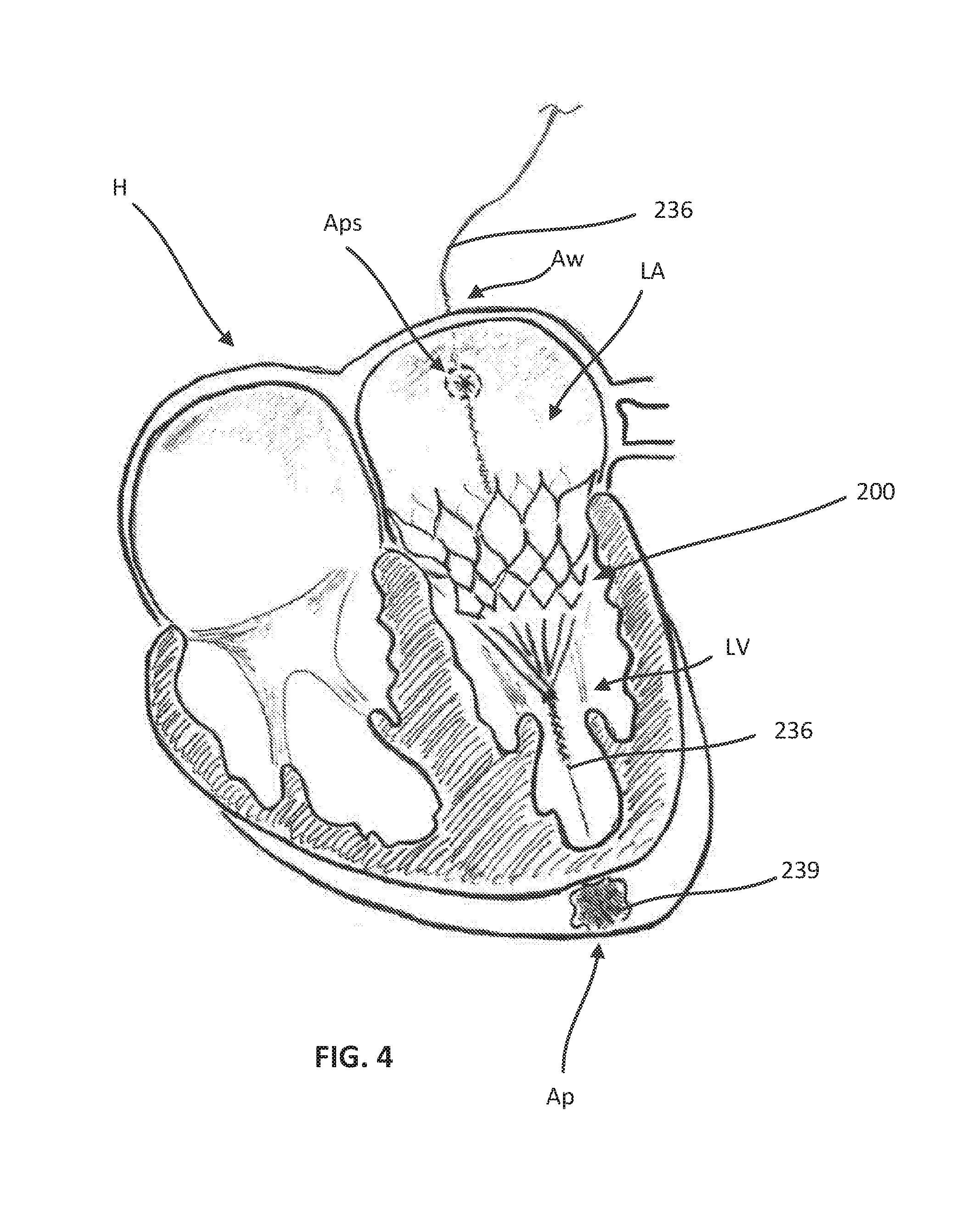
FIGS. 1-6 are each a cross-sectional illustration of a heart with devices used during various stages in a procedure to transatrially deliver and deploy a prosthetic mitral valve, according to an embodiment.
FIGS. 7-9 are each a cross-sectional illustration of a heart with devices used during various stages in a procedure to transatrially deliver and deploy a prosthetic mitral valve, according to another embodiment.
FIGS. 10-12 are front, bottom, and top views of a prosthetic heart valve according to an embodiment.
FIG. 13 is an opened and flattened view of the inner frame of the prosthetic heart valve of FIGS. 10-12, in an unexpanded configuration.
FIGS. 14 and 15 are side and bottom views, respectively, of the inner frame of FIG. 13 in an expanded configuration.
FIG. 16 is an opened and flattened view of the outer frame of the valve of FIGS. 10-12, in an unexpanded configuration.
FIGS. 17 and 18 are side and top views, respectively, of the outer frame of FIG. 16 in an expanded configuration.
FIGS. 19-21 are side, front, and top views of an assembly of the inner frame of FIGS. 13-15 and the outer frame of FIGS. 16-18.
FIG. 22 is a side perspective view of the assembly of the inner frame of FIGS. 13-15 and the outer frame of FIGS. 16-18 shown in a biased expanded configuration.
FIG. 23 is a side perspective view of the assembly of FIG. 19 with the outer frame shown inverted.
FIG. 24 is side view of the assembly of FIG. 23 shown in a collapsed configuration within a lumen of a delivery sheath.
FIG. 25 is a side view of the assembly of FIG. 24 shown in a first partially deployed configuration.
FIG. 26 is a side view of the assembly of FIG. 24 shown in a second partially deployed configuration.
FIG. 27 is a side view of the assembly of FIG. 24 shown in a third partially deployed configuration in which the inverted outer frame is substantially deployed outside of the delivery sheath.
FIG. 28 is a side view of the assembly of FIG. 24 shown in a fourth partially deployed configuration in which the outer frame has reverted and assumed a biased expanded configuration.
FIG. 29 is a side view of a prosthetic mitral valve in a collapsed configuration within a lumen of a portion of a delivery sheath and a balloon dilator device coupled to the delivery sheath.
FIG. 30 is a cross-sectional illustration of a heart with a portion of a delivery sheath shown after deploying a prosthetic mitral valve with the assistance of a wire assist structure, according to an embodiment.
FIG. 31 is a perspective view of the wire assist structure of FIG. 30 coupled to a portion of a prosthetic mitral valve, according to an embodiment.
FIG. 32 is a perspective view of an assist member coupled to a portion of a prosthetic mitral valve, according to an embodiment.
FIG. 33 is a flowchart illustrating a method of delivering a prosthetic mitral valve transatrially, according to an embodiment.
FIG. 34 is a side view of a portion of an epicardial pad device, according to an embodiment, and shown in a collapsed configuration within a delivery sheath.
FIG. 35 is a side perspective view of the epicardial pad device of FIG. 34 shown in an expanded configuration.
FIG. 36 is a side perspective view of a portion of a heart illustrating purse-string sutures at an apex of the heart prior to securing an epicardial pad device thereto.
FIG. 37 is a side perspective view of the epicardial pad device of FIG. 34 shown in the expanded configuration.
FIG. 38 is a bottom perspective view of a portion of a heart illustrating the epicardial pad device of FIG. 34 secured thereto.
FIG. 39 is an enlarged side perspective view and FIG. 40 is an enlarged bottom view of a portion A in FIG. 38 illustrating an integrated locking mechanism.
FIG. 41 is a side view of an epicardial pad device, according to another embodiment, and shown in a collapsed configuration.
FIG. 42 is a side perspective view of the epicardial pad device of FIG. 41 shown in an expanded configuration.
FIG. 43 is a side view of the epicardial device of FIG. 41 shown in the expanded configuration and being deployed near an apex of a heart.
FIG. 44 is a side view of an epicardial pad device, according to another embodiment, and shown in an expanded configuration being deployed near a heart.
FIG. 45 is a side view of the epicardial pad device of FIG. 44 shown in a collapsed configuration and deployed on the apex of the heart.
FIGS. 46 and 47 are each a side view of an epicardial pad device, according to another embodiment, and shown being deployed on an apex of a heart.
FIG. 48 is a bottom view of a heart with the epicardial pad of FIGS. 46 and 47 secured to the apex of the heart.
FIG. 49 is a front view of a portion of a patient's body illustrating an example location for a mini-thoracotomy.
FIGS. 50-55 are each a cross-sectional illustration of a heart with devices used during various stages in a procedure to transjugularly deliver and deploy a prosthetic mitral valve, according to an embodiment.
FIGS. 56-58 are each a cross-sectional illustration of a heart with devices used during various stages in a procedure to transjugularly deliver and deploy a prosthetic mitral valve, according to another embodiment.
FIG. 59 is a front view of a portion of a patient's body illustrating a stage of a transjugular delivery of a prosthetic mitral valve.
DETAILED DESCRIPTION
Apparatus and methods are described herein for use in the delivery and deployment of a prosthetic mitral valve into a heart. As described herein, in some embodiments, a method includes delivering a prosthetic mitral valve into a heart via a transatrial approach, and in some embodiments a method includes delivering a prosthetic mitral valve into a heart via a transjugular approach. In either approach, an outer frame of a prosthetic mitral valve can have a biased expanded configuration and be inverted relative to an inner frame of the prosthetic mitral valve prior to delivery. After inverting the outer frame, the prosthetic mitral valve is inserted into a lumen of an inner delivery sheath such that the mitral valve is moved to a collapsed configuration. The inner delivery sheath is moveably disposed within an introducer sheath and the introducer sheath can be inserted into an opening in a wall of the left atrium of a patient's heart in a transatrial approach, or through the jugular vein in a transjugular approach and through the atrial septum and into the left atrium of the patient. The introducer sheath can be moved between the native mitral valve leaflets (i.e., the mitral valve gap) and through the ventricle and apex of the heart of the patient until a distal end portion of the introducer sheath is disposed outside of and adjacent to the apex of the heart. An epicardial pad device is moved distally out of the introducer sheath and disposed outside of and adjacent to the apex of the heart. The introducer sheath is withdrawn proximally back through the left ventricle, mitral valve gap and a distal end is disposed within the left atrium of the heart. The inner delivery sheath is extended distally relative to the introducer sheath and within the atrium of the heart. The prosthetic mitral valve is then moved distally out of the inner delivery sheath such that the inverted outer frame reverts and the prosthetic mitral valve assumes its biased expanded configuration. The prosthetic mitral valve is then positioned within a mitral annulus of the heart, and tensioned and secured in place using a tether coupled to the epicardial pad device.
Transatrial delivery of the prosthetic mitral valve, and associated components (e.g., epicardial pad and tether), is a desirable delivery approach in many instances. Transatrial delivery, as described below with respect to FIGS. 1-6, for example, can be accomplished using only a single incision (i.e., a single access point) in the patient's body. Limiting the number of body incisions, in this manner, provides for a safer, more repeatable procedure with expedited recovery, while limiting complications and infections during the procedure and recovery of the patient.
Transjugular delivery of the prosthetic mitral valve, and associated components (e.g., epicardial pad and tether), is also a desirable delivery approach in many instances. Transjugular delivery, as described below with respect to FIGS. 50-55, for example, can be accomplished using only a single incision (i.e., a single access point) in the patient's body. Limiting the number of body incisions, in this manner, provides for a safer, more repeatable procedure with expedited recovery, while limiting complications and infections during the procedure and recovery of the patient.
FIGS. 1-6 illustrate a method of delivering a prosthetic mitral valve 200 (shown in FIGS. 3-6) to a left atrium LA of a heart H, e.g., via introduction through a mini-thoracotomy (see FIG. 49). As shown in FIG. 1, a distal end portion of an introducer sheath 226 is inserted through a trans-atrial puncture in an atrial wall Aw of the heart H, extended into the left atrium LA, through a mitral valve gap and into the left ventricle LV, and then through a trans-apical puncture through the ventricular wall at the apex Ap of the heart H. A dilator 235 and a guidewire 234 are moveably disposed within a lumen of the introducer sheath 226 and are used to aid in the insertion and maneuvering of the introducer sheath 226 described above. For example, during delivery of the introducer sheath 226 from the atrial access site through the apex Ap of the heart H, the dilator 235 can extend distally from the distal end portion of the introducer sheath 226 and aid in creating space (e.g., by dilating nearby tissue) through which the introducer sheath 226 can maneuver. The guidewire 234 can be used to guide the introducer sheath 226 along a desired path (i.e., from the atrium to the ventricle and through the apex AP). The prosthetic mitral valve 200 (also referred to herein as "valve") is coupled to or disposed about a tether 236 (see e.g., FIG. 4), and an end portion of the tether 236 is coupled to an epicardial pad device 239, each of which is movably disposed within an inner delivery sheath 264 (see e.g., FIG. 3) which can be movably disposed within the introducer sheath 226 during delivery of the introducer sheath 226.
After the introducer sheath 226 has been extended through the atrial puncture site Aps and the apex Ap of the heart H, the dilator 235 and the guidewire 234 can be pulled or otherwise withdrawn proximally through a proximal end portion of the lumen of the introducer sheath 226, and a pusher device (not shown) can be used to deliver and/or deploy the epicardial pad device 239. The epicardial pad device 239 can be used to secure the tether 236 and the valve 200 in position within the mitral annulus, as described further herein with respect to FIG. 6.
The epicardial pad device 239 can be delivered and/or deployed by pushing with the pusher device (not shown) such that the epicardial pad device 239 and a portion of the tether 236 exit both the distal end portion of the inner delivery sheath 264 (shown in FIG. 3) and the distal end of the introducer sheath 226 and such that the epicardial pad device 239 is disposed outside the heart H, as shown in FIG. 2. For example, an epicardial pad device as described in International Patent Application No. PCT/US14/49218 ("the '218 PCT application"), the disclosure of which is incorporated herein by reference in its entirety, can be used. In some embodiments, an expandable epicardial pad can be used to secure the tether and valve in position. Example embodiments of expandable pads that can be used are described herein with reference to FIGS. 34-48. Such an epicardial pad can be smaller in size such that the pad can be delivered to the heart via a small incision and small catheter or delivery sheath (e.g., the same as or similar to the inner delivery sheath 264, or the same as or similar to the introducer sheath 226). In some embodiments, a positioning device can be used to help position the valve and deploy the epicardial pad device. For example, a positioning device as described in the '218 PCT application incorporated by reference above, or devices described in International Patent Application No. PCT/US14/61046, the disclosure of which is incorporated herein by reference in its entirety, can be used. In some embodiments, rather than securing the prosthetic mitral valve with a tether and epicardial pad, the prosthetic mitral valve can be secured with clips or other coupling methods to a portion(s) of the mitral valve apparatus and/or to the ventricular wall of the heart. For example, such coupling methods are described in International Patent Application No. PCT/US14/58826 ("the '826 PCT application"), the disclosure of which is incorporated herein by reference in its entirety.
After the epicardial pad device 239 is disposed outside the heart, as shown in FIG. 2, the introducer sheath 226 can be withdrawn proximally relative to the inner delivery sheath 264 through the atrial puncture site Aps and outside the heart H. During removal from the heart H of the introducer sheath 226, the inner delivery sheath 264 (with the valve 200 disposed therein) remains in the heart to aid in delivery and deployment of the valve 200.
The valve 200 can be formed with a shape-memory material (as described in more detail below) and can have a biased undeformed shape and can be manipulated and/or deformed (e.g., compressed and/or expanded) and, when released, return to its original undeformed shape. For example, the valve 200 can be in a collapsed or deformed configuration when disposed within the lumen of the inner delivery sheath 264, and can be moved to its biased, expanded or undeformed configuration when delivered from the inner delivery sheath 264 and deployed within the heart H. The valve 200 can be, for example, constructed the same as or similar to, and function the same as or similar to any of the valves described herein (e.g., the valve 500) or in PCT International Application No. PCT/US2015/014572 (referred to herein as "the '572 PCT Application), U.S. Provisional Application No. 62/137,384 (referred to herein as "the '384 Application), and/or U.S. Provisional Application No. 62/187,896 (referred to herein as "the '896 Application), the entire disclosures of which are incorporated herein by reference in their entireties. In some embodiments, actuator wires (not shown) can be used to selectively (e.g., by an operator) assist and/or control expansion, deployment and/or articulation of the valve 200 as the valve 200 is delivered to the heart. For example, actuator wires as described in the '384 Application and/or the '896 Application, both incorporated by reference above, can be used.
To deliver and deploy the valve 200, a pusher device (not shown) movably disposed within the inner delivery sheath 264 can push the valve 200 out of the distal end of the inner delivery sheath 264 and within the left atrium of the heart H, as shown in FIG. 3. Optionally, the inner delivery sheath 264 can also be pulled proximally as the pusher moves the valve 200 distally. As the valve 200 exits the inner delivery sheath 264, the valve 200 can assume its biased expanded or deployed configuration within the left atrium LA. With the valve 200 movably coupled to the tether 236, the pusher can be used to push or move the valve 200 relative to the tether 236 to position the valve 200 within the mitral annulus. Simultaneously, the tether 236 is pulled proximally such that the epicardial pad device 239 is pulled proximally and into contact with the apex Ap of the heart H, and the portion of the tether 236 disposed between the epicardial pad device 239 and the valve 200 is pulled taut. The tether 236 in a taut configuration can aid in movement of the valve 200 as the valve 200 is moved relative to the tether 236 and positioned within the mitral annulus. In some embodiments, the pusher device can also be used to aid in positioning the valve 200 in a desired radial orientation within the left atrium LA. For example, the pusher device can define an internal lumen (not shown) that can be placed over an inner frame portion of the valve 200 to hold the inner frame portion in a small diameter, which can help enable the valve 200 to be positioned in a desired radial orientation and be seated within the annulus of the mitral valve. Further examples of such a valve assist device are described below with reference to FIGS. 30-32.
As shown by progression in FIGS. 5 and 6, and as described above, as the valve 200 is deployed within the left atrium LA of the heart H, the valve 200 is allowed to assume its biased expanded or deployed configuration. The inner delivery sheath 264 can be removed from the patient and the valve 200 can be positioned, secured or locked, and tensioned in a desired position within the mitral annulus. For example, as described above, the valve 200 can be moved relative to the tether 236 to obtain the desired or optimal location in the native mitral annulus and minimize perivalvular leaks, and the tether 236 can be pulled taut. Once the valve 200 is disposed in a desirable position and the tether 236 is desirably tensioned, the valve 200 can be secured or locked relative to the tether 236. The valve 200 can be secured or locked to the tether 236 in any suitable manner such that the valve 200 is prevented from moving or translating about or along the tether 236 during normal heart functioning conditions (e.g., during systole and/or diastole).
For example, a locking mechanism (not shown) can be used to secure the tether 236 to the valve 200. In some embodiments, for example, a locking mechanism can be coupled to or included with the valve 200 and can include a tether attachment member (not shown) that defines at least a portion of a tether passageway (not shown) through which a portion of the tether 236 can be received therethrough. The tether attachment member can further define a locking pin channel that intersects the tether passageway. A locking pin (not shown) is disposable within the locking pin channel and movable between a first position in which the locking pin is at a spaced distance from the tether passageway, and a second position in which the locking pin intersects the tether passageway and can engage the portion of the tether 236 disposed therein to secure the tether to the tether attachment member. In some embodiments, the tether attachment member and the valve 200 can be monolithically constructed, while in other embodiments the tether attachment member and the valve 200 can be formed separately and coupled together. In such embodiments, in some instances, the tether attachment member can be coupled to the valve and then delivered to and deployed within the heart H, while in other instances, the tether attachment member and the valve 200 can be delivered to the heart H together, and can then engage one another to secure or lock the valve to the tether 236. In such instances, the tether attachment member can be configured to be disposed about the tether 236 such that it can translate or move along the tether 236 and be moved into engagement with the valve 200 when the valve is in a desired position and configuration. In some embodiments, a tool (not shown) separate from the locking mechanism can be used to deploy or otherwise cause the locking mechanism to engage the valve 200 and/or the tether 236 for securement. In some instances, the tool can be disposed about the tether 236 and translate or move along the tether 236.
After the valve 200 is deployed, proper tension is achieved between the valve 200 and the epicardial pad device 239, and the valve 200 is secured or locked in position relative to the tether 236, an excess portion (i.e., a proximal portion) of the tether 236 can be cut or otherwise removed from the heart H. As shown in FIG. 5, a tether cutting tool 231 can be used to cut the proximal portion of the tether 236 for removal of the proximal portion from the left atrium LA of the heart H. In some embodiments, the tether cutting tool 231 can define an inner lumen therebetween configured to receive at least a portion of the tether 236 (e.g., the proximal portion of the tether 236). In this manner, the tether cutting tool can be disposed about and translate along the tether 236 until it reaches a desirable position to cut the tether 236. The tether cutting tool 231 can be configured to remove from the heart H the portion of the tether 236 that it cut. Upon cutting and removal of a portion of the tether 236, the valve 200, secured to the tether 236 and the epicardial pad device 239 (disposed outside the heart) as shown in FIG. 6, can remain within and function within the heart H (e.g. to limit or prevent mitral valve regurgitation, as discussed further herein). In some embodiments, the tether cutting tool 231 can, in addition to being configured to cut a portion of the tether 236, be configured to deliver and/or deploy the locking mechanism used to secure the valve 200 to the tether 236.
In other embodiments, instead of delivering and deploying an epicardial pad via the introducer sheath through the left atrium, mitral valve gap and ventricle wall, an epicardial pad can be delivered from outside the heart and to the apex of the heart. For example, similar to the procedure described above with respect to the valve 200, a guide wire and introducer sheath can be routed from the left atrium to the left ventricle of the heart and through the ventricle wall to deliver a distal portion of a tether outside the heart near the apex of the heart. The tether can be coupled to a valve (e.g., valve 200) and inserted through an inner delivery sheath movably disposed with the introducer sheath as described above with respect to valve 200 and FIGS. 1-6. An epicardial pad can be delivered via a separate device different than the introducer sheath to near the apex of the heart. The distal free end of the tether can be threaded through and coupled to the epicardial pad. The introducer sheath can be withdrawn, and the valve can be delivered, deployed, tensioned and secured or locked, as discussed above with respect to the valve 200.
In other embodiments, a snare device can be used to grab or snare the tether to move it from a location within the heart (e.g., from an atrium or a ventricle) through a ventricle wall at or near the apex Ap and outside of the heart H. FIGS. 7-9 illustrate another method of transatrially delivering a prosthetic mitral valve 800 to a left atrium LA of a heart H, e.g., via introduction through a mini-thoracotomy. As with the previous embodiment, a distal end portion of an introducer sheath 826 is inserted through a trans-atrial puncture Aps in an atrial wall Aw of the heart H and extended into the left atrium LA of the heart H. The prosthetic mitral valve 800 (also referred to herein as "valve") is coupled to or disposed about a tether 836, each of which is movably disposed within an inner delivery sheath 864 (see e.g., FIG. 8), which is movably disposed within the introducer sheath 826. As shown in FIG. 7, a distal portion of the tether 836 extends distally from a distal end portion of the lumen of the introducer sheath 826.
A snare device 856, as shown in FIG. 7, can be used to snare or capture the tether 836 within the left ventricle LV of the heart H and pull it out through the ventricular wall at or near the apex Ap of the heart H. A procedure catheter 857 can be used to introduce the snare device 856 into the heart. In use, a distal end of the procedure catheter 857 is inserted through an incision or opening in a ventricular wall of the heart H (e.g., at or near the apex Ap of the heart H) such that the distal end of the procedure catheter 857 is disposed within the left ventricle LV of the heart H. The snare device 856 is moved distally within a lumen of the procedure catheter 857 until a distal end of the snare device 856 is disposed within the left ventricle LV (or within the left atrium if necessary to capture the tether 836). The distal portion of the tether 836 extending from the distal end portion of the lumen of the introducer sheath 826 and the distal portion of the valve 800, disposed within the heart H (e.g., the left atrium, the left ventricle, or a portion therebetween) is snared with the snare device 856, as shown in FIG. 7. The tether 836 is pulled with the snare device 856 through the lumen of the procedure catheter 857 such that the distal end of the tether 836 is pulled out the proximal end of the procedure catheter 857 outside of the heart H. Said another way, a distal end of the tether 836 is threaded through a distal opening defined by the procedure catheter 857, through the lumen defined by the procedure catheter 857 and out a proximal opening defined by the procedure catheter 857. The procedure catheter 857 is removed, leaving the distal portion of the tether 836 extending through the incision in the ventricular wall and outside the heart H, as shown in FIG. 8.
The valve 800 can be formed with a shape-memory material (as described in more detail herein) and can have a biased undeformed shape and can be manipulated and/or deformed (e.g., compressed and/or expanded) and, when released, return to its original undeformed shape. For example, the valve 800 can be in a collapsed or deformed configuration when disposed within the lumen of the delivery sheath 864, and can be moved to its biased, expanded or undeformed configuration when delivered from the delivery sheath 864 and deployed within the heart H. The valve 800 can be, for example, constructed the same as or similar to, and function the same as or similar to any of the valves described herein (e.g., the valve 200, the valve 500) or in the '572 PCT Application, the '384 Application, and/or the '896 Application, incorporated herein by reference above. In some embodiments, actuator wires (not shown) can be used to selectively (e.g., by an operator) assist and/or control expansion, deployment and/or articulation of the valve 800 as the valve 800 is delivered to the heart H. For example, actuator wires as described in the '384 Application and/or the '896 Application, both incorporated by reference above, can be used.
To deliver and deploy the valve 800, the delivery sheath 864 can be pulled proximally towards and through the atrial puncture site Aps such that the valve 800, which remains coupled or disposed about the tether 836, exits the distal end portion of the delivery sheath 864 (as shown by progression in FIGS. 8 and 9) and remains in the left atrium LA of the heart H, as shown in FIG. 9. As the valve 800 is deployed within the left atrium LA of the heart H, the valve 800 is allowed to assume its biased expanded or deployed configuration. Alternatively, or additionally, a pusher device (not shown) can be used to push the valve 800 outside of the distal end portion of the delivery sheath 864. In some instances, for example, the pusher device can be used to push the valve 800 while the delivery sheath 864 is pulled and removed from the valve 800. In other words, the valve 800 can be delivered and deployed by pushing the valve 800 with the pusher device, by pulling the inner delivery sheath 864, or both. The tether 836, coupled to the valve 800, can also be used during the deployment of the valve 800. For example, to position the valve 800 within the native mitral annulus, the tether 236 can be pulled proximally after or simultaneously with the pusher device pushing the valve 800 outside the lumen of the delivery sheath 864. The pusher device can also be used to aid in positioning the valve 800 in a desired radial orientation within the left atrium LA. For example, the pusher device can define an internal lumen (not shown) that can be placed over an inner frame portion of the valve 800 to hold the inner frame portion in a small diameter, which can help enable the valve 800 to be positioned in a desired radial orientation and be seated within the annulus of the mitral valve. Further examples of such a valve assist device are described below with reference to FIGS. 30-32.
After the valve 800 is deployed within the left atrium LA, the delivery sheath 864 can be removed from the patient, and the valve 800 can be positioned within the mitral annulus as described above using the tether 836 and/or pusher device. With the valve 800 in a desired position within the mitral annulus, the tension on the tether 836 between the prosthetic mitral valve 800 and the incision at the apex Ap of the heart H can be adjusted and the tether 836 can be secured at the apex Ap on the ventricular wall of the heart H with epicardial pad device 839. For example, with the tether 836 extending outside of the heart, the tether 836 can be threaded through a center opening of the epicardial pad device 839 and through a lumen of an epicardial pad delivery catheter (not shown) (also referred to herein as "pad catheter") such that the epicardial pad 839 is disposed at a distal end of the pad catheter. An outer delivery device 896 can be laced over the pad delivery catheter to collapse the epicardial pad device 839. The outer delivery catheter 896 (with the epicardial pad 839 and pad catheter disposed therein) can have a relatively small outer diameter such that it can be inserted through a small incision in the skin of a patient. When the distal end of the outer delivery catheter 896 is at a desired location near the apex Ap of the heart H, the epicardial pad device 839 can be moved outside of the outer delivery catheter 896 such that the epicardial pad 839 can assume a biased expanded configuration, as shown in FIG. 9.
To move the epicardial pad device 839 outside of the lumen of the outer delivery catheter 896, the pad catheter can be moved distally within the outer delivery catheter 896 to push the epicardial pad device 839 out of the lumen of the outer delivery catheter 896. In an alternative embodiment, the epicardial pad device 839, rather than using a pad catheter as described above, the tether 836 can be threaded through the outer delivery catheter 896 and the outer delivery catheter 896 can collapse the epicardial pad device 839 within the lumen of the outer delivery catheter 896. The outer delivery catheter 896 be positioned near the apex Ap as described above, and a push rod (not shown) or an inner sheath (not shown) can be used to move the epicardial pad device 839 distally outside of the lumen of the outer delivery catheter 896.
Prior to moving the epicardial pad device 839 into position on the apex Ap of the heart H, conventional purse string sutures (not shown) at the incision through which the tether 836 extends out of the heart H at the apex Ap of the heart H can be closed. The epicardial pad device 839 can then be positioned on the apex Ap of the heart, as shown in FIG. 9.
Although as described above the snare device 856 is introduced into the heart H via the procedure catheter 857, and the epicardial pad device 839 is delivered to the apex Ap of the heart H via the outer delivery catheter 896, in other embodiments, both a snare device and an epicardial pad device can be introduced or delivered via the same catheter, e.g., the procedure catheter 857. In such embodiments, after use of the snaring device to snare the tether and removal from the heart of the snaring device via the procedure catheter, the epicardial pad device and pad catheter described above can be inserted or loaded into the procedure catheter. Similarly, in some embodiments, the distal end of the tether can be threaded through the center opening of the epicardial pad device and through the lumen defined by the procedure catheter (rather than the pad catheter). The epicardial pad device can then be delivered and deployed as discussed above with respect to FIGS. 8 and 9.
Various different types and/or configurations of an epicardial pad device can be used to anchor the prosthetic mitral valve 800 as described above. For example, any of the epicardial anchor devices described herein, in the '218 PCT application incorporated by reference above, and/or in U.S. Provisional Application No. 62/212,803, can be used. For example, an epicardial pad device can include a frame member (not shown) and a fabric cover (not shown). The frame member can be formed with, for example, a shape-memory material such as Nitinol.RTM. such that the epicardial pad can have a biased expanded configuration, and can be moved to a collapsed configuration. For example, the epicardial pad can be placed within a lumen of a delivery sheath (e.g., pad catheter 896) to move the epicardial pad device to the collapsed configuration. During delivery, the epicardial pad can be moved outside of the delivery sheath, as discussed above with respect to FIGS. 8 and 9, such that the epicardial pad can assume its biased expanded configuration. The fabric cover can be formed with various suitable material(s) such as, for example, polyester, polyethylene or ePTFE.
In an alternative, the valve 800 can be coupled to the tether 836 such that the valve 800 is movable or can translate relative to the tether 836 as described above for valve 200. In such an embodiment, a locking mechanism (not shown) can be used to secure the tether 836 to the valve 800 as described above for valve 200. In such an embodiment, a snare device can be used to pull the tether 836 through the wall of the left ventricle and out of the heart and an epicardial pad can be attached to the tether 836 as described above, however adjustment and securement of the valve would be performed in a similar or same manner as described for valve 200. For example, the valve 800 can be translated relative to the tether 836 to position the valve in the mitral annulus and the locking mechanism can be used to secure the valve 800 to the tether 836 as previously described for valve 200. For example, the locking mechanism can include a tether attachment member (not shown) that defines at least a portion of a tether passageway (not shown) through which a portion of the tether 836 can be received therethrough. The tether attachment member further defines a locking pin channel that intersects the tether passageway. A locking pin (not shown) is disposable within the locking pin channel and movable between a first position in which the locking pin is at a spaced distance from the tether passageway, and a second position in which the locking pin intersects the tether passageway and can engage the portion of the tether 836 disposed therein to secure the tether to the tether attachment member. In some embodiments, the tether attachment member and the valve 800 can be monolithically constructed, while in other embodiments the tether attachment member and the valve 800 can be formed separately and coupled together. In such embodiments, in some instances, the tether attachment member can be coupled to the valve and then delivered to and deployed within the heart H, while in other instances, the tether attachment member and the valve 800 can be delivered to the heart H, and can then engage one another to secure or lock the valve to the tether 836. In such instances, the tether attachment member can be configured to be disposed about the tether 836 such that it can translate or move along the tether 836 and engage with the valve 800 when the valve is in its desirable position and configuration. In some embodiments, a tool (not shown) separate from the locking mechanism can be used to deploy or otherwise cause the locking mechanism to engage the valve 800 and/or the tether 836 for securement. In some instances, the tool can be disposed about the tether 836 and translate or move along the tether 836.
After the valve 800 is deployed, proper tension is achieved between the valve 800 and the epicardial pad device 839, and the valve 800 is secured or locked in position relative to the tether 836, an excess portion (i.e., a proximal portion) of the tether 836 can be cut or otherwise removed from the heart H, similar to as described above with respect to FIG. 5. For example, a tether cutting tool (not shown) can be used to cut the proximal portion of the tether 836 for removal of the proximal portion from the left atrium LA of the heart H. In some embodiments, the tether cutting tool can define an inner lumen therebetween configured to receive at least a portion of the tether 836 (e.g., the proximal portion of the tether 836). In this manner, the tether cutting tool can be disposed about and translate along the tether 836 until it reaches a desirable position to cut the tether 836. The tether cutting tool can be configured to remove from the heart H the portion of the tether 836 that it cut. Upon cutting and removal of a portion of the tether 836, the valve 800, secured to the tether 836 and the epicardial pad device 839 (disposed outside the heart) as shown in FIG. 9, can remain within and function in a desirable fashion within the heart H (e.g. to limit or prevent mitral valve regurgitation, as discussed further herein). In some embodiments, the tether cutting tool can, in addition to be configured to cut a portion of the tether 836, be configured to deliver and/or deploy the locking mechanism.
FIGS. 10-12 illustrate an embodiment of a prosthetic heart valve that can be delivered and deployed within a left atrium of a heart using a transatrial delivery approach as described above. FIGS. 10-12 are front, bottom, and top views, respectively, of a prosthetic heart valve 500 according to an embodiment. Prosthetic heart valve 500 (also referred to herein as "valve") is designed to replace a damaged or diseased native heart valve such as a mitral valve. Valve 500 includes an outer frame assembly 510 and an inner valve assembly 540 coupled to the outer frame assembly 510.
As shown, outer frame assembly 510 includes an outer frame 520, covered on all or a portion of its outer face with an outer covering 530, and covered on all or a portion of its inner face by an inner covering 532. Outer frame 520 can provide several functions for prosthetic heart valve 500, including serving as the primary structure, as an anchoring mechanism and/or an attachment point for a separate anchoring mechanism to anchor the valve to the native heart valve apparatus, a support to carry inner valve assembly 540, and/or a seal to inhibit paravalvular leakage between prosthetic heart valve 500 and the native heart valve apparatus.
Outer frame 520 is configured to be manipulated and/or deformed (e.g., compressed and/or expanded) and, when released, return to its original (undeformed) shape. To achieve this, outer frame 520 can be formed of materials, such as metals or plastics, that have shape memory properties. With regards to metals, Nitinol.RTM. has been found to be especially useful since it can be processed to be austenitic, martensitic or super elastic. Other shape memory alloys, such as Cu--Zn--Al--Ni alloys, and Cu--Al--Ni alloys, may also be used.
As best shown in FIG. 10, outer frame assembly 510 has an upper end (e.g., at the atrium portion 516), a lower end (e.g., at the ventricle portion 512), and a medial portion (e.g., at the annulus portion 514) therebetween. The medial portion of the outer frame assembly 510 has a perimeter that is configured (e.g., sized, shaped) to fit into an annulus of a native atrioventricular valve. The upper end of the outer frame assembly 510 has a perimeter that is larger than the perimeter of the medial portion. In some embodiments, the perimeter of the upper end of the outer frame assembly 510 has a perimeter that is substantially larger than the perimeter of the medial portion. As shown best in FIG. 12, the upper end and the medial portion of the outer frame assembly 510 has a D-shaped cross-section. In this manner, the outer frame assembly 510 promotes a suitable fit into the annulus of the native atrioventricular valve.
Inner valve assembly 540 includes an inner frame 550, an outer covering 560, and leaflets 570. As shown, the inner valve assembly 540 includes an upper portion having a periphery formed with multiple arches. The inner frame 550 includes six axial posts or frame members that support outer covering 560 and leaflets 570. Leaflets 570 are attached along three of the posts, shown as commissure posts 552 (best illustrated in FIG. 11), and outer covering 560 is attached to the other three posts, 554 (best illustrated in FIG. 11), and optionally to commissure posts 552. Each of outer covering 560 and leaflets 570 are formed of approximately rectangular sheets of material, which are joined together at their upper, or atrium end. The lower, ventricle end of outer covering 560 may be joined to inner covering 532 of outer frame assembly 510, and the lower, ventricle end of leaflets 570 may form free edges 575, though coupled to the lower ends of commissure posts 552.
Although inner valve assembly 540 is shown as having three leaflets, in other embodiments, an inner valve assembly can include any suitable number of leaflets. The leaflets 570 are movable between an open configuration and a closed configuration in which the leaflets 570 coapt, or meet in a sealing abutment.
Outer covering 530 of the outer frame assembly 510 and inner covering 532 of outer frame assembly 510, outer covering 560 of the inner valve assembly 540 and leaflets 570 of the inner valve assembly 540 may be formed of any suitable material, or combination of materials, such as those discussed above. In this embodiment, the inner covering 532 of the outer frame assembly 510, the outer covering 560 of the inner valve assembly 540, and the leaflets 570 of the inner valve assembly 540 are formed, at least in part, of porcine pericardium. Moreover, in this embodiment, the outer covering 530 of the outer frame assembly 510 is formed, at least in part, of polyester.
Inner frame 550 is shown in more detail in FIGS. 13-15. Specifically, FIGS. 13-15 show inner frame 550 in an undeformed, initial state (FIG. 13), a side view of the inner frame 550 in a deployed configuration (FIG. 14), and a bottom view of the inner frame 550 in a deployed configuration (FIG. 15), respectively, according to an embodiment.
In this embodiment, inner frame 550 is formed from a laser-cut tube of Nitinol.RTM.. Inner frame 550 is illustrated in FIG. 13 in an undeformed, initial state, i.e. as laser-cut, but cut and unrolled into a flat sheet for ease of illustration. Inner frame 550 can be divided into four portions, corresponding to functionally different portions of the inner frame 550 in final form: atrial portion 541, body portion 542, strut portion 543, and tether clamp or connecting portion 544. Strut portion 543 includes six struts, such as strut 543A, which connect body portion 542 to tether clamp portion 544.
Connecting portion 544 includes longitudinal extensions of the struts, connected circumferentially by pairs of opposed, slightly V-shaped connecting members (or "micro-Vs"). Connecting portion 544 is configured to be radially collapsed by application of a compressive force, which causes the micro-Vs to become more deeply V-shaped, with the vertices moving closer together longitudinally and the open ends of the V shapes moving closer together circumferentially. Thus, connecting portion 544 can be configured to compressively clamp or grip one end of a tether, either connecting directly onto a tether line (e.g. braided filament line) or onto an intermediate structure, such as a polymer or metal piece that is in term firmly fixed to the tether line.
In contrast to connecting portion 544, atrial portion 541 and body portion 542 are configured to be expanded radially. Strut portion 543 forms a longitudinal connection, and radial transition, between the expanded body portion and the compressed connecting portion 544.
Body portion 542 includes six longitudinal posts, such as post 542A. The posts can be used to attach leaflets 570 to inner frame 540, and/or can be used to attach inner assembly 540 to outer assembly 510, such as by connecting inner frame 550 to outer frame 520. In the illustrated embodiment, the posts include openings through which connecting members (such as suture filaments and/or wires) can be passed to couple the posts to other structures.
Inner frame 550 is shown in a fully deformed, i.e. the final, deployed configuration, in side view and bottom view in FIGS. 14 and 15, respectively.
Outer frame 520 of valve 500 is shown in more detail in FIGS. 16-18. In this embodiment, outer frame 520 is also formed from a laser-cut tube of Nitinol.RTM.. Outer frame 520 is illustrated in FIG. 16 in an undeformed, initial state, i.e. as laser-cut, but cut and unrolled into a flat sheet for ease of illustration. Outer frame 520 can be divided into a coupling portion 571, a body portion 572, and a cuff portion 573, as shown in FIG. 16. Coupling portion 571 includes multiple openings or apertures, such as 571A, by which outer frame 520 can be coupled to inner frame 550, as discussed in more detail below.
Outer frame 520 is shown in a fully deformed, i.e. the final, deployed configuration, in side view and top view in FIGS. 17 and 18, respectively. As best seen in FIG. 18, the lower end of coupling portion 571 forms a roughly circular opening (identified by "O" in FIG. 18). The diameter of this opening preferably corresponds approximately to the diameter of body portion 542 of inner frame 550, to facilitate coupling of the two components of valve 500.
Outer frame 520 and inner frame 550 are shown coupled together in FIGS. 19-21, in front, side, and top views, respectively. The two frames collectively form a structural support for a prosthetic valve such as valve 500. The frames support the valve leaflet structure (e.g., leaflets 570) in the desired relationship to the native valve annulus, support the coverings (e.g., outer covering 530, inner covering 532, outer covering 560) for the two frames to provide a barrier to blood leakage between the atrium and ventricle, and couple to the tether (e.g., tether assembly 590) (by the inner frame 550) to aid in holding the prosthetic valve in place in the native valve annulus by the tether connection to the ventricle wall. The outer frame 520 and the inner frame 550 are connected at six coupling points (representative points are identified as "C"). In this embodiment, the coupling points are implemented with a mechanical fastener, such as a short length of wire, passed through an aperture (such as aperture 571A) in coupling portion 571 of outer frame 520 and corresponding openings in longitudinal posts (such as post 542A) in body portion 542 of inner frame 550. Inner frame 550 is thus disposed within the outer frame 520 and securely coupled to it.
FIGS. 22-28 illustrate a method of reconfiguring a prosthetic heart valve 300 (e.g., prosthetic mitral valve) prior to inserting the prosthetic heart valve 300 into a delivery sheath 326 (see, e.g., FIGS. 24-28) for delivery into the heart via an access point in the atrium (e.g., the left atrium). The prosthetic heart valve 300 (also referred to herein as "valve") can be constructed the same as or similar to, and function the same as or similar to the valve 500 described above. Thus, some details regarding the valve 300 are not described below. It should be understood that for features and functions not specifically discussed, those features and functions can be the same as or similar to the valve 500.
As shown in FIG. 22, the valve 300 has an outer frame 320 and an inner frame 350. As discussed above for valves 200 and 500, the outer frame 320 and the inner frame 350 of valve 300 can each be formed with a shape-memory material and have a biased expanded or deployed configuration. The outer frame 320 and the inner frame 350 can be moved to a collapsed or undeployed configuration for delivery of the valve 300 to the heart. In this example method of preparing the valve 300 for delivery to the heart, the outer frame 320 of the valve 300 is first disposed in a prolapsed or inverted configuration as shown in FIG. 23. Specifically, the elastic or superelastic structure of outer frame 320 of valve 300 allows the outer frame 320 to be disposed in the prolapsed or inverted configuration prior to the valve 300 being inserted into the lumen of the delivery sheath 326. As shown in FIG. 23, to dispose the outer frame 320 in the inverted configuration, the outer frame 320 is folded or inverted distally such that the outer frame 320 is pointed away from the inner frame 350. In this inverted configuration, the overall outer perimeter or outer diameter of the valve 300 is reduced and the overall length is increased. For example, the diameter D1 shown in FIG. 22 is greater than the diameter D2 shown in FIG. 23, and the length L1 in FIG. 19 is less than the length L2 in FIG. 23. With the outer frame 320 in the inverted configuration, the valve 300 can be placed within a lumen of a delivery sheath 326 as shown in FIG. 24 for delivery of the valve 300 to the left atrium of the heart. By disposing the outer frame 320 in the inverted configuration, the valve 300 can be collapsed into a smaller overall diameter, i.e. placed in a smaller diameter delivery sheath, than would be possible if the valve 300 in the configuration shown in FIG. 22 were collapsed radially. This is because in the configuration shown in FIG. 22, the two frames are concentric, and thus the outer frame 320 must be collapsed around the inner frame 350, whereas in the configuration shown in FIG. 23, the two frames are coaxial but not concentric, such that the outer frame 320 can be collapsed without needing to accommodate the inner frame 350 inside it.
The procedure to deliver the valve 300 to the heart can be the same as or similar to the procedures described with reference to FIGS. 1-9. With the distal end portion of the delivery sheath 326 disposed within the left atrium of the heart, the valve 300 can be deployed outside of the delivery sheath 326. For example, although not shown, a tether such as tether 236 described above for the valve 200 can be attached to the valve 300, and a pusher device (not shown) can be used to push the valve distally along the tether and deploy the valve 300. Thus, as described above for valve 200, the valve 300 can be deployed by pushing with the pusher device, pulling with the tether, or both.
As the valve 300 exits the lumen of the delivery sheath 326, the outer frame assembly 310 exits first in its inverted configuration as shown in the progression of FIGS. 25-27. After the outer frame assembly 310 is fully outside of the lumen of the delivery sheath 326, the outer frame 320 can revert to its expanded or deployed configuration as shown in FIG. 28. In some embodiments, the pusher device and/or the tether can be used to aid in the reversion of the outer frame assembly 310. The valve 300 can continue to be deployed until the inner frame 350 is fully deployed with the left atrium and the valve 300 is in the expanded or deployed configuration (as shown in FIG. 22).
In some embodiments, a balloon dilator device can be used during a procedure for transatrial delivery of a prosthetic heart valve to the heart. For example, a balloon dilator as described in International Patent Application No. PCT/US15/14572 ("the '572 PCT application"), the disclosure of which is incorporated herein by reference in its entirety, can be used (e.g., the same as or similar to the balloon dilator device 445). FIG. 29 illustrates such an optional balloon dilator device that can be used during a procedure for transatrial delivery of a prosthetic heart valve to the heart. FIG. 29 illustrates a valve 400 disposed within a lumen of a delivery sheath 426. The valve 400 can be constructed the same as or similar to, and function the same as or similar to, the valves 200, 500 and 300 described above. For example, the valve 400 can include an outer frame 420 and an inner frame 450 as described above for previous embodiments. A tether 436 can be coupled to the valve 400.
The balloon dilator device 445 includes a balloon member 446 that can be disposed at least partially within the distal end portion of the lumen of the delivery device 426, and distal of the valve 400, as shown in FIG. 29. The balloon dilator device 445 also includes an elongate member 447 coupled to the balloon member 446 and that defines an inflation lumen in fluid communication with an interior of the balloon member 446. The elongate member 447 can be coupled to a source of an inflation medium (not shown) configured to supply the inflation medium to the balloon member 446. With the balloon dilator device 445 coupled to the delivery sheath 426 as shown in FIG. 29, the balloon member 446 can be inflated. The delivery sheath 426 can then be inserted into the left atrium LA. The balloon member 446 provides a smooth surface to aid in maneuvering the delivery sheath 426 through an opening in the left atrium LA and into the heart. With the distal end portion of the delivery sheath 426 disposed within the left atrium LA, the balloon member 446 can be deflated and removed through the apical access site. The valve 400 can then be deployed and positioned within the mitral annulus as described above for FIGS. 1-9. For example, a pusher device 438 (see FIG. 29) can be used to push the valve 400 out of the lumen of the delivery sheath 426 and/or the tether 436 coupled to the valve 400 can be pulled.
FIGS. 30 and 31 illustrate an optional wire assist structure that can be used during a procedure to deliver a prosthetic heart valve transatrially as described above for previous embodiments. A wire assist structure 649 can be releasably coupled to a valve 600 as shown in FIG. 30. The valve 600 can be constructed the same as or similar to, and function the same as or similar to, the valves described above for previous embodiments. For example, the valve 600 can include an outer frame 620 and an inner frame 650. The wire assist structure 649 can be releasably coupled to the inner frame 650 as best shown in FIG. 31. For example, releasable connectors (not shown) can be used to couple the wire assist structure 649 to the inner frame 650.
In use, the wire assist structure 649 can be movably disposed within a delivery sheath 626 used to deliver the valve 600 to the heart. The wire assist structure 649 can hold the inner frame 650 and allow for positioning control of the valve 600 (i.e., clocking and advancement) while the outer frame 650 of the valve 600 is fully expanded, which allows the valve 600 to be functioning during the positioning phase. When the valve 600 is in the desired final position, the wire assist structure 649 can be released from the inner frame 650 and removed with the delivery sheath 626.
FIG. 32 illustrates another optional assist member that can be used during a procedure to deliver a prosthetic heart valve transatrially. An assist member 748 can be in the form of a tubular member defining a lumen with a diameter sized to receive at least a portion of the inner frame 750 of a valve 700. The valve 700 can be constructed the same as or similar to, and function the same as or similar to, the valves described above for previous embodiments. For example, the valve 700 can include an outer frame (not shown) and the inner frame 750 as described above for previous embodiments.
In use, the assist member 748 can be movably disposed within a delivery sheath (not shown) used to deliver the valve 700 and be disposed over at least a portion of the inner valve assembly 740. As with the wire assist structure 649, the assist member 748 can hold the inner frame 750 in a small compact configuration and allow for positioning control of the valve 700 (i.e., clocking and advancement) while the outer frame of the valve 700 is being expanded. This can in some cases allow the valve 700 to be functioning (or at least partially functioning) during the positioning phase of the valve 700. With the inner frame 750 held in a compact or small diameter form factor, the valve 700 can be more easily positioned to help seal the annulus with the outer frame (not shown) of the valve 700. When the valve 700 is in the desired final position, the assist member 748 can be removed.
FIG. 33 is a flowchart illustrating a method of deploying a prosthetic mitral valve to a heart using a transatrial delivery approach. The method includes at 880, disposing an outer frame of a prosthetic mitral valve in its inverted configuration. For example, the prosthetic mitral valve can be formed with a shape-memory material and have a biased expanded configuration. At 882, inserting the prosthetic mitral valve and tether into a lumen of a delivery sheath such that the prosthetic mitral valve is moved to a collapsed configuration. At 884, inserting a catheter through an apex of a heart of a patient and positioning a distal end of the catheter within a left ventricle of the heart. At 886, inserting the delivery sheath with the valve and tether into a left atrium, through a native mitral valve gap of the heart, and positioning a distal end of the delivery sheath within the left ventricle of the heart. At 888, capturing a distal end portion of the tether with a snare and pulling the tether through a lumen of the catheter and out a ventricle wall at the apex of the heart. At 890, deploying the prosthetic mitral valve into the left atrium of the heart such that the mitral valve reverts and assumes its biased expanded configuration. At 892, the prosthetic mitral valve is positioned within a mitral annulus of the heart and optionally an epicardial pad device can be secured to the apex of the heart to maintain the prosthetic mitral valve in the desired position (e.g., orientation) within the mitral annulus. In some embodiments, rather than securing the prosthetic mitral valve with a tether and epicardial pad, the prosthetic mitral valve can be secured with clips or other coupling methods to a portion(s) of the ventricular wall of the heart.
FIGS. 34-38 illustrate an embodiment of an expandable epicardial pad device that can be used to secure a tether attached to a prosthetic mitral valve to the heart, for example, at the apex of the heart. An epicardial pad device 939 (also referred to herein as "epicardial pad" or "pad") can be used, for example, during a procedure to deliver a prosthetic heart valve transatrially as described herein. The epicardial pad 939 can be formed with a small profile such that the epicardial pad 939 can be delivered to the exterior of the heart via a small incision and a small diameter delivery catheter or sheath 963 (see FIGS. 34 and 35). In some embodiments, the delivery sheath 963 can have a diameter, for example, in the range of 3-5 mm. An inner delivery sheath 964 can be movably disposed within a lumen of the delivery sheath 963 and used to hold the tether 936 while the epicardial pad 939 is being deployed as described in more detail below.
As shown in FIGS. 34 and 35 the epicardial pad 939 includes a frame member 961 and a fabric cover 962. The frame member 961 can be formed with, for example a shape-memory material such as Nitinol.RTM. such that the epicardial pad 939 can have a biased expanded configuration as shown in FIGS. 35 and 37, and can be moved to a collapsed configuration as shown in FIG. 34. For example, as shown in FIG. 34 the epicardial pad 939 can be placed within a lumen of the delivery sheath 963 to move the epicardial pad 939 to the collapsed configuration. The fabric cover 962 can be formed with various suitable material(s) such as, for example, polyester, polyethylene or ePTFE.
In use, after a prosthetic mitral valve has been deployed within the heart H via a transatrial delivery approach as described herein, the tether 936 attached the prosthetic valve (not shown) can extend outside the apex of the heart. The epicardial pad 939 can be used to secure the tether 936 and prosthetic valve in a desired position. With the tether 936 extending outside of the heart, the tether 936 can be threaded through a center opening of the epicardial pad 939 and through a lumen of the inner delivery sheath 964, as shown in FIGS. 34 and 35. The outer delivery sheath 963 can be laced over the inner delivery sheath 964 and the epicardial pad 939 to collapse the epicardial pad 939 as shown in FIG. 34. As described above, the outer delivery sheath 964 can have a relatively small outer diameter such that it can be inserted through a small incision in the skin of the patient. When the distal end of the delivery sheath 963 is at a desired location near the apex of the heart, the epicardial pad 939 can be moved outside of the delivery sheath 963 such that the epicardial pad 939 can assume its biased expanded configuration as shown in FIGS. 35 and 37. For example, to move the epicardial pad 939 outside of the lumen of the delivery sheath 963, the delivery sheath 963 can be moved proximally, such that the delivery sheath 963 is removed from epicardial pad 939. Alternatively, the epicardial pad 939 can be moved distally outside of the lumen of the delivery sheath 963. For example, a push rod (not shown) can be used, or the inner delivery sheath 964 in which the tether 936 is disposed can be used to move or push the epicardial pad 939 out of the delivery sheath 963.
Prior to moving the expanded epicardial pad 939 into position on the apex of the heart, conventional purse string sutures 965 at the incision through which the tether 936 extends out of the heart at the apex of the heart can be closed. The epicardial pad 939, in the expanded configuration, can then be positioned on the apex of the heart. In this embodiment, the epicardial pad 939 includes an integral locking mechanism 966 as shown in FIGS. 38-40. The locking mechanism can be formed integrally with the frame member 961 and can include barbs 967. As shown in FIGS. 34 and 35, the tether 936 can be inserted through a lumen of the inner delivery sheath 964 such that the delivery sheath 964 can prevent the barbs 967 from contacting the tether 936. For example, the tether 936 can be threaded into the inner delivery sheath 964 prior to the inner delivery sheath 964 and tether 936 being inserted through the center opening of the epicardial pad 939. Thus, the inner delivery sheath 964 can protect the tether 936 from the barbs 967 of the locking mechanism 966 during deployment of the epicardial pad 939. When the epicardial pad 939 is deployed at the desired position on the heart, the inner delivery sheath 964 can be removed uncovering the tether 936 and allowing the barbs 967 to engage or pierce the tether 936 as shown in FIGS. 39 and 40. The barbs 968 can hold or lock the tether 936 and epicardial pad 939 in the desired position. The barbs 9678 can be oriented at various different angles relative to a longitudinal axis of the epicardial pad 939, such as, for example, between 45-120 degrees.
In alternative embodiments, other methods of securing the epicardial pad 939 to the heart can be used. For example, in an embodiment in which the epicardial pad 939 does not include an integrated locking mechanism as described above, the distal end portion of the tether 936 can be tied or another securing device such as a clip or locking pin can be used.
FIGS. 41-43 illustrate another embodiment of an expandable epicardial pad device that can be used to secure a tether attached to a prosthetic mitral valve to the heart, for example, at the apex of the heart. An epicardial pad device 1039 (also referred to herein as "epicardial pad" or "pad") can be used, for example, during a procedure to deliver a prosthetic heart valve transatrially as described herein. The epicardial pad 1039 can be formed with a small profile such that the epicardial pad 1039 can be delivered to the exterior of the heart via a small incision and a small diameter delivery catheter or sheath (not shown) as described above for epicardial pad 939.
As shown in FIGS. 41-43, the epicardial pad 1039 includes a frame member 1061 and a fabric cover 1062. In this embodiment, the frame member 1061 includes a first frame portion 1068 and a second frame portion 1069. As with the previous embodiment, the frame member 1061 can be formed with, for example a shape-memory material such as Nitinol.RTM., such that the epicardial pad 1039 can have a biased expanded configuration as shown in FIGS. 42 and 43, and can be moved to a collapsed configuration as shown in FIG. 41. For example, although not shown for this embodiment, the epicardial pad 1039 can be placed within a lumen of a delivery sheath to collapse or move the epicardial pad 1039 to the collapsed configuration. In the expanded configuration, the second frame portion 1069 expands within an interior region defined by the first frame portion 1068 as best shown in FIG. 42. In other words, the second frame portion 1069 and the first frame portion 1068 form a double-layer flower-like shape. The fabric cover 1062 can be formed with, for example, various suitable material(s) such as, for example, polyester, polyethylene or ePTFE, as described above for fabric cover 962.
In use, after a prosthetic mitral valve has been deployed within the heart H (FIG. 43), for example, via a transatrial delivery approach as described herein, the tether 1036 attached the prosthetic valve (not shown) can extend outside the apex of the heart. The epicardial pad 1039 can be used to secure the tether 1036 and prosthetic valve in a desired position. With the tether 1036 extending outside of the heart, the tether 1036 can be threaded through a lumen of an inner delivery sheath, such as inner delivery sheath 964 described above, and through a center opening of the epicardial pad 1039. An outer delivery sheath (not shown) can be placed over the inner delivery sheath to collapse the epicardial pad 1039. As described above, the outer delivery sheath can have a relatively small outer diameter such that it can be inserted through a small incision in the skin of the patient. When the distal end of the delivery sheath is at a desired location near the apex of the heart, the epicardial pad 1039 can be moved outside of the delivery sheath 963 such that the epicardial pad 1039 can assume its biased expanded configuration as shown in FIGS. 42 and 43 as described above for epicardial pad 939.
Prior to moving the expanded epicardial pad 1039 into position on the apex of the heart, conventional purse string sutures 1065 at the incision through which the tether 1036 extends out of the heart at the apex of the heart can be closed. The epicardial pad 1039, in the expanded configuration, can then be positioned on the apex of the heart. The epicardial pad 1039 can include an integral locking mechanism, similar to or the same as locking mechanism 966 described above to secure or lock the tether 1036 and epicardial pad 1039 in position on the heart. In alternative embodiments, other methods of securing the epicardial pad 1039 to the heart can be used. For example, as described above, the distal end portion of the tether 1036 can be tied or another securing device such as a clip or locking pin can be used.
FIGS. 44 and 45 illustrate an expandable epicardial pad device 1139 according to another embodiment. The epicardial pad device 1139 can be used in the same or similar manner as described for previous embodiments to secure a tether attached to a prosthetic mitral valve to the heart, for example, at the apex of the heart. The epicardial pad device 1139 (also referred to herein as "epicardial pad" or "pad") can be used, for example, during a procedure to deliver a prosthetic heart valve transatrially as described herein. In this embodiment, the epicardial pad device 1139 includes a balloon member 1155. The balloon member 1155 can be small in size such that the balloon member 1155 can be delivered to the exterior of the heart via a small incision and a small diameter delivery catheter or sheath (not shown) as described above for previous embodiments.
The balloon member 1155 can define an inner lumen through which the tether 1136 can be inserted. The epicardial pad 1139 can also include an inflation lumen through which an inflation medium can be communicated to and from the balloon member 1155. For example, the inflation lumen (not shown) can be defined by the balloon member 1155 or by a separate inflation line (not shown) in fluid communication with an interior of the balloon member 1155.
In use, after a prosthetic mitral valve has been deployed within the heart H (FIG. 41), for example, via a transatrial delivery approach as described herein, the tether 1136 attached to the prosthetic valve (not shown) can extend outside the apex of the heart. With the tether 1136 extending outside of the heart, the tether 1136 can be threaded or inserted through the lumen of the balloon member 1155 as described above. The balloon member 1155 can be inflated or deflated when the tether 1136 is inserted into the balloon lumen. The balloon member 1155 can be collapsed or deflated (not shown) and then placed within a lumen of a delivery sheath (not shown). The delivery sheath can be inserted through a small incision in the skin of the patient and a distal end of the delivery sheath disposed at a desired location near the apex of the heart. The epicardial pad 1139 (i.e., balloon member 1155) can be moved outside of the delivery sheath and then can be inflated as shown in FIG. 44.
Purse string sutures 1165 at the incision through which the tether 1136 extends out of the heart at the apex of the heart can be closed prior to positioning the epicardial pad 1139 on the apex. Prior to positioning the balloon member 1155 on the apex of the heart, the balloon member 1155 can be partially deflated or fully deflated. The balloon member 1155 is then moved distally into contact with the heart where it can collapse inwardly upon itself to form a cup shape as the balloon member 1155 is pushed against the heart, as shown in FIG. 45. The epicardial pad 1139 and tether 1136 can be secured in the desired position with, for example, clip(s) or a locking pin(s) or by tying the tether 1136. In some embodiments, the balloon member 1155 is secured by adhesively coupling the balloon member 1155 to the tether 1136 such that the balloon member 1155 is prevented from moving relative to the tether 1136. In some embodiments, the balloon member 1155 can be adhesively coupled to the tether 1136 and also adhesively coupled to the heart. In some embodiments, the balloon member 1155 is fully deflated and can be filled with an adhesive or a cement material to add strength and rigidity to the balloon member 1155.
FIGS. 46-48 illustrate yet another embodiment of an epicardial pad device that can be used to secure a tether attached to a prosthetic mitral valve to the heart, for example, at the apex of the heart. The epicardial pad device 1239 (also referred to herein as "epicardial pad" or "pad") can be used, for example, during a procedure to deliver a prosthetic heart valve transatrially as described herein. In this embodiment, the epicardial pad device 1239 includes multiple stackable pad members 1273 that can be sized such that each stackable pad member 1273 can be delivered separately to the exterior of the heart via a small incision and a small diameter delivery catheter or sheath (not shown). When all of the stackable pad members 1273 are implanted and attached to the heart, the stackable pad members 1273 can define a total surface area of, for example, 2 cm. The stackable pad members 1273 can be formed with, for example, suitable polymer or metal materials such as, for example, PEEK plastic, or stainless steel such as, for example, MP35N stainless steel.
In use, after a prosthetic mitral valve has been deployed within the heart H, for example, via a transatrial delivery approach as described herein, the tether 1236 attached the prosthetic valve (not shown) can extend outside the apex of the heart. With the tether 1236 extending outside of the heart, a first stackable pad member 1273 can be slid onto the tether 1236. For example, the stacking members 1273 can define a through-hole in which the tether 1236 can be received. The first stackable pad member 1273 can be slid or moved distally along the tether 1236 until it contacts the surface of the heart H as shown in FIG. 46. A second stackable pad member 1273 can then be slid distally along the tether 1236 until it contacts the first stackable pad member 1273 and then a third stackable pad member 1273 can be slid distally along the tether 1236 until it contacts the second stackable pad member 1273 as shown in FIG. 46. Each stackable pad member 1273 can be oriented at a different angle relative to the tether 1236 as shown in FIG. 48. Using three separate stackable pad members 1273 in this manner can distribute the forces against the surface of the heart more evenly than a single stackable pad member 1273. After the three stackable pad members 1273 have been positioned against the heart, a locking pin 1274 can be inserted laterally through the tether 1236 to secure the stackable pad members 1273 against the surface of the heart. In some embodiments, it may be desirable to insert a locking pin after each stackable pad member 1273 has been positioned.
FIGS. 50-55 illustrate a method of delivering a prosthetic mitral valve 1300 (shown in FIGS. 52-55) to a left atrium LA of a heart H, e.g., via introduction through a right internal jugular vein puncture site (see FIG. 59). As shown in FIG. 50, a distal end portion of an introducer sheath 1326 is inserted through a right internal jugular vein (shown in FIG. 59), a superior vena cava (SVC), extended through a right atrium RA, through an atrial septum AS, through the left atrium LA, through a mitral valve gap and into a left ventricle LV, and then through a trans-apical puncture through a ventricular wall at an apex Ap of the heart H. A dilator 1335 and a guidewire 1334 are moveably disposed within a lumen of the introducer sheath 1326 and are used to aid in the insertion and maneuvering of the introducer sheath 1326 described above. For example, during delivery of the introducer sheath 1326 from the right internal jugular vein access site through the apex Ap of the heart H, the dilator 1335 can extend distally from the distal end portion of the introducer sheath 1326 and aid in creating space (e.g., by dilating nearby tissue) through which the introducer sheath 1326 can maneuver. For example, the dilator 1335 can dilate the atrial septum AS to create space for the introducer sheath 1326. The guidewire 1334 can be used to guide the introducer sheath 1326 along a desired path (i.e., from the superior vena cava SVC to the left ventricle LV and through the apex AP). The prosthetic mitral valve 1300 (also referred to herein as "valve") is coupled to or disposed about a tether 1336 (see e.g., FIG. 53), and an end portion of the tether 1336 is coupled to an epicardial pad device 1339, each of which is movably disposed within an inner delivery sheath 1364 (see e.g., FIG. 52) which can be movably disposed within the introducer sheath 1326 during delivery of the introducer sheath 1326.
After the introducer sheath 1326 has been extended through the superior vena cava SVC and the apex Ap of the heart H, the dilator 1335 and the guidewire 1334 can be pulled or otherwise withdrawn proximally through a proximal end portion of the lumen of the introducer sheath 1326, and a pusher device (not shown) can be used to deliver and/or deploy the epicardial pad device 1339. The epicardial pad device 1339 can be used to secure the tether 1336 and the valve 1300 in position within the mitral annulus, as described further herein with respect to FIG. 55.
The epicardial pad device 1339 can be delivered and/or deployed by pushing with the pusher device (not shown) such that the epicardial pad device 1339 and a portion of the tether 1336 exit both the distal end portion of the inner delivery sheath 1364 (shown in FIG. 52) and the distal end of the introducer sheath 1326 and such that the epicardial pad device 1339 is disposed outside the heart H, as shown in FIG. 51. For example, an epicardial pad device as described in International Patent Application No. PCT/US14/49218 ("the '218 PCT application"), the disclosure of which is incorporated herein by reference in its entirety, can be used. In some embodiments, an expandable epicardial pad can be used to secure the tether and valve in position. Example embodiments of expandable pads that can be used are described herein with reference to FIGS. 34-48. Such an epicardial pad can be smaller in size such that the pad can be delivered to the heart via a small incision and small catheter or delivery sheath (e.g., the same as or similar to the inner delivery sheath 1364, or the same as or similar to the introducer sheath 1326) via the right internal jugular vein. In some embodiments, a positioning device can be used to help position the valve and deploy the epicardial pad device. For example, a positioning device as described in the '218 PCT application incorporated by reference above, or devices described in International Patent Application No. PCT/US14/61046, the disclosure of which is incorporated herein by reference in its entirety, can be used. In some embodiments, rather than securing the prosthetic mitral valve with a tether and epicardial pad, the prosthetic mitral valve can be secured with clips or other coupling methods to a portion(s) of the mitral valve apparatus and/or to the ventricular wall of the heart. For example, such coupling methods are described in International Patent Application No. PCT/US14/58826 ("the '826 PCT application"), the disclosure of which is incorporated herein by reference in its entirety.
After the epicardial pad device 1339 is disposed outside the heart, as shown in FIG. 51, the introducer sheath 1326 can be withdrawn proximally relative to the inner delivery sheath 1364 through the superior vena cava SVC, through the right internal jugular vein, through the right internal jugular vein puncture site and outside the heart H. During removal of the introducer sheath 1326 from the heart H, the inner delivery sheath 1364 (with the valve 1300 disposed therein) remains in the heart to aid in delivery and deployment of the valve 1300.
The valve 1300 can be formed with a shape-memory material (as described above for previous embodiments) and can have a biased undeformed shape and can be manipulated and/or deformed (e.g., compressed and/or expanded) and, when released, return to its original undeformed shape. For example, the valve 1300 can be in a collapsed or deformed configuration when disposed within the lumen of the inner delivery sheath 1364, and can be moved to its biased, expanded or undeformed configuration when delivered from the inner delivery sheath 1364 and deployed within the heart H. The valve 1300 can be, for example, constructed the same as or similar to, and function the same as or similar to any of the valves described herein (e.g., the valve 500) or in the '572 PCT Application, the '384 Application, and/or the '896 Application, incorporated herein by reference above. In some embodiments, actuator wires (not shown) can be used to selectively (e.g., by an operator) assist and/or control expansion, deployment and/or articulation of the valve 1300 as the valve 1300 is delivered to the heart. For example, actuator wires as described in the '384 Application and/or the '896 Application, both incorporated by reference above, can be used.
To deliver and deploy the valve 1300, a pusher device (not shown) movably disposed within the inner delivery sheath 1364 can be used to push the valve 1300 out of the distal end of the inner delivery sheath 1364 and within the left atrium of the heart H, as shown partially exiting the sheath 1364 in FIG. 52. Optionally, the inner delivery sheath 1364 can also be pulled proximally as the pusher moves the valve 1300 distally. As the valve 1300 exits the inner delivery sheath 1364, the valve 1300 can assume its biased expanded or deployed configuration within the left atrium LA as shown in FIG. 53. With the valve 1300 movably coupled to the tether 1336, the pusher can be used to push or move the valve 1300 relative to the tether 1336 to position the valve 1300 within the mitral annulus. Simultaneously, the tether 1336 is pulled proximally such that the epicardial pad device 1339 is pulled proximally (toward the outer surface of the apex Ap of the heart) and into contact with the apex Ap of the heart H, and the portion of the tether 1336 disposed between the epicardial pad device 1339 and the valve 1300 is pulled taut. The tether 1336 in a taut configuration can aid in movement of the valve 1300 as the valve 1300 is moved relative to the tether 1336 and positioned within the mitral annulus. In some embodiments, the pusher device can also be used to aid in positioning the valve 1300 in a desired radial orientation within the left atrium LA. For example, the pusher device can define an internal lumen (not shown) that can be placed over an inner frame portion of the valve 1300 to hold the inner frame portion in a small diameter, which can help enable the valve 1300 to be positioned in a desired radial orientation and be seated within the annulus of the mitral valve. Further examples of such a valve assist device are described above with reference to FIGS. 30-32.
As shown by progression in FIGS. 54 and 55, and as described above, as the valve 1300 is deployed within the left atrium LA of the heart H, the valve 1300 is allowed to assume its biased expanded or deployed configuration. The inner delivery sheath 1364 can be removed from the patient and the valve 1300 can be positioned, secured or locked, and tensioned in a desired position within the mitral annulus. For example, as described above, the valve 1300 can be moved relative to the tether 1336 to obtain the desired or optimal location in the native mitral annulus and minimize perivalvular leaks, and the tether 1336 can be pulled taut. Once the valve 1300 is disposed in a desirable position and the tether 1336 is desirably tensioned, the valve 1300 can be secured or locked relative to the tether 1336. The valve 1300 can be secured or locked to the tether 1336 in any suitable manner such that the valve 1300 is prevented from moving or translating about or along the tether 1336 during normal heart functioning conditions (e.g., during systole and/or diastole).
For example, a locking mechanism (not shown) can be used to secure the tether 1336 to the valve 1300. In some embodiments, for example, a locking mechanism can be coupled to or included with the valve 1300 and can include a tether attachment member (not shown) that defines at least a portion of a tether passageway (not shown) through which a portion of the tether 1336 can be received therethrough. The tether attachment member can further define a locking pin channel that intersects the tether passageway. A locking pin (not shown) is disposable within the locking pin channel and movable between a first position in which the locking pin is at a spaced distance from the tether passageway, and a second position in which the locking pin intersects the tether passageway and can engage the portion of the tether 1336 disposed therein to secure the tether to the tether attachment member. In some embodiments, the tether attachment member and the valve 1300 can be monolithically constructed, while in other embodiments the tether attachment member and the valve 1300 can be formed separately and coupled together. In such embodiments, in some instances, the tether attachment member can be coupled to the valve and then delivered to and deployed within the heart H, while in other instances, the tether attachment member and the valve 1300 can be delivered to the heart H together, and can then engage one another to secure or lock the valve to the tether 1336. In such instances, the tether attachment member can be configured to be disposed about the tether 1336 such that it can translate or move along the tether 1336 and be moved into engagement with the valve 1300 when the valve is in a desired position and configuration. In some embodiments, a tool (not shown) separate from the locking mechanism can be used to deploy or otherwise cause the locking mechanism to engage the valve 1300 and/or the tether 1336 for securement. In some instances, the tool can be disposed about the tether 1336 and translate or move along the tether 1336.
After the valve 1300 is deployed, proper tension is achieved between the valve 1300 and the epicardial pad device 1339, and the valve 1300 is secured or locked in position relative to the tether 1336, an excess portion (i.e., a proximal portion) of the tether 1336 can be cut or otherwise removed from the heart H. As shown in FIG. 54, a tether cutting tool 1331 can be used to cut the proximal portion of the tether 1336 for removal of the proximal portion from the left atrium LA, the right atrium RA, the superior vena cava SVC, and the right internal jugular vein. In some embodiments, the tether cutting tool 1331 can define an inner lumen therebetween configured to receive at least a portion of the tether 1336 (e.g., the proximal portion of the tether 1336). In this manner, the tether cutting tool 1331 can be disposed about and translate along the tether 1336 until it reaches a desirable position to cut the tether 1336. The tether cutting tool 1331 can be configured to remove from the heart H the portion of the tether 1336 cut by the tether cutting tool 1331. Upon cutting and removal of a portion of the tether 1336, the valve 1300, secured to the remaining tether 1336 and the epicardial pad device 1339 (disposed outside the heart) as shown in FIG. 55, can remain within and function within the heart H (e.g. to limit or prevent mitral valve regurgitation, as discussed further herein). In some embodiments, the tether cutting tool 1331 can, in addition to being configured to cut a portion of the tether 1336, be configured to deliver and/or deploy the locking mechanism used to secure the valve 1300 to the tether 1336.
In other embodiments, instead of delivering and deploying an epicardial pad via the introducer sheath through the right internal jugular vein, the superior vena cava, the right atrium, the atrial septum, the left atrium, the mitral valve gap and the ventricle wall, an epicardial pad can be delivered from outside the heart and to the apex of the heart. For example, similar to the procedure described above with respect to the valve 1300, a guide wire and introducer sheath can be routed from the right internal jugular vein, through the superior vena cava, through the right atrium, through the atrial septum, and through the left atrium to the left ventricle of the heart and through the ventricle wall to deliver a distal portion of a tether outside the heart near the apex of the heart. The tether can be coupled to a valve (e.g., valve 1300) and inserted through an inner delivery sheath movably disposed within the introducer sheath as described above with respect to valve 1300 and FIGS. 50-55. An epicardial pad can be delivered via a separate device different than the introducer sheath to near the apex of the heart. The distal free end of the tether can be threaded through and coupled to the epicardial pad. The introducer sheath can be withdrawn, and the valve can be delivered, deployed, tensioned and secured or locked, as discussed above with respect to the valve 1300.
In other embodiments, a snare device can be used to grab or snare the tether to move it from a location within the heart (e.g., from an atrium or a ventricle) through a ventricle wall at or near the apex Ap and outside of the heart H. FIGS. 56-58 illustrate another method of transjugularly delivering a prosthetic mitral valve 1400 to a left atrium LA of a heart H, e.g., via a right internal jugular vein and a superior vena cava. As with the previous embodiment, a distal end portion of an introducer sheath 1426 is inserted through a right internal jugular vein (see FIG. 59), a superior vena cava SVC, a right atrium RA, an atrial septum AS, and extended into the left atrium LA of the heart H. The prosthetic mitral valve 1400 (also referred to herein as "valve") is coupled to or disposed about a tether 1436, each of which is movably disposed within an inner delivery sheath 1464 (see e.g., FIG. 57), which is movably disposed within the introducer sheath 1426. As shown in FIG. 56, a distal portion of the tether 1436 extends distally from a distal end portion of the lumen of the introducer sheath 1426.
A snare device 1456, as shown in FIG. 56, can be used to snare or capture the tether 1436 within the left ventricle LV of the heart H and pull it out through the ventricular wall at or near the apex Ap of the heart H. A procedure catheter 1457 can be used to introduce the snare device 1456 into the heart. In use, a distal end of the procedure catheter 1457 is inserted through an incision or opening in a ventricular wall of the heart H (e.g., at or near the apex Ap of the heart H) such that the distal end of the procedure catheter 1457 is disposed within the left ventricle LV of the heart H. The snare device 1456 is moved distally within a lumen of the procedure catheter 1457 until a distal end of the snare device 1456 is disposed within the left ventricle LV (or within the left atrium if necessary to capture the tether 1436). The distal portion of the tether 1436 extending from the distal end portion of the lumen of the introducer sheath 1426 and the distal portion of the valve 1400, disposed within the heart H (e.g., the left atrium, the left ventricle, or a portion therebetween) is snared with the snare device 1456, as shown in FIG. 56. The tether 1436 is pulled with the snare device 1456 through the lumen of the procedure catheter 1457 such that the distal end of the tether 1436 is pulled out the proximal end of the procedure catheter 1457 outside of the heart H. Said another way, a distal end of the tether 1436 is threaded through a distal opening defined by the procedure catheter 1457, through the lumen defined by the procedure catheter 1457 and out a proximal opening defined by the procedure catheter 1457. The procedure catheter 1457 is removed, leaving the distal portion of the tether 1436 extending through the incision in the ventricular wall and outside the heart H, as shown in FIG. 57.
The valve 1400 can be formed with a shape-memory material (as described above for previous embodiments) and can have a biased undeformed shape and can be manipulated and/or deformed (e.g., compressed and/or expanded) and, when released, return to its original undeformed shape. For example, the valve 1400 can be in a collapsed or deformed configuration when disposed within the lumen of the delivery sheath 1464, and can be moved to its biased, expanded or undeformed configuration when delivered from the delivery sheath 1464 and deployed within the heart H. The valve 1400 can be, for example, constructed the same as or similar to, and function the same as or similar to any of the valves described herein (e.g., the valve 200, the valve 500, the valve 1300) or in the '572 PCT Application, the '384 Application, and/or the '896 Application incorporated by reference above. As described for previous embodiments, in some embodiments, actuator wires (not shown) can be used to selectively (e.g., by an operator) assist and/or control expansion, deployment and/or articulation of the valve 1400 as the valve 1400 is delivered to the heart H. For example, actuator wires as described in the '384 Application and/or the '896 Application, both incorporated by reference above, can be used.
To deliver and deploy the valve 1400, the delivery sheath 1464 can be pulled proximally towards and through the atrial septum AS and into the right atrium RA such that the valve 1400, which remains coupled or disposed about the tether 1436, exits the distal end portion of the delivery sheath 1464 (as shown by progression in FIGS. 57 and 58) and remains in the left atrium LA of the heart H, as shown in FIG. 58. As the valve 1400 is deployed within the left atrium LA of the heart H, the valve 1400 is allowed to assume its biased expanded or deployed configuration. Alternatively, or additionally, a pusher device (not shown) can be used to push the valve 1400 outside of the distal end portion of the delivery sheath 1464. In some instances, for example, the pusher device can be used to push the valve 1400 while the delivery sheath 1464 is pulled and removed from the valve 1400. In other words, the valve 1400 can be delivered and deployed by pushing the valve 1400 with the pusher device, by pulling the inner delivery sheath 1464, or both. The tether 1436, coupled to the valve 1400, can also be used during the deployment of the valve 1400. For example, to position the valve 1400 within the native mitral annulus, the tether 1436 can be pulled proximally after or simultaneously with the pusher device pushing the valve 1400 outside the lumen of the delivery sheath 1464. The pusher device can also be used to aid in positioning the valve 1400 in a desired radial orientation within the left atrium LA. For example, the pusher device can define an internal lumen (not shown) that can be placed over an inner frame portion of the valve 1400 to hold the inner frame portion in a small diameter, which can help enable the valve 1400 to be positioned in a desired radial orientation and be seated within the annulus of the mitral valve. Further examples of such a valve assist device are described below with reference to FIGS. 30-32.
After the valve 1400 is deployed within the left atrium LA, the delivery sheath 1464 can be removed from the patient (e.g., through the superior vena cava SVC, the right internal jugular vein, and the right internal jugular vein puncture site), and the valve 1400 can be positioned within the mitral annulus as described above using the tether 1436 and/or pusher device. With the valve 1400 in a desired position within the mitral annulus, the tension on the tether 1436 between the prosthetic mitral valve 1400 and the incision at the apex Ap of the heart H can be adjusted and the tether 1436 can be secured at the apex Ap on the ventricular wall of the heart H with epicardial pad device 1439. For example, with the tether 1436 extending outside of the heart, the tether 1436 can be threaded through a center opening of the epicardial pad device 1439 and through a lumen of an epicardial pad delivery catheter (not shown) (also referred to herein as "pad catheter") such that the epicardial pad 1439 is disposed at a distal end of the pad catheter. An outer delivery device 1496 (also referred to herein as an "outer delivery catheter") can be laced over the pad delivery catheter to collapse the epicardial pad device 1439. The outer delivery catheter 1496 (with the epicardial pad 1439 and pad catheter disposed therein) can have a relatively small outer diameter such that it can be inserted through a small incision in the skin of a patient. When the distal end of the outer delivery catheter 1496 is at a desired location near the apex Ap of the heart H, the epicardial pad device 1439 can be moved outside of the outer delivery catheter 1496 such that the epicardial pad 1439 can assume a biased expanded configuration, as shown in FIG. 58.
To move the epicardial pad device 1439 outside of the lumen of the outer delivery catheter 1496, the pad catheter can be moved distally within the outer delivery catheter 1496 to push the epicardial pad device 1439 out of the lumen of the outer delivery catheter 1496. In an alternative embodiment, the epicardial pad device 1439, rather than using a pad catheter as described above, the tether 1436 can be threaded through the outer delivery catheter 1496 and the outer delivery catheter 1496 can collapse the epicardial pad device 1439 within the lumen of the outer delivery catheter 1496. The outer delivery catheter 1496 be positioned near the apex Ap as described above, and a push rod (not shown) or an inner sheath (not shown) can be used to move the epicardial pad device 1439 distally outside of the lumen of the outer delivery catheter 1496.
Prior to moving the epicardial pad device 1439 into position on the apex Ap of the heart H, optional conventional purse string sutures (not shown) at the incision through which the tether 1436 extends out of the heart H at the apex Ap of the heart H can be closed. The epicardial pad device 1439 can then be positioned on the apex Ap of the heart, as shown in FIG. 58.
Although as described above the snare device 1456 is introduced into the heart H via the procedure catheter 1457, and the epicardial pad device 1439 is delivered to the apex Ap of the heart H via the outer delivery catheter 1496, in other embodiments, both a snare device and an epicardial pad device can be introduced or delivered via the same catheter, e.g., the procedure catheter 1457. In such embodiments, after use of the snare device 1456 to snare the tether 1436 and removal from the heart of the snare device 1456 via the procedure catheter 1457, the epicardial pad device 1439 and pad catheter described above can be inserted or loaded into the procedure catheter 1457. Similarly, in some embodiments, the distal end of the tether 1436 can be threaded through the center opening of the epicardial pad device 1439 and through the lumen defined by the procedure catheter 1457 (rather than the pad catheter). The epicardial pad device can then be delivered and deployed as discussed above with respect to FIGS. 57 and 58.
Various different types and/or configurations of an epicardial pad device can be used to anchor the prosthetic mitral valve 1400 as described above. For example, any of the epicardial anchor devices described herein, in the '218 PCT application incorporated by reference above, and/or in U.S. Provisional Application No. 62/212,803, can be used. For example, an epicardial pad device can include a frame member (not shown) and a fabric cover (not shown). The frame member can be formed with, for example, a shape-memory material such as Nitinol.RTM. such that the epicardial pad can have a biased expanded configuration, and can be moved to a collapsed configuration. For example, the epicardial pad can be placed within a lumen of a delivery sheath (e.g., pad catheter) to move the epicardial pad device to the collapsed configuration. During delivery, the epicardial pad can be moved outside of the delivery sheath, as discussed above with respect to FIGS. 57 and 58, such that the epicardial pad can assume its biased expanded configuration. The fabric cover can be formed with various suitable material(s) such as, for example, polyester, polyethylene or ePTFE.
In an alternative, the valve 1400 can be coupled to the tether 1436 such that the valve 1400 is movable or can translate relative to the tether 1436 as described above for valve 1300. In such an embodiment, a locking mechanism (not shown) can be used to secure the tether 1436 to the valve 1400 as described above for valve 1300. In such an embodiment, a snare device can be used to pull the tether 1436 through the wall of the left ventricle and out of the heart and an epicardial pad can be attached to the tether 1436 as described above, however adjustment and securement of the valve would be performed in a similar or same manner as described for valve 1300. For example, the valve 1400 can be translated relative to the tether 1436 to position the valve in the mitral annulus and the locking mechanism can be used to secure the valve 1400 to the tether 1436 as previously described for valve 1300. For example, the locking mechanism can include a tether attachment member (not shown) that defines at least a portion of a tether passageway (not shown) through which a portion of the tether 1436 can be received therethrough. The tether attachment member further defines a locking pin channel that intersects the tether passageway. A locking pin (not shown) is disposable within the locking pin channel and movable between a first position in which the locking pin is at a spaced distance from the tether passageway, and a second position in which the locking pin intersects the tether passageway and can engage the portion of the tether 1436 disposed therein to secure the tether to the tether attachment member. In some embodiments, the tether attachment member and the valve 1400 can be monolithically constructed, while in other embodiments the tether attachment member and the valve 1400 can be formed separately and coupled together. In such embodiments, in some instances, the tether attachment member can be coupled to the valve and then delivered to and deployed within the heart H, while in other instances, the tether attachment member and the valve 1400 can be delivered to the heart H, and can then engage one another to secure or lock the valve to the tether 1436. In such instances, the tether attachment member can be configured to be disposed about the tether 1436 such that it can translate or move along the tether 1436 and engage with the valve 1400 when the valve is in its desirable position and configuration. In some embodiments, a tool (not shown) separate from the locking mechanism can be used to deploy or otherwise cause the locking mechanism to engage the valve 1400 and/or the tether 1436 for securement. In some instances, the tool can be disposed about the tether 1436 and translate or move along the tether 1436.
After the valve 1400 is deployed, proper tension is achieved between the valve 400 and the epicardial pad device 1439, and the valve 1400 is secured or locked in position relative to the tether 1436, an excess portion (i.e., a proximal portion) of the tether 1436 can be cut or otherwise removed from the heart H, similar to as described above with respect to FIG. 54. For example, a tether cutting tool (not shown) can be used to cut the proximal portion of the tether 1436 for removal of the proximal portion from the left atrium LA, the right atrium RA, the superior vena cava SVC, and the right internal jugular vein. In some embodiments, the tether cutting tool can define an inner lumen therebetween configured to receive at least a portion of the tether 1436 (e.g., the proximal portion of the tether 1436). In this manner, the tether cutting tool can be disposed about and translate along the tether 1436 until it reaches a desirable position to cut the tether 1436. The tether cutting tool can be configured to remove from the heart H the portion of the tether 1436 that the tether cutting tool cut. Upon cutting and removal of a portion of the tether 1436, the valve 1400, secured to the remaining tether 1436 and the epicardial pad device 1439 (disposed outside the heart) as shown in FIG. 58, can remain within and function in a desirable fashion within the heart H (e.g. to limit or prevent mitral valve regurgitation, as discussed further herein). In some embodiments, the tether cutting tool can, in addition to be configured to cut a portion of the tether 1436, be configured to deliver and/or deploy the locking mechanism.
Although the embodiments described above with reference to FIGS. 50-59 describe the transjugular path from a puncture site to the right atrium as including the right internal jugular vein, in other embodiments the delivery of a prosthetic mitral valve can be via a puncture site to the left internal jugular vein, the right external jugular vein, or the left external jugular vein.
While various embodiments have been described above, it should be understood that they have been presented by way of example only, and not limitation. Where methods described above indicate certain events occurring in certain order, the ordering of certain events may be modified. Additionally, certain of the events may be performed concurrently in a parallel process when possible, as well as performed sequentially as described above
Where schematics and/or embodiments described above indicate certain components arranged in certain orientations or positions, the arrangement of components may be modified. While the embodiments have been particularly shown and described, it will be understood that various changes in form and details may be made. Any portion of the apparatus and/or methods described herein may be combined in any combination, except mutually exclusive combinations. The embodiments described herein can include various combinations and/or sub-combinations of the functions, components, and/or features of the different embodiments described.
* * * * *
References
D00000
D00001
D00002
D00003
D00004
D00005
D00006
D00007
D00008
D00009
D00010
D00011
D00012

D00013
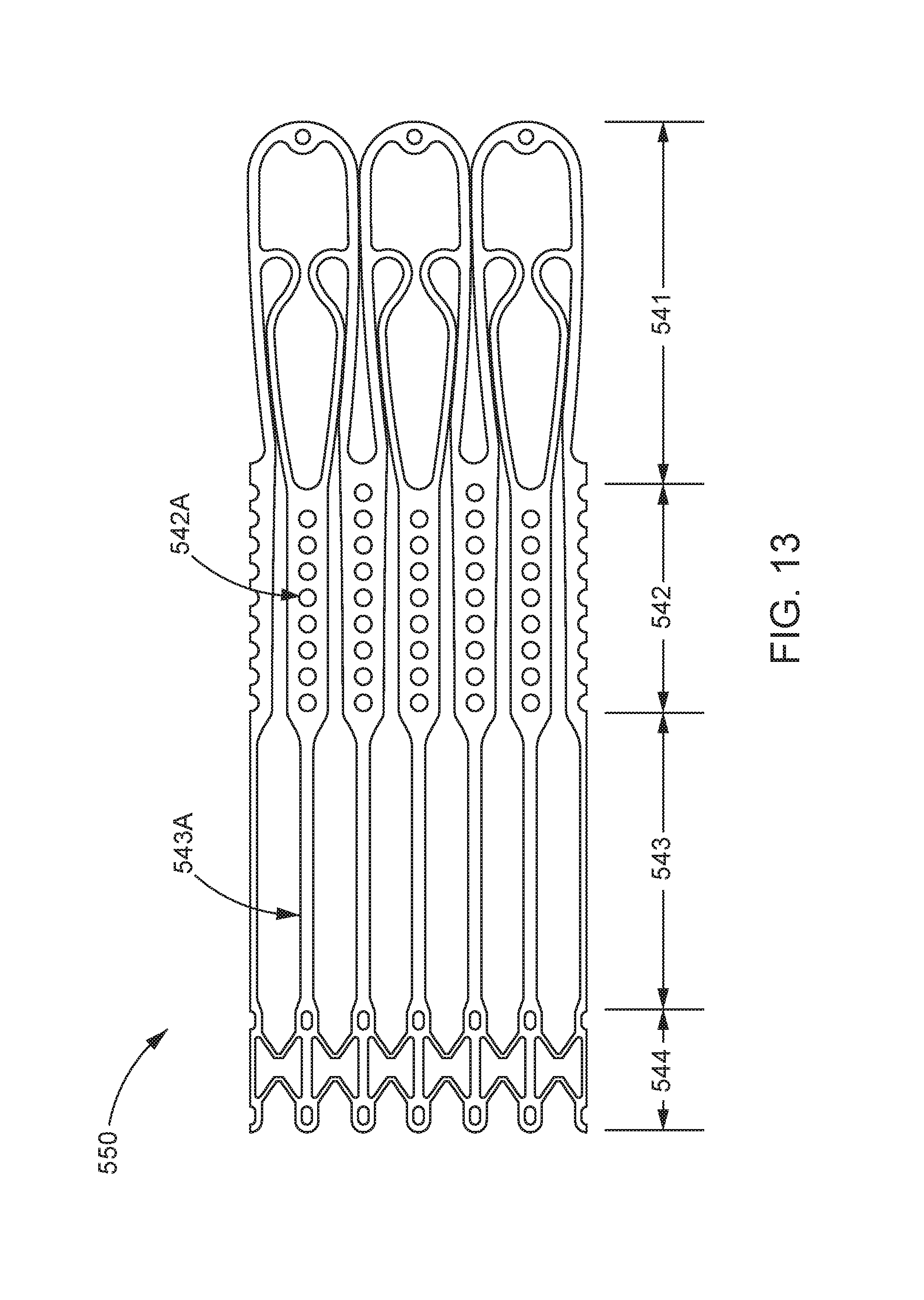
D00014

D00015

D00016

D00017

D00018

D00019

D00020

D00021

D00022

D00023

D00024

D00025

D00026

D00027

D00028

D00029

D00030

D00031

D00032

D00033

D00034

D00035

D00036

D00037

D00038

D00039

D00040
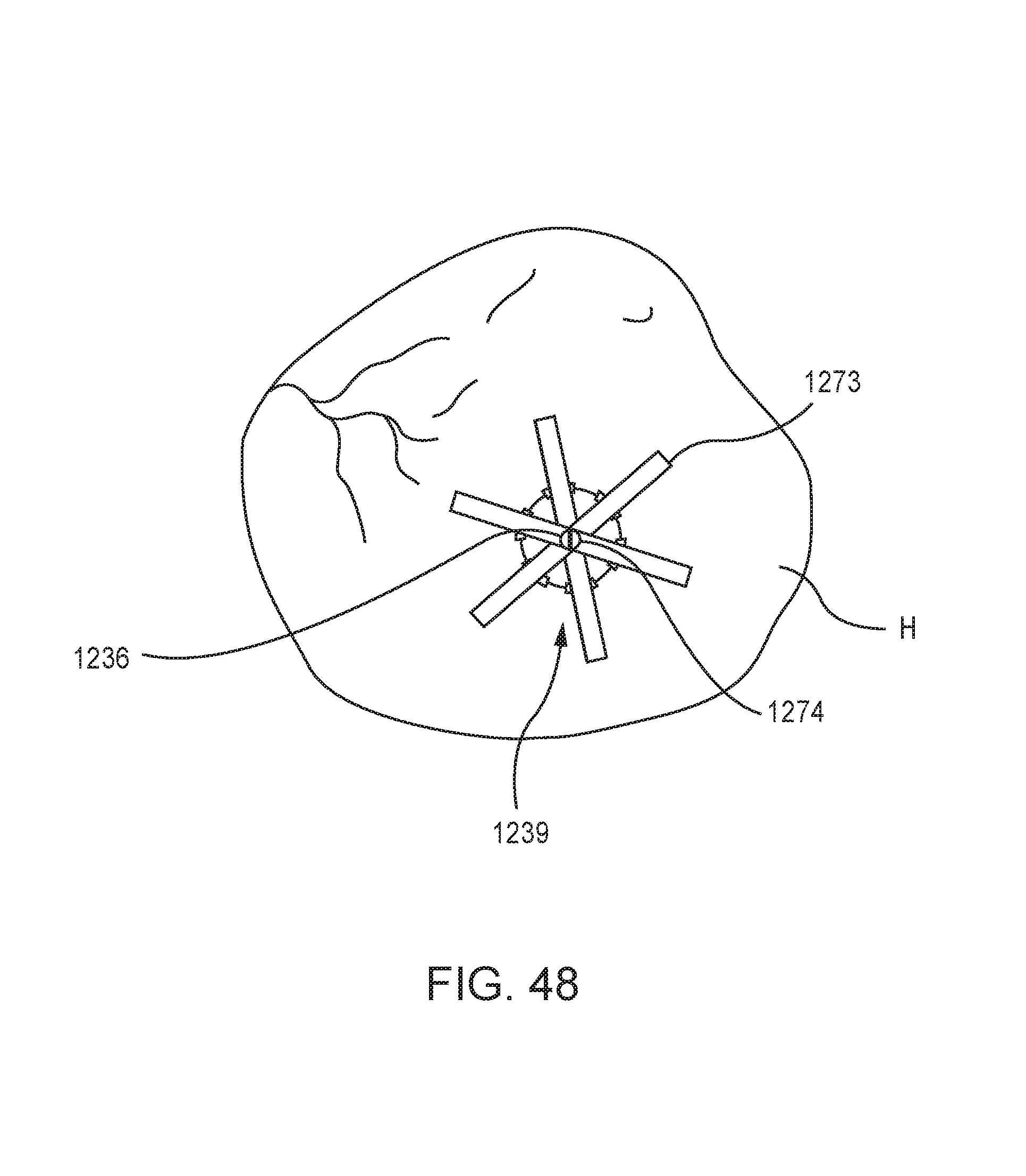
D00041

D00042

D00043

D00044

D00045

D00046

D00047

D00048

D00049

D00050

D00051

XML
uspto.report is an independent third-party trademark research tool that is not affiliated, endorsed, or sponsored by the United States Patent and Trademark Office (USPTO) or any other governmental organization. The information provided by uspto.report is based on publicly available data at the time of writing and is intended for informational purposes only.
While we strive to provide accurate and up-to-date information, we do not guarantee the accuracy, completeness, reliability, or suitability of the information displayed on this site. The use of this site is at your own risk. Any reliance you place on such information is therefore strictly at your own risk.
All official trademark data, including owner information, should be verified by visiting the official USPTO website at www.uspto.gov. This site is not intended to replace professional legal advice and should not be used as a substitute for consulting with a legal professional who is knowledgeable about trademark law.