Ankle replacement system and method
McGinley , et al.
U.S. patent number 10,321,922 [Application Number 15/335,949] was granted by the patent office on 2019-06-18 for ankle replacement system and method. This patent grant is currently assigned to Wright Medical Technology, Inc.. The grantee listed for this patent is Wright Medical Technology, Inc.. Invention is credited to Braham K. Dhillon, Robert M. Howles, Ramon Luna, Shawn E. McGinley.


View All Diagrams
| United States Patent | 10,321,922 |
| McGinley , et al. | June 18, 2019 |
Ankle replacement system and method
Abstract
A position adjustment device having a tool holder is locked to at least two pins projecting from respective anterior facing locations near a distal end of a tibia of a patient. The position adjustment device is adjusted. The position adjustment device is locked with the tool holder at first coordinates in the proximal-distal and medial-lateral directions. The distal end of the tibia is resectioned with a tool positioned on the tool holder, while the tool holder is in the first coordinates in the proximal-distal and medial-lateral directions. The tool is removed from the tool holder. A tibia trial is placed on the resectioned tibia using the tool holder, while the tool holder is in the first coordinates in the proximal-distal and medial-lateral directions. The tibia trial has a size and shape of a tibial tray of an ankle replacement system.
| Inventors: | McGinley; Shawn E. (Arlington, TN), Dhillon; Braham K. (Memphis, TN), Luna; Ramon (Arlington, TN), Howles; Robert M. (Bartlett, TN) | ||||||||||
|---|---|---|---|---|---|---|---|---|---|---|---|
| Applicant: |
|
||||||||||
| Assignee: | Wright Medical Technology, Inc.
(Memphis, TN) |
||||||||||
| Family ID: | 51018089 | ||||||||||
| Appl. No.: | 15/335,949 | ||||||||||
| Filed: | October 27, 2016 |
Prior Publication Data
| Document Identifier | Publication Date | |
|---|---|---|
| US 20170042555 A1 | Feb 16, 2017 | |
Related U.S. Patent Documents
| Application Number | Filing Date | Patent Number | Issue Date | ||
|---|---|---|---|---|---|
| 14100799 | Dec 9, 2013 | 9480571 | |||
| 61746393 | Dec 27, 2012 | ||||
| Current U.S. Class: | 1/1 |
| Current CPC Class: | A61B 17/1682 (20130101); A61B 17/17 (20130101); A61B 17/15 (20130101); A61F 2/4684 (20130101); A61F 2/4202 (20130101); A61F 2002/4205 (20130101); A61B 17/1775 (20161101) |
| Current International Class: | A61B 17/16 (20060101); A61B 17/17 (20060101); A61F 2/46 (20060101); A61B 17/15 (20060101); A61F 2/42 (20060101) |
References Cited [Referenced By]
U.S. Patent Documents
| 3839742 | October 1974 | Link |
| 3872519 | March 1975 | Giannestras et al. |
| 3886599 | June 1975 | Schlein |
| 3889300 | June 1975 | Smith |
| 3896502 | July 1975 | Lennox |
| 3896503 | July 1975 | Freeman et al. |
| 3975778 | August 1976 | Newton, III |
| 3987500 | October 1976 | Schlein |
| 4021864 | May 1977 | Waugh |
| 4069518 | January 1978 | Groth, Jr. et al. |
| 4156944 | June 1979 | Schreiber et al. |
| 4166292 | September 1979 | Bokros |
| 4204284 | May 1980 | Koeneman |
| 4232404 | November 1980 | Samuelson et al. |
| 4309778 | January 1982 | Buechel et al. |
| 4470158 | September 1984 | Pappas et al. |
| 4755185 | July 1988 | Tarr |
| 4968316 | November 1990 | Hergenroeder |
| 5041139 | August 1991 | Brangnemark |
| 5312412 | May 1994 | Whipple |
| 5326365 | July 1994 | Alvine |
| 5354300 | October 1994 | Goble et al. |
| 5423825 | June 1995 | Levine |
| 5476466 | December 1995 | Barrette et al. |
| 5601563 | February 1997 | Burke et al. |
| 5628749 | May 1997 | Vendrely et al. |
| 5634927 | June 1997 | Houston et al. |
| 5735904 | April 1998 | Pappas |
| 5766259 | June 1998 | Sammarco |
| 5776200 | July 1998 | Johnson et al. |
| 5817097 | October 1998 | Howard et al. |
| 5824106 | October 1998 | Fournol |
| 5879389 | March 1999 | Koshino |
| 5885299 | March 1999 | Winslow et al. |
| 5888203 | March 1999 | Goldberg |
| 5897559 | April 1999 | Masini |
| 5935132 | August 1999 | Bettuchi et al. |
| 6002859 | December 1999 | DiGioia, III et al. |
| 6033405 | March 2000 | Winslow et al. |
| 6102952 | August 2000 | Koshino |
| 6183519 | February 2001 | Bonnin et al. |
| 6245109 | June 2001 | Mendes et al. |
| 6342056 | January 2002 | Mac-Thiong et al. |
| 6409767 | June 2002 | Perice et al. |
| 6436146 | August 2002 | Hassler et al. |
| 6478800 | November 2002 | Fraser et al. |
| 6520964 | February 2003 | Tallarida et al. |
| 6530930 | March 2003 | Marino et al. |
| 6610067 | August 2003 | Tallarida et al. |
| 6610095 | August 2003 | Pope et al. |
| 6620168 | September 2003 | Lombardo et al. |
| 6645215 | November 2003 | McGovern et al. |
| 6663669 | December 2003 | Reiley |
| 6673116 | January 2004 | Reiley |
| 6679917 | January 2004 | Ek |
| 6719799 | April 2004 | Kropf |
| 6824567 | November 2004 | Tornier et al. |
| 6852130 | February 2005 | Keller et al. |
| 6860902 | March 2005 | Reiley |
| 6863691 | March 2005 | Short et al. |
| 6875222 | April 2005 | Long et al. |
| 6875236 | April 2005 | Reiley |
| 6926739 | August 2005 | O'Connor et al. |
| 6939380 | September 2005 | Guzman |
| 6942670 | September 2005 | Heldreth et al. |
| 7001394 | February 2006 | Gundlapalli et al. |
| 7011687 | March 2006 | Deffenbaugh et al. |
| 7025790 | April 2006 | Parks et al. |
| 7163541 | January 2007 | Ek |
| 7238190 | July 2007 | Schon et al. |
| 7252684 | August 2007 | Dearnaley |
| 7314488 | January 2008 | Reiley |
| 7323012 | January 2008 | Stone et al. |
| 7476227 | January 2009 | Tornier et al. |
| 7481814 | January 2009 | Metzger |
| 7485147 | February 2009 | Pappas et al. |
| 7534246 | May 2009 | Reiley et al. |
| 7534270 | May 2009 | Ball |
| 7615082 | November 2009 | Naegerl et al. |
| 7618421 | November 2009 | Axelson, Jr. et al. |
| 7625409 | December 2009 | Saltzman et al. |
| 7641697 | January 2010 | Reiley |
| 7678151 | March 2010 | Ek |
| 7713305 | May 2010 | Ek |
| 7717920 | May 2010 | Reiley |
| 7763080 | July 2010 | Southworth |
| 7803158 | September 2010 | Hayden |
| 7850698 | December 2010 | Straszheim-Morley et al. |
| 7896883 | March 2011 | Ek et al. |
| 7896885 | March 2011 | Miniaci et al. |
| 7909882 | March 2011 | Stinnette |
| 7963996 | June 2011 | Saltzman et al. |
| 8002841 | August 2011 | Hasselman |
| 8012217 | September 2011 | Strzepa et al. |
| 8034114 | October 2011 | Reiley |
| 8034115 | October 2011 | Reiley |
| 8048164 | November 2011 | Reiley |
| 8110006 | February 2012 | Reiley |
| 8114091 | February 2012 | Ratron et al. |
| 8167888 | May 2012 | Steffensmeier |
| 8172850 | May 2012 | McMinn |
| 8177841 | May 2012 | Ek |
| 8268007 | September 2012 | Barsoum et al. |
| 8303667 | November 2012 | Younger |
| 8313492 | November 2012 | Wong et al. |
| 8323346 | December 2012 | Tepic |
| 8337503 | December 2012 | Lian |
| 8361159 | January 2013 | Ek |
| 8475463 | July 2013 | Lian |
| 8491596 | July 2013 | Long et al. |
| 8808303 | August 2014 | Stemniski et al. |
| 9907561 | March 2018 | Luna et al. |
| 2002/0082607 | June 2002 | Heldreth et al. |
| 2002/0133164 | September 2002 | Williamson |
| 2002/0173853 | November 2002 | Corl, III et al. |
| 2003/0208280 | November 2003 | Tohidi |
| 2003/0236522 | December 2003 | Long et al. |
| 2004/0030399 | February 2004 | Asencio |
| 2004/0039394 | February 2004 | Conti et al. |
| 2004/0068322 | April 2004 | Ferree |
| 2004/0167631 | August 2004 | Luchesi et al. |
| 2004/0186585 | September 2004 | Feiwell |
| 2004/0216259 | November 2004 | Ponziani |
| 2004/0236431 | November 2004 | Sekel |
| 2005/0004676 | January 2005 | Schon et al. |
| 2005/0165408 | July 2005 | Puno et al. |
| 2005/0192674 | September 2005 | Ferree |
| 2006/0009857 | January 2006 | Gibbs et al. |
| 2006/0020345 | January 2006 | O'Connor et al. |
| 2006/0036257 | February 2006 | Steffensmeier |
| 2006/0116679 | June 2006 | Lutz et al. |
| 2006/0142870 | June 2006 | Robinson et al. |
| 2006/0235541 | October 2006 | Hodorek |
| 2006/0247788 | November 2006 | Ross |
| 2007/0038303 | February 2007 | Myerson et al. |
| 2007/0100346 | May 2007 | Wyss et al. |
| 2007/0112431 | May 2007 | Kofoed |
| 2007/0162025 | July 2007 | Tornier et al. |
| 2007/0173944 | July 2007 | Keller et al. |
| 2007/0173947 | July 2007 | Ratron et al. |
| 2007/0213830 | September 2007 | Ammann et al. |
| 2007/0233129 | October 2007 | Bertagnoli et al. |
| 2007/0276400 | November 2007 | Moore et al. |
| 2008/0015602 | January 2008 | Axelson |
| 2008/0097617 | April 2008 | Fellinger et al. |
| 2008/0103603 | May 2008 | Hintermann |
| 2008/0109081 | May 2008 | Bao et al. |
| 2008/0195233 | August 2008 | Ferrari et al. |
| 2008/0215156 | September 2008 | Duggal et al. |
| 2008/0287954 | November 2008 | Kunz et al. |
| 2008/0312745 | December 2008 | Keller et al. |
| 2009/0054992 | February 2009 | Landes et al. |
| 2009/0082875 | March 2009 | Long |
| 2009/0105767 | April 2009 | Reiley |
| 2009/0105840 | April 2009 | Reiley |
| 2009/0182433 | July 2009 | Reiley et al. |
| 2009/0198341 | August 2009 | Choi et al. |
| 2009/0234360 | September 2009 | Alexander |
| 2009/0276052 | November 2009 | Regala et al. |
| 2010/0010493 | January 2010 | Dower |
| 2010/0023066 | January 2010 | Long et al. |
| 2010/0023126 | January 2010 | Grotz |
| 2010/0057216 | March 2010 | Gannoe et al. |
| 2010/0069910 | March 2010 | Hasselman |
| 2010/0198355 | August 2010 | Kofoed et al. |
| 2010/0241237 | September 2010 | Pappas |
| 2010/0305572 | December 2010 | Saltzman et al. |
| 2010/0318088 | December 2010 | Warne et al. |
| 2010/0331984 | December 2010 | Barsoum et al. |
| 2011/0029090 | February 2011 | Zannis et al. |
| 2011/0035018 | February 2011 | Deffenbaugh et al. |
| 2011/0035019 | February 2011 | Goswami et al. |
| 2011/0106268 | May 2011 | Deffenbaugh et al. |
| 2011/0125200 | May 2011 | Hanson et al. |
| 2011/0125275 | May 2011 | Lipman et al. |
| 2011/0125284 | May 2011 | Gabbrielli et al. |
| 2011/0152868 | June 2011 | Kourtis et al. |
| 2011/0152869 | June 2011 | Ek et al. |
| 2011/0166608 | July 2011 | Duggal et al. |
| 2011/0190829 | August 2011 | Duggal et al. |
| 2011/0218542 | September 2011 | Lian |
| 2011/0253151 | October 2011 | Tochigi et al. |
| 2011/0276052 | November 2011 | Hasselman |
| 2011/0295380 | December 2011 | Long |
| 2012/0010718 | January 2012 | Still |
| 2012/0046753 | February 2012 | Cook et al. |
| 2012/0053644 | March 2012 | Landry et al. |
| 2012/0083789 | April 2012 | Blakemore et al. |
| 2012/0109131 | May 2012 | Vasarhelyi et al. |
| 2012/0109326 | May 2012 | Perler |
| 2012/0130376 | May 2012 | Loring et al. |
| 2012/0136443 | May 2012 | Wenzel |
| 2012/0185057 | July 2012 | Abidi et al. |
| 2012/0191210 | July 2012 | Ratron et al. |
| 2012/0239045 | September 2012 | Li |
| 2012/0245701 | September 2012 | Zak et al. |
| 2012/0271430 | October 2012 | Arnett et al. |
| 2012/0277745 | November 2012 | Lizee |
| 2013/0041473 | February 2013 | Rouyer et al. |
| 2013/0116797 | May 2013 | Coulange et al. |
| 2016/0135815 | May 2016 | Loring et al. |
| 2480846 | Dec 2011 | GB | |||
| H11-500035 | Jan 1999 | JP | |||
| 2007-518453 | Jul 2007 | JP | |||
| 2007-519477 | Jul 2007 | JP | |||
| 2007536011 | Dec 2007 | JP | |||
| 2011526189 | Oct 2011 | JP | |||
| 2014-131738 | Jul 2014 | JP | |||
| 01/66021 | Sep 2001 | WO | |||
| 2005/011523 | Feb 2005 | WO | |||
| WO 2006/023824 | Mar 2006 | WO | |||
| WO 2006/099270 | Sep 2006 | WO | |||
| WO 2007/084846 | Jul 2007 | WO | |||
| WO 2009/158522 | Dec 2009 | WO | |||
| WO 2011/151657 | Dec 2011 | WO | |||
| 2012088036 | Jun 2012 | WO | |||
Other References
|
Final Office Action issued in connection with corresponding Japanese Patent Application No. 2016-502443, dated May 15, 2018, 3 pages. cited by applicant . Extended European Search Report issued in connection with corresponding European Patent Application No. 18160378.8, dated Jun. 29, 2018, 7 pages. cited by applicant . Second Office Action issued in connection with corresponding Chinese Patent Application No. 2018071101785100, dated Jul. 16, 2018, 6 pages. cited by applicant . First Office Action issued for corresponding Japanese patent application No. 2016-117842, dated Sep. 12, 2017, 5 pages. cited by applicant . Search report issued for European patent application No. 13198280 dated Feb. 5, 2014. cited by applicant . International Search Report for International patent application No. PCT/US2014/027448 dated Jul. 7, 2014. cited by applicant . International Preliminary Report on Patentability issued by the International Bureau of WIPO in connection with International patent application No. PCT/US2014/027448, dated Sep. 15, 2015, 8 pages. cited by applicant . Partial European Search Report issued in connection with European patent application No. 14768333.8, dated Oct. 26, 2016, 6 pages. cited by applicant . Patent Examination Report No. 1 issued in connection with Australian patent application No. 2015202080, dated Jul. 5, 2016, 4 pages. cited by applicant . Extended European Search Report and Opinion issued in connection with European patent application No. 14768333.8, dated Jan. 30, 2017, 10 pages. cited by applicant . Examination Report No. 1 issued in connection with corresponding Australian Patent Application No. 20182000073, dated Dec. 24, 2018, 3 pages. cited by applicant . First Office Action issued in connection with corresponding Japanese Patent Application No. 2018-092289, dated Mar. 5, 2019, 2 pages. cited by applicant. |
Primary Examiner: Yang; Andrew
Attorney, Agent or Firm: Duane Morris LLP
Parent Case Text
This application is a division of U.S. patent application Ser. No. 14/100,799, filed Dec. 9, 2013, which is a non-provisional of U.S. Patent Application No. 61/746,393, which was filed Dec. 27, 2012, all of which are incorporated herein by reference in their entireties.
Claims
What is claimed is:
1. A method comprising: (a) locking a position adjustment device having a tool holder to at least two pins projecting from respective anterior facing locations near a distal end of a tibia of a patient; (b) adjusting the position adjustment device; (c) locking the position adjustment device with the tool holder at first coordinates in the proximal-distal and medial-lateral directions; (d) resectioning the distal end of the tibia with a tool positioned on the tool holder, while the tool holder is in the first coordinates in the proximal-distal and medial-lateral directions; (e) removing the tool from the tool holder; and (f) placing a tibia trial on the resectioned tibia using the tool holder, while the tool holder is in the first coordinates in the proximal-distal and medial-lateral directions, the tibia trial having a size and shape of a tibial tray of an ankle replacement system.
2. The method of claim 1, further comprising verifying size and shape of the resectioning using the tibia trial, prior to implanting the ankle replacement system.
3. The method of claim 1, further comprising, before step (f): (i) attaching the tibia trial to the tool holder; and (ii) adjusting the position adjustment device to position the tool holder in an anterior-posterior direction, while the tool holder is at the first coordinates in the proximal-distal and medial-lateral directions.
4. The method of claim 3, wherein step (ii) includes translating the tibia trial in the posterior direction until a predetermined portion of the tibia trail contacts an anterior cortex of the tibia.
5. The method of claim 4, wherein steps (i), (ii) and (f) are performed within inserting any additional location fixing pins into the tibia.
6. The method of claim 1, further comprising: (g) positioning a drill using the tibia trial; and (h) drilling at least one peg hole in a distal surface of the resectioned tibia, through at least one hole in the tibia trial.
7. The method of claim 1, further comprising installing an insert into the tibia trial while the tool holder is in the first coordinates in the proximal-distal and medial-lateral directions, the insert having a concave surface with a size and shape of a prosthetic tibia joint surface of the ankle replacement system.
8. The method of claim 7, further comprising positioning a floating trial to permit articulation with the concave surface of the insert trial while the tool holder is in the first coordinates in the proximal-distal and medial-lateral directions, the floating trial having a convex surface with a size and shape of a prosthetic talar dome of the ankle replacement system.
9. The method of claim 8, further comprising pinning the floating trial to a talus of the patent, while the floating trial is positioned to permit articulation with the concave surface of the insert trial.
10. The method of claim 9, wherein the pinning step includes inserting pins or K-wire through holes in the floating trial, the pins or K-wire suitable for positioning a guide for resectioning the talus.
11. The method of claim 1, wherein step (b) includes adjusting at least one adjustment screw to position a connection block in at least one of proximal-distal, medial-lateral and anterior-posterior directions, the connection block adapted to hold the tool or the tibia trial.
12. The method of claim 1, wherein step (d) includes: mounting a drill guide on the tool holder; drilling holes using the drill guide to define corners of a resectioning cut to be performed in the tibia.
13. The method of claim 12, wherein step (d) further includes: mounting a cut guide to the tool holder; and cutting the bone to connect the drilled holes.
14. The method of claim 1, wherein the tibia trial comprises: a plate having a top surface adapted to fit against a distal surface of the resectioned tibia, the plate having a plurality of holes to be used to locate peg holes in the resectioned tibia, the plate having a bottom surface adapted to receive an insert; an anterior tibia reference member extending from the plate, adapted to contact an anterior surface of the tibia when the tibia trial is properly positioned; and an anterior mounting portion sized and shaped to be mounted to the tool holder.
15. The method of claim 14, wherein the insert comprises: a top surface adapted to be detachably mounted to the bottom surface of the plate of the tibia trial; a concave bottom surface with a size and shape of a prosthetic tibia joint surface of the ankle replacement system.
16. The method of claim 15, a floating trial is inserted to contact the insert, the floating trial comprising: a member having at least one convex surface with a size and shape of a prosthetic talar dome of the ankle replacement system, to permit articulation with the concave surface of the insert, the member having a handle for manual positioning of the floating trial, the handle having a plurality of holes for inserting pins for locating a talar cut guide.
Description
FIELD
This disclosure relates to prosthetics generally, and more specifically to systems and methods for total ankle replacement.
BACKGROUND
The ankle is a joint that acts much like a hinge. The joint is formed by the union of three bones. The ankle bone is the talus. The top of the talus fits inside a socket that is formed by the lower end of the tibia, and the fibula, the small bone of the lower leg. Arthritis, bone degeneration and/or injury can cause ankle joint deterioration resulting in pain, reduced range of motion, and decreased quality of life. In many cases, physicians are recommending ankle replacement surgery with an implant as an option.
Available ankle replacement systems include, for example, the "INBONE" .TM. system sold by Wright Medical Technologies of Arlington, Tenn. The "INBONE" .TM. system includes a talar tray component with stem, which fit into a resectioned distal end of the tibia. A poly insert having a concave distal surface is joined to the tibial tray. A talar dome and stem are implanted in a resectioned proximal end of the talus. The poly insert is configured to articulate with the talar dome.
Associated tools enable the physician to immobilize the foot, while the physician performs appropriate drilling and resectioning of the bones, and implants the prosthetic ankle. An example of such a tool is described in U.S. Pat. No. 7,534,246.
Improved devices and methods are desired.
SUMMARY
In some embodiments, a position adjustment device having a tool holder is locked to at least two pins projecting from respective anterior facing locations near a distal end of a tibia of a patient. The position adjustment device is adjusted. The position adjustment device is locked with the tool holder at first coordinates in the proximal-distal and medial-lateral directions. The distal end of the tibia is resectioned with a tool positioned on the tool holder, while the tool holder is in the first coordinates in the proximal-distal and medial-lateral directions. The tool is removed from the tool holder. A tibia trial is placed on the resectioned tibia using the tool holder, while the tool holder is in the first coordinates in the proximal-distal and medial-lateral directions. The tibia trial has a size and shape of a tibial tray of an ankle replacement system.
BRIEF DESCRIPTION OF THE DRAWINGS
FIG. 1 is an isometric view of a position adjustment device, or adjustment block suitable for sizing and trialing an implant.
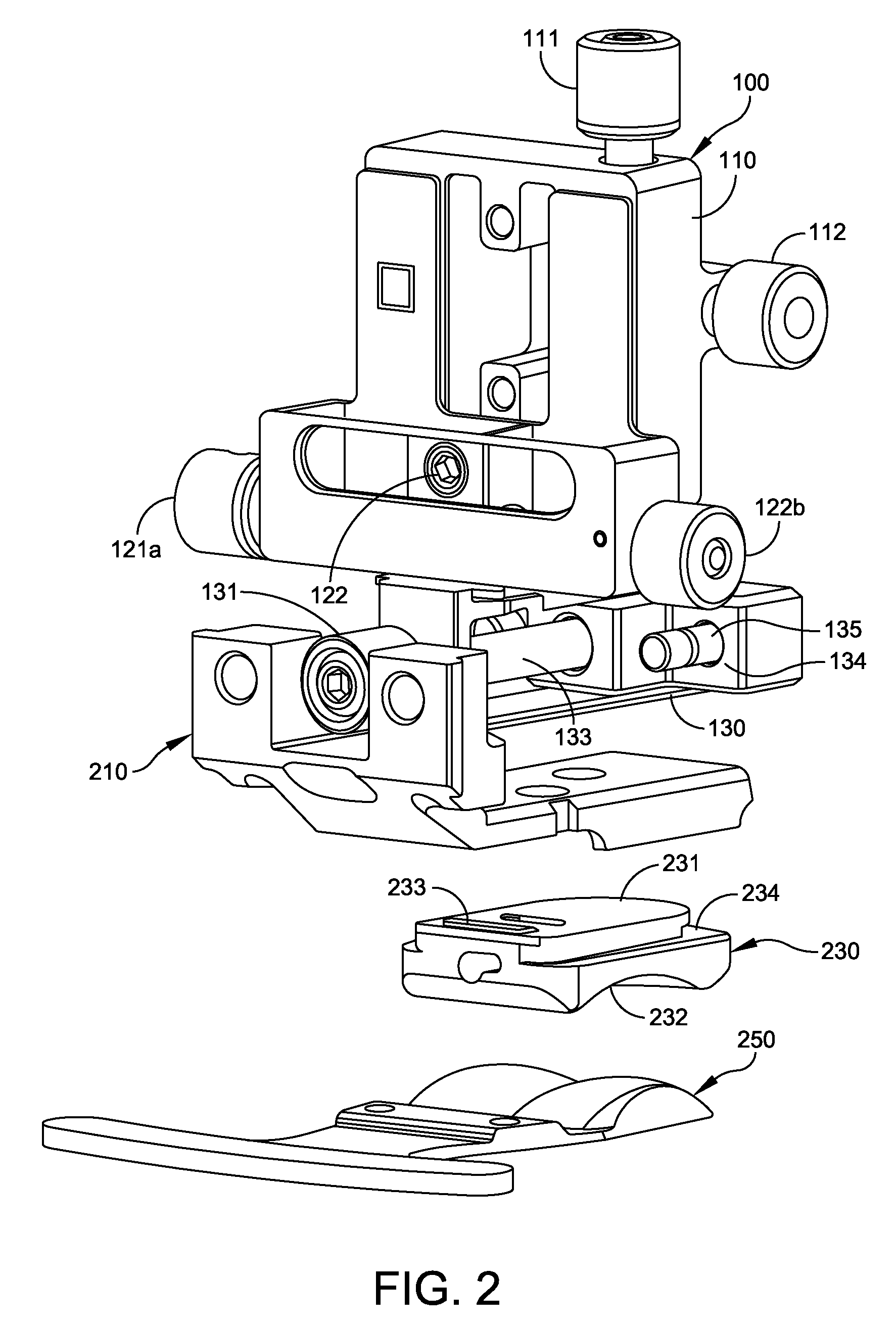
FIG. 2 is an exploded view showing the adjustment block, tibial trial, poly trial insert, and floating trial.
FIG. 3 is an isometric view of the tibia trial of FIG. 2.
FIG. 4 is an anterior elevation view of the tibia trial of FIG. 3.
FIG. 5 is a lateral elevation view of the tibia trial of FIG. 3.
FIG. 6 is an isometric view of the floating trial of FIG. 2.
FIG. 7 is an isometric view of an adjustment block of FIG. 1, holding a drilling guide.
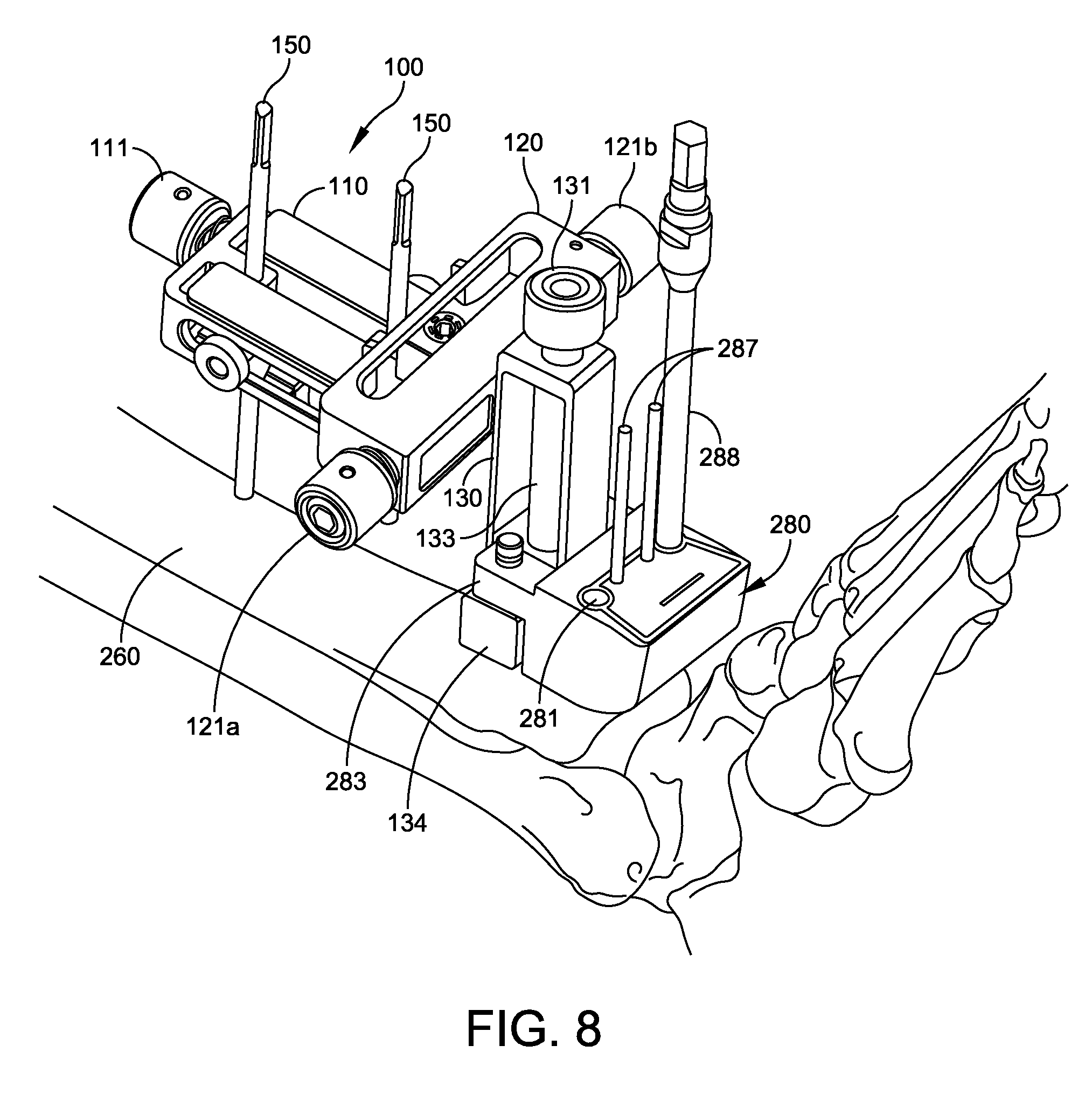
FIG. 8 is an isometric view of the adjustment block and drilling guide of FIG. 7, during the drilling operation.
FIG. 9 is an isometric view of the adjustment block of FIG. 1, holding a cut guide.
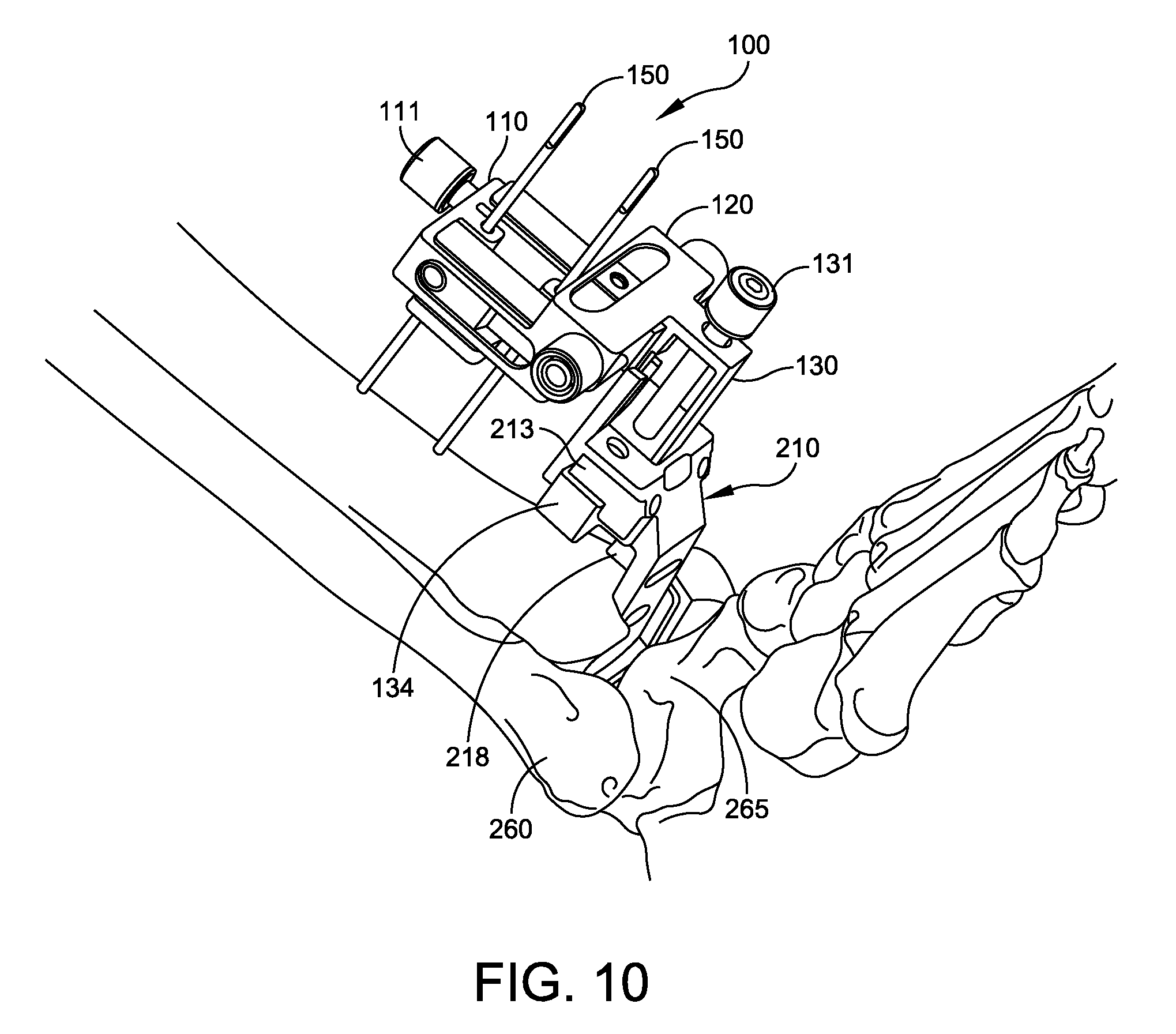
FIG. 10 is an isometric view showing the adjustment block and tibial trial during trial insertion.
FIG. 11 is a lateral side elevation view of the adjustment block and tibial trial during trial insertion.
FIG. 12 is an isometric view showing drilling using the tibia trial to locate peg holes in the distal surface of the tibia.
FIG. 13 shows the tibia and talus after resectioning.
FIG. 14 is an isometric view showing the adjustment block, tibial trial, poly trial insert, and floating trial inserted in the surgical window.
FIG. 15 is a lateral side elevation view of the adjustment block, tibial trial, poly trial insert, and floating trial inserted in the surgical window.
FIGS. 16 and 17 are isometric and lateral side elevation views showing the adjustment block, tibial trial, poly trial insert, and floating trial inserted while the floating trial is being pinned to the talus.
FIG. 18 is an isometric view of an embodiment of the adjustment block providing proximal-distal and medial-lateral adjustments.
FIG. 19 is an anterior top plan view of the adjustment block of FIG. 18, with a drill guide attached to its tool holder.
DETAILED DESCRIPTION
This description of the exemplary embodiments is intended to be read in connection with the accompanying drawings, which are to be considered part of the entire written description. In the description, relative terms such as "lower," "upper," "horizontal," "vertical,", "above," "below," "up," "down," "top" and "bottom" as well as derivative thereof (e.g., "horizontally," "downwardly," "upwardly," etc.) should be construed to refer to the orientation as then described or as shown in the drawing under discussion. These relative terms are for convenience of description and do not require that the apparatus be constructed or operated in a particular orientation. Terms concerning attachments, coupling and the like, such as "connected" and "interconnected," refer to a relationship wherein structures are secured or attached to one another either directly or indirectly through intervening structures, as well as both movable or rigid attachments or relationships, unless expressly described otherwise.
FIG. 1 is an isometric diagram of a position adjustment device 100 (also referred to below as an "adjustment block") for positioning of drilling and cutting tools for tibia resectioning, and for tibia trial insertion. The adjustment block 100 provides a common reference location for locating tools and the tibia trial components throughout the sizing, resectioning and trial procedure. In some embodiments, the adjustment block 100 is small enough in profile to position a cut guide into the wound space close to the tibia bone without applying excess skin tension. The physician can use the adjustment block to position a drill guide and/or cut guide closer to the tibia bone, to make more accurate cuts with less chance of the blade or pins flexing.
The adjustment block 100 has three independently positionable frames 110, 120, and 130 for precisely positioning a tool holder 134 adjacent the joint to be replaced.
The first frame 110 is configured to be attached to two fixation pins 150 which have been inserted in the anterior surface of the tibia, near the distal end of the tibia. A locking screw 112 actuates a locking plate (not shown), which bears against the fixation pins 150 to secure the adjustment block 100 relative to the pins. The first frame has a proximal-distal adjustment knob 111 coaxially connected to a screw 113. The screw 113 can have an Acme thread, trapezoidal thread, square thread or other suitable thread for leadscrew use. The second frame 120 is fixedly attached or unitarily formed with a leadscrew nut (not shown), which the screw 113 drives. Rotation of the proximal-distal adjustment knob 111 rotates screw 113 to advance or retract the second frame 120 in the proximal-distal direction. When the second frame 120 is at the desired proximal-distal coordinate, the physician advances the locking screw 114 to lock the second frame 120 to the first frame 110 in place.
The second frame 120 has at least one medial-lateral adjustment knob 121a, 121b coaxially connected to a screw 123. The screw 123 can have an Acme thread, trapezoidal thread, square thread or other suitable thread for leadscrew use. The screw 123 drives a leadscrew nut (not shown), to which the third frame 130 is fixedly attached or unitarily formed with. Rotation of the medial-lateral adjustment knob 121a or 121b rotates screw 123 to move the third frame 130 in the medial-lateral direction. When the third frame 130 is at the desired medial-lateral coordinate, the physician advances the locking screw 122 to lock the leadscrew 123 of the second frame 120 in place.
The third frame 130 has an anterior-posterior adjustment knob 131 coaxially connected to a screw 133. The screw 133 can have an Acme thread, trapezoidal thread, square thread or other suitable thread for leadscrew use. The screw 133 drives a leadscrew nut 136, to which a tool holder 134 is fixedly attached or with which tool holder 134 is unitarily formed. Rotation of the anterior-posterior adjustment knob 131 rotates screw 133 to move the tool holder 134 in the anterior-posterior direction. The tool holder 134 is adapted to hold a drilling tool, a cutting tool, or a tibia trial 210.
FIG. 2 is an exploded view showing the adjustment block 100, tibia trial 210, poly trial insert 230 and floating trial 250. FIG. 3 is an isometric view of the tibia trial 210. FIG. 4 is an anterior (rear) elevation view of the tibia trial 210. FIG. 5 is a sagittal (side) elevation view of the tibia trial 210.
The tibia trial 210 provides the profile of the tibia tray portion of an ankle replacement system. The tibia trial 210 comprises a plate 211 with a top surface adapted to fit against a distal surface 262 of the resectioned tibia 260. The plate 211 has a plurality of holes 212 to be used to locate peg holes 263 in the resectioned tibia 260. The plate 211 has a bottom surface 216 adapted to receive a trial insert, such as a poly trial insert 230. An anterior tibia reference member 218 extends from the plate 211. The anterior tibia reference member 218 has a posterior surface 219 adapted to contact an anterior surface 261 of the tibia 260 when the tibia trial 210 is properly positioned. The tibia trial 210 has an anterior mounting portion 213 sized and shaped to be mounted to the tool holder 134 of the adjustment block 100. In some embodiments, the tibia trial 210 has a notch 217 for aligning an anterior surface of the poly trial insert 230 with the tibia trial 210. Alignment (or misalignment is readily visible by checking whether the notch 217 is aligned with an edge of the poly trial insert 230. In some embodiments, the tibia trial 210 is formed of a strong, corrosion resistant material such as stainless steel or a titanium alloy.
The poly trial insert 230 is configured to provide the profile of the poly insert of an ankle replacement system. The poly trial insert 230 comprises a top surface 231 adapted to be detachably mounted to the bottom surface of the plate 216 of the tibia trial 210. The poly insert 230 has a concave bottom surface 232 with a size and shape of a prosthetic tibia joint surface of the ankle replacement system. The thickness of the poly trial insert 230 matches the poly insert of the ankle replacement system to which the poly trial insert 230 corresponds, allowing verification of the size and thickness of the poly insert using the poly trial insert 230. In some embodiments, the poly insert of the ankle replacement system has a locking tab to prevent release from the talar tray after surgery; but the poly trial insert 230 has a non-locking tab 233 with a ramped surface, to be detachably inserted in the tibia trial 210 and removed after sizing and resectioning is completed. The non-locking tab 233 fits in a corresponding recess (not shown) in the bottom surface 216 of the tibia trial 210. The posterior end of the poly trial insert 230 has an undercut 234, In some embodiments, the poly trial insert 230 is made from the same type of material used in the poly insert of an ankle replacement system. In some embodiments, the poly trial insert 230 is made of a chemical-resistant material such as polyphenylsulfone, which is also referred to as RadelR.
FIG. 6 is an isometric view of the floating trial 250. The floating trial 250 is configured to provide a contour that matches the contour of the talar dome of the ankle replacement system. The floating trial 250 is configured to be inserted beneath the poly trial insert 230 to contact the concave bottom surface 232 of insert 230. The floating trial 250 comprises a member 251 having at least one convex anterior surface with a size and shape of a prosthetic talar dome of the ankle replacement system, to permit articulation with the concave surface 232 of the insert. The posterior surface 255 of the member 251 is shaped to match the contour of the resectioned talus. In some embodiments, the floating trial 250 has two convex surfaces 251. The floating trial 250 further includes a handle portion 252 which is sized to project from the resection site, so the physician can easily optimize the position of the floating trial for smooth articulation with the poly trial insert 230. The handle 252 of the floating trial 250 has a plurality of pin holes 253 for receiving fixation pins to be used for locating a talar cut guide (not shown). Once the position is optimized, the pins are inserted through the pin holes 253 before completing the resectioning of the talus. In some embodiments, the floating trial 250 is formed of a strong, corrosion resistant material such as stainless steel or a titanium alloy. In some embodiments, the floating trial 250 also has one or more anterior chamfers 254 for reference and alignment.
FIGS. 7-17 show various stages of a method of resectioning and trialing, using the adjustment block 100, optional drill guide 280, optional cut guide 290, tibia trial 210, poly trial insert 230 and floating trial 250. This is one example of a use of the devices, but is not limiting.
FIG. 7 shows the adjustment block 100 fixed to the fixation pins 150 (e.g., 3.2 mm pins) which have been inserted in the anterior surface of the tibia 260 near the distal end 261 of the tibia. FIG. 7 also shows a drill guide 280 attached to the tool holder 134 of the adjustment block 100, with the first frame 110 slightly above the anterior surface of the tibia 260. In some embodiments, the tool holder 134 is stage with a pair of pins 135, and the drill guide 280 has a corresponding pair of mounting ears 283 with holes adapted to snap onto the pins 135. This tool holder design is just exemplary in nature, and other embodiments include other suitable mounting structures.
In the embodiment of FIG. 7, the drill guide 280 is a small profile device sized and shaped to be inserted beneath the retracted skin (not shown) in the ankle region. The drill guide 280 has at least two guide holes 281 to be used to drill pilot holes in the tibia 260. The drill guide also has pin holes 282 that can be used to pin the drill guide to the bone, for position fixation. In some embodiments, the drill guide 280 has sizing patterns 285 showing the size and location of one or more resectioning cuts corresponding to the holes to be drilled using the drill guide 280. In some embodiments, the drill guide 280 has one or more reference lines 286 that the physician can optionally use to position the drill guide 280 (by adjusting the proximal-distal knob 111, the medial-lateral knob 121a or 121b, and the anterior-posterior knob. In some embodiments, the lines 285, 286 are visible under a fluoroscope, so the physician can view the position and size of the lines 285, 286 in situ, relative to the patient's bones.
The physician sizes the tibial tray component of the ankle replacement system by mounting a drill guide 280 on the tool holder and adjusting its position as described above. The position adjustment device (adjustment block) 100 is locked with the tool holder 134 at first coordinates in the proximal-distal and medial-lateral directions.
The physician views the X-ray of the tibia bone 260 and drill guide 280 and determines whether it is the optimum size and position for the patient. The position can be adjusted based on the X-ray, using knobs 111, 121, 131. If the size of the resectioning cut corresponding to the drill guide 280 is too large or too small, the physician removes the drill guide, selects a different size drill guide, and snaps the new drill guide onto the tool holder 134 of the adjustment block 100. The drill guide is then repositioned against the tibia, imaged by fluoroscope, and the size is again checked. To facilitate fluoroscopic X-ray imaging, the drill guide 280 can be made of plastic, while the circles surrounding holes 281 and the patterns 285, 286 can be made of metal. Thus, only the circles surrounding holes 281 and the patterns 285, 286 appear on the X-ray, superimposed against the tibia 260 and talus 265.
Although some embodiments use a single drill guide 280 for sizing, location of fixation pins by holes 282 and drilling corners 281, other embodiments (not shown) use a first guide (sizing guide) with holes 282 and patterns 285, 286 for sizing the tibia trial 210 and locating the fixation pins, and a second guide (drilling guide) with holes 281 and 282 for performing the drilling. Because the adjustment block 100 and the pins in holes 282 provide common references, the holes 281 can still be drilled with proper location relative to the pin holes 282 and patterns 285, 286.
FIG. 8 shows the tibia 260 with adjustment block 100 and drill guide 280. Soft tissue is omitted for ease of viewing. When the physician has verified that the optimum size of drill guide 280 has been selected, the physician pins the drill guide 280 to the tibia 260 using (e.g., 2.4 mm) fixation pins 287 inserted through the pin holes 282 and trimmed to extend slightly above the drill guide 280. Then the physician drills holes in the tibia 260 through the guides holes 281 using the drill guide 280 and drill 288. The holes thus drilled in the bone 260 define corners of a resectioning cut to be performed in the tibia. The physician then removes the drill guide 280, while leaving the pins 287 in place (in the distal portion of the tibia 260 to be removed by the resectioning). While removing the drill guide 280, the adjustment block can remain locked in the first coordinates with the first frame 110 adjusted to the same proximal-distal coordinate and the second frame 120 adjusted to the same medial-lateral coordinate.
FIG. 9 shows the adjustment block 100 still fixed to the fixation pins 150 in the same position, with a cut guide 290 mounted to the tool holder 134 of the adjustment block 100. The cut guide 290 has a plurality of slots 295, sized and located to connect the corner holes drilled with the drill guide 280. The cut guide 290 is sized and shaped to match the drill guide 280. Thus, the physician has a set of drill guides 280 and a corresponding set of cut guides 290. The selection of a drill guide size automatically selects the corresponding cut guide size to make cuts which are sized and located to connect the corner holes drilled with the drill guide 280, as described above. The cut guide 290 has a corresponding pair of mounting ears 293 with holes adapted to snap onto the pins 135. The cut guide 290 also has pin holes 292 which are sized and located to receive the fixation pins 287. This aligns the position of the cut guide 290 with the position previously occupied by the drill guide 280, to ensure alignment of the resectioning cuts with the previously drilled corner holes. In some embodiments, the cut guide 290 includes additional ears 296 with pin holes for receiving additional fixation pins 297.
To mount the cut guide 290, the physician slides the holes 292 of cut guide 290 over the fixation pins 287 and snaps the cut guide into place on the tool holder 134. For stability, the physician can then insert two more fixation pins 297 through the pin holes of ears 296 and into the talus bone 265. With the cut guide 290 and bones 260, 265 securely pinned, the physician performs the resectioning cuts through the guide slots 295, cutting the bone to connect the previously drilled holes. In some embodiments, as shown in FIG. 9, one cut guide 290 is used for both the tibia resection and the first cut of the talar resection. The cut guide 290 is then removed from the surgery site, and detached from the adjustment block 100. The sections of the tibia 260 and talus 265 that have been cut are removed, along with the fixation pins 287 and 297. In other embodiments (not shown), the tibia cut guide is only used to resection the tibia, and a separate cut guide is used to resection the talus after removal of the tibia cut guide.
The use of the adjustment block 100 permits the holes 281 to be drilled first with a first tool, and the cuts to be performed afterwards with a second tool, while maintaining accurate alignment between the holes and the cuts. Drilling the holes first avoids stress concentrations at the corners of the resectioned distal tibia.
Although some embodiments described herein use a drill guide 280 and a cut guide 290 commonly fixed using the adjustment block 100 and fixation pins 287, other embodiments attach different tools to the tool holder 134 for purpose of resectioning the tibia and talus. For example, some embodiments (not shown) include a cut guide without using a separate drill guide.
Following the initial resectioning, the physician inserts the tibia trial 210, poly trial insert 230 and floating trial 250, while the adjustment block 100 is still locked to the two fixation pins 150, and the tool holder 134 is in the first coordinates in the proximal-distal and medial-lateral directions. Should the physician choose to temporarily remove the adjustment block from the surgery site (e.g., for inspection, cleaning or suctioning), the physician returns the adjustment block to the same coordinates to locate the tool holder 134 at the same position to complete the procedure. Because the fixation pins 150 are excluded from the distal portion of the tibia removed by the resection, the fixation pins 150 are available throughout the procedure for use in adjusting or correcting the resection cuts.
The physician snaps the tibia trial 210 onto the tool holder 134. FIGS. 10 and 11 show the adjustment block in position with the tibia trial 210 attached. The adjustment block 100 is adjusted to position the tool holder in an anterior-posterior direction, while the tool holder is at the first coordinates in the proximal-distal and medial-lateral directions. The tibia trial 210 is repositioned in the posterior direction until a predetermined portion of the tibia trail contacts an anterior cortex of the tibia. In some embodiments, the position of the third frame 130 is adjusted until the posterior surface 219 of anterior tibia reference member 218 extending from the plate 211 contacts the anterior cortex of the tibia 260.
FIG. 12 shows the tibia 260 and talus 265 with the adjustment block and tibia trial 210 in position. The tibia peg drill (not shown) is placed in the head of a tibia peg drill guide 299, and is inserted in the holes 212 (FIG. 3) of the tibia trial 210. The physician drills a plurality (e.g., 3) peg holes 263 in the distal surface 262 of the resectioned tibia 260 using the tibia peg drill 299. The holes 212 (FIG. 3) of the tibia trial 210 are used to locate these holes 263. FIG. 13 shows the distal end 261 of the tibia 260 at the completion of the peg drilling, with the three peg holes 263 in the resectioned surface 262 of the tibia.
The tibia trial 210 is used to verify size and shape of the resectioning using the tibia trial, prior to implanting the ankle replacement system. Advantageously, the steps of attaching the tibia trial 210 to the tool holder 134, adjusting the position adjustment device 100 to position the tool holder 134 in an anterior-posterior direction, and placing the tibia trial 210 on the resectioned tibia 260 using the tool holder 134, can be formed without inserting any additional location fixing pins into the tibia, while the tool holder is locked in the first coordinates in the proximal-distal and medial-lateral directions.
FIGS. 14 and 15 show the adjustment block 100 and tibia trial 210, after installing the poly trial insert 230 into the tibia trial 210 and positioning the floating trial 250 between the talus 265 and the poly insert trial 230, to permit articulation with the concave surface 232 of the poly insert trial 230 while the tool holder is in the first coordinates in the proximal-distal and medial-lateral directions. The physician can now assess the fit of the ankle replacement system, including size, anterior-posterior position, and whether the tibia has been sized, drilled and cut optimally. If any adjustments are deemed appropriate to the tibia resectioning, the physician can reapply the cut guide with the adjustment block set to the same proximal-distal and medial-lateral coordinates used before.
Referring to FIGS. 16 and 17, the physician now performs a trial reduction to ensure the correct poly insert height and talus dome position. The talar implant anterior-posterior coordinate is determined by moving the floating trial 250 to the location where it best articulates with the concave surface 232 of the poly trial insert 230. Two additional fixation pins 298 are inserted through the pin holes 253 of the floating trial 250 using 2 mm K-wire, for example. Additional resection guides (not shown) can be positioned by sliding pin holes in the resection guide(s) over the fixation pins 298. The remaining two talar cuts are then performed, to match the geometry of the talar dome implant of the ankle replacement system.
A position adjustment device (adjustment block) 100 as described above provides a fixed point of reference that facilitates the AP position of the tibial and talar implants of an ankle replacement system. The adjustment block 100 is capable of fixing a tibial trial 210 via a modular connection 134 to avoid insertion of additional pins in the distal tibia. The tibial trial 210, while attached to the adjustment block 100, allows the user to set the tibial implant anterior-posterior position by abutting the anterior post 218 against the tibial bone. The tibial trial 210 also serves as a drill guide to prepare the tibial pegs on the tibial implant.
The tibial trial 210 while rigidly fixed to the adjustment block 100 then translates the anterior-posterior position to the talar trial 250 by using the poly trial insert 230 to articulate with the talar (dome) trial 250. The talar trial 250 also has chamfer indicators 254 to help the user determine the optimal talar anterior-posterior position.
Advantageously, the system and method described above uses the adjustment block 100 as a fixed reference to associate all other instruments used for trial sizing and trials related to tibial side of the ankle replacement. Thus, a tibial sizer (e.g., drill guide 280), tibial resection guide (e.g., cut guide 290), and tibial trial 210 can all be anchored at the same position defined by the adjustment block 100. This method preserves the distal layer of the tibia to avoid excess pin holes from fixation pins and devices.
The compact size of the adjustment block allows the tools to be fixed and placed close to the surgery site, for more accurate cuts, with reduced chance of components flexing. Sizing guides (e.g., drill guide 280) and resection guides (e.g. cut guide 290) can all be placed in the surgical window. The position of the tools and trials can be accurately adjusted by turning the adjustment knobs 111, 121, 131 in a small area.
FIGS. 18 and 19 show another embodiment of the adjustment block 300. The adjustment block 300 has two independently positionable frames 110, 120 for precisely positioning a tool holder 330 in the proximal-distal and medial-lateral directions, adjacent the joint to be replaced.
The first frame 110 is configured to be attached to two fixation pins 150 which have been inserted in the anterior surface of the tibia, near the distal end of the tibia. A locking screw 112 actuates a locking plate (not shown), which bears against the fixation pins 150 to secure the adjustment block 100 relative to the pins. The first frame has a proximal-distal adjustment knob 111 coaxially connected to a screw 113. The screw 113 can have an Acme thread, trapezoidal thread, square thread or other suitable thread for leadscrew use. The second frame 120 is fixedly attached or unitarily formed with a leadscrew nut (not shown), which the screw 113 drives. Rotation of the proximal-distal adjustment knob 111 rotates screw 113 to advance or retract the second frame 120 in the proximal-distal direction. When the second frame 120 is at the desired proximal-distal coordinate, the physician advances the locking screw 114 to lock the second frame 120 to the first frame 110 in place.
The second frame 120 has at least one medial-lateral adjustment knob 121a, 121b coaxially connected to a screw 123. The screw 123 can have an Acme thread, trapezoidal thread, square thread or other suitable thread for leadscrew use. The screw 123 drives a leadscrew nut (not shown), to which the tool holder 330 is fixedly attached or unitarily formed with. Rotation of the medial-lateral adjustment knob 121a or 121b rotates screw 123 to move the tool holder 330 in the medial-lateral direction. When the tool holder 330 is at the desired medial-lateral coordinate, the physician advances the locking screw 122 to lock the leadscrew 123 of the second frame 120 in place.
The position of the tool holder 330 in the anterior-posterior direction is determined by location of the first frame 110 relative to the pins 150.
The tool holder 330 can have any of a variety of configurations for easily attaching a tool or trial. FIGS. 18 and 19 show a non-limiting example in which the tool or trial is attached to the adjustment block 300 by a dovetail joint 332. FIG. 19 shows an example of a drill guide 380 adapted for mounting to the dovetail joint 332 of tool holder 330. The drill guide 380 has corner holes 381 and fixation holes 382, 383 and sizing patterns 385. Other tools (e.g., a cut guide) and trials (e.g., tibia trial) can be adapted to fit the tool holder 330.
Although the subject matter has been described in terms of exemplary embodiments, it is not limited thereto. Rather, the appended claims should be construed broadly, to include other variants and embodiments, which may be made by those skilled in the art.
* * * * *
D00000
D00001
D00002
D00003
D00004
D00005
D00006
D00007
D00008
D00009
D00010
D00011
D00012

D00013

D00014

D00015

D00016

D00017

XML
uspto.report is an independent third-party trademark research tool that is not affiliated, endorsed, or sponsored by the United States Patent and Trademark Office (USPTO) or any other governmental organization. The information provided by uspto.report is based on publicly available data at the time of writing and is intended for informational purposes only.
While we strive to provide accurate and up-to-date information, we do not guarantee the accuracy, completeness, reliability, or suitability of the information displayed on this site. The use of this site is at your own risk. Any reliance you place on such information is therefore strictly at your own risk.
All official trademark data, including owner information, should be verified by visiting the official USPTO website at www.uspto.gov. This site is not intended to replace professional legal advice and should not be used as a substitute for consulting with a legal professional who is knowledgeable about trademark law.