Antenna for use in a wearable device
Hirsch , et al.
U.S. patent number 10,297,911 [Application Number 15/949,740] was granted by the patent office on 2019-05-21 for antenna for use in a wearable device. This patent grant is currently assigned to BRAGI GmbH. The grantee listed for this patent is BRAGI GmbH. Invention is credited to Eric Christian Hirsch, Nikolaj Hviid.


View All Diagrams
| United States Patent | 10,297,911 |
| Hirsch , et al. | May 21, 2019 |
Antenna for use in a wearable device
Abstract
An earpiece includes a housing, a first short-range transceiver for far field communication disposed within the housing, and a second short range transceiver for near field communication disposed within the housing. The second short range transceiver for near field communications comprises an antenna formed from a plurality of coil turns. There is a battery disposed within the housing. The earpiece further includes a first generally planar printed circuit board disposed within the housing and a second generally planar printed circuit board disposed within the housing. There is a flexible connector between circuit boards. The battery is positioned between the first generally planar printed circuit board and the second generally planar printed circuit board. The antenna is mounted perpendicularly to the plurality of components mounted on the first generally planar printed circuit board to thereby reduce electromagnetic interference.
| Inventors: | Hirsch; Eric Christian (Munchen, DE), Hviid; Nikolaj (Munchen, DE) | ||||||||||
|---|---|---|---|---|---|---|---|---|---|---|---|
| Applicant: |
|
||||||||||
| Assignee: | BRAGI GmbH (Munchen,
DE) |
||||||||||
| Family ID: | 58104421 | ||||||||||
| Appl. No.: | 15/949,740 | ||||||||||
| Filed: | April 10, 2018 |
Prior Publication Data
| Document Identifier | Publication Date | |
|---|---|---|
| US 20180241117 A1 | Aug 23, 2018 | |
Related U.S. Patent Documents
| Application Number | Filing Date | Patent Number | Issue Date | ||
|---|---|---|---|---|---|
| 15349975 | Nov 11, 2016 | 9972895 | |||
| 14941639 | Jan 9, 2018 | 9866282 | |||
| PCT/EP2016/070216 | Aug 26, 2016 | ||||
| 62211725 | Aug 29, 2015 | ||||
| 62254591 | Nov 12, 2015 | ||||
| Current U.S. Class: | 1/1 |
| Current CPC Class: | H01Q 1/2291 (20130101); H04W 4/80 (20180201); H04B 5/0031 (20130101); H01Q 1/38 (20130101); H04B 1/385 (20130101); H04B 5/0081 (20130101); H01Q 1/273 (20130101); H01Q 7/08 (20130101); H04R 1/1016 (20130101) |
| Current International Class: | H04W 4/00 (20180101); H04W 4/80 (20180101); H04B 5/00 (20060101); H01Q 1/12 (20060101); H01Q 1/27 (20060101); H01Q 7/08 (20060101); H01Q 1/22 (20060101); H04B 1/3827 (20150101); H04B 5/02 (20060101); H01Q 1/38 (20060101) |
References Cited [Referenced By]
U.S. Patent Documents
| 2325590 | August 1943 | Carlisle et al. |
| 2430229 | November 1947 | Kelsey |
| 3047089 | July 1962 | Swislocki |
| D208784 | October 1967 | Sanzone |
| 3586794 | June 1971 | Michaelis |
| 3696377 | October 1972 | Wall |
| 3934100 | January 1976 | Harada |
| 3983336 | September 1976 | Malek et al. |
| 4069400 | January 1978 | Johanson et al. |
| 4150262 | April 1979 | Ono |
| 4334315 | June 1982 | Ono et al. |
| D266271 | September 1982 | Johanson et al. |
| 4375016 | February 1983 | Harada |
| 4588867 | May 1986 | Konomi |
| 4617429 | October 1986 | Bellafiore |
| 4654883 | March 1987 | Iwata |
| 4682180 | July 1987 | Gans |
| 4791673 | December 1988 | Schreiber |
| 4852177 | July 1989 | Ambrose |
| 4865044 | September 1989 | Wallace et al. |
| 4984277 | January 1991 | Bisgaard et al. |
| 5008943 | April 1991 | Arndt et al. |
| 5185802 | February 1993 | Stanton |
| 5191602 | March 1993 | Regen et al. |
| 5201007 | April 1993 | Ward et al. |
| 5201008 | April 1993 | Amdt et al. |
| D340286 | October 1993 | Seo |
| 5280524 | January 1994 | Norris |
| 5295193 | March 1994 | Ono |
| 5298692 | March 1994 | Ikeda et al. |
| 5343532 | August 1994 | Shugart |
| 5347584 | September 1994 | Narisawa |
| 5363444 | November 1994 | Norris |
| 5444786 | August 1995 | Raviv |
| D367113 | February 1996 | Weeks |
| 5497339 | March 1996 | Bernard |
| 5606621 | February 1997 | Reiter et al. |
| 5613222 | March 1997 | Guenther |
| 5654530 | August 1997 | Sauer et al. |
| 5692059 | November 1997 | Kruger |
| 5721783 | February 1998 | Anderson |
| 5748743 | May 1998 | Weeks |
| 5749072 | May 1998 | Mazurkiewicz et al. |
| 5771438 | June 1998 | Palermo |
| D397796 | September 1998 | Yabe et al. |
| 5802167 | September 1998 | Hong |
| 5844996 | December 1998 | Enzmann et al. |
| D410008 | May 1999 | Almqvist |
| 5929774 | July 1999 | Charlton |
| 5933506 | August 1999 | Aoki et al. |
| 5949896 | September 1999 | Nageno et al. |
| 5987146 | November 1999 | Pluvinage et al. |
| 6021207 | February 2000 | Puthuff et al. |
| 6054989 | April 2000 | Robertson et al. |
| 6081724 | June 2000 | Wilson |
| 6084526 | July 2000 | Blotky et al. |
| 6094492 | July 2000 | Boesen |
| 6111569 | August 2000 | Brusky et al. |
| 6112103 | August 2000 | Puthuff |
| 6157727 | December 2000 | Rueda |
| 6167039 | December 2000 | Karlsson et al. |
| 6181801 | January 2001 | Puthuff et al. |
| 6185152 | February 2001 | Shen |
| 6208372 | March 2001 | Barraclough |
| 6230029 | May 2001 | Yegiazaryan et al. |
| 6275789 | August 2001 | Moser et al. |
| 6339754 | January 2002 | Flanagan et al. |
| D455835 | April 2002 | Anderson et al. |
| 6408081 | June 2002 | Boesen |
| 6424820 | July 2002 | Burdick et al. |
| D464039 | October 2002 | Boesen |
| 6470893 | October 2002 | Boesen |
| D468299 | January 2003 | Boesen |
| D468300 | January 2003 | Boesen |
| 6542721 | April 2003 | Boesen |
| 6560468 | May 2003 | Boesen |
| 6563301 | May 2003 | Gventer |
| 6654721 | November 2003 | Handelman |
| 6664713 | December 2003 | Boesen |
| 6690807 | February 2004 | Meyer |
| 6694180 | February 2004 | Boesen |
| 6718043 | April 2004 | Boesen |
| 6738485 | May 2004 | Boesen |
| 6748095 | June 2004 | Goss |
| 6754358 | June 2004 | Boesen et al. |
| 6784873 | August 2004 | Boesen et al. |
| 6823195 | November 2004 | Boesen |
| 6852084 | February 2005 | Boesen |
| 6879698 | April 2005 | Boesen |
| 6892082 | May 2005 | Boesen |
| 6920229 | July 2005 | Boesen |
| 6952483 | October 2005 | Boesen et al. |
| 6987986 | January 2006 | Boesen |
| 7010137 | March 2006 | Leedom et al. |
| 7113611 | September 2006 | Leedom et al. |
| D532520 | November 2006 | Kampmeier et al. |
| 7136282 | November 2006 | Rebeske |
| 7203331 | April 2007 | Boesen |
| 7209569 | April 2007 | Boesen |
| 7215790 | May 2007 | Boesen et al. |
| D549222 | August 2007 | Huang |
| D554756 | November 2007 | Sjursen et al. |
| 7403629 | July 2008 | Aceti et al. |
| D579006 | October 2008 | Kim et al. |
| 7463902 | December 2008 | Boesen |
| 7508411 | March 2009 | Boesen |
| 7532901 | May 2009 | LaFranchise et al. |
| D601134 | September 2009 | Elabidi et al. |
| 7825626 | November 2010 | Kozisek |
| 7859469 | December 2010 | Rosener |
| 7965855 | June 2011 | Ham |
| 7979035 | July 2011 | Griffin et al. |
| 7983628 | July 2011 | Boesen |
| D647491 | October 2011 | Chen et al. |
| 8095188 | January 2012 | Shi |
| 8108143 | January 2012 | Tester |
| 8140357 | March 2012 | Boesen |
| D666581 | September 2012 | Perez |
| 8300864 | October 2012 | Mullenborn et al. |
| 8406448 | March 2013 | Lin et al. |
| 8430817 | April 2013 | Al-Ali et al. |
| 8436780 | May 2013 | Schantz et al. |
| D687021 | July 2013 | Yuen |
| 8679012 | March 2014 | Kayyali |
| 8719877 | May 2014 | VonDoenhoff et al. |
| 8774434 | July 2014 | Zhao et al. |
| 8831266 | September 2014 | Huang |
| 8891800 | November 2014 | Shaffer |
| 8994498 | March 2015 | Agrafioti et al. |
| D728107 | April 2015 | Martin et al. |
| 9013145 | April 2015 | Castillo et al. |
| 9037125 | May 2015 | Kadous |
| D733103 | June 2015 | Jeong et al. |
| 9081944 | July 2015 | Camacho et al. |
| 9461403 | October 2016 | Gao et al. |
| 9510159 | November 2016 | Cuddihy et al. |
| D773439 | December 2016 | Walker |
| D775158 | December 2016 | Dong et al. |
| D777710 | January 2017 | Palmborg et al. |
| 9544689 | January 2017 | Fisher et al. |
| D788079 | May 2017 | Son et al. |
| 9684778 | June 2017 | Tharappel et al. |
| 9711062 | July 2017 | Ellis et al. |
| 9729979 | August 2017 | Ozden |
| 9767709 | September 2017 | Ellis |
| 9848257 | December 2017 | Ambrose |
| 2001/0005197 | June 2001 | Mishra et al. |
| 2001/0027121 | October 2001 | Boesen |
| 2001/0043707 | November 2001 | Leedom |
| 2001/0056350 | December 2001 | Calderone et al. |
| 2002/0002413 | January 2002 | Tokue |
| 2002/0007510 | January 2002 | Mann |
| 2002/0010590 | January 2002 | Lee |
| 2002/0030637 | March 2002 | Mann |
| 2002/0046035 | April 2002 | Kitahara et al. |
| 2002/0057810 | May 2002 | Boesen |
| 2002/0076073 | June 2002 | Taenzer et al. |
| 2002/0118852 | August 2002 | Boesen |
| 2003/0002705 | January 2003 | Boesen |
| 2003/0065504 | April 2003 | Kraemer et al. |
| 2003/0100331 | May 2003 | Dress et al. |
| 2003/0104806 | June 2003 | Ruef et al. |
| 2003/0115068 | June 2003 | Boesen |
| 2003/0125096 | July 2003 | Boesen |
| 2003/0218064 | November 2003 | Conner et al. |
| 2004/0070564 | April 2004 | Dawson et al. |
| 2004/0102931 | May 2004 | Ellis et al. |
| 2004/0160511 | August 2004 | Boesen |
| 2005/0017842 | January 2005 | Dematteo |
| 2005/0043056 | February 2005 | Boesen |
| 2005/0094839 | May 2005 | Gwee |
| 2005/0125320 | June 2005 | Boesen |
| 2005/0148883 | July 2005 | Boesen |
| 2005/0165663 | July 2005 | Razumov |
| 2005/0196009 | September 2005 | Boesen |
| 2005/0197063 | September 2005 | White |
| 2005/0212911 | September 2005 | Marvit et al. |
| 2005/0251455 | November 2005 | Boesen |
| 2005/0266876 | December 2005 | Boesen |
| 2006/0029246 | February 2006 | Boesen |
| 2006/0073787 | April 2006 | Lair et al. |
| 2006/0074671 | April 2006 | Farmaner et al. |
| 2006/0074808 | April 2006 | Boesen |
| 2006/0166715 | July 2006 | Engelen et al. |
| 2006/0166716 | July 2006 | Seshadri et al. |
| 2006/0220915 | October 2006 | Bauer |
| 2006/0258412 | November 2006 | Liu |
| 2007/0102009 | May 2007 | Wong et al. |
| 2007/0239225 | October 2007 | Saringer |
| 2007/0269785 | November 2007 | Yamanoi |
| 2008/0076972 | March 2008 | Dorogusker et al. |
| 2008/0090622 | April 2008 | Kim et al. |
| 2008/0102424 | May 2008 | Holljes |
| 2008/0146890 | June 2008 | LeBoeuf et al. |
| 2008/0187163 | August 2008 | Goldstein et al. |
| 2008/0215239 | September 2008 | Lee |
| 2008/0253583 | October 2008 | Goldstein et al. |
| 2008/0254780 | October 2008 | Kuhl et al. |
| 2008/0255430 | October 2008 | Alexandersson et al. |
| 2008/0298606 | December 2008 | Johnson et al. |
| 2009/0003620 | January 2009 | McKillop et al. |
| 2009/0008275 | January 2009 | Ferrari et al. |
| 2009/0017881 | January 2009 | Madrigal |
| 2009/0041313 | February 2009 | Brown |
| 2009/0073070 | March 2009 | Rofougaran |
| 2009/0097689 | April 2009 | Prest et al. |
| 2009/0105548 | April 2009 | Bart |
| 2009/0154739 | June 2009 | Zellner |
| 2009/0191920 | July 2009 | Regen et al. |
| 2009/0226017 | September 2009 | Abolfathi et al. |
| 2009/0240947 | September 2009 | Goyal et al. |
| 2009/0245559 | October 2009 | Boltyenkov et al. |
| 2009/0261114 | October 2009 | McGuire et al. |
| 2009/0296968 | December 2009 | Wu et al. |
| 2009/0303073 | December 2009 | Gilling et al. |
| 2009/0304210 | December 2009 | Weisman |
| 2010/0033313 | February 2010 | Keady et al. |
| 2010/0075631 | March 2010 | Black et al. |
| 2010/0166206 | July 2010 | Macours |
| 2010/0203831 | August 2010 | Muth |
| 2010/0210212 | August 2010 | Sato |
| 2010/0290636 | November 2010 | Mao et al. |
| 2010/0320961 | December 2010 | Castillo et al. |
| 2011/0018731 | January 2011 | Linsky et al. |
| 2011/0103609 | May 2011 | Pelland et al. |
| 2011/0137141 | June 2011 | Razoumov et al. |
| 2011/0140844 | June 2011 | McGuire et al. |
| 2011/0239497 | October 2011 | McGuire et al. |
| 2011/0286615 | November 2011 | Olodort et al. |
| 2011/0293105 | December 2011 | Ade et al. |
| 2012/0057740 | March 2012 | Rosal |
| 2012/0155670 | June 2012 | Rutschman |
| 2012/0159617 | June 2012 | Wu et al. |
| 2012/0163626 | June 2012 | Booij et al. |
| 2012/0197737 | August 2012 | LeBoeuf et al. |
| 2012/0235883 | September 2012 | Border et al. |
| 2012/0309453 | December 2012 | Maguire |
| 2013/0106454 | May 2013 | Liu et al. |
| 2013/0154826 | June 2013 | Ratajczyk |
| 2013/0178967 | July 2013 | Mentz |
| 2013/0200999 | August 2013 | Spodak et al. |
| 2013/0204617 | August 2013 | Kuo et al. |
| 2013/0293494 | November 2013 | Reshef |
| 2013/0316642 | November 2013 | Newham |
| 2013/0346168 | December 2013 | Zhou et al. |
| 2014/0004912 | January 2014 | Rajakarunanayake |
| 2014/0014697 | January 2014 | Schmierer et al. |
| 2014/0020089 | January 2014 | Perini, II |
| 2014/0072136 | March 2014 | Tenenbaum et al. |
| 2014/0072146 | March 2014 | Itkin et al. |
| 2014/0073429 | March 2014 | Meneses et al. |
| 2014/0079257 | March 2014 | Ruwe et al. |
| 2014/0106677 | April 2014 | Altman |
| 2014/0122116 | May 2014 | Smythe |
| 2014/0146973 | May 2014 | Liu et al. |
| 2014/0153768 | June 2014 | Hagen et al. |
| 2014/0163771 | June 2014 | Demeniuk |
| 2014/0185828 | July 2014 | Helbling |
| 2014/0219467 | August 2014 | Kurtz |
| 2014/0222462 | August 2014 | Shakil et al. |
| 2014/0235169 | August 2014 | Parkinson et al. |
| 2014/0270227 | September 2014 | Swanson |
| 2014/0270271 | September 2014 | Dehe et al. |
| 2014/0276227 | September 2014 | Perez |
| 2014/0310595 | October 2014 | Acharya et al. |
| 2014/0321682 | October 2014 | Kofod-Hansen |
| 2014/0335908 | November 2014 | Krisch et al. |
| 2014/0348367 | November 2014 | Vavrus et al. |
| 2015/0028996 | January 2015 | Agrafioti et al. |
| 2015/0035643 | February 2015 | Kursun |
| 2015/0036835 | February 2015 | Chen |
| 2015/0056584 | February 2015 | Boulware et al. |
| 2015/0110587 | April 2015 | Hori |
| 2015/0148989 | May 2015 | Cooper et al. |
| 2015/0181356 | June 2015 | Krystek et al. |
| 2015/0230022 | August 2015 | Sakai et al. |
| 2015/0245127 | August 2015 | Shaffer |
| 2015/0256949 | September 2015 | Vanpoucke et al. |
| 2015/0264472 | September 2015 | Aase |
| 2015/0264501 | September 2015 | Hu et al. |
| 2015/0317565 | November 2015 | Li et al. |
| 2015/0358751 | December 2015 | Deng et al. |
| 2015/0359436 | December 2015 | Shim et al. |
| 2015/0364058 | December 2015 | Lagree et al. |
| 2015/0373467 | December 2015 | Gelter |
| 2015/0373474 | December 2015 | Kraft et al. |
| 2015/0379251 | December 2015 | Komaki |
| 2016/0033280 | February 2016 | Moore et al. |
| 2016/0034249 | February 2016 | Lee et al. |
| 2016/0071526 | March 2016 | Wingate et al. |
| 2016/0072558 | March 2016 | Hirsch et al. |
| 2016/0073189 | March 2016 | Linden et al. |
| 2016/0094550 | March 2016 | Bradley et al. |
| 2016/0100262 | April 2016 | Inagaki |
| 2016/0119737 | April 2016 | Mehnert et al. |
| 2016/0124707 | May 2016 | Ermilov et al. |
| 2016/0125892 | May 2016 | Bowen et al. |
| 2016/0140870 | May 2016 | Connor |
| 2016/0142818 | May 2016 | Park |
| 2016/0162259 | June 2016 | Zhao et al. |
| 2016/0209691 | July 2016 | Yang et al. |
| 2016/0253994 | September 2016 | Panchapagesan et al. |
| 2016/0324478 | November 2016 | Goldstein |
| 2016/0353196 | December 2016 | Baker et al. |
| 2016/0360350 | December 2016 | Watson et al. |
| 2017/0021257 | January 2017 | Gilbert et al. |
| 2017/0046503 | February 2017 | Cho et al. |
| 2017/0059152 | March 2017 | Hirsch et al. |
| 2017/0060262 | March 2017 | Hviid et al. |
| 2017/0060269 | March 2017 | Forstner et al. |
| 2017/0061751 | March 2017 | Loermann et al. |
| 2017/0061817 | March 2017 | Mettler May |
| 2017/0062913 | March 2017 | Hirsch et al. |
| 2017/0064426 | March 2017 | Hviid |
| 2017/0064428 | March 2017 | Hirsch |
| 2017/0064432 | March 2017 | Hviid et al. |
| 2017/0064437 | March 2017 | Hviid et al. |
| 2017/0078780 | March 2017 | Qian et al. |
| 2017/0078785 | March 2017 | Qian et al. |
| 2017/0100277 | April 2017 | Ke |
| 2017/0108918 | April 2017 | Boesen |
| 2017/0109131 | April 2017 | Boesen |
| 2017/0110124 | April 2017 | Boesen et al. |
| 2017/0110899 | April 2017 | Boesen |
| 2017/0111723 | April 2017 | Boesen |
| 2017/0111725 | April 2017 | Boesen et al. |
| 2017/0111726 | April 2017 | Martin et al. |
| 2017/0111740 | April 2017 | Hviid et al. |
| 2017/0127168 | May 2017 | Briggs et al. |
| 2017/0131094 | May 2017 | Kulik |
| 2017/0142511 | May 2017 | Dennis |
| 2017/0146801 | May 2017 | Stempora |
| 2017/0150920 | June 2017 | Chang et al. |
| 2017/0151085 | June 2017 | Chang et al. |
| 2017/0151447 | June 2017 | Boesen |
| 2017/0151668 | June 2017 | Boesen |
| 2017/0151918 | June 2017 | Boesen |
| 2017/0151930 | June 2017 | Boesen |
| 2017/0151957 | June 2017 | Boesen |
| 2017/0151959 | June 2017 | Boesen |
| 2017/0153114 | June 2017 | Boesen |
| 2017/0153636 | June 2017 | Boesen |
| 2017/0154532 | June 2017 | Boesen |
| 2017/0155985 | June 2017 | Boesen |
| 2017/0155992 | June 2017 | Perianu et al. |
| 2017/0155993 | June 2017 | Boesen |
| 2017/0155997 | June 2017 | Boesen |
| 2017/0155998 | June 2017 | Boesen |
| 2017/0156000 | June 2017 | Boesen |
| 2017/0164890 | June 2017 | Leip et al. |
| 2017/0178631 | June 2017 | Boesen |
| 2017/0180842 | June 2017 | Boesen |
| 2017/0180843 | June 2017 | Perianu et al. |
| 2017/0180897 | June 2017 | Perianu |
| 2017/0188127 | June 2017 | Perianu et al. |
| 2017/0188132 | June 2017 | Hirsch et al. |
| 2017/0193978 | July 2017 | Goldman |
| 2017/0195829 | July 2017 | Belverato et al. |
| 2017/0208393 | July 2017 | Boesen |
| 2017/0214987 | July 2017 | Boesen |
| 2017/0215016 | July 2017 | Dohmen et al. |
| 2017/0230752 | August 2017 | Dohmen et al. |
| 2017/0251933 | September 2017 | Braun et al. |
| 2017/0257698 | September 2017 | Boesen et al. |
| 2017/0258329 | September 2017 | Marsh |
| 2017/0263236 | September 2017 | Boesen et al. |
| 2017/0263376 | September 2017 | Verschueren et al. |
| 2017/0266494 | September 2017 | Crankson et al. |
| 2017/0273622 | September 2017 | Boesen |
| 2017/0280257 | September 2017 | Gordon et al. |
| 2017/0301337 | October 2017 | Golani et al. |
| 2017/0361213 | December 2017 | Goslin et al. |
| 2017/0366233 | December 2017 | Hviid et al. |
| 2018/0007994 | January 2018 | Boesen et al. |
| 2018/0008194 | January 2018 | Boesen |
| 2018/0008198 | January 2018 | Kingscott |
| 2018/0009447 | January 2018 | Boesen et al. |
| 2018/0011006 | January 2018 | Kingscott |
| 2018/0011682 | January 2018 | Milevski et al. |
| 2018/0011994 | January 2018 | Boesen |
| 2018/0012228 | January 2018 | Milevski et al. |
| 2018/0013195 | January 2018 | Hviid et al. |
| 2018/0014102 | January 2018 | Hirsch et al. |
| 2018/0014103 | January 2018 | Martin et al. |
| 2018/0014104 | January 2018 | Boesen et al. |
| 2018/0014107 | January 2018 | Razouane et al. |
| 2018/0014108 | January 2018 | Dragicevic et al. |
| 2018/0014109 | January 2018 | Boesen |
| 2018/0014113 | January 2018 | Boesen |
| 2018/0014140 | January 2018 | Milevski et al. |
| 2018/0014436 | January 2018 | Milevski |
| 2018/0034951 | February 2018 | Boesen |
| 2018/0040093 | February 2018 | Boesen |
| 2018/0042501 | February 2018 | Adi et al. |
| 204244472 | Apr 2015 | CN | |||
| 104683519 | Jun 2015 | CN | |||
| 104837094 | Aug 2015 | CN | |||
| 1469659 | Oct 2004 | EP | |||
| 1017252 | May 2006 | EP | |||
| 2903186 | Aug 2015 | EP | |||
| 2074817 | Apr 1981 | GB | |||
| 2508226 | May 2014 | GB | |||
| 06292195 | Oct 1998 | JP | |||
| 2008103925 | Aug 2008 | WO | |||
| 2008113053 | Sep 2008 | WO | |||
| 2007034371 | Nov 2008 | WO | |||
| 2011001433 | Jan 2011 | WO | |||
| 2012071127 | May 2012 | WO | |||
| 2013134956 | Sep 2013 | WO | |||
| 2014046602 | Mar 2014 | WO | |||
| 2014043179 | Jul 2014 | WO | |||
| 2015061633 | Apr 2015 | WO | |||
| 2015110577 | Jul 2015 | WO | |||
| 2015110587 | Jul 2015 | WO | |||
| 2016032990 | Mar 2016 | WO | |||
| 2016187869 | Dec 2016 | WO | |||
Other References
|
Stretchgoal--The Carrying Case for The Dash (Feb. 12, 2014). cited by applicant . Stretchgoal--Windows Phone Support (Feb. 17, 2014). cited by applicant . The Dash + The Charging Case & The BRAGI News (Feb. 21, 2014). cited by applicant . The Dash-A Word From Our Software, Mechanical and Acoustics Team + An Update (Mar. 11, 2014). cited by applicant . Update From BRAGI--$3,000,000--Yipee (Mar. 22, 2014). cited by applicant . Weisiger; "Conjugated Hyperbilirubinemia", Jan. 5, 2016. cited by applicant . Wertzner et al., "Analysis of fundamental frequency, jitter, shimmer and vocal intensity in children with phonological disorders", V. 71, n.5, 582-588, Sep./Oct. 2005; Brazilian Journal of Othrhinolaryngology. cited by applicant . Wikipedia, "Gamebook", https://en.wikipedia.org/wiki/Gamebook, Sep. 3, 2017, 5 pages. cited by applicant . Wikipedia, "Kinect", "https://en.wikipedia.org/wiki/Kinect", 18 pages, (Sep. 9, 2017). cited by applicant . Wikipedia, "Wii Balance Board", "https://en.wikipedia.org/wiki/Wii_Balance_Board", 3 pages, (Jul. 20, 2017). cited by applicant . Akkermans, "Acoustic Ear Recognition for Person Identification", Automatic Identification Advanced Technologies, 2005 pp. 219-223. cited by applicant . Alzahrani et al: "A Multi-Channel Opto-Electronic Sensor to Accurately Monitor Heart Rate against Motion Artefact during Exercise", Sensors, vol. 15, No. 10, Oct. 12, 2015, pp. 25681-25702, XPO55334602, DOI: 10.3390/s151025681 the whole document. cited by applicant . Announcing the $3,333,333 Stretch Goal (Feb. 24, 2014). cited by applicant . Ben Coxworth: "Graphene-based ink could enable low-cost, foldable electronics", "Journal of Physical Chemistry Letters", Northwestern University, (May 22, 2013). cited by applicant . Blain: "World's first graphene speaker already superior to Sennheiser MX400", htt://www.gizmag.com/graphene-speaker-beats-sennheiser-mx400/3166- 0, (Apr. 15, 2014). cited by applicant . BMW, "BMW introduces BMW Connected--The personalized digital assistant", "http://bmwblog.com/2016/01/05/bmw-introduces-bmw-connected-the-personali- zed-digital-assistant", (Jan. 5, 2016). cited by applicant . BRAGI Is On Facebook (2014). cited by applicant . BRAGI Update--Arrival of Prototype Chassis Parts--More People--Awesomeness (May 13, 2014). cited by applicant . BRAGI Update--Chinese New Year, Design Verification, Charging Case, More People, Timeline(Mar. 6, 2015). cited by applicant . BRAGI Update--First Sleeves From Prototype Tool--Software Development Kit (Jun. 5, 2014). cited by applicant . BRAGI Update--Let's Get Ready To Rumble, A Lot To Be Done Over Christmas (Dec. 22, 2014). cited by applicant . BRAGI Update--Memories From April--Update On Progress (Sep. 16, 2014). cited by applicant . BRAGI Update--Memories from May--Update On Progress--Sweet (Oct. 13, 2014). cited by applicant . BRAGI Update--Memories From One Month Before Kickstarter--Update On Progress (Jul. 10, 2014). cited by applicant . BRAGI Update--Memories From The First Month of Kickstarter--Update on Progress (Aug. 1, 2014). cited by applicant . BRAGI Update--Memories From The Second Month of Kickstarter--Update On Progress (Aug. 22, 2014). cited by applicant . BRAGI Update--New People @BRAGI--Prototypes (Jun. 26, 2014). cited by applicant . BRAGI Update--Office Tour, Tour To China, Tour to CES (Dec. 11, 2014). cited by applicant . BRAGI Update--Status On Wireless, Bits and Pieces, Testing-Oh Yeah, Timeline(Apr. 24, 2015). cited by applicant . BRAGI Update--The App Preview, The Charger, The SDK, BRAGI Funding and Chinese New Year (Feb. 11, 2015). cited by applicant . BRAGI Update--What We Did Over Christmas, Las Vegas & CES (Jan. 19, 2014). cited by applicant . BRAGI Update--Years of Development, Moments of Utter Joy and Finishing What We Started(Jun. 5, 2015). cited by applicant . BRAGI Update--Alpha 5 and Back To China, Backer Day, On Track(May 16, 2015). cited by applicant . BRAGI Update--Beta2 Production and Factory Line(Aug. 20, 2015). cited by applicant . BRAGI Update--Certifications, Production, Ramping Up. cited by applicant . BRAGI Update--Developer Units Shipping and Status(Oct. 5, 2015). cited by applicant . BRAGI Update--Developer Units Started Shipping and Status (Oct. 19, 2015). cited by applicant . BRAGI Update--Developer Units, Investment, Story and Status(Nov. 2, 2015). cited by applicant . BRAGI Update--Getting Close(Aug. 6, 2015). cited by applicant . BRAGI Update--On Track, Design Verification, How It Works and What's Next(Jul. 15, 2015). cited by applicant . BRAGI Update--On Track, On Track and Gems Overview. cited by applicant . BRAGI Update--Status On Wireless, Supply, Timeline and Open House@BRAGI(Apr. 1, 2015). cited by applicant . BRAGI Update--Unpacking Video, Reviews On Audio Perform and Boy Are We Getting Close(Sep. 10, 2015). cited by applicant . Healthcare Risk Management Review, "Nuance updates computer-assisted physician documentation solution" (Oct. 20, 2016). cited by applicant . Hoffman, "How to Use Android Beam to Wirelessly Transfer Content Between Devices", (Feb. 22, 2013). cited by applicant . Hoyt et. al., "Lessons Learned from Implementation of Voice Recognition for Documentation in the Military Electronic Health Record System", The American Health Information Management Association (2017). cited by applicant . Hyundai Motor America, "Hyundai Motor Company Introduces A Health + Mobility Concept For Wellness In Mobility", Fountain Valley, Californa (2017). cited by applicant . International Search Report & Written Opinion, PCT/EP16/70245 (dated Nov. 16, 2016). cited by applicant . International Search Report & Written Opinion, PCT/EP2016/070231 (dated Nov. 18, 2016). cited by applicant . International Search Report & Written Opinion, PCT/EP2016/070247 (dated Nov. 18, 2016). cited by applicant . International Search Report & Written Opinion, PCT/EP2016/07216 (dated Oct. 18, 2016). cited by applicant . International Search Report and Written Opinion, PCT/EP2016/070228 (dated Jan. 9, 2017). cited by applicant . Jain A et al: "Score normalization in multimodal biometric systems", Pattern Recognition, Elsevier, GB, vol. 38, No. 12, Dec. 31, 2005, pp. 2270-2285, XP027610849, ISSN: 0031-3203. cited by applicant . Last Push Before The Kickstarter Campaign Ends on Monday 4pm CET (Mar. 28, 2014). cited by applicant . LOVEJOY: "Touch ID built into iPhone display one step closer as third-party company announces new tech", "http://9to5mac.com/2015/07/21/virtualhomebutton/" (Jul. 21, 2015). cited by applicant . Nemanja Paunovic et al, "A methodology for testing complex professional electronic systems", Serbian Journal of Electrical Engineering, vol. 9, No. 1, Feb. 1, 2012, pp. 71-80, XPO55317584, Yu. cited by applicant . Nigel Whitfield: "Fake tape detectors, `from the stands` footie and UGH? Internet of Things in my set-top box"; http://www.theregisterco.uk/2014/09/24/ibc_round_up_object_audio_dlna iot/ (Sep. 24, 2014). cited by applicant . Nuance, "ING Netherlands Launches Voice Biometrics Payment System in the Mobile Banking App Powered by Nuance", "https://www.nuance.com/about-us/newsroom/press-releases/ing-netherlands-- launches-nuance-voice-biometirics.html", 4 pages (Jul. 28, 2015). cited by applicant . Staab, Wayne J., et al., "A One-Size Disposable Hearing Aid is Introduced", The Hearing Journal 53(4):36-41) Apr. 2000. cited by applicant . Stretchgoal--It's Your Dash (Feb. 14, 2014). cited by applicant. |
Primary Examiner: Jackson; Blane J
Attorney, Agent or Firm: Goodhue, Coleman & Owens, P.C.
Parent Case Text
PRIORITY STATEMENT
This application claims priority to U.S. Provisional Patent Application No. 62/211,725 filed on Aug. 29, 2015 titled Magnetic Induction Antenna for use in a Wearable Device, U.S. Provisional Patent Application No. 62/254,591 filed on Nov. 12, 2015 titled Wireless Earpieces and Cradle, U.S. patent application Ser. No. 14/941,639 filed on Nov. 15, 2015 titled Magnetic Induction Antenna for use in a Wearable Device, P.C.T. Application No. PCT/EP2016/070216 filed on Aug. 26, 2016 titled Magnetic Induction Antenna for Use in a Wearable Device and is a continuation of U.S. patent application Ser. No. 15/349,975 filed on Nov. 11, 2016 titled Antenna for Use in a Wearable Device all of which are hereby incorporated by reference in their entireties.
Claims
What is claimed is:
1. A method for assembling an earpiece, comprising the steps of: forming an antenna from a plurality of coil turns wrapped around a core, wherein the antenna is part of a short-range transceiver for near field communications; mounting a first plurality of components to a first generally planar printed circuit board; mounting a second plurality of components to a second generally planar printed circuit board; coupling a flexible connector between the first generally planar circuit board and the second generally planar circuit board for providing electrical connections therebetween; positioning a battery between the first generally planar printed circuit board and the second generally planar printed circuit board; mounting the antenna perpendicularly to the plurality of components mounted on the first generally planar printed circuit board to thereby reduce electromagnetic interference; and placing within a housing a short-range transceiver for far field communication, the short-range transceiver for near field communication, and the first and second generally planar printed circuit boards coupled by the flexible connector having the battery in between.
2. The method of claim 1, further comprising the step of mounting the antenna at a posterosuperior portion of the earpiece device.
3. The method of claim 1, further comprising the step of mounting the antenna between the first generally planar printed circuit board and the second generally planar printed circuit board along an edge of the battery.
4. The method of claim 1, further comprising the step of wrapping the plurality of coil turns around a ferrite material that is the core.
5. The method of claim 4 wherein the ferrite material comprises a magnetic spacer.
6. The method of claim 1, further comprising the step of wrapping the plurality of coil turns around the battery that is the core.
7. The method of claim 1, further comprising the step of wrapping the plurality of coil turns around the core including a spacer which is wrapped around the battery.
8. The method of claim 1 further comprising wrapping the plurality of coil turns around a balanced armature speaker positioned perpendicularly to the plurality of components.
9. The method of claim 1, further comprising wrapping the plurality of coil turns around a portion of the housing.
10. The method of claim 9, further comprising wrapping the plurality of coil turns around a tip portion of the housing.
11. The method of claim 1 wherein the short range transceiver for far field communication is a Bluetooth transceiver.
12. The method of claim 1 wherein the short range transceiver for near field communications is a near field magnetic induction (NFMI) transceiver.
13. The method of claim 1 wherein the earpiece is a right earpiece.
14. A method for assembling a wearable device comprising the steps of: wrapping a plurality of coil turns around a core for a near field magnetic induction antenna; mounting a plurality of components to a printed circuit board; mounting the near field magnetic induction antenna perpendicularly to a plane associated with a short-range transceiver mounted on the printed circuit board to thereby reduce electromagnetic interference; and placing within a housing, the short-range transceiver, the printed circuit board and the near field magnetic induction antenna.
15. The method of claim 14, wherein the wearable device is an earpiece.
16. The method of claim 15, further comprising the step of mounting the core associated with the near field magnetic induction antenna at a posteosuperior portion of the earpiece.
17. The method of claim 14, further comprising the step of wrapping the plurality of coil turns are around a ferrite magnetic shield spacer surrounding a battery.
18. The method of claim 14, further comprising the step of mounting the core associated with the near field magnetic induction antenna at a perimeter of the printed circuit board.
19. The method of claim 14, wherein the short-range transceiver is a Bluetooth transceiver.
Description
FIELD OF THE INVENTION
The present invention relates to antenna. More particularly, but not exclusively, the present invention relates to an antenna for use in a wearable device such as an ear piece.
BACKGROUND OF THE ART
Various types of wireless communication linkages exist. However, there can be numerous issues when used in environments and/or applications. For example, in the case of wearable devices where a left earpiece is to communicate with a right earpiece there may be issues using Bluetooth wireless transceivers due to a combination of factors involving attenuation, reliability in varied environments and sensitivity. An alternative approach is to use near field magnetic induction (NFMI). NFMI is unaffected by body tissues and demonstrates improved sensitivity. However, use of NFMI introduces additional problems. For example, the placement of the antenna may be problematic. Magnetic fields induced by the PCB limits the areas of the wearable device capable of providing optimal electromagnetic field generation. In addition, there are concerns regarding the possibility of additional interference generated from other related electronic components.
SUMMARY OF THE INVENTION
Therefore, it is a primary object, feature, or advantage of the present invention to improve over the state of the art.
It is a further object, feature, or advantage of the present invention to provide for an improved wearable device.
It is a still further object, feature, or advantage of the present invention to provide an antenna for NFMI suitable for use in a wearable device to allow for communication with other wearable devices.
Another object, feature, or advantage of the present invention is to provide an antenna for induction which avoids magnetic fields induced by the printed circuit board and other electronic components associated with a wearable device.
Yet another object, feature, or advantage of the present invention is to provide for improved placement of an antenna within a wearable device for improved orientation of the electromagnetic field.
A further object, feature, or advantage of the present invention is to provide for an antenna sufficiently powerful for expected tasks and is straightforward in its manufacturing and assembly.
A still further object, feature or advantage of the present invention is position an antenna relative to a Bluetooth antenna to facilitate enhancement of Bluetooth reception by the Bluetooth antenna.
Another object, feature, or advantage of the present invention is to position an antenna in the posterior superior segment of a wearable to allow for reliable bilateral transmission of audio and data to another wearable device.
Yet another object, feature, or advantage of the present invention is to provide a common ground plane between two wearable devices to allow for expansion of the electromagnetic field.
A further object, feature, or advantage of the present invention is to provide for antenna contact with the skin of a user wearing the wearable device to extend the electromagnetic field.
A still further object, feature, or advantage of the present invention is to allow for coils to be positioned in various places.
Another object, feature, or advantage of the present invention is to orient an antenna perpendicular to other electronic components to minimize electromagnetic interference with the other components.
Yet another object, feature, or advantage of the present invention is to orient an antenna at the perimeter of a PCB to limit the electromagnetic field interference.
One of these and/or other objects, features, or advantages of the present invention will become apparent from the specification and claims following. It is to be understood different embodiments are disclosed herein, and no embodiment need meet every object, feature, or advantage as set forth herein. Different embodiments may have different objects, features, or advantages.
According to one aspect an earpiece is provided. The earpiece includes a housing, a first short-range transceiver for far field communication disposed within the housing, and a second short range transceiver for near field communication disposed within the housing. The second short range transceiver for near field communications comprises an antenna formed from a plurality of coil turns. There is a battery disposed within the housing. The earpiece further includes a first generally planar printed circuit board disposed within the housing and having a first plurality of components mounted thereto and a second generally planar printed circuit board disposed within the housing and having a second plurality of components mounted thereto. There is a flexible connector between the first generally planar circuit board and the second generally planar circuit board for providing electrical connections therebetween. The battery is positioned between the first generally planar printed circuit board and the second generally planar printed circuit board. The antenna is mounted perpendicularly to the plurality of components mounted on the first generally planar printed circuit board to thereby reduce electromagnetic interference. The antenna may be mounted at a posterosuperior portion of the earpiece device. The antenna may be mounted between the first generally planar printed circuit board and the second generally planar printed circuit board along an edge of the battery. The plurality of coil turns may be wrapped around a ferrite material such a structure formed from a sheet of ferrite material. The coil turns may be wrapped around the battery or wrapped around a spacer which is positioned around the battery. The ear piece may include a balanced armature speaker and the coil turns may be wrapped around the balanced armature speaker. The coil turns may instead be wrapped around a portion of the housing such as a tip portion of the housing. The first short range transceiver may be a Bluetooth transceiver and the second short range transceiver may be a near field magnetic induction (NFMI) transceiver. The earpiece may further include a memory for storing audio files, the memory disposed within the housing and the audio files may be played back through the earpieces.
BRIEF DESCRIPTION OF THE DRAWINGS
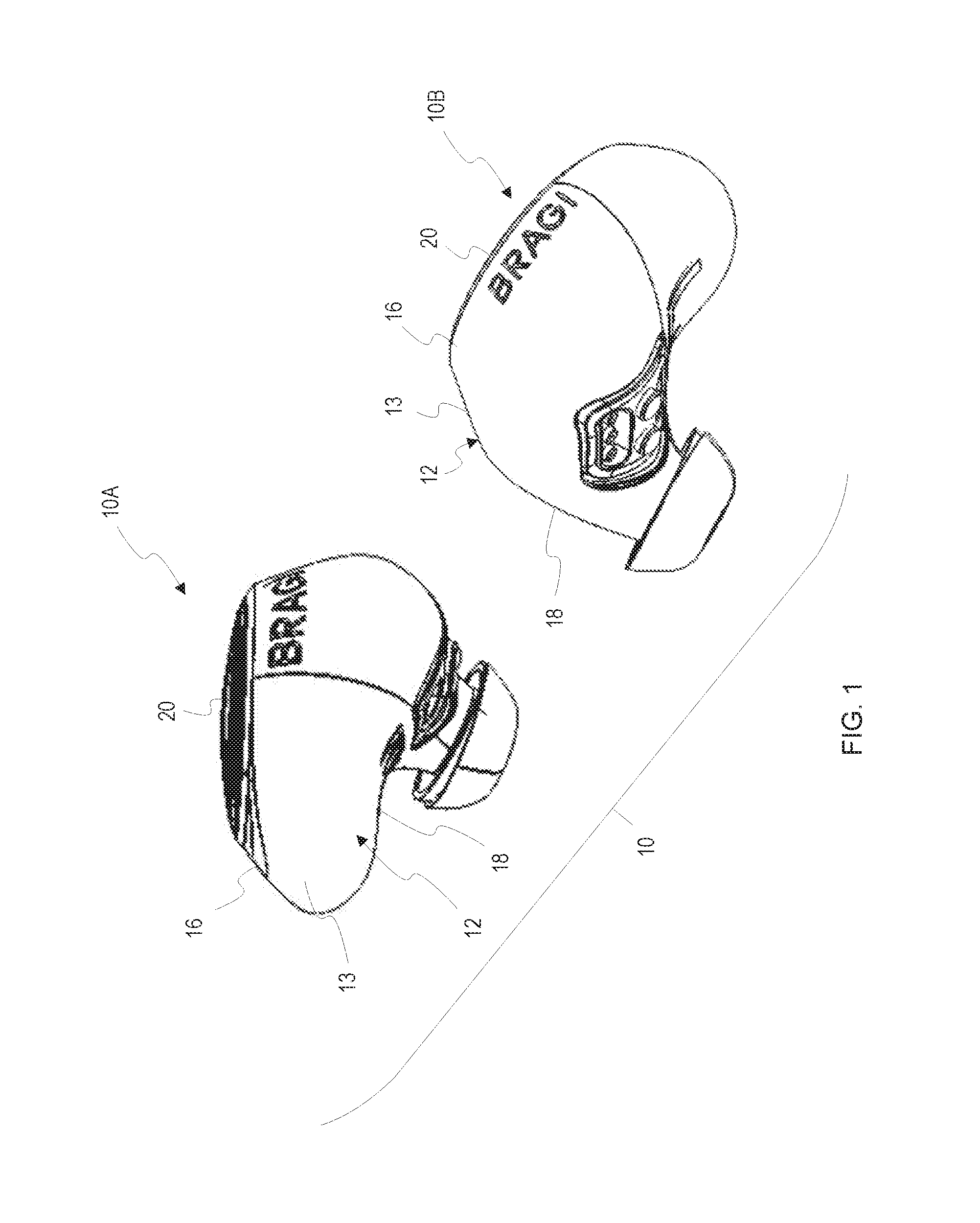
FIG. 1 illustrates one example of a system including two wearable devices in the form of left and right ear pieces which bi-directionally communicate with each other.
FIG. 2 is an exploded view of a wearable device.
FIG. 3 illustrates a printed circuit board of the wearable device positioned relative to an induction circuit/antenna.
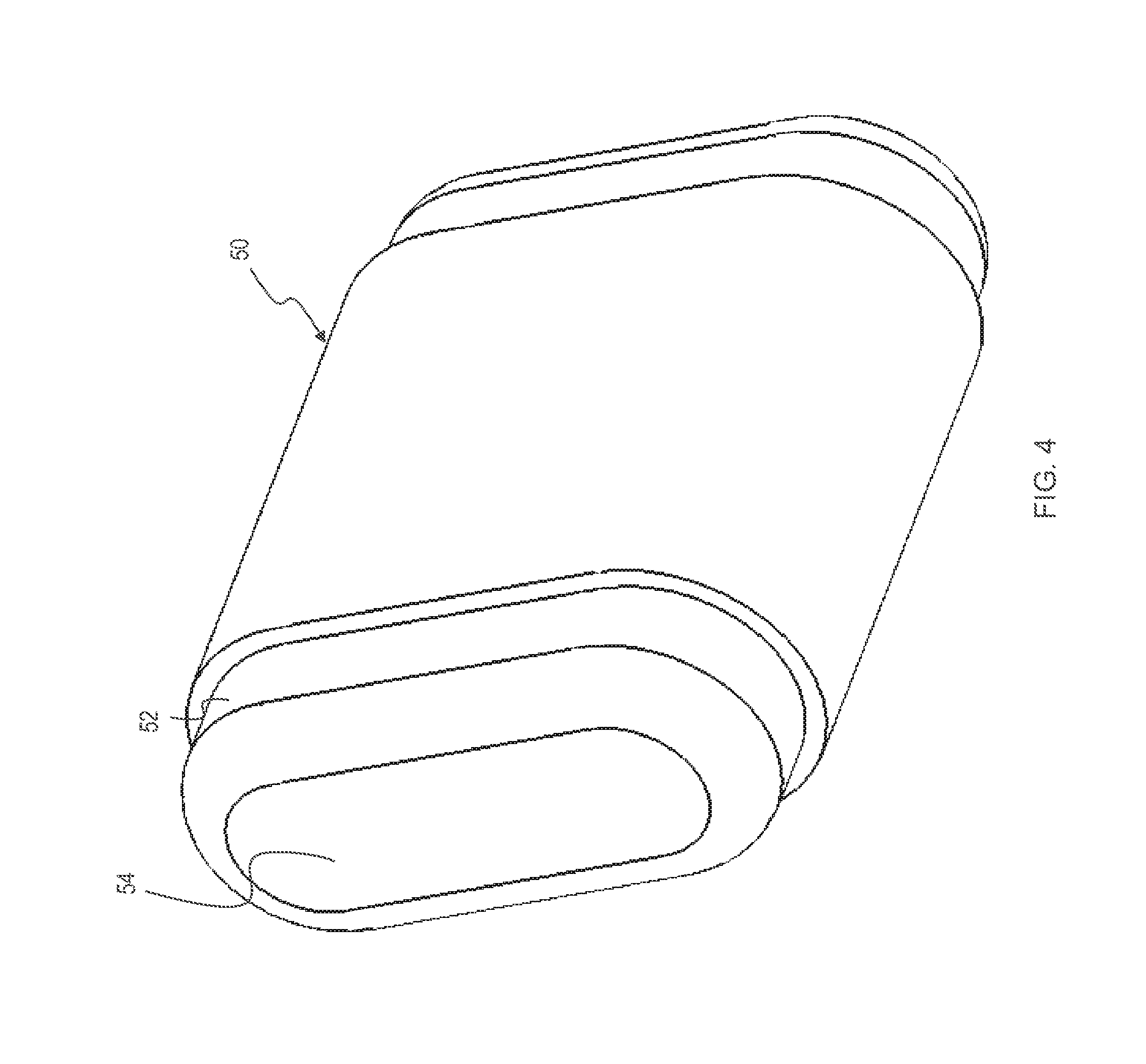
FIG. 4 illustrates a core.
FIG. 5 illustrates a core with coil turns thereon.
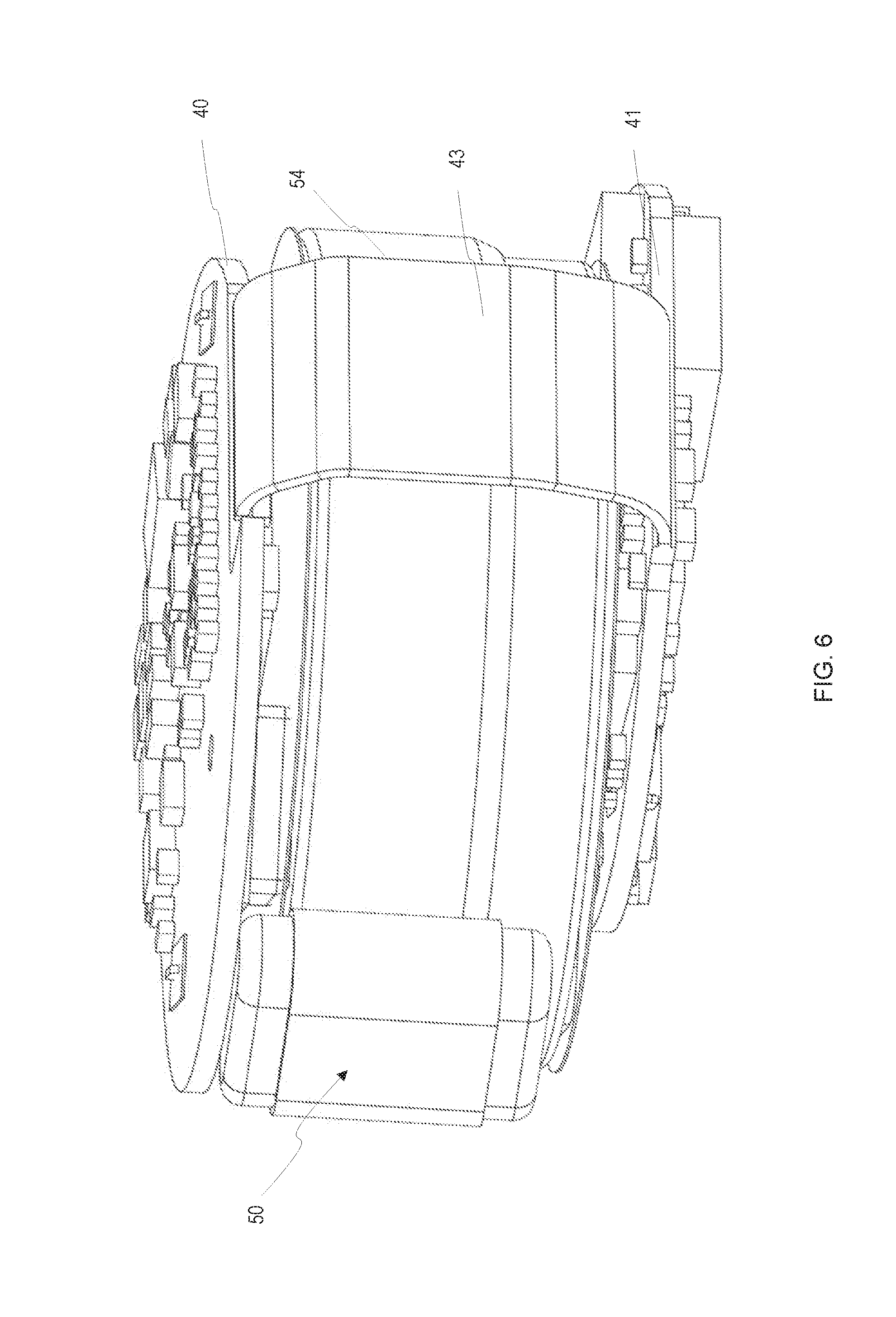
FIG. 6 illustrates printed circuit boards on opposite sides of a battery with an antenna wrapped around the battery.
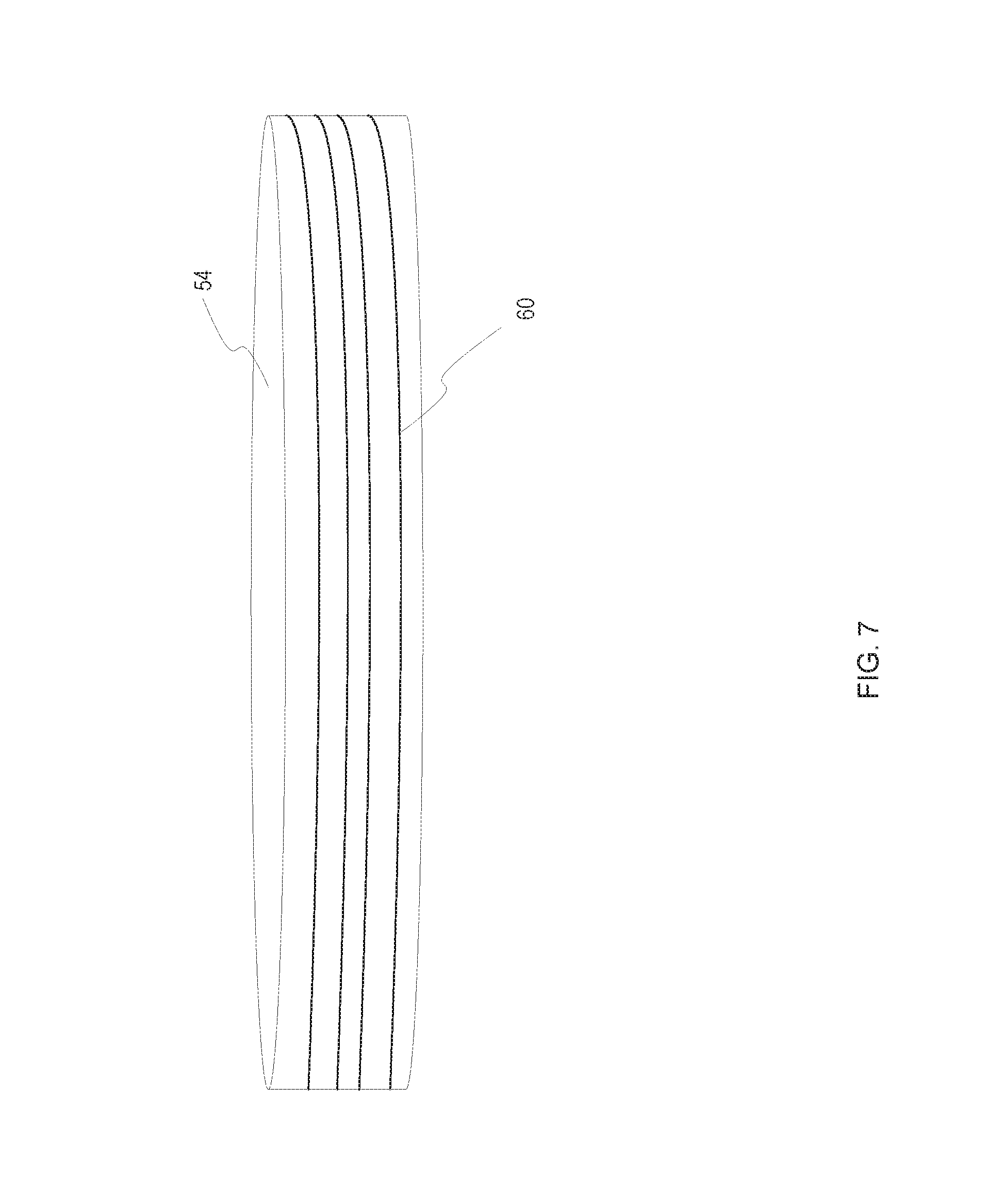
FIG. 7 illustrates another example of a battery with antenna coils wrapped around the battery.
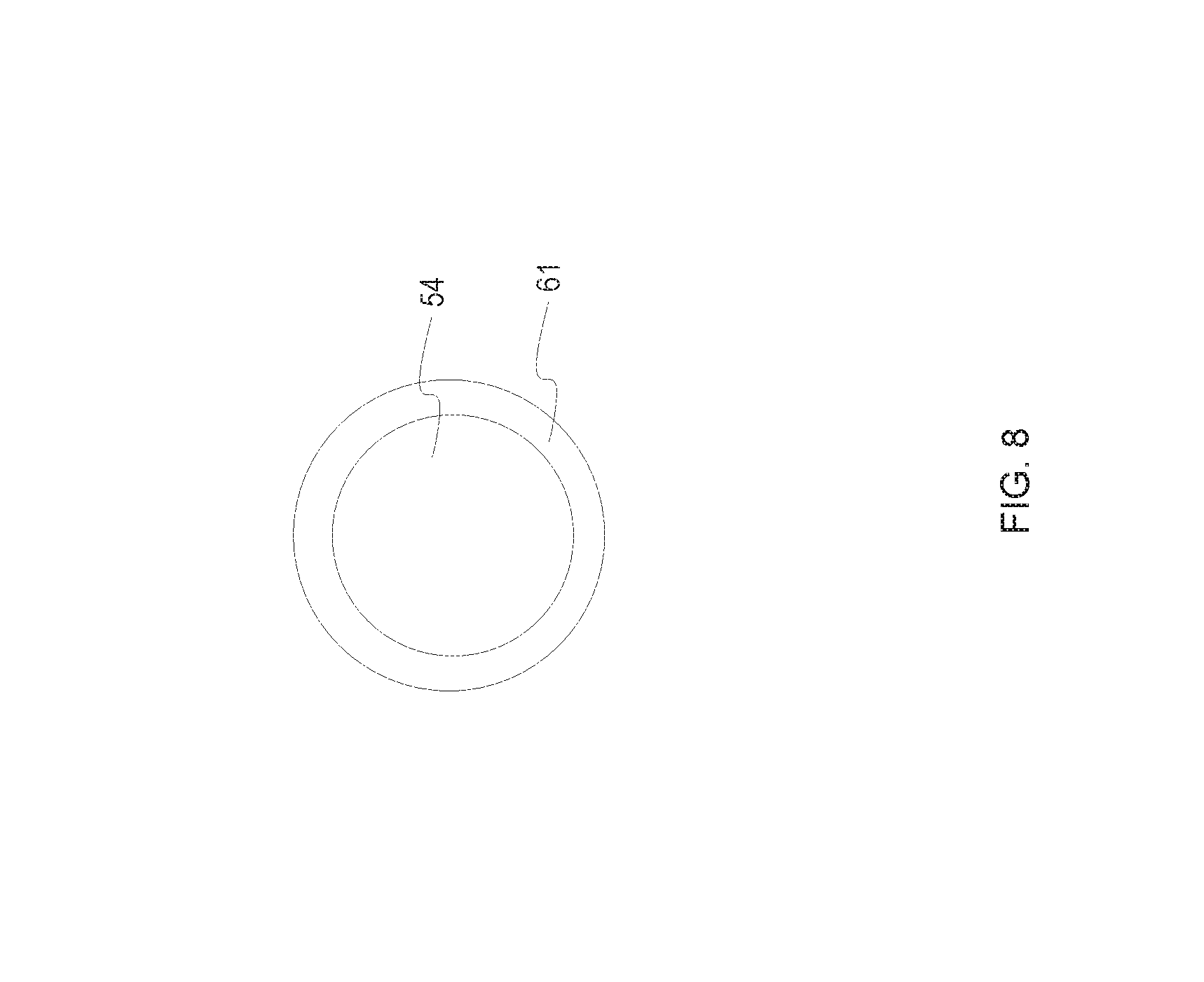
FIG. 8 and FIG. 9 illustrates an example of a spacer positioned around a battery with antenna coils wrapped around the space.
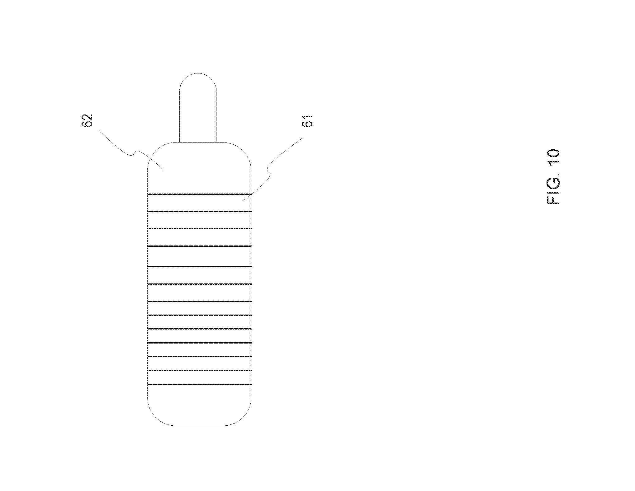
FIG. 10 illustrates a balanced armature speaker with antenna coils wrapped around the balanced armature speaker.
FIG. 11 illustrates a portion of an earpiece housing with antenna coils wrapped around tips of the ear piece housing.
DETAILED DESCRIPTION
The present invention relates to a wearable device such as an earpiece having an antenna. Although generally described herein with respect to a near field magnetic induction (NFMI) antenna for use in an ear piece within a set of ear pieces, it is to be understood the present invention is not limited to specific applications and may be used as an antenna for induction in other types of devices including other types of wearable devices.
FIG. 1. illustrates one example of a system 10 which includes a first wearable device 10A in the form of an ear piece and a second wearable device 10B in the form of an ear piece, each having an ear piece housing 12 with a central portion 13 with an upper portion 16 and a lower portion 18. A light guide assembly 20 is shown operatively connected to the housing to provide for selective illumination to provide feedback to a user. FIG. 2 provides an exploded view of the wearable device 10A. A waterproof pad 24 and protection mesh 26 are shown. In addition in the central or main portion 13 of the wearable device 10A a printed circuit board 40 is shown with a plurality of electronic components 42 mounted thereto. The plurality of electronic components 42 may include a short range transceiver configured for far field communications such as a wireless radio such as a Bluetooth transceiver, an ultra-wideband (UWB), or other type of transceiver. A near field magnetic induction (NFMI) antenna 50 is mounted at an edge or perimeter of the printed circuit board 40. The NFMI antenna 50 is mounted at a posterosuperior portion of the wearable device 10A.
The system 10 allows for near field communication of audio channels between the left and right-sided wearable devices 10A, 10B. Other types of data may also be communicated between the left and right-sided wearable devices 10A, 10B if desired including sensor information or other data.
FIG. 3 illustrates another view of the printed circuit board 40 with electronic components 42. A NFMI antenna 50 is shown mounted at an edge or perimeter of the printed circuit board 40. The printed circuit board is generally planar. Note that the NFMI antenna 50 is mounted perpendicularly or orthogonally to the top surface of printed circuit board 40 and the plurality of components 42 mounted thereto. Positioning the NFMI antenna 50 in this relationship provides for reducing electromagnetic interference. The core of the NFMI antenna 50 may be formed or a ferrite material. For example, the core of the NFMI antenna 50 may be a ferrite sheet magnetic spacer. As shown in FIG. 4, where the core of the NFMI antenna 50 includes ferrite sheet magnetic spacer 52, an exterior of the NFMI antenna 50 may be positioned over or wrapped around a battery 54. As shown in FIG. 5, a plurality of coil turns 60 may be wrapped around the battery 54 that is the core of the NFMI antenna 50. The coil turns 60 wrapped around the battery 54 (or other core) form the NFMI antenna 50.
As shown in FIG. 4, the transceiver 50 has a plurality of coil turns 60 wrapped around the ferrite material 52. As shown in FIG. 4, the coil turns 60 may be tightly wrapped with respect to one another and thus separation between individual coil turns is not shown. The transceiver 50 may be positioned adjacent to the battery 54. As shown in FIG. 5, a plurality of coil turns 60 may be wrapped around the ferrite material 52. The transceiver 50 is positioned adjacent a battery 54.
In one embodiment NFMI may be used for the communication and audio channels between the left and right sided wearable devices. Placement of the coil at the perimeter of the wearable improves the electromagnetic field, avoiding degradation from adjacent onboard electronics. This allows for optimal placement of the magnetic field for transmission and reception between the left and right wearable. The preferred embodiment allows for precise positioning within the device for optimal orientation for the electromagnetic field. Further, the preferred embodiment also allows for an NFMI antenna sufficiently powerful for the expected tasks and is straightforward in its manufacturing and assembly.
FIG. 6 illustrates printed circuit boards on opposite sides of a battery with an antenna positioned around the battery. A first printed circuit board 40 is shown as well as a second printed circuit board 41. There is a flexible connector 43 between the first printed circuit board 40 and the second printed circuit board 41 to provide electrical connections therebetween. The transceiver 50 is positioned at an outer portion of the battery and may be positioned adjacent or near to a radio transceiver on the printed circuit board 40.
FIG. 7 illustrates another example of a battery 54 with antenna coils 60 wrapped around the battery 54. In this embodiment, the battery such as the one shown in FIG. 6 is positioned between circuit boards and may be wrapped such as in a ferrite tape, but the ferrite tape need not be present. Alternatively, for example, a spacer may be used between the battery and the antenna coils with the coils wrapped around the spacer positioned around the battery. Thus, instead of the transceiver being placed next to the battery, the transceiver is formed by wrapping the coils 60 around the battery 54.
FIG. 8 illustrates an example of a top view of spacer 61 positioned around a battery 54. FIG. 9 illustrates the spacer 61 with antenna coils 60 wrapped around it (and thus around the battery about which the spacer 61 is positioned. Thus, instead of directly wrapping antenna coils 60 around a battery 54, antenna coils 60 may be wrapped around a spacer 61 which in turn is positioned around a battery 54.
FIG. 10 illustrates a balanced armature speaker 62 with antenna coils 61 wrapped around the balanced armature speaker 62. The armature speaker 62 may be positioned within the earpiece housing and this provides an alternative location for placement of the transceiver formed using the antenna coils 61.
FIG. 11 illustrates a portion of an earpiece housing with antenna coils 61 wrapped around a tip 64 of the ear piece housing.
In addition, the antenna coils may be positioned in other locations in the earpiece including around the earpiece housing or case or portions thereof. The various locations of the earpiece may be wrapped in a ferrite tape prior to wrapping the antenna coils around the location. Generally, the location should allow for a coil with circular or substantially circular cross-section to be performed.
Testing was performed on various locations for the coils to determine a range where there was 100 percent and a range where there was 0 percent reception. Testing was performed both in open air between two different NFMI transceivers as well as in active wireless earpieces. In addition, testing was performed under varying conditions such as mode of operation of the device (e.g. playing music) at different power settings. The earpiece may include as a part of the circuitry on one of the printed circuit boards a memory for storing music files which may be played back. It is noted this circuitry as well as processing circuitry and other circuitry may be the source of interference to near field communications. The results of the testing indicate the antenna may be placed at these various locations throughout the earpiece although different locations as well as other factors may result in different reliable ranges.
Therefore, a wearable device has been shown and described and a system including multiple ear pieces which communicate with one another has also been shown and described. It is to be understood the present invention contemplates numerous variations, options, and alternatives. The present invention is not to be limited to the specific embodiments and examples set forth herein.
* * * * *
References
-
en.wikipedia.org/wiki/Gamebook
-
-
-
bmwblog.com/2016/01/05/bmw-introduces-bmw-connected-the-personalized-digital-assistant
-
9to5mac.com/2015/07/21/virtualhomebutton
-
theregisterco.uk/2014/09/24/ibc_round_up_object_audio_dlnaiot
-
nuance.com/about-us/newsroom/press-releases/ing-netherlands-launches-nuance-voice-biometirics.html
D00000
D00001
D00002
D00003
D00004
D00005
D00006
D00007
D00008
D00009
D00010
D00011
XML
uspto.report is an independent third-party trademark research tool that is not affiliated, endorsed, or sponsored by the United States Patent and Trademark Office (USPTO) or any other governmental organization. The information provided by uspto.report is based on publicly available data at the time of writing and is intended for informational purposes only.
While we strive to provide accurate and up-to-date information, we do not guarantee the accuracy, completeness, reliability, or suitability of the information displayed on this site. The use of this site is at your own risk. Any reliance you place on such information is therefore strictly at your own risk.
All official trademark data, including owner information, should be verified by visiting the official USPTO website at www.uspto.gov. This site is not intended to replace professional legal advice and should not be used as a substitute for consulting with a legal professional who is knowledgeable about trademark law.