Sensor systems for absorbent articles comprising sensor gates
LaVon , et al.
U.S. patent number 10,292,112 [Application Number 14/455,088] was granted by the patent office on 2019-05-14 for sensor systems for absorbent articles comprising sensor gates. This patent grant is currently assigned to The Procter & Gamble Company. The grantee listed for this patent is The Procter & Gamble Company. Invention is credited to Jonathan Livingston Joyce, Gary Dean LaVon, Grant Edward Anders Striemer.


| United States Patent | 10,292,112 |
| LaVon , et al. | May 14, 2019 |
Sensor systems for absorbent articles comprising sensor gates
Abstract
A sensor system for detecting a property of or within an absorbent article. The system may comprise a first sensor and a first transmitter. The sensor may be disposed in or on the absorbent article. The sensor may have a first status and may be capable of changing to a second status. The first transmitter may be capable of sensing a change in status of the sensor from the first status to the second status. The first transmitter may be capable of checking the status of the sensor noncontinuously. The first transmitter may programmed to check the status of the first sensor at least every 5 minutes but not longer than every 2 hours.
| Inventors: | LaVon; Gary Dean (Liberty Township, OH), Striemer; Grant Edward Anders (Fairfield Township, OH), Joyce; Jonathan Livingston (Independence, KY) | ||||||||||
|---|---|---|---|---|---|---|---|---|---|---|---|
| Applicant: |
|
||||||||||
| Assignee: | The Procter & Gamble
Company (Cincinnati, OH) |
||||||||||
| Family ID: | 51535503 | ||||||||||
| Appl. No.: | 14/455,088 | ||||||||||
| Filed: | August 8, 2014 |
Prior Publication Data
| Document Identifier | Publication Date | |
|---|---|---|
| US 20150042489 A1 | Feb 12, 2015 | |
Related U.S. Patent Documents
| Application Number | Filing Date | Patent Number | Issue Date | ||
|---|---|---|---|---|---|
| 61863595 | Aug 8, 2013 | ||||
| Current U.S. Class: | 1/1 |
| Current CPC Class: | A61F 13/42 (20130101); A61F 13/15772 (20130101); H04W 52/22 (20130101); A61F 13/49 (20130101); A61F 2013/424 (20130101) |
| Current International Class: | A61F 13/15 (20060101); A61F 13/42 (20060101); H04W 52/22 (20090101); A61F 13/49 (20060101) |
References Cited [Referenced By]
U.S. Patent Documents
| 3848594 | November 1974 | Buell |
| 3860003 | January 1975 | Buell |
| 3911173 | October 1975 | Sprague, Jr. |
| 4022210 | May 1977 | Glassman |
| 4265245 | May 1981 | Glassman |
| 4286331 | August 1981 | Anderson |
| 4515595 | May 1985 | Kievit et al. |
| 4554662 | November 1985 | Suzuki |
| 4573986 | March 1986 | Minetola et al. |
| 4662875 | May 1987 | Hirotsu et al. |
| 4681793 | July 1987 | Linman et al. |
| 4695278 | September 1987 | Lawson |
| 4699622 | October 1987 | Toussant et al. |
| 4710189 | December 1987 | Lash |
| 4785996 | November 1988 | Ziecker et al. |
| 4795454 | January 1989 | Dragoo |
| 4808178 | February 1989 | Aziz |
| 4842666 | June 1989 | Werenicz |
| 4846815 | July 1989 | Molloy |
| 4894060 | January 1990 | Nestegard |
| 4909803 | March 1990 | Aziz et al. |
| 4940464 | July 1990 | Van Gompel et al. |
| 4946527 | August 1990 | Battrell |
| 4963140 | October 1990 | Robertson et al. |
| 5137537 | August 1992 | Herron et al. |
| 5151092 | September 1992 | Buell et al. |
| 5221274 | June 1993 | Buell et al. |
| 5242436 | September 1993 | Weil et al. |
| 5264830 | November 1993 | Kline et al. |
| 5354289 | October 1994 | Mitchell et al. |
| 5433715 | July 1995 | Tanzer et al. |
| 5469145 | November 1995 | Johnson |
| 5499978 | March 1996 | Buell et al. |
| 5507736 | April 1996 | Clear et al. |
| 5554145 | September 1996 | Roe et al. |
| 5569234 | October 1996 | Buell et al. |
| 5571096 | November 1996 | Dobrin et al. |
| 5580411 | December 1996 | Nease et al. |
| 5591152 | January 1997 | Buell et al. |
| 5607414 | March 1997 | Richards et al. |
| 5700254 | December 1997 | McDowall et al. |
| 5709222 | January 1998 | Davallou |
| 5714156 | February 1998 | Schmidt et al. |
| 5838240 | November 1998 | Johnson |
| 5865823 | February 1999 | Curro |
| 5902222 | May 1999 | Wessman |
| 5938648 | August 1999 | LaVon et al. |
| 5959535 | September 1999 | Remsburg |
| 6004306 | December 1999 | Robles et al. |
| 6160198 | March 2000 | Roe et al. |
| 6093869 | July 2000 | Roe et al. |
| 6121509 | September 2000 | Ashraf et al. |
| 6203496 | March 2001 | Gael et al. |
| 6372951 | April 2002 | Ovanesyan et al. |
| 6384296 | May 2002 | Roe et al. |
| 6432098 | August 2002 | Kline et al. |
| 6501002 | December 2002 | Roe et al. |
| 6534149 | March 2003 | Daley et al. |
| 6603403 | August 2003 | Jeutter et al. |
| 6609068 | August 2003 | Cranley |
| 6617488 | September 2003 | Springer |
| 6632504 | October 2003 | Gillespie et al. |
| 6645190 | November 2003 | Olson et al. |
| 6645569 | November 2003 | Cramer et al. |
| 6863933 | March 2005 | Cramer et al. |
| 6946585 | September 2005 | Brown |
| 7002054 | February 2006 | Allen et al. |
| 7049969 | May 2006 | Tamai |
| 7112621 | September 2006 | Rohrbaugh et al. |
| 7174774 | February 2007 | Pawar |
| 7241627 | July 2007 | Wilhelm et al. |
| 7250547 | July 2007 | Hofmeister et al. |
| 7295125 | November 2007 | Gabriel |
| 7355090 | April 2008 | Alex, III et al. |
| 7394391 | July 2008 | Long |
| 7449614 | November 2008 | Alex, III |
| 7477156 | January 2009 | Long et al. |
| 7489252 | February 2009 | Long et al. |
| 7498478 | March 2009 | Long et al. |
| 7504550 | March 2009 | Tippey et al. |
| 7524195 | April 2009 | Ales et al. |
| 7537832 | May 2009 | Carlucci et al. |
| 7595734 | September 2009 | Long et al. |
| 7642396 | January 2010 | Alex, III et al. |
| 7649125 | January 2010 | Ales, III et al. |
| 7659815 | February 2010 | Cohen et al. |
| 7667806 | February 2010 | Ales et al. |
| 7700820 | April 2010 | Tippey et al. |
| 7700821 | April 2010 | Ales, III et al. |
| 7737322 | June 2010 | Alex, III et al. |
| 7753691 | July 2010 | Ales et al. |
| 7760101 | July 2010 | Ales, III et al. |
| 7786341 | August 2010 | Schneider et al. |
| 7789869 | September 2010 | Berland et al. |
| 7803319 | September 2010 | Yang et al. |
| 7812731 | October 2010 | Bunza et al. |
| 7834235 | November 2010 | Long et al. |
| 7835925 | November 2010 | Roe et al. |
| 7846383 | December 2010 | Song |
| 7850470 | December 2010 | Ales et al. |
| 7855653 | December 2010 | Rondoni et al. |
| 7879392 | February 2011 | Wenzel et al. |
| 7956754 | April 2011 | Long |
| 7946869 | May 2011 | Ales et al. |
| 7973210 | July 2011 | Long et al. |
| 8044258 | October 2011 | Hietpas |
| 8053625 | November 2011 | Nhan et al. |
| 8057454 | November 2011 | Long et al. |
| 8058194 | November 2011 | Nhan et al. |
| 8101813 | January 2012 | Ales et al. |
| 8111165 | February 2012 | Ortega et al. |
| 8115643 | February 2012 | Wada et al. |
| 8172982 | May 2012 | Ales et al. |
| 8173380 | May 2012 | Yang et al. |
| 8183876 | May 2012 | Wada et al. |
| 8196270 | June 2012 | Mandzsu |
| 8196809 | June 2012 | Thorstensson |
| 8207394 | June 2012 | Feldkamp et al. |
| 8215973 | July 2012 | Ales et al. |
| 8222476 | July 2012 | Song et al. |
| 8237572 | August 2012 | Clement et al. |
| 8248249 | August 2012 | Clement et al. |
| 8264362 | September 2012 | Ales et al. |
| 8274393 | September 2012 | Ales et al. |
| 8299317 | October 2012 | Tippey et al. |
| 8304598 | November 2012 | Masbacher et al. |
| 8314284 | November 2012 | Novello |
| 8334226 | December 2012 | Nhan et al. |
| 8334425 | December 2012 | Ales et al. |
| 8338659 | December 2012 | Collins et al. |
| 8350694 | January 2013 | Trundle |
| 8372242 | February 2013 | Ales et al. |
| 8372766 | February 2013 | Nhan et al. |
| 8378167 | February 2013 | Allen et al. |
| 8381536 | February 2013 | Nhan et al. |
| 8384378 | February 2013 | Feldkamp et al. |
| 8395014 | March 2013 | Helmer et al. |
| 8416088 | April 2013 | Ortega et al. |
| 8431766 | April 2013 | Lonero |
| 8440877 | May 2013 | Collins et al. |
| 8452388 | May 2013 | Feldkamp et al. |
| 8471715 | June 2013 | Solazzo et al. |
| 8507746 | August 2013 | Ong et al. |
| 8546639 | October 2013 | Wada et al. |
| 8563801 | October 2013 | Berland et al. |
| 8570175 | October 2013 | Rahimi |
| 8604268 | December 2013 | Cohen et al. |
| 8623292 | January 2014 | Song et al. |
| 8628506 | January 2014 | Ales, III et al. |
| 8882731 | January 2014 | Suzuki et al. |
| 8642832 | February 2014 | Ales et al. |
| 8697933 | April 2014 | Ales, III et al. |
| 8697934 | April 2014 | Nhan et al. |
| 8697935 | April 2014 | Daanen |
| 8698641 | April 2014 | Abraham et al. |
| 8742198 | June 2014 | Wei et al. |
| 8773117 | July 2014 | Feldkamp et al. |
| 8779785 | July 2014 | Wada et al. |
| 8785716 | July 2014 | Schafer et al. |
| 8816149 | August 2014 | Richardson et al. |
| 8866052 | October 2014 | Nhan et al. |
| 8866624 | October 2014 | Ales et al. |
| 8884769 | November 2014 | Novak |
| 8889944 | November 2014 | Abraham et al. |
| 8920731 | December 2014 | Nhan et al. |
| 8933291 | January 2015 | Wei et al. |
| 8933292 | January 2015 | Abraham et al. |
| 8962909 | February 2015 | Groosman et al. |
| 8975465 | March 2015 | Hong et al. |
| 8978452 | March 2015 | Johnson et al. |
| 8988231 | March 2015 | Chen |
| 9018434 | April 2015 | Ruman |
| 9034593 | May 2015 | Martin et al. |
| 9070060 | June 2015 | Forster |
| 9072634 | July 2015 | Hundorf et al. |
| 9211218 | December 2015 | Rinnert et al. |
| 9295593 | March 2016 | Van Malderen |
| 9380977 | July 2016 | Abir |
| 2002/0021220 | February 2002 | Dreyer |
| 2002/0070864 | June 2002 | Jeutter et al. |
| 2003/0105190 | June 2003 | Diehl et al. |
| 2003/0148684 | August 2003 | Cramer et al. |
| 2003/0208133 | November 2003 | Mault |
| 2004/0064114 | April 2004 | David |
| 2004/0106202 | June 2004 | Zainiev et al. |
| 2004/0127867 | July 2004 | Odorzynski et al. |
| 2004/0220538 | November 2004 | Panopoulos |
| 2004/0236302 | November 2004 | Wilhelm |
| 2004/0254549 | December 2004 | Olson et al. |
| 2005/0008839 | January 2005 | Cramer et al. |
| 2005/0033250 | February 2005 | Collette |
| 2005/0065487 | March 2005 | Graef et al. |
| 2005/0099294 | May 2005 | Bogner |
| 2005/0124947 | June 2005 | Fernfors |
| 2005/0137542 | June 2005 | Underhill et al. |
| 2005/0195085 | September 2005 | Cretu-Petra |
| 2006/0061477 | March 2006 | Yeh |
| 2006/0069362 | March 2006 | Odorzynski |
| 2006/0195068 | August 2006 | Lawando |
| 2006/0222675 | October 2006 | Sabnis et al. |
| 2006/0264861 | November 2006 | LaVon |
| 2007/0044805 | March 2007 | Wedler |
| 2007/0055210 | March 2007 | Kao |
| 2007/0142797 | June 2007 | Long et al. |
| 2007/0156106 | July 2007 | Klofta |
| 2007/0185467 | August 2007 | Klofta et al. |
| 2007/0233027 | October 2007 | Roe et al. |
| 2007/0252710 | November 2007 | Long |
| 2007/0252713 | November 2007 | Rondoni et al. |
| 2007/0255241 | November 2007 | Weber et al. |
| 2007/0255242 | November 2007 | Ales, III et al. |
| 2007/0270774 | November 2007 | Bergman et al. |
| 2008/0021423 | January 2008 | Klofta |
| 2008/0021428 | January 2008 | Klofta et al. |
| 2008/0052030 | February 2008 | Olson et al. |
| 2008/0054408 | March 2008 | Tippey et al. |
| 2008/0057693 | March 2008 | Tippey et al. |
| 2008/0058740 | March 2008 | Sullivan et al. |
| 2008/0058741 | March 2008 | Long et al. |
| 2008/0082062 | April 2008 | Cohen et al. |
| 2008/0082063 | April 2008 | Ales |
| 2008/0132859 | June 2008 | Pires |
| 2008/0147031 | June 2008 | Long et al. |
| 2008/0208155 | August 2008 | LaVon |
| 2008/0234644 | September 2008 | Hansson et al. |
| 2008/0266117 | October 2008 | Song et al. |
| 2008/0266122 | October 2008 | Ales et al. |
| 2008/0266123 | October 2008 | Ales |
| 2008/0269707 | October 2008 | Song |
| 2008/0300559 | December 2008 | Gustafson |
| 2008/0312622 | December 2008 | Hundorf et al. |
| 2009/0058072 | March 2009 | Weber et al. |
| 2009/0062756 | March 2009 | Long et al. |
| 2009/0124990 | May 2009 | Feldkamp et al. |
| 2009/0155753 | June 2009 | Ales et al. |
| 2009/0326409 | December 2009 | Cohen et al. |
| 2010/0013778 | January 2010 | Liu |
| 2010/0030173 | February 2010 | Song et al. |
| 2010/0145294 | June 2010 | Song et al. |
| 2010/0152688 | June 2010 | Handwerker et al. |
| 2010/0159599 | June 2010 | Song et al. |
| 2010/0159611 | June 2010 | Song et al. |
| 2010/0160882 | June 2010 | Lowe |
| 2010/0164733 | July 2010 | Ales |
| 2010/0168694 | July 2010 | Gakhar et al. |
| 2010/0168702 | July 2010 | Ales, III et al. |
| 2010/0241094 | September 2010 | Sherron |
| 2010/0277324 | November 2010 | Yeh |
| 2011/0251038 | October 2011 | LaVon |
| 2011/0298597 | December 2011 | Kaihori |
| 2012/0061016 | March 2012 | Lavon |
| 2012/0116337 | May 2012 | Ales |
| 2012/0130330 | May 2012 | Wilson et al. |
| 2012/0157947 | June 2012 | Nhan et al. |
| 2012/0172824 | July 2012 | Khaknazarov |
| 2012/0190956 | July 2012 | Connolly |
| 2012/0206265 | August 2012 | Solazzo |
| 2012/0215190 | August 2012 | Kawashima |
| 2012/0225200 | September 2012 | Mandzsu |
| 2012/0245541 | September 2012 | Suzuki |
| 2012/0282681 | November 2012 | Teixeira et al. |
| 2012/0299721 | November 2012 | Jones |
| 2012/0310190 | December 2012 | LaVon et al. |
| 2012/0310192 | December 2012 | Suzuki et al. |
| 2012/0323194 | December 2012 | Suzuki et al. |
| 2013/0012896 | January 2013 | Suzuki et al. |
| 2013/0018340 | January 2013 | Abraham et al. |
| 2013/0023786 | January 2013 | Mani et al. |
| 2013/0041334 | February 2013 | Prioleau |
| 2013/0076509 | March 2013 | Ahn |
| 2013/0110061 | May 2013 | Abraham et al. |
| 2013/0110063 | May 2013 | Abraham |
| 2013/0131618 | May 2013 | Abraham et al. |
| 2013/0151186 | June 2013 | Feldkamp |
| 2013/0161380 | June 2013 | Joyce et al. |
| 2013/0162402 | June 2013 | Amann et al. |
| 2013/0162403 | June 2013 | Stiemer et al. |
| 2013/0162404 | June 2013 | Stiemer et al. |
| 2013/0165809 | June 2013 | Abir |
| 2013/0261409 | October 2013 | Pathak |
| 2013/0303867 | November 2013 | Elfstrom et al. |
| 2013/0307570 | November 2013 | Bosaeus et al. |
| 2013/0321007 | December 2013 | Elfstrom et al. |
| 2013/0324955 | December 2013 | Wong et al. |
| 2014/0014716 | January 2014 | Joyce et al. |
| 2014/0015644 | January 2014 | Amann et al. |
| 2014/0015645 | January 2014 | Stiemer et al. |
| 2014/0022058 | January 2014 | Stiemer et al. |
| 2014/0062663 | March 2014 | Bourilkov et al. |
| 2014/0121487 | May 2014 | Faybishenko et al. |
| 2014/0152442 | June 2014 | Li |
| 2014/0155850 | June 2014 | Shah et al. |
| 2014/0155851 | June 2014 | Ales et al. |
| 2014/0163502 | June 2014 | Arzti et al. |
| 2014/0188063 | July 2014 | Nhan et al. |
| 2014/0198203 | July 2014 | Vardi |
| 2014/0200538 | July 2014 | Euliano et al. |
| 2014/0241954 | August 2014 | Phillips et al. |
| 2014/0242613 | August 2014 | Takeuchi et al. |
| 2014/0242715 | August 2014 | Nhan et al. |
| 2014/0266736 | September 2014 | Cretu-Petra |
| 2014/0329212 | November 2014 | Ruman et al. |
| 2014/0329213 | November 2014 | Ruman et al. |
| 2014/0363354 | December 2014 | Phillips et al. |
| 2015/0025347 | January 2015 | Song |
| 2015/0042489 | February 2015 | LaVon |
| 2015/0112202 | April 2015 | Abir |
| 2015/0130637 | May 2015 | Sengstaken, Jr. |
| 2015/0150732 | June 2015 | Abir |
| 2015/0157512 | June 2015 | Abir |
| 2015/0317684 | November 2015 | Abir |
| 0 149 880 | May 1984 | EP | |||
| 149880 | Jul 1985 | EP | |||
| 1 216 673 | Oct 2005 | EP | |||
| 1 542 635 | Apr 2012 | EP | |||
| 2679209 | Jan 2014 | EP | |||
| 2740450 | Jun 2014 | EP | |||
| 2 491 899 | Jul 2014 | EP | |||
| 2002/022687 | Jan 2002 | JP | |||
| 2002/143199 | May 2002 | JP | |||
| 2003/190209 | Jul 2003 | JP | |||
| 2004/230135 | Aug 2004 | JP | |||
| 2006/296566 | Nov 2006 | JP | |||
| WO 95/10996 | Apr 1995 | WO | |||
| WO 95/11652 | May 1995 | WO | |||
| WO 95/016746 | Jun 1995 | WO | |||
| WO 99/034841 | Jul 1999 | WO | |||
| WO 99/34842 | Jul 1999 | WO | |||
| WO 2000/59430 | Oct 2000 | WO | |||
| WO 02/064877 | Aug 2002 | WO | |||
| WO 02/067809 | Sep 2002 | WO | |||
| WO 2007/122524 | Nov 2007 | WO | |||
| WO 2008/155699 | Dec 2008 | WO | |||
| WO 2010/123364 | Oct 2010 | WO | |||
| WO 2010/123425 | Oct 2010 | WO | |||
| WO 2011/013874 | Feb 2011 | WO | |||
| WO 2012/052172 | Apr 2012 | WO | |||
| WO 2012/084925 | Jun 2012 | WO | |||
| WO 2012/126507 | Sep 2012 | WO | |||
| WO 2012/166765 | Dec 2012 | WO | |||
| WO 2013/003905 | Jan 2013 | WO | |||
| WO 2013/016765 | Feb 2013 | WO | |||
| WO 2013/061963 | May 2013 | WO | |||
| WO 2013/091707 | Jun 2013 | WO | |||
| WO 2013/091728 | Jun 2013 | WO | |||
| WO 2013/095222 | Jun 2013 | WO | |||
| WO 2013/095226 | Jun 2013 | WO | |||
| WO 2013/095230 | Jun 2013 | WO | |||
| WO 2013/095231 | Jun 2013 | WO | |||
| WO 2013/097899 | Jul 2013 | WO | |||
| WO 2013/181436 | Dec 2013 | WO | |||
| WO 2013/185419 | Dec 2013 | WO | |||
| WO 2013/189284 | Dec 2013 | WO | |||
| WO 2014/035302 | Mar 2014 | WO | |||
| WO 2014/035340 | Mar 2014 | WO | |||
| WO 2014/122169 | Aug 2014 | WO | |||
| WO 2014/137671 | Sep 2014 | WO | |||
| WO 2014/146693 | Sep 2014 | WO | |||
| WO 2014/146694 | Sep 2014 | WO | |||
| WO 2014/148957 | Sep 2014 | WO | |||
| WO 2014/177200 | Nov 2014 | WO | |||
| WO 2014/177203 | Nov 2014 | WO | |||
| WO 2014/177204 | Nov 2014 | WO | |||
| WO 2014/177205 | Nov 2014 | WO | |||
| WO 2014/178763 | Nov 2014 | WO | |||
| WO 2014/192978 | Dec 2014 | WO | |||
| WO 2015/003712 | Jan 2015 | WO | |||
| WO 2015/068124 | May 2015 | WO | |||
| WO 2015/102084 | Jul 2015 | WO | |||
| WO 2015/102085 | Jul 2015 | WO | |||
Other References
|
Reassessment of Federal Communications Commission Radio Frequency Exposure Limits and Policies; Mar. 29, 2013. cited by examiner . International Search Report and Written Opinion, PCT/US2014/050083, dated Oct. 28, 2014. cited by applicant. |
Primary Examiner: Lim; Steven
Assistant Examiner: Adnan; Muhammad
Attorney, Agent or Firm: Alexander; Richard L.
Parent Case Text
CROSS REFERENCE TO RELATED APPLICATIONS
This application claims the benefit, under 35 USC 119(e), to U.S. Provisional Patent Application No. 61/863,595 filed on Aug. 8, 2013, which is herein incorporated by reference in its entirety.
Claims
What is claimed is:
1. A sensor system for detecting a property of or within an absorbent article, comprising: an absorbent article comprising a front region, a back region, and a crotch region, a transverse axis and a longitudinal axis; the absorbent article further comprising an elongate housing comprising a first sensor and a second sensor; a first transmitter; wherein the elongate housing is disposed such that each of the first and second sensors are disposed forward of the transverse axis of the absorbent article; wherein no sensor of the sensor system and no portion of the housing is disposed rearward of the transverse axis; wherein at least one of the first and second sensors overlaps with the longitudinal axis; wherein the elongate housing is disposed along a longitudinal axis of the absorbent article, and wherein the elongate carrier layer is disposed on a garment-facing, exterior surface of the absorbent article, and wherein the elongate housing comprises at least one of hooks and loops; wherein the first sensor has a first status and is capable of changing to a second status; wherein the second sensor has a third status and is capable of changing to a fourth status; wherein at least one of the first and second sensors are capable of sensing a color change through the garment-facing, exterior surface of the absorbent article; wherein the first transmitter is capable of transmitting a signal when a change in status of the first sensor from the first status to the second status has occurred; wherein the first transmitter is capable of transmitting a signal when a change in status of the second sensor from the third status to the fourth status has occurred; wherein the first transmitter is capable of operating at a first power level during an assessment operation and a second power level, higher than the first power level, during a transmission operation; and wherein the first transmitter emits an average of less than 1 mW/cm.sup.2 per hour, and wherein the first transmitter emits non-continuously when signaling to a remote device.
2. The sensor system of claim 1, wherein the sensor system comprises a second transmitter.
3. The sensor system of claim 2, wherein the first transmitter is capable of sending a signal to a remote device that comprises the second transmitter.
4. The sensor system of claim 3, wherein the first transmitter is programmed to send the signal to the remote device after the first sensor has the second status.
5. The sensor system of claim 2, wherein the first transmitter is programmed to send the signal to the remote device after the second sensor has the fourth status.
6. The sensor system of claim 1, wherein the first transmitter is capable of being manually overridden by the user with a mobile application interface either from an application opening or by manually pressing a button on an application graphical user interface ("GUI") to check a current status of the first and/or second sensors.
7. The sensor system of claim 1, wherein the first sensor is disposed in the front region.
8. The sensor system of claim 5, wherein the second sensor is disposed in the front region, laterally outboard of the first sensor.
9. The sensor system of claim 1, further comprising a graphic for properly placing the first and second sensors.
10. The sensor system of claim 1, wherein the second and fourth status occur due to different stimuli.
11. The sensor system of claim 10, wherein at least one of the different stimuli is vapor.
12. The sensor system of claim 10, wherein at least one of the different stimuli is temperature.
13. The sensor system of claim 10, wherein at least one of the different stimuli is mechanical.
14. The sensor system of claim 13, where in the mechanical stimulus is selected from one or a combination of strain, stress, and mechanical failure.
15. The sensor system of claim 10, wherein at least one of the different stimuli is acidity/basicity ("pH").
16. The sensor system of claim 10, wherein at least one of the different stimuli is a biological element.
17. The sensor system of claim 16, wherein the biological element is blood, biomarkers, and proteins.
18. The sensor system of claim 10, wherein at least one of the different stimuli is a chemical.
19. The sensor system of claim 13, wherein the chemical/analyte is selected from one or a combination of ammonia, urea, chloride, sodium, potassium, sugar, and creatinine.
20. The sensor system of claim 1, wherein the first transmitter emits for less than 10 seconds when signaling to a remote device.
21. The sensor system of claim 1, wherein the first transmitter emits for less than 5 seconds when signaling to a remote device.
22. The sensor system of claim 1, wherein the first transmitter emits for less than 2 seconds when signaling to a remote device.
23. The sensor system of claim 1, wherein the first transmitter emits an average of less than 500 pW/cm2 per hour.
24. The sensor system of claim 1, wherein the first transmitter emits an average of less than 50 pW/cm2 per hour.
25. The sensor system of claim 1, wherein the first transmitter emits an average of less than 20 pW/cm2 per hour.
26. A sensor system for detecting a property of or within an absorbent article, comprising: an absorbent article comprising a front region, a back region, and a crotch region, a transverse axis and a longitudinal axis; the absorbent article further comprising an elongate housing comprising a first sensor and a second sensor; a first transmitter; wherein the elongate housing is disposed such that each of the first and second sensors are disposed forward of the transverse axis of the absorbent article; wherein the elongate housing is disposed along a longitudinal axis of the absorbent article, and wherein the elongate housing is disposed on a garment-facing, exterior surface of the absorbent article, and wherein the elongate housing comprises at least one of hooks and loops; wherein at least one of the first and second sensors are capable of sensing a color change through the garment-facing, exterior surface of the absorbent article; wherein the first transmitter is capable of transmitting a signal when the at least one of the first and second sensors senses a color change through the garment-facing, exterior surface of the absorbent article; wherein the first transmitter is capable of operating at a first power level during an assessment operation and a second power level, higher than the first power level, during a transmission operation; and wherein the first transmitter emits an average of less than 1 mW/cm.sup.2 per hour, and wherein the first transmitter emits non-continuously when signaling to a remote device; a graphic for properly placing the elongate housing on the garment-facing, exterior surface of the absorbent article, such that neither the elongate housing nor the first and second sensors are in direct contact with the wearer.
Description
FIELD
In general, embodiments of the present disclosure relate to sensors for use with absorbent articles. In particular, embodiments of the present disclosure relate to sensor systems comprising a transmitter that utilizes one or more sensors to manage the amount of energy it emits.
BACKGROUND
The art discloses many different types of sensors that are integral with or attached to an absorbent article. These sensors are used to monitor wetness, temperature, etc. These sensors normally comprise a sensor component and a transmitting component. The transmitting component may send signals to a remote device, such as a cell phone or a remote, e.g. mobile, receiver, etc. One of the concerns with many of these designs is the amount of energy emitted by the transmitter, since many of these systems place the transmitter on or near the baby--and often around the genitals. Some transmitters emit energy constantly. In addition, some systems having sensors and a power source comprise sensors that are constantly under power. Many of the sensors are also placed in the genital area of the absorbent article and therefore emit some level of electrical energy in the genital area. From a functionality and power conservation standpoint, it is often not necessary to continually check for a change of state (e.g., within the absorbent article, such as an insult of urine and/or fecal matter). In fact, intermittent checks, for example 1 second out of 10 seconds, will provide a level of accuracy sufficient for many applications and will reduce exposure 10 fold. Some sensors may be able to detect a change in state with as little as a few milliseconds potentially reducing the exposure by more than 100 times potentially reducing the exposure by as much as 1000 times.
It is a goal to overcome the challenges mentioned above. Particularly, one object of the present disclosure is to create sensor systems having one or more sensors such that the sensor system can use low energy to check on the various sensors before initiating transmission of a stronger signal to a remote device. Further, it is an object of the present disclosure to avoid sending any signal to a second or third sensor if the first sensor is of a certain status. It is also an object of the present disclosure to use a single sensor with multiple leads that can collect information from multiple parts of the absorbent article. All of these objects help to minimize exposing the wearer of absorbent articles to energy emitted by the sensor system.
SUMMARY
A sensor system for detecting a property of or within an absorbent article. The absorbent article may comprise a front and back, a first sensor and a second sensor, and a transmitter. The first and second sensors may be disposed in or on the absorbent article. The first sensor may have a first status and may be capable of changing to a second status. The second sensor may have a third status and may be capable of changing to a fourth status. The first transmitter may be capable of sensing a change in status of the first sensor from the first status to the second status. The first transmitter may be capable of sensing a change in status of the second sensor from the third status to a fourth status. The first transmitter may be programmed to send a signal to check the status of the first sensor noncontinuously. And, the first transmitter may be programmed to send a signal to check the status of the second sensor only once the first sensor has the second status.
A sensor system for detecting a property of or within an absorbent article. The system may comprise a first sensor and a first transmitter. The sensor may be disposed in or on the absorbent article. The sensor may have a first status and may be capable of changing to a second status. The first transmitter may be capable of sensing a change in status of the sensor from the first status to the second status. The first transmitter may be capable of checking the status of the sensor noncontinuously. The first transmitter may be programmed to check the status of the first sensor at least every 5 minutes but not longer than every 0.5, 1, 1.5, or 2 hours.
BRIEF DESCRIPTION OF THE DRAWINGS
FIG. 1A illustrates a perspective view a pant-type absorbent article with a sensor in the front, according to embodiments of the present disclosure.
FIG. 1B illustrates a perspective view a pant-type absorbent article with a sensor in the back, according to embodiments of the present disclosure.
FIG. 1C illustrates a top plan view of the inner (wearer-facing) surface of a pant-type absorbent article opened and laid flat with a plurality of sensors, according to embodiments of the present disclosure.
FIG. 2 illustrates a perspective view of a pant-type absorbent article with a sensor in the front, according to embodiments of the present disclosure.
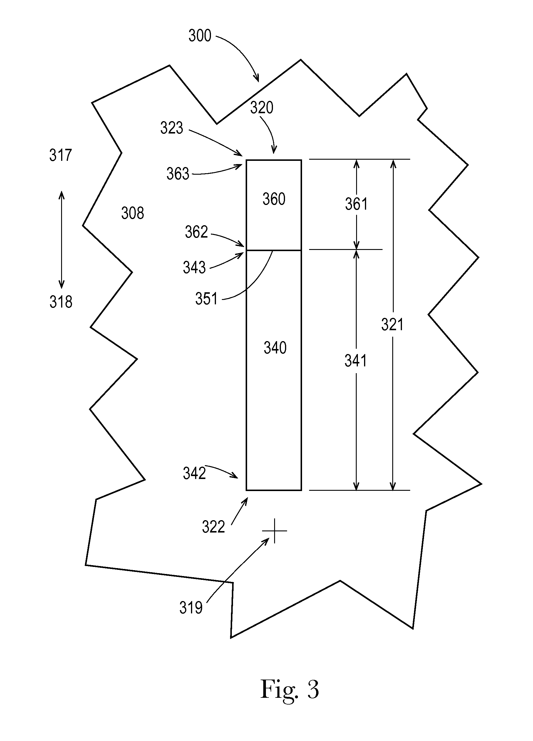
FIG. 3 illustrates a portion of an absorbent article with a sensor having a first sensing area and a second sensing area, according to embodiments of the present disclosure.
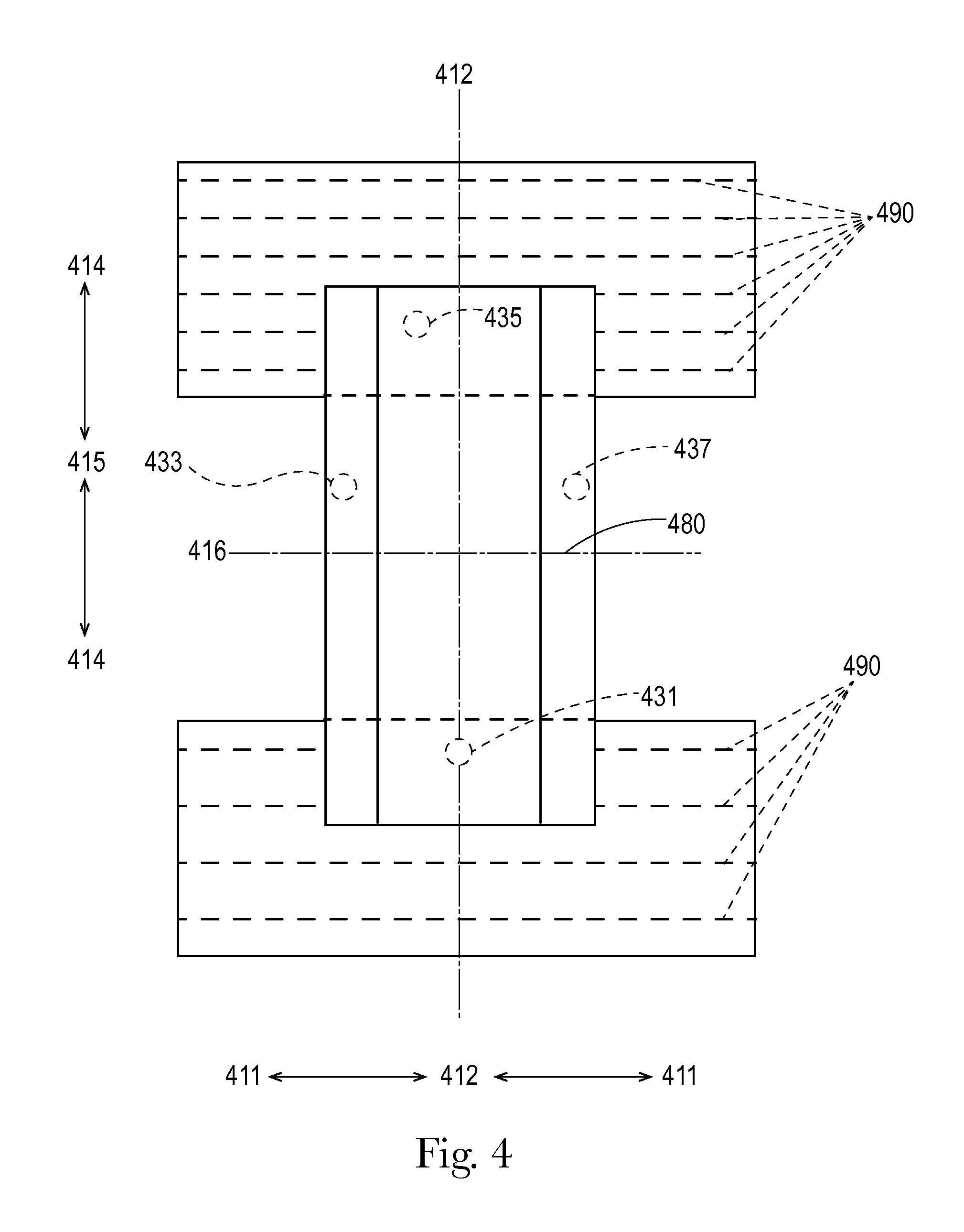
FIG. 4 illustrates a top plan view of the inner (wearer-facing) surface of a pant-type absorbent article opened and laid flat with sensors disposed at different locations, including the front, back, and cuffs, according to embodiments of the present disclosure.
FIG. 5 illustrates a perspective view of a pant-type absorbent article with a sensor comprising leads according to embodiments of the present disclosure.
DETAILED DESCRIPTION
Sensors of the present disclosure may be used with various absorbent articles and/or auxiliary articles to make a sensor system.
Absorbent Article
The absorbent article may be one for personal wear, including but not limited to diapers, training pants, feminine hygiene products, incontinence products, medical garments, surgical pads and bandages, other personal care or health care garments, and the like. Various materials and methods for constructing absorbent articles such as diapers and pants are disclosed in U.S. application Ser. No. 12/914,494 (Publication No. 2011-0041999, filed on Oct. 28, 2010 (hereinafter, "the '494 App."), U.S. application Ser. No. 12/781,993 (Publication No. 2010-0228211, filed on May 18, 2010 (hereinafter, "the '993 App."), U.S. application Ser. No. 11/709,500 (Publication No. 2008-0208155, filed on Feb. 22, 2007 (hereinafter, "the '500 App."), and U.S. application Ser. No. 12/434,927 (Publication No. 2009-0312734, filed on May 4, 2009 (hereinafter, "the '927 App.").
The sensor may be discrete from or integral with the absorbent article. The absorbent article may comprise sensors that can sense various aspects of the absorbent article associated with insults of bodily exudates such as urine and/or BM (e.g., the sensor may sense variations in temperature, humidity, presence of ammonia or urea, various other vaporous components of the exudates (urine and feces), changes in moisture vapor transmission through the absorbent articles garment-facing layer, changes in translucence of the garment-facing layer, color changes through the garment-facing layer, etc.). Additionally, the sensors my sense components of urine, such as ammonia or urea and/or byproducts resulting from reactions of these components with the absorbent article. The sensor may sense byproducts that are produced when urine and/or BM contacts or mixes with other components of the absorbent article (e.g., adhesives, agm, etc.). The components or byproducts being sensed may be present as vapors that may pass through the garment-facing layer. It may also be desirable to place reactants in the diaper that change state (e.g. color, temperature, etc.) or create a measurable byproduct when mixed with urine and/or BM. The sensor may also sense changes in pH, pressure, mechanical (example--strain, stress, and/or failure), motion, light, odor, thickness, density, the presence of gas, blood, a chemical marker or a biological marker or combinations thereof.
One or more parts or portions of the sensor system may be removably integrated with the absorbent article and/or an auxiliary article (designed to fit over at least a portion of the absorbent article) with hook and loops fasteners, adhesives, thermal bonds, mating fasteners like snaps or buttons, or may be disposed in pockets, recesses or void spaces built into the absorbent article, or combinations thereof. Many of these integration means enable removal of and/or attachment of the sensor from or to the absorbent article. The absorbent article may further comprise graphics for the purpose of properly locating the sensor. In addition, in cases where an auxiliary article is present, the auxiliary article may be joined to the absorbent article by similar integration means.
FIG. 1A illustrates an outside perspective view of a front 101 and a side 103 of a pant-type absorbent article 100A formed for wearing. The pant-type absorbent article 100A may include a waist opening 107, a leg opening 108, an exterior surface (garment-facing) 106 formed by a garment-facing layer 150A sometimes referred to as the garment-facing surface, and an interior surface (wearer-facing) 109 formed by a wearer-facing layer 152A sometimes referred to as the wearer-facing surface. The absorbent article 100A may include a longitudinally oriented sensor 131 disposed in the front 101.
The wearer-facing layer 152A may be a layer of one or more materials that forms at least a portion of the inside of the front-fastenable wearable absorbent article and faces a wearer when the absorbent article 100A is worn by the wearer. In FIG. 1A, a portion of the wearer-facing layer 152A is illustrated as broken-away, in order to show the garment-facing layer 150A. A wearer-facing layer is sometimes referred to as a topsheet. The wearer-facing layer 152A is configured to be liquid permeable, such that bodily fluids received by the absorbent article 100A can pass through the wearer-facing layer 152A to the absorbent material 154A. In various embodiments, a wearer-facing layer can include a nonwoven material and/or other materials as long as the materials are liquid permeable over all or part of the wearer-facing layer.
The absorbent material 154A may be disposed subjacent to the wearer-facing layer 152A and superjacent to the garment-facing layer 150A, in at least a portion of the absorbent article 100A. In some embodiments, an absorbent material of an absorbent article is part of a structure referred to as an absorbent core. The absorbent material 154A may be configured to be liquid absorbent, such that the absorbent material 154A can absorb bodily fluids received by the absorbent article 100A. In various embodiments, an absorbent material can include cellulosic fibers (e.g., wood pulp fibers), other natural fibers, synthetic fibers, woven or nonwoven sheets, scrim netting or other stabilizing structures, superabsorbent material, foams, binder materials, adhesives, surfactants, selected hydrophobic materials, pigments, lotions, odor control agents or the like, as well as combinations thereof. The absorbent structure may comprise one or more storage layers and one or more surge management layers. A pair of containment flaps, elasticated leg cuffs, may form a portion of the interior surface of the absorbent assembly for inhibiting the lateral flow of body exudates. One or more of the layers of the absorbent structure may comprise apertures or openings therein. One such embodiment would be one or more apertures or openings in the crotch region in the region of the absorbent article wherein BM is deposited. The opening will provide a more direct means of measurement by a sensor when BM is present or may provide a more direct means for the sensor to monitor the environment inside the article.
The garment-facing layer 150A may be a layer formed of one or more materials that form at least a portion of an outside of the wearable absorbent article and may face a wearer's garments when the absorbent article 100A is worn by the wearer. A garment-facing layer is sometimes referred to as a backsheet. The garment-facing layer 150A may be configured to be liquid impermeable, such that bodily fluids received by the absorbent article 100A cannot pass through the garment-facing layer 150. In various embodiments, a garment-facing layer can include a nonporous film, a porous film, a woven material, a non-woven fibrous material or combinations thereof. The outer cover may also be stretchable, extensible, and in some embodiments it may be elastically extensible or elastomeric. The garment-facing layer 150A may also be vapor permeable and yet liquid impervious.
Throughout the present disclosure, a reference to a pant-type absorbent article can refer to an embodiment that is side-fastenable or to an embodiment without fasteners. A reference to a pant-type absorbent article refers to an article having preformed waist and/or leg openings. Thus, each embodiment of an absorbent article of the present disclosure that is described as pant-type can be configured in any of these ways, as will be understood by one of ordinary skill in the art.
FIG. 1B illustrates an outside perspective view of a side 103 and a back 105 of a pant-type absorbent article 100B formed for wearing. The pant-type absorbent article 100B may include a waist opening 107 and a leg opening 108. Absorbent article 100B may include a longitudinally oriented sensor 135 in the back 105.
FIG. 1C illustrates an outside plan view of a pant-type absorbent article 100C laid out flat. The absorbent article 100C may include a front 101 and a back 105, separated by a lateral centerline 116.
In FIG. 1C, a longitudinal centerline 113 and the lateral centerline 116 provide lines of reference for referring to relative locations of the absorbent article 100C. When a first location 112 is nearer to the longitudinal centerline 113 than a second location 111, the first location 112 can be considered laterally inboard to the second location 111. Similarly, the second location 111 can be considered laterally outboard from the first location 112. When a third location 115 is nearer to the lateral centerline 116 than a fourth location 114, the third location 115 can be considered longitudinally inboard to the fourth location 114. Also, the fourth location 114 can be considered longitudinally outboard from the third location 115.
A reference to an inboard location, without a lateral or longitudinal limitation, refers to a location of the absorbent article 100C that is laterally inboard and/or longitudinally inboard to another location. In the same way, a reference to an outboard location, without a lateral or longitudinal limitation, refers to a location of the absorbent article 100C that is laterally outboard and/or longitudinally outboard from another location.
Inboard and outboard can also be understood with reference to a center of an absorbent article. The longitudinal centerline 113 and the lateral centerline 116 cross at a center 119 of the absorbent article 100C. When one location is nearer to the center 119 than another location, the one location can be considered inboard to the other location. The one location can be inboard laterally, or longitudinally, or both laterally and longitudinally. The other location can be considered outboard from the one location. The other location can be outboard laterally, or longitudinally, or both laterally and longitudinally.
FIG. 1C includes arrows indicating relative directions for laterally outboard 111 relative to 112, laterally inboard 112 relative to 111, longitudinally outboard 114 relative to 115, and longitudinally inboard 115 relative to 114, each with respect to the absorbent article 100C. Throughout the present disclosure, a reference to a longitudinal dimension, measurement, line, or direction refers to a dimension, measurement, line, or direction that is substantially or completely parallel to the longitudinal centerline 113 and a reference to a lateral dimension, measurement, line, or direction refers to a dimension, measurement, line, or direction that is substantially or completely parallel to the lateral centerline 116. The terminology for describing relative locations, as discussed above, is used for absorbent articles throughout the present disclosure. This terminology can also be similarly applied to various other absorbent articles, as will be understood by one of ordinary skill in the art.
The absorbent article 100C may include a number of sensors in various exemplary locations and orientations. The absorbent article 100C may include a longitudinally oriented sensor such as sensor 131 and 135, along the longitudinal centerline 113 in the front 101 and/or back 105. The front 101 and/or back 105 may include at least one angled sensor such as sensors 132, 134, 136 and 138 oriented at an angle between the longitudinal centerline 113 and the lateral centerline 116. The absorbent article 100C may include one or more laterally oriented sensors such as sensors 133 and 137 along the lateral centerline 116.
In the absorbent article 100C, the sensors may be oriented substantially radially out from the center 119. However, in addition to the locations and orientations illustrated in FIG. 1C, a sensor of the present disclosure can be disposed in various alternate locations and orientations relative to an absorbent article. As an example, a sensor can be disposed in a pant-type absorbent article at a location relative to a pee point for a wearer of the absorbent article.
The absorbent article or an auxiliary article of the present disclosure may comprise (1) materials, (2) construction (e.g., may comprise pockets, be in taped or pant form), as described by U.S. application Ser. No. 13/483,456 (Publication No. 2012-0310190), filed on May 30, 2012 (hereinafter, "the '456 App.") and U.S. application Ser. No. 13/483,463 (Publication No. 2012-0310191), filed on May 30, 2012 (hereinafter, "the '463 App.") and may be refastenable as described by U.S. application Ser. No. 13/010,040 (Publication No. US 2011-0178485), filed on Jan. 20, 2011 (hereinafter, "the '040 App."), U.S. application Ser. No. 13/010,052 (Publication No. US 2011-0173796), filed on Jan. 20, 2011 (hereinafter, "the '052 App."), U.S. application Ser. No. 13/010,062 (Publication No. US 2011-0178486), filed on Jan. 20, 2011 (hereinafter, "the '062 App."), U.S. application Ser. No. 13/010,072 (Publication No. US 2011-0174432), filed on Jan. 20, 2011 (hereinafter, "the '072 App."), and U.S. application Ser. No. 13/010,083 (Publication No.--US 2011-0178490), filed on Jan. 20, 2011 (hereinafter, "the '083 App."). As shown in FIG. 4, the absorbent article or an auxiliary article of the present disclosure may also comprise multiple strands (see FIG. 4, 490) between layers of the front and back regions, and as disclosed in U.S. Application No. 61/804,271, filed on Mar. 22, 2013 (hereinafter, "the '271 App.") and U.S. Application No. 61/804,276, filed on Mar. 22, 2013 (hereinafter, "the '276 App.").
FIG. 3 illustrates an outside plan view of a portion 308 of an absorbent article 300 laid out flat. In various embodiments, the absorbent article 300 can be an absorbent article, such as a pant-type absorbent article or a fastenable absorbent article. In FIG. 3, outside edges of the portion 308 are broken lines, since the portion 308 is illustrated as separate from the rest of the absorbent article 300. For reference, FIG. 3 illustrates a center 319 of the absorbent article 300 and arrows indicating relative directions for outboard 317 and inboard 318 for the absorbent article 300.
The portion 308 of the absorbent article 300 may include a sensor 320. The sensor 320 may be disposed offset from the center 319. In various embodiments, one or more parts of a sensor can be disposed near, at, or overlapping a center of an absorbent article. For example, a single sensing area can extend from a front of an absorbent article, through the center of the absorbent article, to the back of the absorbent article. In such an embodiment, a farthest inboard point along the sensing area can be considered an inboard end of two sensors.
The sensor 320 may include an inboard end 322 and an outboard end 323. The sensor 320 has an overall sensor length 321, measured along the sensor 320 from the inboard end 322 to the outboard end 323. The sensor 320 may have an overall shape that is substantially elongated and substantially rectangular. The sensor 320 may have a substantially uniform width along the entire overall sensor length 321. It may be desirable that the sensor, or a portion of the sensor, has a bending stiffness of less than about 1000N/m, 600N/m, or 400N/m (as determined by ASTM D 790-03) to keep it from irritating the wearer. It may alternatively or additionally be desirable to design the sensor, or a portion of the sensor, to have a bending modulus (N/m2) of less than 2.0E+09, 1.0E+08, or 1.0E+06.
In various embodiments a sensor can have an overall shape that is more or less elongated. In some embodiments, all or part of a sensor may be linear, curved, angled, segmented, or any regular or irregular geometric shape (such as a circle, square, rectangle, triangle, trapezoid, octagon, hexagon, star, half circle, a quarter circle, a half oval, a quarter oval, a radial pattern, etc.), a recognizable image (such as a letter, number, word, character, face of an animal, face of a person, etc.), or another recognizable image (such as a plant, a car, etc.), another shape, or combinations of any of these shapes. Also, in various embodiments, an indicator can have varying widths over all or part of its length.
The sensor 320 may include one or more sensing areas for example, a first sensing area 340 and a second sensing area 360. In various embodiments, a sensor can include three or more sensing areas.
The first sensing area 340 may include a first area inboard end 342, a first area outboard end 343, and a first area overall length 341 measured along the first sensing area 340 from the first area inboard end 342 to the first area outboard end 343. The first sensing area 340 may have an overall shape that is substantially elongated and substantially rectangular. The first sensing area 340 may have a substantially uniform width along the entire first area overall length 341. However, in some embodiments, a sensing area can have various shapes and various widths over all or part of its length, as described above in connection with the sensor.
In addition to the first sensing area 340, the sensor 320 may include a second sensing area 360. In the embodiment of FIG. 3, the second sensing area 360 is outboard with respect to the first sensing area 340 based on the outboard direction indicator 317. The second sensing area 360 may include a second area inboard end 362, a second area outboard end 363, and a second area overall length 361 measured along the second sensing area 360 from the second area inboard end 362 to the second area outboard end 363. In the embodiment of FIG. 3, the second area overall length 361 is less than the first area overall length 341. In some embodiments, a second area overall length can be equal to a first area overall length or greater than a first area overall length.
The second sensing area 360 may have an overall shape that is substantially elongated and substantially rectangular. The second sensing area 360 may have a substantially uniform width along the entire second area overall length 361.
Sensor Structure
As used in this application, the term "sensor" (e.g., 435) refers not only to the elements (e.g., 470, 471, and 472) responsible for detecting a stimulus and/or change in status of the article and signaling such detection (via impulse), but also may include the housing or carrier layer or substrate (e.g., 473) around such element(s). A "sensor" may include a carrier layer (e.g., 473) with multiple elements (e.g., 470, 471, and 472) capable of detecting one or more stimuli; and, the multiple elements may create multiple locations capable of detecting one or more stimuli. The sensors of the present disclosure may form a part of a sensor system capable of monitoring urine and/or fecal insults. The system may take on a variety of configurations, which are determined by the means in which the presence of urine and/or feces is detected. After detection of urine and/or feces, the system may inform a caregiver and/or a child by generating a notification. The notification may be and auditory signal, an olfactory signal, a tactile signal or a visual signal. It is understood that the system may comprise a device for sending a wireless signal to a remote receiver which may in turn result in an auditory signal, visual signal, tactile signal or other sensory signal and/or combinations thereof.
Various sensors may be used, including inductive, capacitive, ultra sonic, optical, moisture, humidity (e.g., MVTR), pH, biological, chemical, mechanical, temperature, electromagnetic and combinations thereof, as described and illustrated (see FIGS. 5A-7C) in the '463 and '456 Apps.
The sensor system may include one or more transmitters. A transmitter is a device that sends electromagnetic waves carrying messages or signals, for instance, one or more of the sensor elements (e.g., 470, 471, or 472) may comprise a transmitter. Alternatively, a transmitter may be removably fixed to the absorbent article or to an auxiliary article such that it is in contact or in communication with the sensor elements, as described in the '463 and '456 Apps., and as illustrated in FIG. 2.
Regarding the safety concerns associated with transmitters, proposed safety guidelines for exposure to non-ionizing radiation include thresholds for power density, electric field strength, and Electromagnetic Field (EMF) exposure. Under some hypotheses, EMF exposure is particularly relevant with respect to Ultra High Frequency (UHF, 300 MHz to 3 GHz) and Super High Frequency (SHF, 3 GHz to 30 GHz) radio frequencies. Each of these measures can be calculated to provide a reasonable approximation of the exposure generated by transmitters as described herein, based on the power of the outgoing signals and the distance from the transmitter to the target (e.g., the sensor(s) or the mobile device(s)). Watts are the units used to describe the amount of power generated by a transmitter. Microvolts per meter (.mu.V/m) are the units used to describe the strength of an electric field created by the operation of a transmitter. A particular transmitter that generates a constant level of power (Watts) can produce electric fields of different strengths (.mu.V/m) depending on, among other things, the type of transmission line and antenna connected to it. Because it is the electric field that causes interference to authorized radio communications, and because particular electric field strengths do not directly correspond to a particular level of transmitter power, the emission limits of, for example, short range devices and broadcasting transmitters, are specified by field strength.
Although the precise relationship between power and field strength can depend on a number of additional factors, the relationship can be approximated based on the following formula:
.times..times. ##EQU00001## where P is transmitter power in Watts, G is the numerical gain of the transmitting antennae relative to an isotropic source, d is the distance of the measuring point from the electrical center of the antenna in meters, and E is the field strength in Volts/meter. As to the denominators, 4d2 is the surface area of the sphere centered at the radiating source whose surface is d meters from the radiating source, and 120 is the characteristic impedance of free space in Ohms. Using this equation, and assuming a unity gain antenna (G=1) and a measurement distance of 3 meters (d=3), a formula for determining power given field strength can be developed: P=0.3E.sup.2 where P is the transmitter power (EIRP) in Watts and E is the field strength in Volts/meter. The following expression relates power flux-density in dB(W/m.sup.2) with field strength in dB(.mu.V/m): E=S+145.8 where E is field strength in dB(.mu.V/m) and S is power flux-density in dB(W/m.sup.2).
The maximum safe level of exposure is a matter of ongoing investigation. Extremely high exposure to electromagnetic radiation is known to cause heating, and the thermal effects in turn can influence biological tissues in undesirable ways. However, it is unclear whether exposures unassociated with thermal effects are themselves harmful, and if so, at what levels.
Based on the information available today, for continuous monitoring, it may be desirable to limit the average maximum power density of any transmitter on the wearer to less than 10 mW/cm.sup.2 (milliwatts per square centimeter). This limit is based on studies on healthy adult humans, and so different limits may be desirable for infants, children, or adults. Thus, it may be desirable to limit the average maximum power density of the transmitter on the wearer to no more than 500 .mu.W/cm.sup.2 (microwatts per square centimeter), or no more than 50 .mu.W/cm.sup.2, or even no more than 20 .mu.W/cm.sup.2. It may be desirable to limit the average maximum energy density of the transmitter on the wearer to no more than 1 mW hr/cm.sup.2 (milliwatt-hour per square centimeter) for interrupted or modulated electromagnetic radiation. Each of these averages is taken over any possible six minute (0.1 hour) period.
In the embodiment illustrated by FIG. 2, the transmitter 250 may not send any signals to a remote device until a sensor 235 is triggers it or until a sensor changes status. This can be referred to as a sensor gate. The transmitter may comprise a monitoring function wherein the transmitter assesses the state of the sensor either continuously or intermittently. Once the transmitter determines a change in state the transmitter becomes active and transmits a signal to a receiver. The transmitter may operate at two or more distinct power levels, a first lower power level during the assessment operation and a second higher power level during the transmission operation. It should be understood that in either operation it may be desirable to minimize the duration of the power on cycle in order to minimize exposure of the wearer to electromagnetic exposure.
Alternatively, transmitter 250, which may be located in the font or the back, may send a low energy signal (an average maximum energy density less than 1 mW hr/cm.sup.2) periodically to check the status of a first sensor 235A and will not transmit a higher energy signal (an average maximum energy density greater than 1 mW hr/cm.sup.2) to a remote device (e.g., a phone, a monitor, etc.) until the sensor status changes from a first status to a second status. For instance, transmitter 250 may check the status of sensor 235A every 1, 5, 15, 30, 150 or 300 seconds. If after the first check of sensor 235A, the status is A (e.g., moisture or temperature threshold not exceeded), the transmitter will check again in the programmed amount of time. In this situation, the sensor gate of 235A is closed. If the status of sensor 235 is status B (e.g., moisture or temperature threshold is exceeded, or presence of a certain chemical is detected--like a byproduct of urine), then the transmitter may send a signal to the mobile device. In this situation, the sensor gate of 235A is open.
Before the transmitter 250 sends a signal to the mobile device, it may first check the status of second sensor 235B. If the second sensor 235B has changed from status C to status D, transmitter 250 may send a signal to the mobile device.
Transmitter 250 may activate periodically in order to check the status of sensor 235 and will not transmit a signal to a remote device (e.g., a phone, a monitor, etc.) until the sensor status changes. For instance, transmitter 250 may check the status of sensor 235 every 1, 5, 15, 30, 150 or 300 seconds. If after the first check of sensor 235, the status is status unchanged from previous, the transmitter will check again in the programmed amount of time. If the status of sensor 235 is status has changed from previous, then the transmitter can send a signal to the receiver or mobile device.
Sensors A, B, and C may be placed longitudinally inward of one another such that they are disposed in zones of that may indicative of how wet the absorbent article is. For instance, sensor A may be placed at the common initial pee point, but sensor B may be placed in a zone outside of the zone of an initial gush, but may be disposed in a zone commonly wetted by a second gush. Sensor C may be disposed in a zone outside of a the zone of the initial or second gush, but may be placed in a zone commonly wetted by a third gush and may signify that the absorbent article is out of capacity or is near the end of capacity.
As illustrated in FIG. 4, sensors 433 and 437 may be disposed proximate to the leg cuffs 480. The sensors 433 and 437 may alternatively be placed on or between the layers of the leg cuff. Examples of acceptable cuffs 480 are disclosed in U.S. application Ser. No. 13/457,521, filed Apr. 27, 2012, including the configurations disclosed by FIGS. 8a-t of the '521 App. The leg cuffs may be a two-piece cuff And, the cuff may be joined to the backsheet with a no leak bead that runs along the entire longitudinal length of the cuff and/or the backsheet film.
To keep the emissions of energy as low as possible, the transmitter may not check the status of the second or third sensors 235B or C until the status of the first sensor changes from status A to status B.
The transmitter may check the sensor(s) more periodically after a certain period of time passes. For instance, in a system that monitors for a wet diaper, the transmitter may check the sensor every 15 seconds until a change in status then it may check the sensor at a longer interval for a set period of time for example every minute for 90 minutes and then every 30 seconds for another 90 minutes and then every 15 seconds until another change in status is perceived. The transmitter may also alter its checking frequency based on the wearer's event history (e.g., the transmitter may take into consideration the time of day, the day of the week, and the wearer's previous urination events). The user may also manually override the periodic sensor polling by opening an application on the remote device such as a mobile phone. The override could come in the form of opening the application to automatically check the status or by pressing a button on the remote device or the transmitter in order to check the current status. The application interface may also provide information such as: time of last diaper change, calendar showing frequency of changes, baby development characteristics (e.g., time between loading events), time of last application check, and/or recommendations on diaper sizes, supporting products, etc.
The transmitter as illustrated in FIG. 2 may only emit enough energy (from 20 to 500 .mu.W/cm.sup.2) to get a signal to a remote device (that has a second transmitter) that is one or several rooms away in a residence (e.g., an area of from about 50 to about 1000 feet). The transmitter may only emit this energy for a short time (e.g., less than a second, for 2, 3, 4, 5, 10, or 15 seconds). The remote device may then send (via the second transmitter) a stronger (an average maximum energy density greater than 1 mW hr/cm.sup.2) signal to a cell tower or other means of service.
Transmitters on or in absorbent articles of the present disclosure may be programmed to emit no more than an average maximum power density of 20 .mu.W/cm.sup.2 per hour and no more than an average maximum power density of 500 .mu.W/cm.sup.2 per day.
In another embodiment, illustrated in FIG. 5, the sensor 535 may comprise a first lead 535A and a second lead 535B. The leads 535A and B may detect the same stimulus (e.g., moisture) or different stimuli. In one embodiment, the first lead 535A detects moisture and the second lead 535B detects urea. Sensor 535 may comprise 3, 4, 5, 10, or 20 leads.
The leads 535A and B may be disposed at different longitudinal positions. One advantage of such positioning, when each of the leads detects moisture, is to have a means of sensing different capacities of the core and/or sensing the number of insults in the article. Such information may be helpful for utilizing the fullest capacity of the article, thus decreasing waste by changing the absorbent article earlier than needed or waiting too long to change the article. Sensor placement could also help differentiate between bowel movements ("BM") and fullness of the article. For example, a BM sensor could be placed in a pre-determined position in the back of the diaper and a fullness sensor could be placed in a pre-determined position in the front of the diaper. Additionally, this information may be helpful for training toddlers and also for decreasing bed sores of incontinent adults that are being cared for by others (e.g., a nursing home institution). The information of what is happening in the absorbent article can become more sophisticated with the use of more leads and/or more sensors.
The transmitter 550 may check the status of sensor 535 every 1, 5, 15, 30, 150 or 300 seconds. If after the first check of sensor 535, the status is A-A (i.e., both leads have not detected their stimuli), the transmitter will check again in the programmed amount of time. If the status of sensor 535 is status A-B or B-A or B-B (e.g., moisture or temperature threshold is exceeded by one or both of the leads), then the transmitter may send a signal to the remote or mobile device.
The dimensions and values disclosed herein are not to be understood as being strictly limited to the exact numerical values recited. Instead, unless otherwise specified, each such dimension is intended to mean both the recited value and a functionally equivalent range surrounding that value. For example, a dimension disclosed as "40 mm" is intended to mean "about 40 mm."
Every document cited herein, including any cross referenced or related patent or application, is hereby incorporated herein by reference in its entirety unless expressly excluded or otherwise limited. The citation of any document is not an admission that it is prior art with respect to any invention disclosed or claimed herein or that it alone, or in any combination with any other reference or references, teaches, suggests, or discloses any such invention. Further, to the extent that any meaning or definition of a term in this document conflicts with any meaning or definition of the same term in a document incorporated by reference, the meaning or definition assigned to that term in this document shall govern.
While particular embodiments of the present disclosure have been illustrated and described, it would be obvious to those skilled in the art that various other changes and modifications can be made without departing from the spirit and scope of the invention. It is therefore intended to cover in the appended claims all such changes and modifications that are within the scope of this invention.
* * * * *
uspto.report is an independent third-party trademark research tool that is not affiliated, endorsed, or sponsored by the United States Patent and Trademark Office (USPTO) or any other governmental organization. The information provided by uspto.report is based on publicly available data at the time of writing and is intended for informational purposes only.
While we strive to provide accurate and up-to-date information, we do not guarantee the accuracy, completeness, reliability, or suitability of the information displayed on this site. The use of this site is at your own risk. Any reliance you place on such information is therefore strictly at your own risk.
All official trademark data, including owner information, should be verified by visiting the official USPTO website at www.uspto.gov. This site is not intended to replace professional legal advice and should not be used as a substitute for consulting with a legal professional who is knowledgeable about trademark law.