Multi-functional exercise apparatus
Jeong
U.S. patent number 10,258,821 [Application Number 15/519,546] was granted by the patent office on 2019-04-16 for multi-functional exercise apparatus. The grantee listed for this patent is Yeonok Jeong. Invention is credited to Yeonok Jeong.


View All Diagrams
| United States Patent | 10,258,821 |
| Jeong | April 16, 2019 |
Multi-functional exercise apparatus
Abstract
The present invention relates to a multi-functional exercise apparatus, and particularly to a multi-functional exercise apparatus which is safe and allows various exercises with different setups to be performed by means of a single apparatus. The present invention, relating to a multi-functional exercise apparatus provided so as to impart a sense of stability to a user when exercising while at the same time allowing various exercises with different setups to be performed by means of a single apparatus, comprises: a plate-shaped body (A) forming the floor surface and having a space in the interior thereof; fixed frames (100) fixedly disposed upwardly on both sides of the body (A); rotatable frames disposed upwardly on both sides of the body (A); handle parts (200) connected on one side of the rotatable frames and provided so as to be movable forwards and backwards; and a foot plate part rotatably provided on upper surface of the body (A) and connected to the other side of the rotatable frames. The multi-functional exercise apparatus according to the present invention imparts a sense of stability to a user as the rotatable frame comprises a plurality of linked sections and connects the handle parts and foot plate part, allowing the user to exercise by rotating not the entire rotatable frames but only the handle parts which are comparatively short compared to the rotatable frames. Furthermore, each linked section of the rotatable frames is rotatably attached to the handle part or to the side of the fixed frame, allowing the rotatable frames to stably transmit driving power from the handle parts (200) to the foot plate part and to be changed so as to allow various exercises with different setups to be performed.
| Inventors: | Jeong; Yeonok (Gyeongsangnam-Do, KR) | ||||||||||
|---|---|---|---|---|---|---|---|---|---|---|---|
| Applicant: |
|
||||||||||
| Family ID: | 53875955 | ||||||||||
| Appl. No.: | 15/519,546 | ||||||||||
| Filed: | November 19, 2015 | ||||||||||
| PCT Filed: | November 19, 2015 | ||||||||||
| PCT No.: | PCT/KR2015/012448 | ||||||||||
| 371(c)(1),(2),(4) Date: | April 16, 2017 | ||||||||||
| PCT Pub. No.: | WO2016/085192 | ||||||||||
| PCT Pub. Date: | June 02, 2016 |
Prior Publication Data
| Document Identifier | Publication Date | |
|---|---|---|
| US 20170239517 A1 | Aug 24, 2017 | |
Foreign Application Priority Data
| Nov 24, 2014 [KR] | 10-2014-0164810 | |||
| Nov 16, 2015 [KR] | 10-2015-0160152 | |||
| Current U.S. Class: | 1/1 |
| Current CPC Class: | A63B 23/03575 (20130101); A63B 21/4034 (20151001); A63B 21/4035 (20151001); A63B 22/0015 (20130101); A63B 22/14 (20130101); A63B 22/04 (20130101); A63B 22/16 (20130101); A63B 22/0056 (20130101); A63B 21/159 (20130101); A63B 22/0023 (20130101); A63B 22/001 (20130101); A63B 22/0064 (20130101); A63B 2071/0063 (20130101); A63B 23/03525 (20130101); A63B 2023/006 (20130101); A63B 23/1209 (20130101); A63B 2210/50 (20130101); A63B 23/0227 (20130101); A63B 2225/09 (20130101); A63B 2071/0072 (20130101) |
| Current International Class: | A63B 21/00 (20060101); A63B 22/04 (20060101); A63B 22/00 (20060101); A63B 22/16 (20060101); A63B 23/035 (20060101) |
References Cited [Referenced By]
U.S. Patent Documents
| 4200282 | April 1980 | Agyagos |
| 4376532 | March 1983 | Hunstad |
| 5290211 | March 1994 | Stearns |
| 5496235 | March 1996 | Stevens |
| 5632711 | May 1997 | Hwang |
| 5792028 | August 1998 | Jarvie |
| 5876307 | March 1999 | Stearns |
| 6416442 | July 2002 | Stearns |
| 6648801 | November 2003 | Stearns |
| 7137927 | November 2006 | Maresh |
| 7520839 | April 2009 | Rodgers, Jr. |
| 7556591 | July 2009 | Chuang |
| 7651445 | January 2010 | Chen |
| 7828698 | November 2010 | Rodgers, Jr. |
| 7981007 | July 2011 | Chu |
| 8029416 | October 2011 | Eschenbach |
| 8206271 | June 2012 | Chu |
| 8454478 | June 2013 | Giannelli |
| 9050498 | June 2015 | Lu |
| 9623282 | April 2017 | Tung |
| 2001/0004623 | June 2001 | Miller |
| 2001/0051562 | December 2001 | Stearns |
| 2008/0287265 | November 2008 | Giannelli |
| 2009/0239713 | September 2009 | Chu |
| 2012/0108406 | May 2012 | Jeong |
| 20-2011-0004642 | May 2001 | KR | |||
| 20-2009-0007412 | Jul 2009 | KR | |||
| 20-2009-0011554 | Nov 2009 | KR | |||
| 1011586330000 | May 2010 | KR | |||
| 10-1158633 | Jun 2012 | KR | |||
| 10-2013-0053612 | May 2013 | KR | |||
Other References
|
Korean Intellectual Property Office, international Search Report dated Mar. 11, 2016. cited by applicant. |
Primary Examiner: Atkinson; Garrett K
Attorney, Agent or Firm: Li & Cai Intellectual Property (USA) Office
Claims
What is claimed is:
1. A multi-functional exercise apparatus comprising: a plate-shaped body which forms a bottom surface and has a space formed therein; fixed frames which are fixedly disposed on both sides of the body in an upward direction; rotatable frames which are disposed on both sides of the body in an upward direction and provided so as to be rotatable; handle parts which are connected with upper portions of the rotatable frames and provided so as to be rotatable forwards and backwards; and foot plate parts which are provided on a top surface of the body and are connected with lower portions of the rotatable frames and provided so as to be rotatable, wherein the foot plate parts are rotated to the right and the left by forward and backward rotations of the handle parts, wherein each of the handle parts comprises: a rotary plate which is connected to one side of each of the rotatable frames and is provided with a plurality of locking recesses formed along the outer circumference thereof; a main handle which is formed in a bar shape and has a locking protrusion formed at one side of a lower portion thereof; and an auxiliary handle which is provided to be attachable to and detachable from one side of a center of the main handle, and wherein, by connecting the locking protrusion to the locking recess, an angle of the main handle is adjusted.
2. The multi-functional exercise apparatus of claim 1, wherein the rotatable frames comprise a plurality of links interlocked with one another.
3. The multi-functional exercise apparatus of claim 1, wherein the foot plate parts enable a step operation when being rotated.
4. The multi-functional exercise apparatus of claim 1, wherein the main handle comprises: a handle piston which has the locking protrusion formed at a lower portion thereof and is formed in a bar shape; and a handle cylinder which is formed in a bar shape and has a cavity formed therein to receive a lower portion of the handle piston, and has a protrusion recess formed in a lengthwise direction so as to allow the locking protrusion to protrude to the outside and to move up and down, wherein a spring is provided inside the handle cylinder to apply a downward elastic force to the handle piston.
5. The multi-functional exercise apparatus of claim 1, wherein the fixed frames comprise: lower fixed frames which are fixedly disposed on both side surfaces of the body; upper fixed frames each of which has a lower end connected with an upper end of each of the lower fixed frames so as to be rotatable, and has an upper end connected with the handle part rotating forwards and backwards, wherein a fixing protrusion is formed at a position spaced from the upper end of the lower fixed frame on a front surface of the lower fixed frame, and an inserting mechanism having a predetermined length is formed at a lower end of the upper fixed frame on a front surface of the upper fixed frame to receive the fixing protrusion, wherein each of the fixed frames further comprises a fixing mechanism to be secured to the fixing protrusion and brought into contact with the inserting mechanism when being secured, and wherein, when the fixing mechanism is released from the fixing protrusion, the upper fixed frames are rotated backwards.
6. The multi-functional exercise apparatus of claim 1, wherein the foot plate parts comprise: a support plate which forms a bottom surface; a left foot plate which is provided on one side of an upper portion of the support plate and has a foot placed thereon; and a right foot plate which is provided on the other side of the upper portion of the support plate and has a foot paced thereon; wherein the left foot plate and the right foot plate are configured to be rotatable with the fore parts thereof having a fixed height, and the back parts thereof connected with each other in a seesaw form, such that a step exercise is naturally performed when the foot plate parts are rotated.
7. The multi-functional exercise apparatus of claim 6, wherein the foot plate parts comprise: stopping protrusions which protrude under the back parts of the left foot plate and the right foot plate, and are provided to prevent the lower portions of the left foot plate and the right foot plate from being brought into contact with a bottom when the user performs a step exercise on the foot plate parts; and a stopping recess which is configured to allow a seesaw center shaft of the left foot plate and the right foot plate to rise and descend so as to bring the lower portions of the left foot plate and the right foot plate into contact with the bottom for the sake of safety when the user gets on or off the foot plate parts.
8. The multi-functional exercise apparatus of claim 6, further comprising rollers formed under the left foot plate and the right foot plate, and wherein, in a state in which the incline of the base plate increases, a step exercise is performed in such a manner that the roller of the left foot plate naturally moves up along an inclined surface of the base plate when the foot plate parts are rotated to the right, and a step exercise is performed in such a manner that the roller of the right foot plate naturally moves up along the inclined surface of the base plate when the foot plate parts are rotated to the left.
9. The multi-functional exercise apparatus of claim 1, further comprising a base plate which is formed on a top surface of the body and is able to adjust an incline to be elevated toward a user.
10. The multi-functional exercise apparatus of claim 1, wherein the rotatable frames and the foot plate parts are interlocked with each other via links and a rope and are rotatable.
Description
TECHNICAL FIELD
The present invention relates to a multi-functional exercise apparatus, and more particularly, to a multi-functional exercise apparatus which is safe and allows a user to perform a variety of different exercises through a single apparatus.
BACKGROUND ART
In general, exercise apparatuses refer to various means and apparatuses which are used by users to perform exercises, and most of the related-art exercise apparatuses are installed outdoors and indoors like chin-up bars, parallel bars, treadmills, or the like, and allow users to perform only one type of exercise through a single apparatus. Therefore, there is inconvenience that users should use various types of exercise apparatuses to perform different types of exercises as they desire.
To avoid such users' inconvenience, exercise apparatuses enabling users to perform various types of exercises through a single apparatus have been developed, and an example of these exercise apparatuses is disclosed in Korean Patent Registration No. 10-0774919 (hereinafter, referred to as a "cited invention").
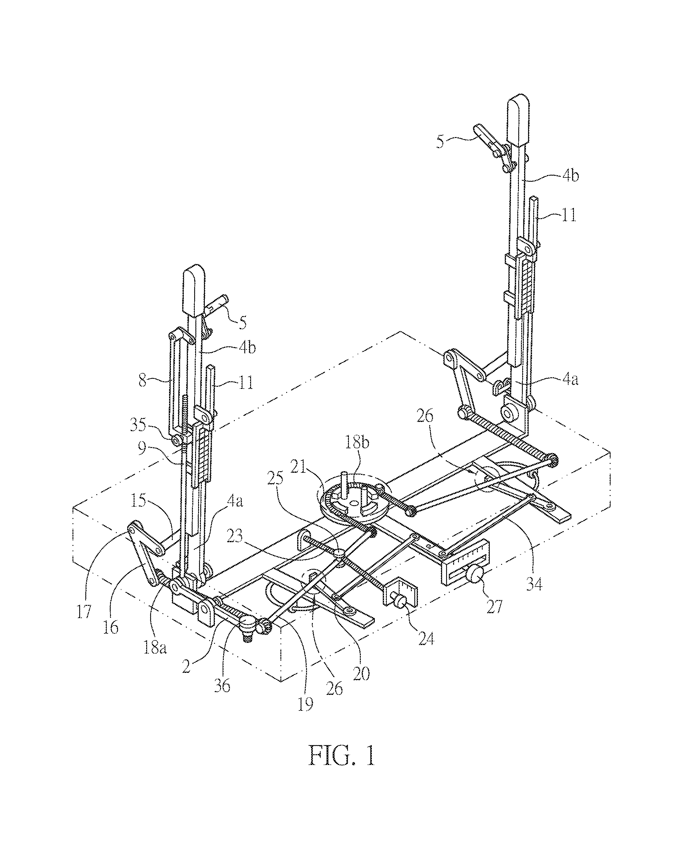
As shown in FIG. 1, the cited invention includes: a pair of rotatable frames which are rotatably inserted into a body 1; an oscillating linkage 2 which is shaft-supported in the body 1 and performs a seesaw operation; skipping handle parts 5 which are rotatably disposed at predetermined positions of the rotatable frames; a linkage mechanism which allows the oscillating linkage 2 to perform the seesaw operation by the rotation of the skipping handle parts 5; and a skipping foot plate 3 which is rotatably disposed on the upper portion of the body 1 and is rotated as one end of the oscillating linkage 2 hits the bottom surface thereof, and the cited invention enables users to perform skipping, rowing, and balancing simultaneously.
However, since the rotatable frames of the cited invention, which rotate forwards and backwards or rotate to the right and the left, have a long length, there are problems that the cited invention does not provide a sense of stability to users when they do the above-described exercises, and also, is not appropriate for users to perform a variety of different exercises to strengthen or maintain parts of their bodies they desire.
DETAILED DESCRIPTION OF THE PRESENT DISCLOSURE
Technical Objects
The present invention has been developed to solve the above-described problems, and an object of the present invention is to provide a multi-functional exercise apparatus which provides a sense of stability to a user when the user does an exercise, and simultaneously, allows the user to perform a variety of different exercises through a single apparatus.
Technical Solving Means
The present invention relates to a multi-functional exercise apparatus which provides a sense of stability to a user when the user does an exercise, and simultaneously, allows the user to perform a variety of different exercises through a single apparatus, the multi-functional exercise apparatus including: a plate-shaped body A which forms a bottom surface and has a space formed therein; fixed frames 100 which are fixedly disposed on both sides of the body A in an upward direction; rotatable frames which are disposed on both sides of the body A in an upward direction and provided so as to be rotatable; handle parts 200 which are connected with one side of the rotatable frames and provided so as to be rotatable forwards and backwards; and foot plate parts which are provided on a top surface of the body A and are connected with the other side of the rotatable frames and provided so as to be rotatable,
Effect of the Invention
In the multi-functional exercise apparatus according to the present invention, the rotatable frames include a plurality of links and interlock the handle parts and the foot plate parts. Therefore, the user can exercise by simply rotating only the handle parts relatively shorter than the rotatable frames, rather than by rotating the whole rotatable frames, and thus can feel a sense of stability.
In addition, since the links forming the rotatable frames are rotatably connected with the handle parts or the side surfaces of the fixed frames, the rotatable frames can stably transmit a driving force from the handle parts 200 to the foot plate parts, and also, can be changed so as to allow the user to perform a variety of different exercises.
BRIEF DESCRIPTION OF DRAWINGS
FIG. 1 is a perspective view showing a structure of a related-art multi-functional exercise apparatus;
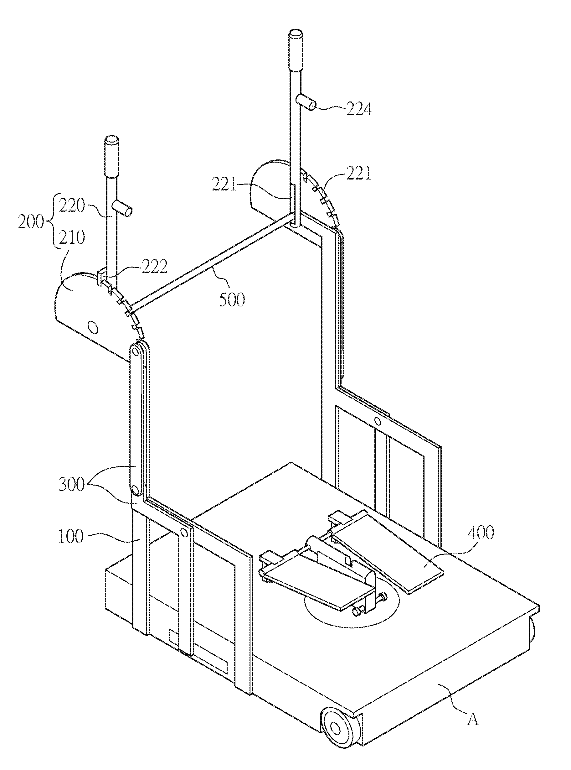
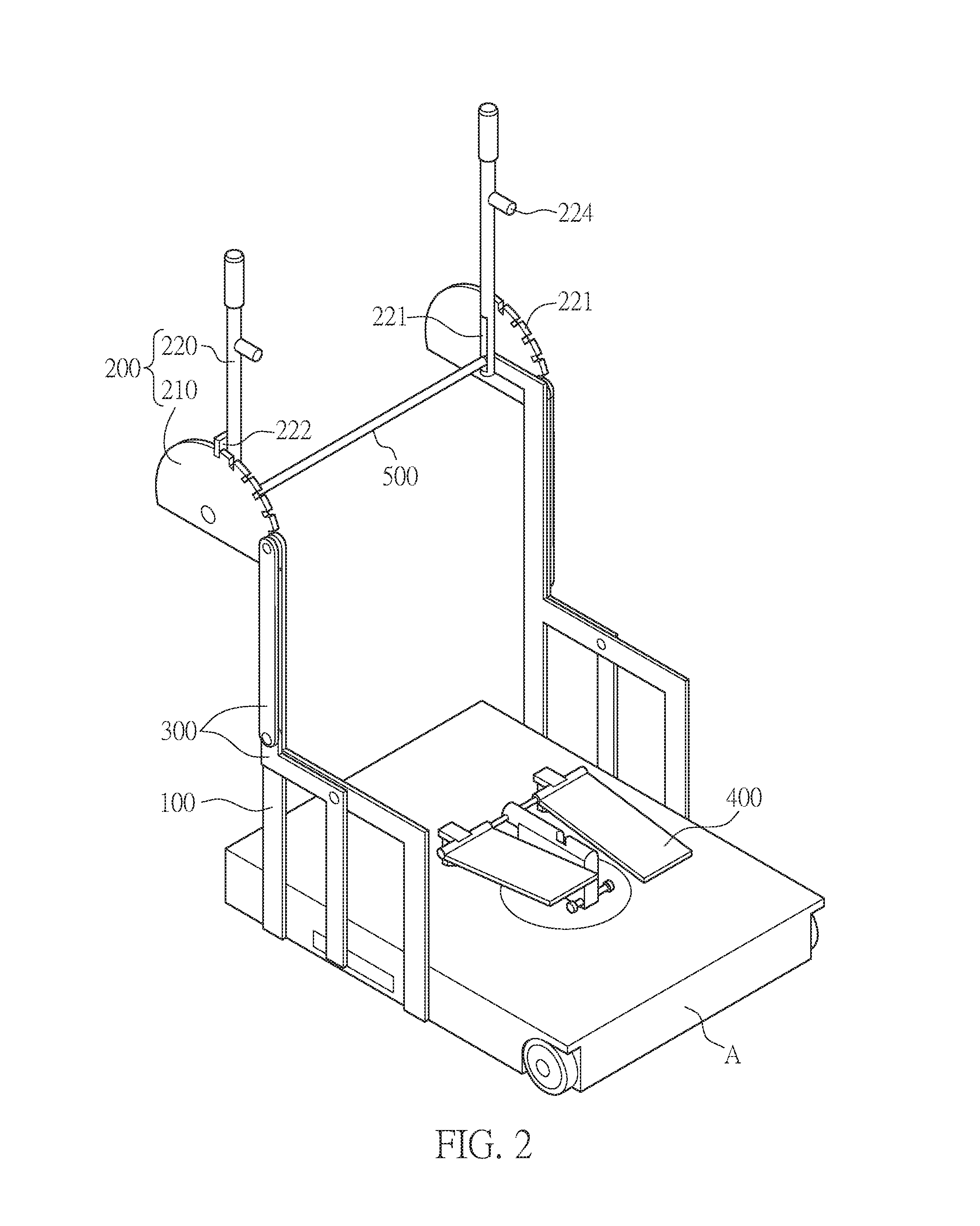
FIG. 2 is a perspective view showing the entirety of a multi-functional exercise apparatus of the present invention;
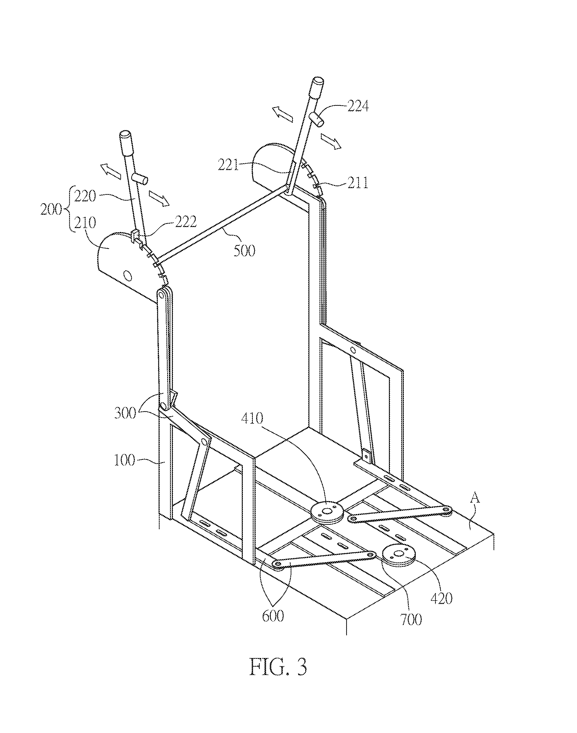
FIG. 3 is a perspective view showing an internal structure of the multi-functional exercise apparatus according to the present invention, and an example of driving thereof;
FIG. 4 is a perspective view showing an example of the interior of the multi-functional exercise apparatus of the present invention which is driven with a rope;
FIGS. 5a to 5c are views showing an example of a rotary plate and a main handle which are applied to the multi-functional exercise apparatus of the present invention, and are connected with and disconnected from each other;
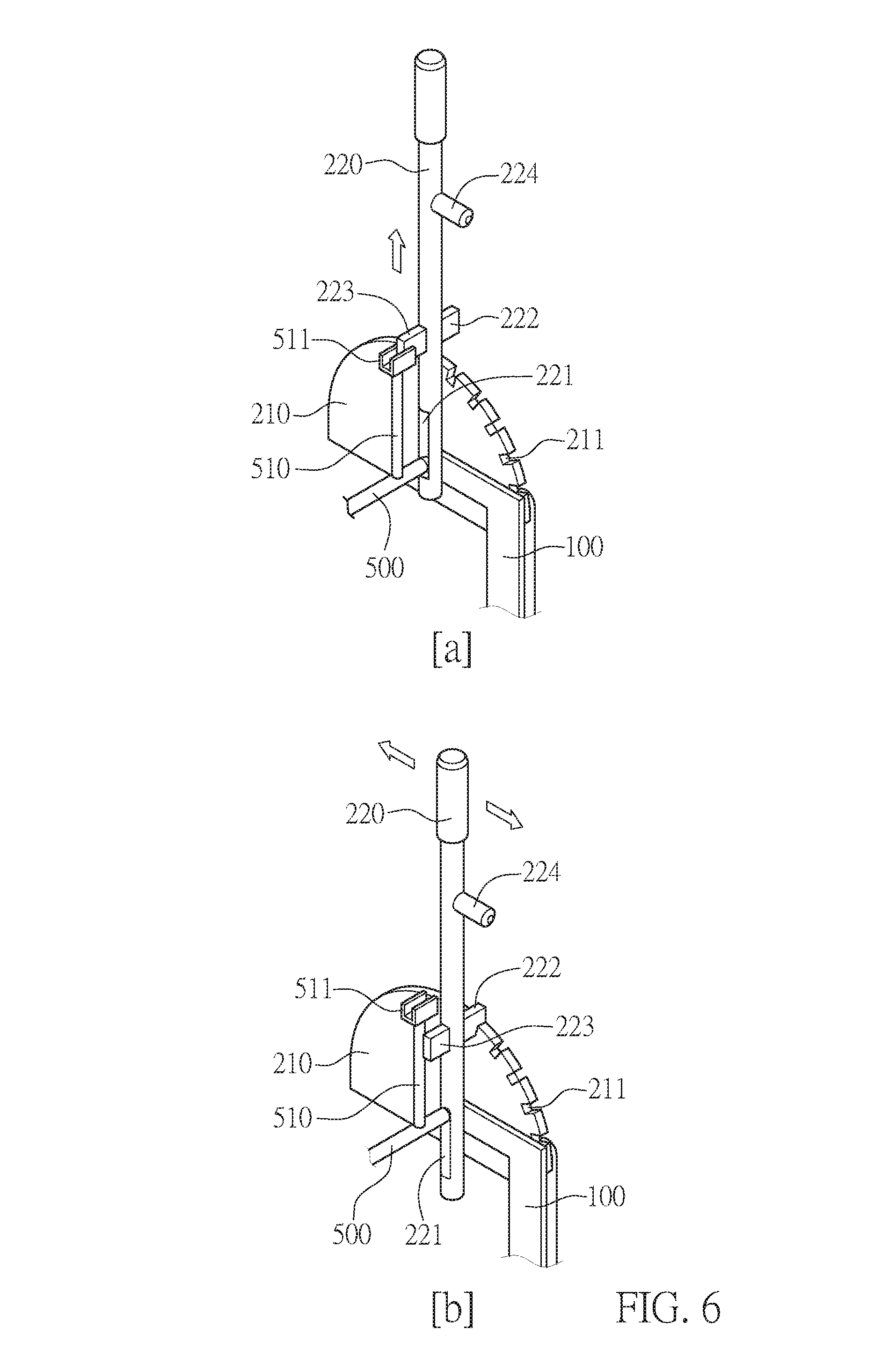
FIGS. 6a and 6b are views showing an example of the main handle and a seating mechanism which are applied to the multi-functional exercise apparatus of the present invention and are connected with and disconnected from each other;
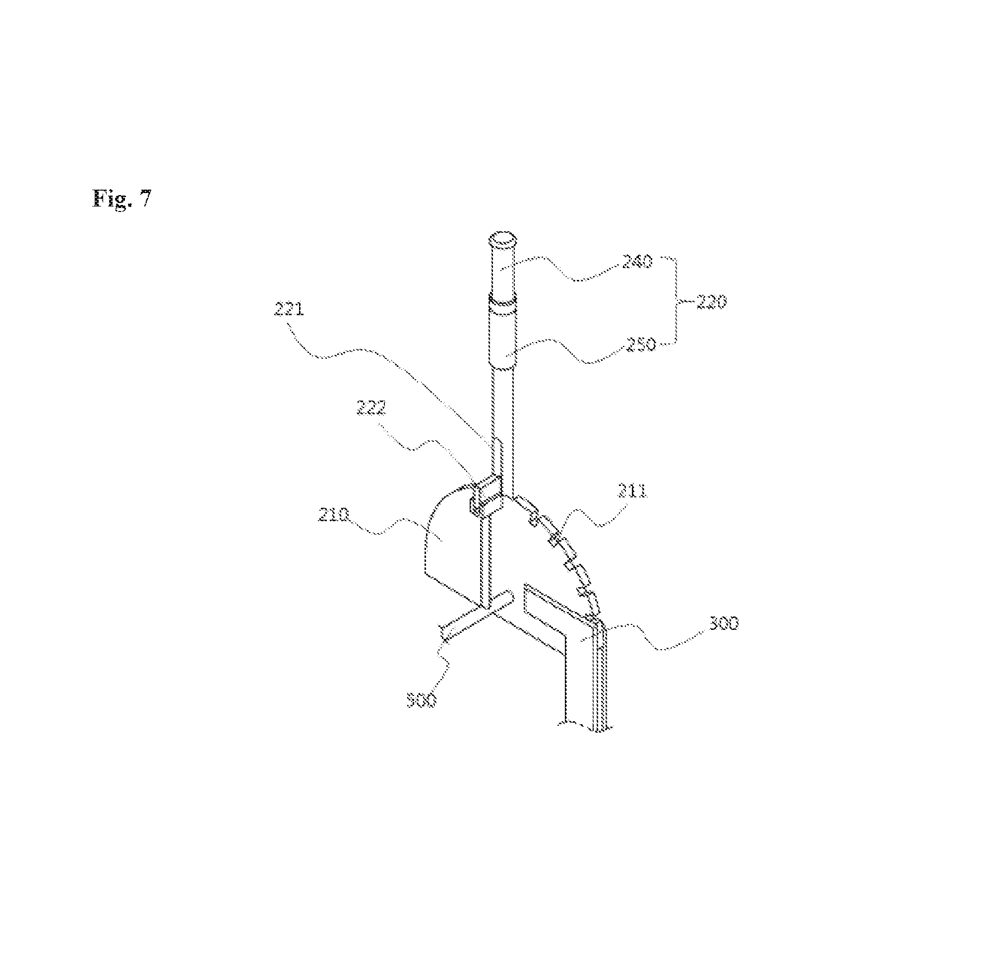
FIG. 7 is a perspective view showing another embodiment of the main handle applied to the multi-functional exercise apparatus of the present invention;
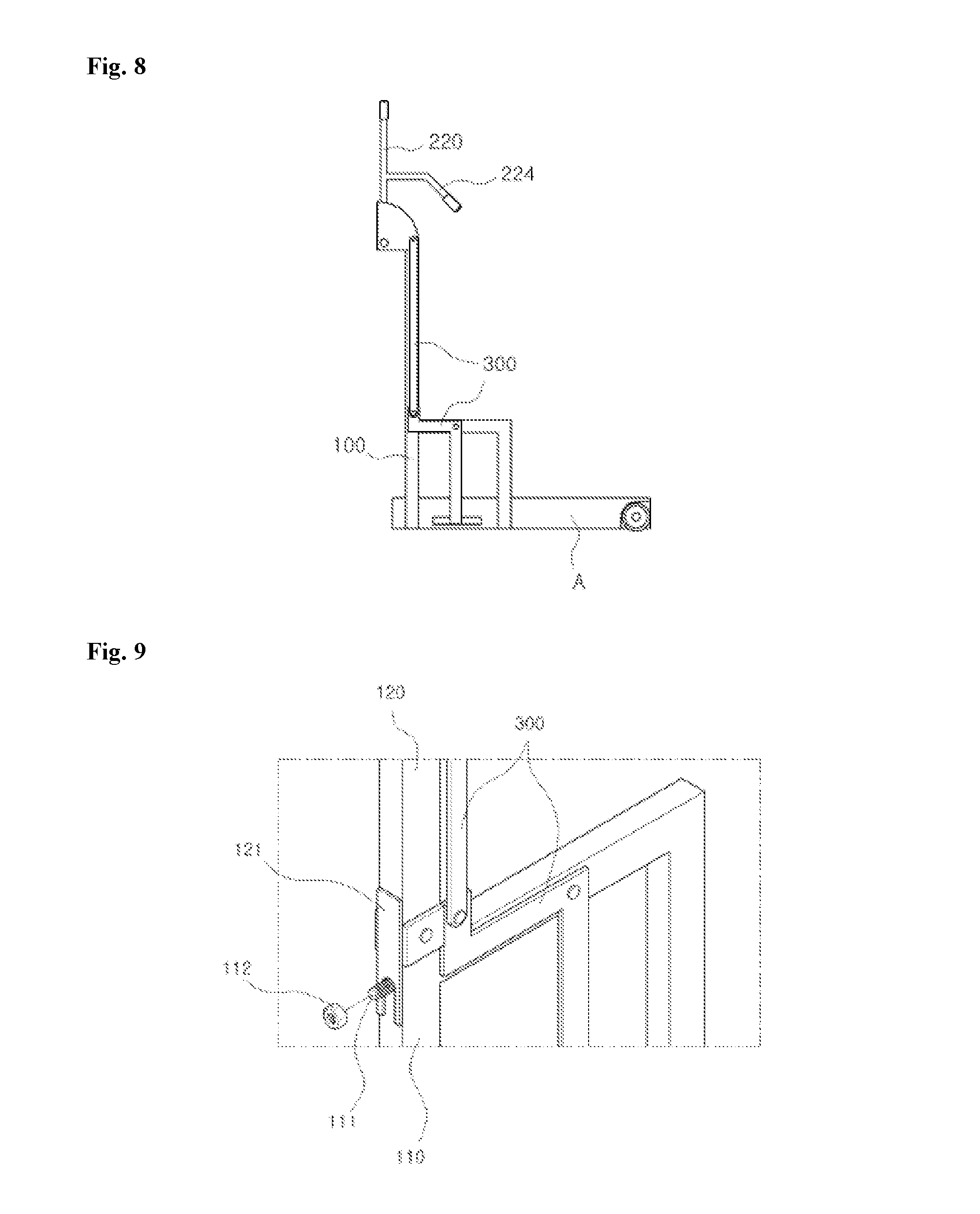
FIG. 8 is a perspective view showing structures of an upper fixed frame and a lower fixed frame applied to the multi-functional exercise apparatus of the present invention;
FIG. 9 is a perspective view showing a connection structure of the upper fixed frame and the lower fixed frame applied to the multi-functional exercise apparatus of the present invention;
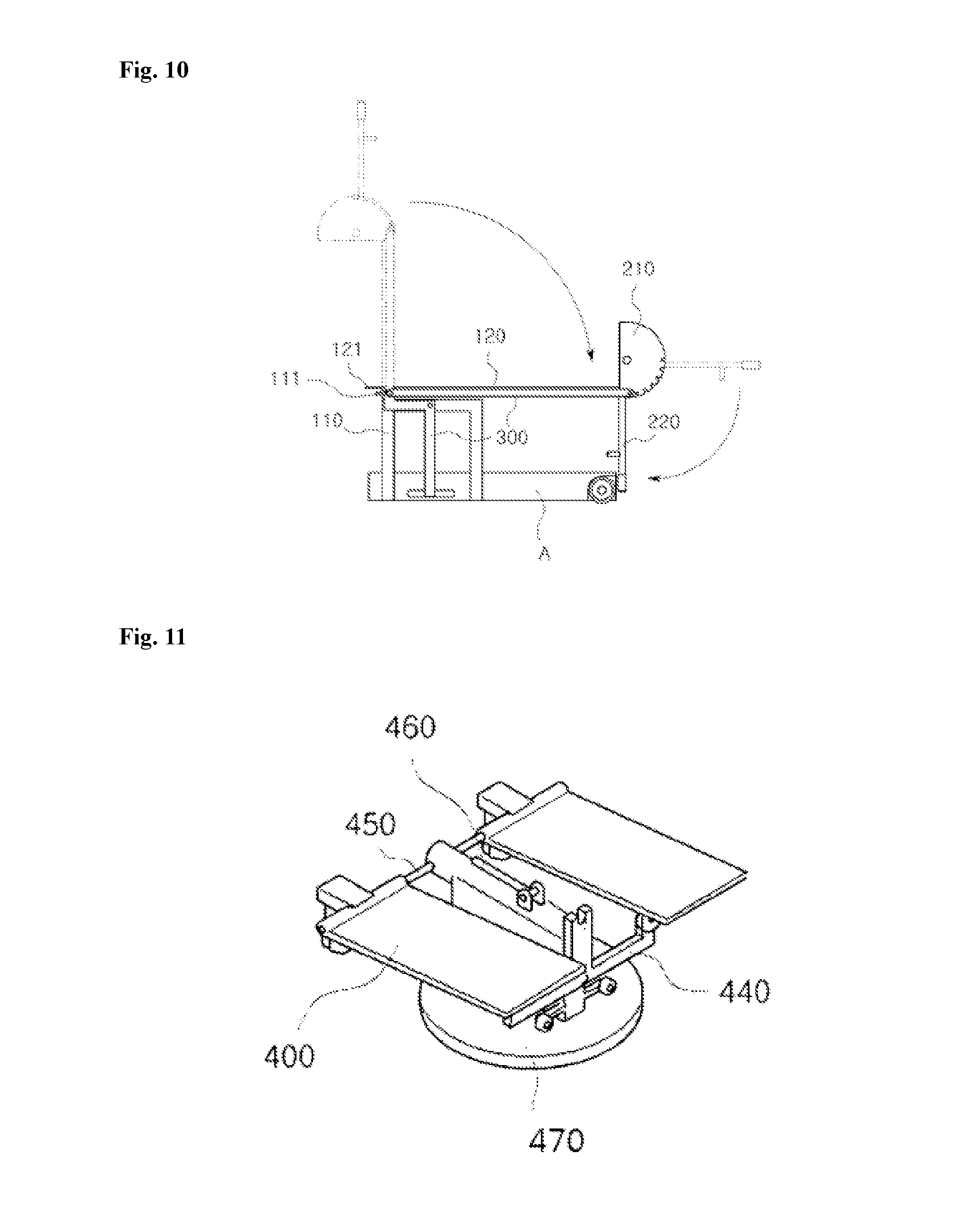
FIG. 10 is a view showing an example of the upper fixed frame which is applied to the multi-functional exercise apparatus of the present invention and is rotated;
FIG. 11 is a perspective view showing a structure of foot plate parts applied to the multi-functional exercise apparatus of the present invention;
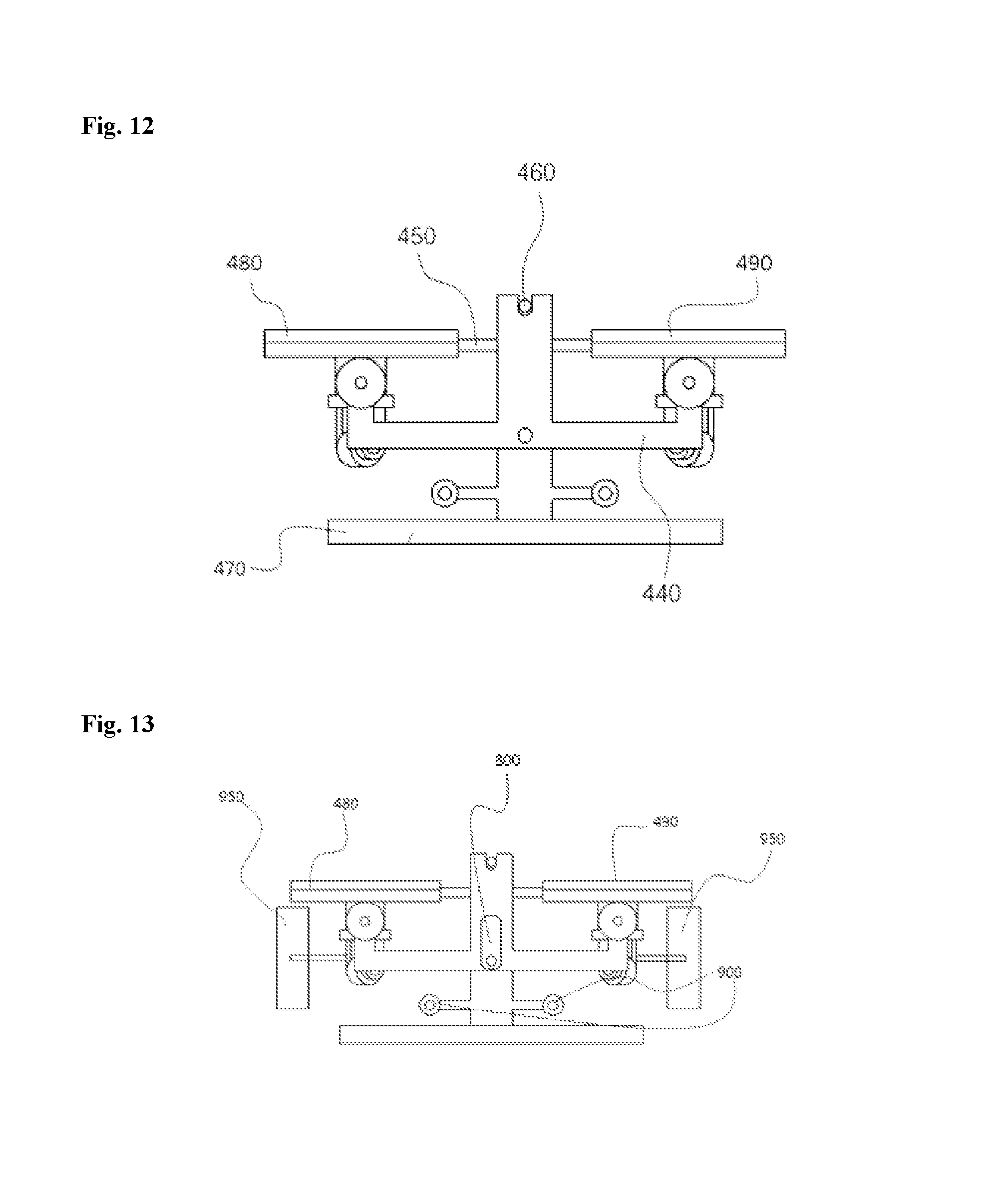
FIG. 12 is a rear view showing the structure of the foot plate parts applied to the multi-functional exercise apparatus of the present invention;
FIG. 13 is a rear view showing an example of rollers being applied to the foot plate parts applied to the multi-functional exercise apparatus of the present invention;
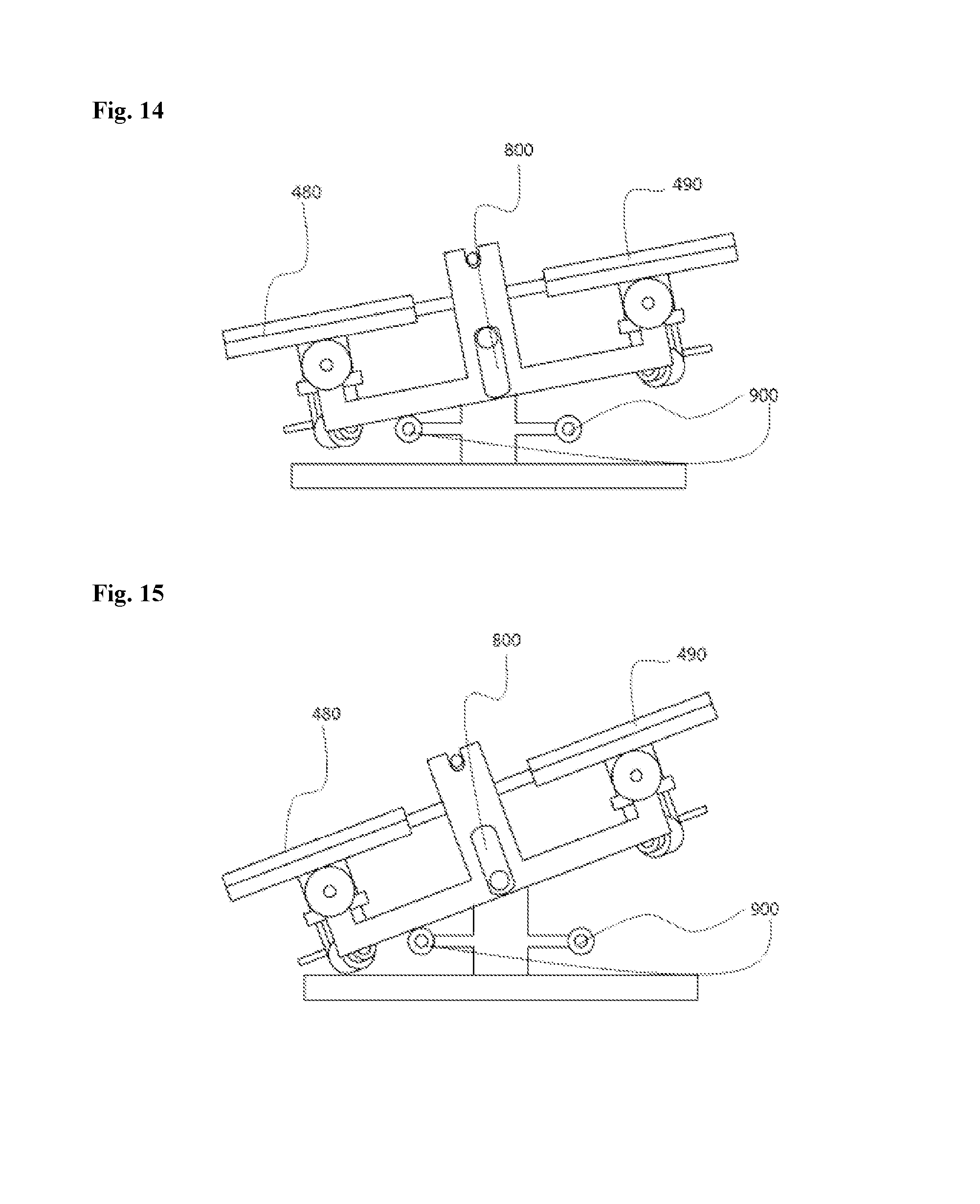
FIG. 14 is a rear view showing a moving pattern of the foot plate parts when a user does a step exercise on the foot plate parts applied to the multi-functional exercise apparatus of the present invention;
FIG. 15 is a rear view showing the foot plate parts which are stopped when the user gets on or off the foot plate parts applied to the multi-functional exercise apparatus of the present invention;
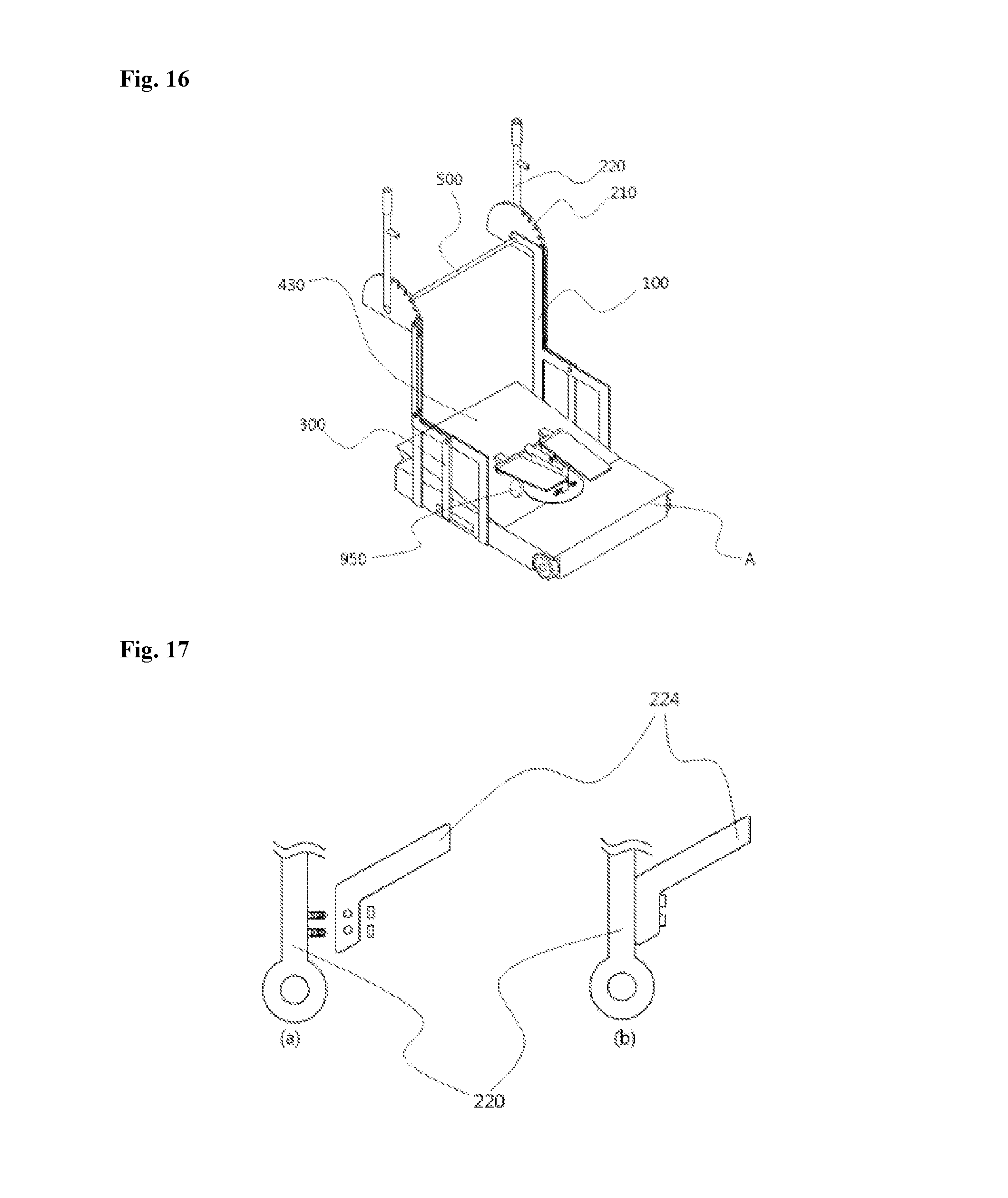
FIG. 16 is a perspective view showing the entirety of the multi-functional exercise apparatus of the present invention having a base plate elevated; and
FIG. 17 is a view showing an example of an auxiliary handle being connected with the main handle applied to the multi-functional exercise apparatus of the present invention; and
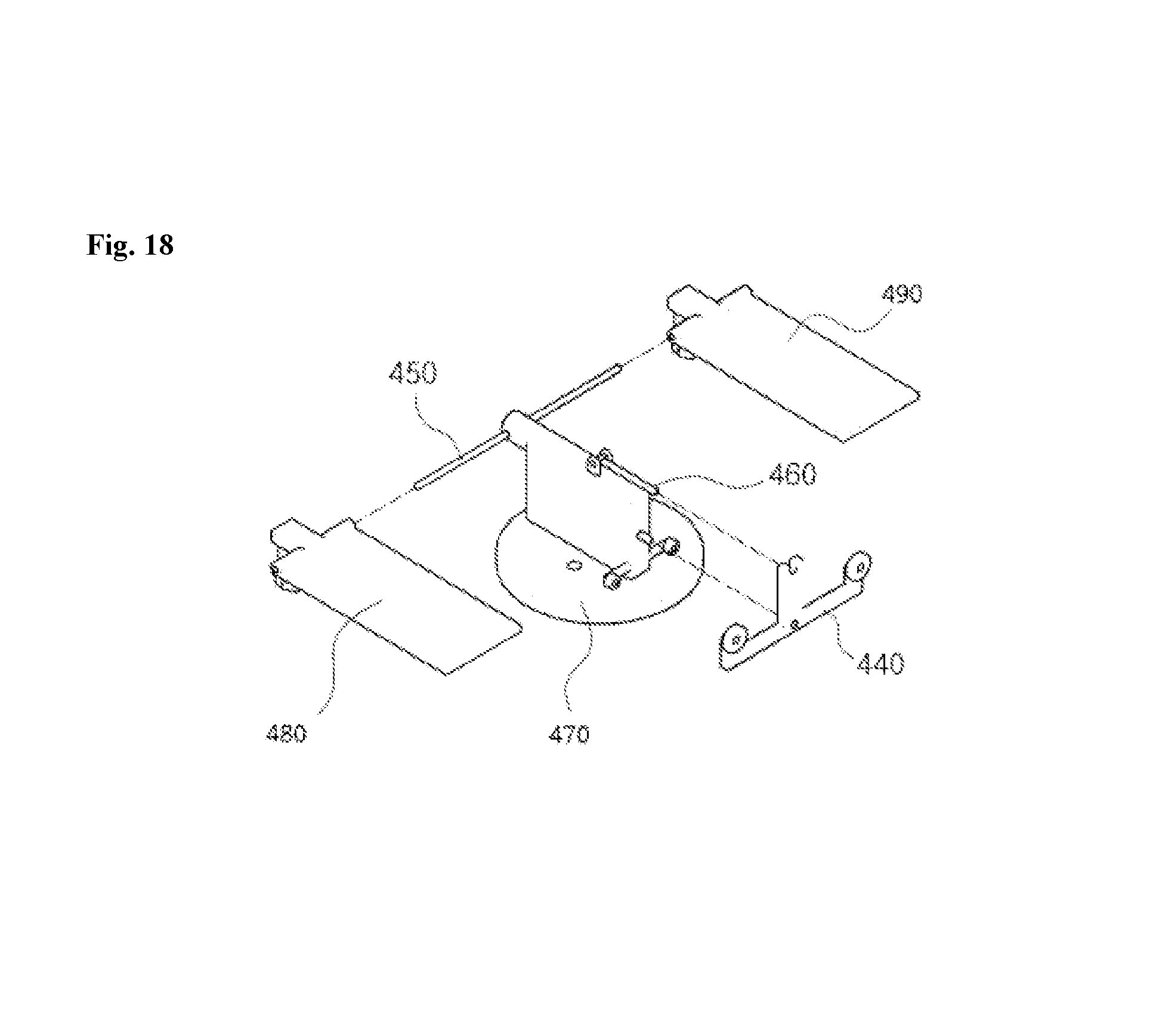
FIG. 18 is an exploded view showing a structure of foot plate parts applied to the multi-functional exercise apparatus of the present invention.
BEST MODE FOR EMBODYING THE INVENTION
Specific matters of the present invention including the object to be solved, the means for solving the object, and the effect of the present invention as described above are included in the embodiments and the drawings, which will be described below. The advantages and features of the present invention, and methods for achieving the same will be apparent with reference to the embodiments which will be described below with the accompanying drawings.
The present invention relates to a multi-functional exercise apparatus which provides a sense of stability to a user when the user does an exercise, and simultaneously, allows the user to perform a variety of different exercises through a single apparatus, and includes: a plate-shaped body A which forms a bottom surface and has a space formed therein; fixed frames 100 which are fixedly disposed on both sides of the body A in an upward direction; rotatable frames which are upwardly disposed on both sides of the body A and provided so as to be rotatable; handle parts 200 each of which is connected to one side of each of the rotatable frames and provided so as to be rotatable forwards and backwards; and foot plate parts which are provided on the top surface of the body A and each of which is connected to the other side of each of the rotatable frames and provided so as to be rotatable.
First, the body A is formed in a plate shape and supported on a bottom.
Specifically, as shown in FIGS. 2 to 4, the body A is a part forming the bottom surface of the multi-functional exercise apparatus according to the present invention, and allows a person to get thereon and to perform an exercise.
The body A may be provided with a plurality of wheels formed on the bottom surface so as to be easily moved, and has a space formed therein to accommodate therein a rope 700 connection structure and a link-joint structure for connecting the foot plate parts 400 and the rotatable frames 300.
In addition, the body may be provided with a base plate 430 formed on the front portion of the top surface thereof and configured to be able to adjust an incline to be elevated toward the user, such that the user can selectively adjust the incline.
Next, the fixed frames 100 are fixedly disposed on both side surfaces of the body A in the upward direction.
Specifically, the fixed frames 100 are formed in an "h"-shape as shown in FIGS. 2 to 4, and are fixedly disposed on both side surfaces of the body A in the upward direction, and the handle parts 200 are shaft-connected with the upper portions of the fixed frames 100 toward outside so as to be rotatable forwards and backwards.
More specifically, as shown in FIGS. 8 to 10, the fixed frames 100 may include lower fixed frames 110 which are fixedly disposed on the both side surfaces of the body A, and upper fixed frames 120, each of which has a lower end rotatably connected with the upper end of each of the lower fixed frames 110 and has an upper end connected with each of the handle parts 200 rotating forwards and backwards. The handle parts 200 and the upper fixed frames 120 are rotatable about the lower fixed frames 110 and thus are configured to be foldable, such that the multi-functional exercise apparatus can be easily stored.
An example of the upper fixed frames 120 being rotatably connected with the lower fixed frame 110 will be described in detail. As shown in FIG. 9, the lower fixed frame 110 may have a fixing protrusion 111 formed at a location spaced from the upper end thereof on the front surface thereof, and the upper fixed frame 120 may have an inserting mechanism 121 formed on the front surface thereof, having a predetermined length, and having a recess formed at a lower end thereof to receive the fixing protrusion 111. Herein, the fixed frame 100 may further include a fixing mechanism 112 secured to the fixing protrusion 111 and brought into contact with the inserting mechanism 121 when being secured to the fixing protrusion 111.
To do an exercise using the apparatus of the present invention, the user raises the upper fixed frames 120 which have been folded backwards by rotating the upper fixed frames 120 forwards, lets the fixing protrusion 111 be inserted into the inserting mechanism 121, and then secures the fixing mechanism 112 to the fixing protrusion 111. In addition, to store the apparatus of the present invention after using it, the user releases the fixing mechanism 112 from the fixing protrusion 111 and then rotates the upper fixed frames 120 backwards.
Next, the rotatable frames 300 are disposed upwardly on both sides of the body A and provided so as to be rotatable.
Specifically, the rotatable frames 300 are connected with the fixed frames 100 by means of links and joints and provided so as to be rotatable.
The links and joints forming the rotatable frames 300 may be formed in various shapes. For example, as shown in FIGS. 2 to 4, the links may include an "l"-shaped link and a ".right brkt-bot."-shaped link. The "l"-shaped link has one end rotatably connected with the handle part 200 and the other end rotatably connected with the ".right brkt-bot."-shaped link, and the ".right brkt-bot."-shaped link has one end connected with the "l"-shaped link and the other end connected with the rope 700 or the link-joint structure interlocked with the foot plate parts 400, which will be described below. In this case, the "l"-shaped link is rotatably shaft-connected with the handle part 200 and the ".right brkt-bot."-shaped link is rotatably shaft-connected with the side surface of the fixed frame 100, such that the rotatable frames 300 can stably transmit a driving force from the handle parts 200 to the foot plate parts 400.
The rotatable frames 300 include the plurality of links interlocked with one another, and the links are rotatably connected to the handle part 200 or the side surface of the fixed frame 100. Therefore, by simply moving only the handle parts 200 when exercising, the user can perform a rowing exercise using the handle parts 200 and a twist exercise using the foot plate parts 400 since the rotatable frames 300 move in association with the handle parts 200 and the foot plate parts 400 interlocked with the rotatable frames 300 rotate to the right and the left.
According to the present invention as described above, since the user performs an exercise by rotating only the handle parts 200, which are interlocked with the rotatable frames 300 and are relatively shorter than the rotatable frames 300, rather than doing a rowing exercise by moving the whole rotatable frames 300, a radius of rotation of the handle parts 200 is reduced and thus a sense of stability is provided to the user.
Next, the foot plate parts 400 are disposed on the upper portion of the body A and are interlocked with the rotatable frames 300 and provided so as to be rotatable to the right and the left.
Specifically, as shown in FIGS. 11 and 12, the foot plate parts 400 include a support plate 470, a left foot plate 480, and a right foot plate 490, and the support plate 470 forms a bottom surface in the foot plate parts 400.
The left foot plate 480 is provided on one side of the upper portion of the support plate 470 and configured to have a foot placed thereon.
The right foot plate 490 is provided on the other side of the upper portion of the support plate 470 and configured to have a foot placed thereon.
In this case, the left foot plate 480 and the right foot plate 490 are configured to be rotatable with the fore parts thereof having a fixed height, and the back parts thereof connected with each other in a seesaw form, such that a step exercise can be naturally performed when the foot plate parts 400 are rotated.
In addition, the left foot plate 480 and the right foot plate 490 may have protrusions formed on the back parts thereof as shown in FIG. 14, and, it is preferable that stopping protrusions 900 are further provided so as to prevent the lower portions of the left foot plate 480 and the right foot plate 490 from being brought into contact with the bottom when the user does a step exercise using the foot plate parts. This is to prevent the bottom surfaces of the left foot plate 480 and the right foot plate 490 from being damaged due to a friction on the bottom when the user does a step exercise on the foot plate parts.
In addition, when the user gets on or off the foot plate parts, the stopping protrusions 900 preventing the left foot plate 480 and the right foot plate 490 from being brought into contact with the bottom may put the user in danger. Therefore, as shown in FIG. 15, a stopping recess 800 may further be provided to allow a seesaw center shaft of the left foot plate 480 and the right foot plate 490 to rise and descend so as to bring the lower portion into contact with the bottom when the user places a foot on only one of the left foot plate 480 and the right foot plate 490 to get on or off the foot plate parts. Accordingly, when a force is applied only to the one foot plate, the seesaw center shaft of the left foot plate 480 and the right foot plate 490 rise due to the presence of the stopping recess 800 and the lower portion of the left foot plate 480 or the right foot plate 490 is brought into contact with the bottom surface.
In addition, rollers 950 may further be provided under the left foot plate 480 and the right foot plate 490 as shown in FIG. 13. In the state in which the incline of the base plate 430 increases as shown in FIG. 16, this is to allow the user to do a step exercise in such a manner that the roller 950 of the left foot plate 430 naturally moves up along the inclined surface of the base plate 430 when the foot plate parts rotate to the right, and to allow the user to a step exercise in such a manner that the roller 950 of the right foot plate 490 naturally moves up along the inclined surface of the support plate 430 when the foot plate parts rotate to the left.
The foot plate parts 400 are connected to a rotary circular plate 410 disposed at the center of the body A, and are rotated to the right and the left as the rotary circular plate 410 rotates to the right and the left. In this case, the rotary circular plate 410 is connected with the rotatable frames 300 and inner operating frames 600 by means of the rope 700 or links and joints.
For example, as shown in FIG. 4, the inner operating frames 600 are formed in a bar shape, and have joints formed at one side and the other side thereof and are connected with the rope 700 or connected in the form of links and joints and rotated.
Due to the forward and backward rotation of the handle parts 200, the rotatable frames rotate forwards and backwards. Due to the rotation of the rotatable frames, the rotary circular plate connected with the rotatable frames via the rope 700 and the link and joints rotate to the right and the left, such that the foot plate parts can rotate to the right and the left.
Specifically, the user should alternately move the handle parts 200 provided at the both sides of the body A to perform a rowing exercise while alternately stretching and contracting both arms. In this case, the inner operating frames 600 which are connected with the rotatable frames 300 symmetrically formed are disposed to have the same inclination with reference to a certain point of the rope 700 and to alternate as shown in FIG. 3. Accordingly, when the user pushes one handle part 200 forwards and pulls the other handle part 200 backward, the foot plate parts 400 connected with the rotary circular plate 410 are rotated in one direction of the leftward direction and the rightward direction, and, when the user operates the handle parts 200 in reverse, the foot plate parts 400 are rotated in the other direction.
Next, the handle parts 200 are connected with the rotatable frames 300 and provided as to be rotatable forwards and backwards.
Specifically, as shown in FIGS. 5 and 6, the handle part 200 is provided with a rotary plate 210 which has a plurality of locking recesses 211 formed along the circumference thereof, has a center shaft-connected with the outer surface of the upper portion of the fixed frame 100 to rotate forwards and backwards, and has a side surface connected with the link of the rotatable frame 300, spaced from the center, so as to be interlocked with the link of the rotatable frame 300.
In addition, the handle part 200 may be provided with a main handle 220 having a predetermined length and connected with the outside of the rotary plate 210, and having a locking protrusion 222 formed on one side thereof to be inserted into the locking recess 211, and may further be provided with an auxiliary handle 224 attachably and detachably formed on one side of the center of the main handle 220.
In this case, by inserting the locking protrusion 222 into the locking recess 211, the angle of the main handle 220 may be adjusted.
According to another embodiment, as shown in FIG. 7, the main handle 220 may include a handle piston 240 of a bar type having the locking protrusion 222 formed at a lower portion thereof, and a handle cylinder 250 formed in a bar shape and having a cavity formed therein to accommodate the lower portion of the handle piston 240, and having a protrusion recess 221 formed in a lengthwise direction so as to allow the locking protrusion 222 to protrude to the outside and move up and down.
Due to the configuration of the main handle 220 according to another embodiment, the angle of the handle part can be easily adjusted and a better sense of stability can be provided to the user when the handle part is rotated. More specifically, the position of the handle part is adjusted while lifting the handle piston 240, and then, by releasing the handle piston 240, the locking protrusion 222 is locked into the locking recess 211 of the rotary plate 210, such that the handle part 200 is positioned at a right position to be used by the user. To achieve this, a spring is provided inside the handle cylinder 250 to allow the handle piston 240 to have a downward elastic force. Therefore, when the user pulls the handle piston 240 to the outside and releases the handle piston 240 at a desired position, the handle piston 240 is inserted again due to the presence of the spring and the locking protrusion 222 is inserted into the locking recess 211.
By inserting the locking protrusion 222 into one of the plurality of locking recesses 211 described above, the user may select a range/angle of movements of user's both arms when doing a rowing exercise. For example, when the plurality of locking recesses 211 are formed on the rotary plate 210 as shown in FIG. 5a, the user may perform a rowing exercise forwards and backwards by inserting the locking protrusion 222 into the locking recess 211 formed at the uppermost end, and may perform a rowing exercise upwardly and downwardly by inserting the locking protrusion 222 into the locking recess 211 formed at the lowermost end. Accordingly, the user may perform exercises using different muscles by adjusting the position of the main handle 220.
The auxiliary handle 224 may be configured to be attachable and detachable when necessary as shown in FIG. 17.
As shown in FIGS. 2 and 3, the multi-functional exercise apparatus may further include a horizontal frame 500 connecting the upper ends of the fixed frames 100 disposed on both side surfaces of the body A. The horizontal frame 500 serves as a handle when the user uses only the foot plate parts 400. In addition, as shown in FIG. 5a, the horizontal frame 500 may have a seating mechanism 510 protruding to be adjacent to the main handle 220, and the locking protrusion 222 inwardly formed on the main handle 220 may be inserted into the seating mechanism 510.
When the locking protrusion 222 is inserted into a seating recess 511, the main handle 220 is fixed and only the rotatable frames 300 and the rotary plate 210 interlocked with the foot plate parts 400 are driven according to the rightward and leftward rotation of the foot plate parts 400. Accordingly, the user can perform a twist exercise and a step exercise using only the foot plate parts 400.
As described above, the foot plate parts 400 are connected with the rotary circular plate 410 through the support plate 470 as shown in FIG. 11. The support plate 470 has a center portion protruding from the top surface thereof and thus a cross section formed in the shape of "", and the two foot plate parts 400 are symmetrically connected with each other with reference to the support plate 470 through the protruding part, such that the user can perform the step exercise in addition to the twist exercise through the foot plate parts 400.
More specifically, a shaft pin 450 is formed on the front surface of the protruding part to be shaft-connected with the front surfaces of the two foot plate parts 400, and a support frame 440 is shaft-connected with the rear surface of the protruding part, such that the support frame 440 is rotated according to pressure applied to the foot plate parts 400 and thus the user can perform the step exercise.
In addition, as shown in FIG. 18, a fixing pin 460 may be formed on the top surface of the protruding part so as to protrude backwardly during rotation, and the support frame 440 is formed in the shape of "" and may have a recess formed on the center protruding therefrom to receive the fixing pin 460. When the fixing pin 460 is received in the recess formed on the support frame 440, the user is not allowed to perform the step exercise and is allowed to perform only the twist exercise using the foot plate parts 400.
In addition, as mentioned above, when the user performs the twist exercise on the foot plate parts 400 through the base plate 430 having a high incline toward the front surface, the user can naturally perform the step exercise in parallel with the twist exercise due to the inclined surface of the base plate 430.
It would be understood by a person skilled in the art that the present invention can be embodied in other specific forms without changing the technical idea or essential features of the present invention.
Therefore, the above-described embodiments should be understood as being exemplary and should not be considered as limiting from all aspects of the invention. The scope of the invention is defined not by the detailed description of the invention but by the appended claims, and all changes or changed forms derived from the meaning and range of the appended claims and equivalents thereof should be interpreted as being included in the scope of the present invention.
SEQUENCE LIST FREE TEXT
A: body 100: fixed frame 110: lower fixed frame 111: fixing protrusion 112: fixing mechanism 120: upper fixed frame 121: inserting mechanism 200: handle part 210: rotary plate 211: locking recess 220: main handle 222: locking protrusion 224: auxiliary handle 240: handle piston 250: handle cylinder 221: protrusion recess 300: rotatable frame 400: foot plate part 410: rotary circular plate 420: auxiliary circuit plate 430: base plate 440: support frame 450: shaft pin 460: fixing pin 470: support plate 480: left foot plate 490: right foot plate 500: horizontal frame 510: seating mechanism 511: seating recess 600: inner operating frame 700: rope 800: stopping recess 900: stopping protrusion 950; roller
* * * * *
D00000
D00001
D00002
D00003
D00004
D00005
D00006
D00007
D00008
D00009
D00010
D00011
D00012
D00013
P00001

XML
uspto.report is an independent third-party trademark research tool that is not affiliated, endorsed, or sponsored by the United States Patent and Trademark Office (USPTO) or any other governmental organization. The information provided by uspto.report is based on publicly available data at the time of writing and is intended for informational purposes only.
While we strive to provide accurate and up-to-date information, we do not guarantee the accuracy, completeness, reliability, or suitability of the information displayed on this site. The use of this site is at your own risk. Any reliance you place on such information is therefore strictly at your own risk.
All official trademark data, including owner information, should be verified by visiting the official USPTO website at www.uspto.gov. This site is not intended to replace professional legal advice and should not be used as a substitute for consulting with a legal professional who is knowledgeable about trademark law.