Patient interface systems
Kooij , et al.
U.S. patent number 10,245,404 [Application Number 14/810,525] was granted by the patent office on 2019-04-02 for patient interface systems. This patent grant is currently assigned to ResMed Limited. The grantee listed for this patent is ResMed Limited. Invention is credited to Adam Francis Barlow, Achim Biener, Aaron Samuel Davidson, Renee Frances Flower, Justin John Formica, Joel Edward Gibson, Dieter Heidmann, Scott Alexander Howard, Michiel Kooij, Bernd Christoph Lang, Damien Julian Mazzone, Michael John Reid, Gerard Michael Rummery.


View All Diagrams
| United States Patent | 10,245,404 |
| Kooij , et al. | April 2, 2019 |
Patient interface systems
Abstract
A patient interface system for delivering a flow of breathable gas to a patient includes a patient interface structure configured to sealingly engage the face of the patient and a retaining element configured for application to the patient. The retaining element is configured to support the patient interface structure in sealing engagement with the face of the patient. The retaining element includes an adhesive and/or at least one strap. In addition, the patient interface structure is configured to be released from and re-engaged with the retaining element for re-positioning of the patient interface structure relative to the patient's face in a plurality of positions while the retaining element remains supported by the patient.
| Inventors: | Kooij; Michiel (Sydney, AU), Howard; Scott Alexander (Sydney, AU), Formica; Justin John (Sydney, AU), Rummery; Gerard Michael (Woodford, AU), Flower; Renee Frances (Sydney, AU), Barlow; Adam Francis (Sydney, AU), Gibson; Joel Edward (Sydney, AU), Mazzone; Damien Julian (Sydney, AU), Davidson; Aaron Samuel (Sydney, AU), Lang; Bernd Christoph (Graefelfing, DE), Biener; Achim (Aufkirchen, DE), Reid; Michael John (Sydney, AU), Heidmann; Dieter (Geretsried, DE) | ||||||||||
|---|---|---|---|---|---|---|---|---|---|---|---|
| Applicant: |
|
||||||||||
| Assignee: | ResMed Limited (Bella Vista,
AU) |
||||||||||
| Family ID: | 40957743 | ||||||||||
| Appl. No.: | 14/810,525 | ||||||||||
| Filed: | July 28, 2015 |
Prior Publication Data
| Document Identifier | Publication Date | |
|---|---|---|
| US 20150328425 A1 | Nov 19, 2015 | |
Related U.S. Patent Documents
| Application Number | Filing Date | Patent Number | Issue Date | ||
|---|---|---|---|---|---|
| 13619512 | Sep 14, 2012 | 9149594 | |||
| 12478537 | Oct 23, 2012 | 8291906 | |||
| 61058659 | Jun 4, 2008 | ||||
| 61080847 | Jul 15, 2008 | ||||
| Current U.S. Class: | 1/1 |
| Current CPC Class: | A61M 16/0616 (20140204); A61M 16/0611 (20140204); A61M 16/0683 (20130101); A61M 16/0666 (20130101); A61M 16/0688 (20140204); A61M 16/0633 (20140204); A61M 16/0875 (20130101); A61M 16/0825 (20140204) |
| Current International Class: | A61M 16/06 (20060101); A61M 16/08 (20060101) |
| Field of Search: | ;128/206.14,206.25,207.11,207.17 |
References Cited [Referenced By]
U.S. Patent Documents
| 443191 | December 1890 | Illing |
| 781516 | January 1905 | Guthrie, Jr. |
| 1081745 | December 1913 | Johnston |
| 1125542 | January 1915 | Humphries |
| 1192186 | July 1916 | Greene |
| 1229050 | June 1917 | Donald |
| 1282527 | October 1918 | Bidonde |
| 1362766 | December 1920 | McGargill |
| 1445010 | February 1923 | Feinberg |
| 1610793 | December 1926 | Kaufman |
| 1873160 | August 1932 | Sturtevant |
| 2353643 | July 1944 | Bulbulian |
| 2415846 | February 1947 | Randall |
| 2433565 | December 1947 | Korman |
| 2625155 | January 1953 | Engelder |
| 2706983 | April 1955 | Matheson et al. |
| 2931356 | April 1960 | Schwarz |
| 3013556 | December 1961 | Galleher |
| 3357426 | December 1967 | Cohen |
| 3670726 | March 1972 | Mahon et al. |
| 3682171 | August 1972 | Dali et al. |
| 3739774 | June 1973 | Gregory |
| 3754552 | August 1973 | King |
| 3861385 | January 1975 | Carden |
| 3902486 | September 1975 | Guichard |
| 3905361 | September 1975 | Hewson et al. |
| 3938614 | February 1976 | Ahs |
| 3972321 | August 1976 | Proctor |
| 4006744 | February 1977 | Steer |
| 4142527 | March 1979 | Garcia |
| 4153051 | May 1979 | Shippert |
| 4156426 | May 1979 | Gold |
| 4248218 | February 1981 | Fischer |
| 4263908 | April 1981 | Mizerak |
| 4264743 | April 1981 | Maruyama et al. |
| 4267845 | May 1981 | Robertson, Jr. et al. |
| 4273124 | June 1981 | Zimmerman |
| 4312359 | January 1982 | Olson |
| 4367735 | January 1983 | Dali |
| 4367816 | January 1983 | Wilkes |
| 4406283 | September 1983 | Bir |
| 4414973 | November 1983 | Matheson et al. |
| 4422456 | December 1983 | Teip |
| 4449526 | May 1984 | Elam |
| 4455675 | June 1984 | Bose et al. |
| 4493614 | January 1985 | Chu et al. |
| 4548200 | October 1985 | Wapner |
| 4549542 | November 1985 | Chein |
| 4572323 | February 1986 | Randall |
| 4587967 | May 1986 | Chu et al. |
| 4601465 | July 1986 | Roy |
| 4617637 | November 1986 | Chu et al. |
| 4630604 | December 1986 | Montesi |
| 4641647 | February 1987 | Behan |
| 4648398 | March 1987 | Agdanowski et al. |
| 4660555 | April 1987 | Payton |
| 4665566 | May 1987 | Garrow |
| 4671271 | June 1987 | Bishop et al. |
| 4676241 | June 1987 | Webb et al. |
| 4699139 | October 1987 | Marshall et al. |
| 4706664 | November 1987 | Snook et al. |
| 4711636 | December 1987 | Bierman |
| 4713844 | December 1987 | Westgate |
| D293613 | January 1988 | Wingler |
| 4753233 | June 1988 | Grimes |
| 4767411 | August 1988 | Edmunds |
| 4774946 | November 1988 | Ackerman et al. |
| 4782832 | November 1988 | Trimble et al. |
| 4790829 | December 1988 | Bowden et al. |
| 4802857 | February 1989 | Laughlin |
| 4803981 | February 1989 | Vickery |
| 4811730 | March 1989 | Milano |
| 4830138 | May 1989 | Palmaer et al. |
| 4838878 | June 1989 | Kalt et al. |
| 4899740 | February 1990 | Napolitano |
| 4907584 | March 1990 | McGinnis |
| 4915105 | April 1990 | Lee |
| 4919128 | April 1990 | Kopala et al. |
| 4919654 | April 1990 | Kalt |
| 4944310 | July 1990 | Sullivan |
| 4945907 | August 1990 | Tayebi |
| 4960121 | October 1990 | Nelson et al. |
| 4966590 | October 1990 | Kalt |
| 4969880 | November 1990 | Zamierowski |
| 4971051 | November 1990 | Toffolon |
| 4976698 | December 1990 | Stokley |
| 4989599 | February 1991 | Carter |
| 4996983 | March 1991 | Amrhein |
| 5000173 | March 1991 | Zalkin et al. |
| 5005571 | April 1991 | Dietz |
| 5020163 | June 1991 | Aileo et al. |
| 5022900 | June 1991 | Bar-Yona et al. |
| 5023955 | June 1991 | Murphy, II et al. |
| 5025805 | June 1991 | Nutter |
| 5038772 | August 1991 | Kolbe et al. |
| 5042478 | August 1991 | Kopala et al. |
| 5046491 | September 1991 | Derrick |
| 5074297 | December 1991 | Venegas |
| 5113857 | May 1992 | Dickerman et al. |
| 5117818 | June 1992 | Palfy |
| 5121745 | June 1992 | Israel |
| 5127397 | July 1992 | Kohnke |
| 5137017 | August 1992 | Salter |
| 5138722 | August 1992 | Urella et al. |
| D333015 | February 1993 | Farmer et al. |
| 5188101 | February 1993 | Tumolo |
| 5207665 | May 1993 | Davis et al. |
| 5220699 | June 1993 | Farris |
| 5243709 | September 1993 | Sheehan et al. |
| 5243971 | September 1993 | Sullivan et al. |
| 5245995 | September 1993 | Sullivan et al. |
| 5261893 | November 1993 | Zamierowski |
| 5263939 | November 1993 | Wortrich |
| 5265592 | November 1993 | Beaussant |
| 5265595 | November 1993 | Rudolph |
| 5267557 | December 1993 | Her-Mou |
| 5269296 | December 1993 | Landis |
| 5271391 | December 1993 | Graves |
| 5304146 | April 1994 | Johnson et al. |
| 5299599 | May 1994 | Farmer et al. |
| 5320092 | June 1994 | Ryder |
| 5335656 | August 1994 | Bowe et al. |
| 5349949 | September 1994 | Schegerin |
| 5355878 | October 1994 | Griffiths et al. |
| 5355893 | October 1994 | Mick et al. |
| 5364367 | November 1994 | Banks et al. |
| 5372130 | December 1994 | Stem et al. |
| 5372388 | December 1994 | Gargiulo |
| 5372389 | December 1994 | Tam et al. |
| 5372390 | December 1994 | Conway et al. |
| 5372391 | December 1994 | Bast et al. |
| 5375593 | December 1994 | Press |
| 5385141 | January 1995 | Granatiero |
| 5394568 | March 1995 | Brostrom et al. |
| 5396885 | March 1995 | Nelson |
| 5398676 | March 1995 | Press et al. |
| 5400776 | March 1995 | Bartholomew |
| 5419318 | May 1995 | Tayebi |
| 5425359 | June 1995 | Liou |
| 5429683 | July 1995 | Le Mitouard |
| 5437267 | August 1995 | Weinstein et al. |
| 5441046 | August 1995 | Starr et al. |
| 5462528 | October 1995 | Roewer |
| 5477852 | December 1995 | Landis et al. |
| 5488948 | February 1996 | Dubruille et al. |
| 5509409 | April 1996 | Weatherholt |
| 5513634 | May 1996 | Jackson |
| 5513635 | May 1996 | Bedi |
| 5526806 | June 1996 | Sansoni |
| 5533506 | July 1996 | Wood |
| 5538000 | July 1996 | Rudolph |
| 5538001 | July 1996 | Bridges |
| 5560354 | October 1996 | Berthon-Jones et al. |
| 5570684 | November 1996 | Behr |
| 5592938 | January 1997 | Scarberry et al. |
| 5623923 | April 1997 | Bertheau et al. |
| 5647357 | July 1997 | Barnett et al. |
| 5653224 | August 1997 | Johnson |
| 5653228 | August 1997 | Byrd |
| 5655527 | August 1997 | Scarberry et al. |
| 5662101 | September 1997 | Ogden et al. |
| 5669377 | September 1997 | Fenn |
| 5682881 | November 1997 | Winthrop et al. |
| 5704345 | January 1998 | Berthon-Jones et al. |
| 5704916 | January 1998 | Byrd |
| 5707342 | January 1998 | Tanaka |
| 5724965 | March 1998 | Handke et al. |
| 5727544 | March 1998 | Miura |
| 5735272 | April 1998 | Dillon |
| 5740799 | April 1998 | Nielson |
| 5752511 | May 1998 | Simmons et al. |
| 5794619 | August 1998 | Edeiman et al. |
| 5803066 | September 1998 | Rapoport |
| 5807341 | September 1998 | Heim |
| 5842469 | December 1998 | Rapp et al. |
| 5906203 | May 1999 | Klockseth et al. |
| 5918598 | July 1999 | Belfer et al. |
| 5921239 | July 1999 | McCall et al. |
| 5931854 | August 1999 | Dillon |
| 5954049 | September 1999 | Foley et al. |
| 5975079 | November 1999 | Hellings et al. |
| 5976173 | November 1999 | Berke |
| 6019101 | January 2000 | Cotner et al. |
| 6026811 | February 2000 | Settle |
| 6044844 | April 2000 | Kwok et al. |
| 6050260 | April 2000 | Daniell et al. |
| 6082360 | July 2000 | Rudolph et al. |
| 6086118 | July 2000 | McNaughton et al. |
| 6093169 | July 2000 | Cardoso |
| 6095996 | August 2000 | Steer et al. |
| 6098205 | August 2000 | Schwartz et al. |
| 6109263 | August 2000 | Feuchtgruber |
| 6112746 | September 2000 | Kwok et al. |
| 6119693 | September 2000 | Kwok et al. |
| 6119694 | September 2000 | Correa et al. |
| 6123071 | September 2000 | Berthon-Jones et al. |
| 6123082 | September 2000 | Berthon-Jones |
| 6139787 | October 2000 | Harrison |
| 6152137 | November 2000 | Schwartz et al. |
| 6193914 | February 2001 | Harrison |
| 6196223 | March 2001 | Belfer |
| 6211263 | April 2001 | Cinelli et al. |
| 6231548 | May 2001 | Bassett |
| 6241930 | June 2001 | Harrison |
| 6258066 | July 2001 | Urich |
| 6295366 | September 2001 | Haller et al. |
| 6328038 | December 2001 | Kessler et al. |
| 6341606 | January 2002 | Bordewick et al. |
| 6347631 | February 2002 | Hansen et al. |
| 6357441 | March 2002 | Kwok et al. |
| 6358279 | March 2002 | Tahi et al. |
| 6374826 | April 2002 | Gunaratnam et al. |
| 6412487 | July 2002 | Gunaratnam et al. |
| 6412488 | July 2002 | Barnett et al. |
| 6412593 | July 2002 | Jones |
| 6419660 | July 2002 | Russo |
| 6422238 | July 2002 | Lithgow |
| 6423036 | July 2002 | Van Huizen |
| 6431172 | August 2002 | Bordewick |
| 6434796 | August 2002 | Speirs |
| 6439234 | August 2002 | Curti et al. |
| 6448303 | September 2002 | Paul |
| 6467482 | October 2002 | Boussignac |
| 6467483 | October 2002 | Kopacko et al. |
| 6470886 | October 2002 | Jestrabek-Hart |
| 6470887 | October 2002 | Martinez |
| 6478026 | November 2002 | Wood |
| 6482178 | November 2002 | Andrews et al. |
| 6491034 | December 2002 | Gunaratnam et al. |
| 6513526 | February 2003 | Kwok et al. |
| 6530373 | March 2003 | Patron et al. |
| 6532961 | March 2003 | Kwok et al. |
| 6536435 | March 2003 | Fecteau et al. |
| 6536436 | March 2003 | McGlothen |
| 6561188 | May 2003 | Ellis |
| 6561190 | May 2003 | Kwok et al. |
| 6561192 | May 2003 | Palmer |
| 6561193 | May 2003 | Noble |
| 6571798 | June 2003 | Thornton |
| 6579267 | June 2003 | Lynch et al. |
| 6581601 | June 2003 | Ziaee |
| 6581602 | June 2003 | Kwok et al. |
| 6584975 | July 2003 | Taylor |
| 6595214 | July 2003 | Hecker et al. |
| 6595215 | July 2003 | Wood |
| 6607516 | August 2003 | Cinelli et al. |
| 6627289 | September 2003 | Dilnik et al. |
| 6631718 | October 2003 | Lovell |
| 6634358 | October 2003 | Kwok et al. |
| 6637434 | October 2003 | Noble |
| 6644315 | November 2003 | Ziaee |
| 6655385 | December 2003 | Curti et al. |
| 6663600 | December 2003 | Bierman et al. |
| 6669712 | December 2003 | Cardoso |
| D485905 | January 2004 | Moore et al. |
| 6679257 | January 2004 | Robertson et al. |
| 6679265 | January 2004 | Strickland et al. |
| 6701927 | March 2004 | Kwok et al. |
| 6710099 | March 2004 | Cinelli et al. |
| 6766800 | July 2004 | Chu et al. |
| 6766817 | July 2004 | da Silva |
| 6776162 | August 2004 | Wood |
| 6776163 | August 2004 | Dougill et al. |
| 6789543 | September 2004 | Cannon |
| 6805117 | October 2004 | Ho |
| 6807967 | October 2004 | Wood |
| 6817362 | November 2004 | Gelinas et al. |
| 6820617 | November 2004 | Robertson et al. |
| 6823865 | November 2004 | Drew et al. |
| 6823869 | November 2004 | Raje et al. |
| 6834650 | December 2004 | Fini |
| 6860270 | March 2005 | Sniadach |
| 6895965 | May 2005 | Scarberry et al. |
| 6907882 | June 2005 | Ging et al. |
| 6918404 | July 2005 | Dias da Silva |
| 6926004 | August 2005 | Schumacher |
| 6938620 | September 2005 | Payne, Jr. |
| 6968844 | November 2005 | Liland |
| 6972003 | December 2005 | Bierman et al. |
| 6986352 | January 2006 | Frater et al. |
| 6997177 | February 2006 | Wood |
| 7011090 | March 2006 | Drew et al. |
| 7018362 | March 2006 | Bierman et al. |
| 7052127 | May 2006 | Harrison |
| 7066586 | June 2006 | da Silva |
| 7076282 | July 2006 | Munro et al. |
| 7077140 | July 2006 | Berke |
| 7080645 | July 2006 | Genger et al. |
| 7101359 | September 2006 | Kline et al. |
| 7107989 | September 2006 | Frater et al. |
| 7146976 | December 2006 | McKown |
| 7152599 | December 2006 | Thomas |
| 7152601 | December 2006 | Barakat et al. |
| 7156097 | January 2007 | Cardoso |
| 7178525 | February 2007 | Matula, Jr. et al. |
| 7191781 | March 2007 | Wood |
| 7207328 | April 2007 | Altemus |
| 7210481 | May 2007 | Lovell et al. |
| 7237551 | July 2007 | Ho et al. |
| 7243723 | July 2007 | Surjaatmadja |
| 7255107 | August 2007 | Gomez |
| D550836 | September 2007 | Chandran et al. |
| D552733 | October 2007 | Criscuolo et al. |
| 7285255 | October 2007 | Kadlec et al. |
| 7302950 | December 2007 | Berthon-Jones et al. |
| 7318437 | January 2008 | Gunaratnam et al. |
| 7331348 | February 2008 | Beevers |
| 7523754 | April 2009 | Lithgow |
| 7658189 | February 2010 | Davidson |
| 7902420 | March 2011 | Kase |
| 8291906 | October 2012 | Kooij et al. |
| 8714158 | May 2014 | Hernandez |
| 2001/0020474 | September 2001 | Hecker et al. |
| 2002/0005198 | January 2002 | Kwok et al. |
| 2002/0029780 | March 2002 | Frater et al. |
| 2002/0046755 | April 2002 | Devoss |
| 2002/0053347 | May 2002 | Ziaee |
| 2002/0066452 | June 2002 | Kessler et al. |
| 2002/0069872 | June 2002 | Gradon et al. |
| 2002/0096178 | July 2002 | Ziaee |
| 2002/0117177 | August 2002 | Kwok |
| 2002/0124849 | September 2002 | Billette De Villemeur |
| 2002/0143296 | October 2002 | Russo |
| 2002/0157673 | October 2002 | Kessler et al. |
| 2002/0174868 | November 2002 | Kwok et al. |
| 2002/0185134 | December 2002 | Bishop |
| 2003/0000526 | January 2003 | Goebel |
| 2003/0019495 | January 2003 | Palkon et al. |
| 2003/0079749 | May 2003 | Strickland et al. |
| 2003/0089373 | May 2003 | Gradon et al. |
| 2003/0111080 | June 2003 | Olsen et al. |
| 2003/0154980 | August 2003 | Berthon-Jones et al. |
| 2003/0168063 | September 2003 | Gambone et al. |
| 2003/0172936 | September 2003 | Wilkie et al. |
| 2003/0196656 | October 2003 | Moore et al. |
| 2003/0196658 | October 2003 | Ging et al. |
| 2003/0209246 | November 2003 | Schroeder et al. |
| 2004/0025882 | February 2004 | Madaus et al. |
| 2004/0025885 | February 2004 | Payne, Jr. |
| 2004/0045551 | March 2004 | Eaton et al. |
| 2004/0045553 | March 2004 | Cardoso |
| 2004/0065328 | April 2004 | Amarasinghe et al. |
| 2004/0083534 | May 2004 | Ruiz et al. |
| 2004/0106891 | June 2004 | Langan et al. |
| 2004/0111104 | June 2004 | Schein et al. |
| 2004/0112377 | June 2004 | Amarasinghe |
| 2004/0112384 | June 2004 | Lithgow et al. |
| 2004/0118406 | June 2004 | Lithgow et al. |
| 2004/0127856 | July 2004 | Johnson |
| 2004/0200476 | October 2004 | Bamford |
| 2004/0211428 | October 2004 | Jones |
| 2004/0226564 | November 2004 | Persson |
| 2004/0226566 | November 2004 | Gunaratnam et al. |
| 2004/0244799 | December 2004 | Landis |
| 2004/0245658 | December 2004 | Niland et al. |
| 2005/0011523 | January 2005 | Aylsworth et al. |
| 2005/0028822 | February 2005 | Sleeper et al. |
| 2005/0033247 | February 2005 | Thompson |
| 2005/0034730 | February 2005 | Wood |
| 2005/0039757 | February 2005 | Wood |
| 2005/0051171 | March 2005 | Booth |
| 2005/0051176 | March 2005 | Riggins |
| 2005/0056286 | March 2005 | Huddart et al. |
| 2005/0061326 | March 2005 | Payne, Jr. |
| 2005/0066976 | March 2005 | Wondka |
| 2005/0098183 | May 2005 | Nash |
| 2005/0101933 | May 2005 | Marrs et al. |
| 2005/0103346 | May 2005 | Noble |
| 2005/0150495 | July 2005 | Rittner et al. |
| 2005/0155604 | July 2005 | Ging et al. |
| 2005/0199242 | September 2005 | Matula, Jr. |
| 2005/0211252 | September 2005 | Lang et al. |
| 2005/0241644 | November 2005 | Gunaratnam et al. |
| 2005/0284481 | December 2005 | Meyer |
| 2006/0028346 | February 2006 | White |
| 2006/0060200 | March 2006 | Ho et al. |
| 2006/0081250 | April 2006 | Bordewick et al. |
| 2006/0081256 | April 2006 | Palmer |
| 2006/0095008 | May 2006 | Lampropoulos et al. |
| 2006/0095009 | May 2006 | Lampropoulos et al. |
| 2006/0118117 | June 2006 | Berthon-Jones |
| 2006/0124131 | June 2006 | Chandran et al. |
| 2006/0137690 | June 2006 | Gunaratnam et al. |
| 2006/0174887 | August 2006 | Chandran et al. |
| 2006/0207597 | September 2006 | Wright |
| 2006/0237017 | October 2006 | Davidson |
| 2006/0283461 | December 2006 | Lubke et al. |
| 2007/0023044 | February 2007 | Kwok et al. |
| 2007/0125387 | June 2007 | Zollinger et al. |
| 2007/0144525 | June 2007 | Davidson et al. |
| 2007/0186930 | August 2007 | Davidson et al. |
| 2007/0272249 | November 2007 | Chandran et al. |
| 2007/0277832 | December 2007 | Doshi et al. |
| 2007/0282272 | December 2007 | Bannon et al. |
| 2008/0004573 | January 2008 | Kaufmann et al. |
| 2008/0006277 | January 2008 | Worboys et al. |
| 2008/0041373 | February 2008 | Doshi et al. |
| 2008/0047560 | February 2008 | Veliss et al. |
| 2008/0060649 | March 2008 | Veliss et al. |
| 2008/0065022 | March 2008 | Kyvik et al. |
| 2008/0105257 | May 2008 | Klasek et al. |
| 2008/0110469 | May 2008 | Weinberg |
| 2008/0190436 | August 2008 | Jaffe |
| 2008/0200880 | August 2008 | Kyvik et al. |
| 2008/0257354 | October 2008 | Davidson et al. |
| 2008/0295835 | December 2008 | Han |
| 2008/0295846 | December 2008 | Han |
| 2008/0302365 | December 2008 | Cohen |
| 2009/0044808 | February 2009 | Guney et al. |
| 2009/0078259 | March 2009 | Kooij et al. |
| 2009/0223514 | September 2009 | Smith et al. |
| 2010/0000534 | January 2010 | Kooij et al. |
| 2010/0018534 | January 2010 | Veliss et al. |
| 2010/0229872 | September 2010 | Ho |
| 2010/0307502 | December 2010 | Rummery et al. |
| 2013/0032154 | February 2013 | Kooij et al. |
| 2014/0238407 | August 2014 | Ho |
| 199651130 | Oct 1996 | AU | |||
| 2005100738 | Nov 2005 | AU | |||
| 1217179 | May 1999 | CN | |||
| 1280477 | Jan 2001 | CN | |||
| 1450866 | Oct 2003 | CN | |||
| 1784250 | Jun 2006 | CN | |||
| 101287515 | Oct 2008 | CN | |||
| 185017 | May 1907 | DE | |||
| 30 11 900 | Oct 1980 | DE | |||
| 146 688 | Feb 1981 | DE | |||
| 37 19 009 | Dec 1988 | DE | |||
| 39 27 038 | Feb 1991 | DE | |||
| 297 23 101 | Jul 1998 | DE | |||
| 197 03 526 | Aug 1998 | DE | |||
| 199 44 242 | Mar 2001 | DE | |||
| 100 02 571 | Jul 2001 | DE | |||
| 102 13 905 | Oct 2002 | DE | |||
| 10 2004 055 433 | Nov 2004 | DE | |||
| 10 2006 016125 | Oct 2007 | DE | |||
| 0 288 937 | Nov 1988 | EP | |||
| 0 427 474 | May 1991 | EP | |||
| 0 466 960 | Jan 1992 | EP | |||
| 0 303 090 | Apr 1992 | EP | |||
| 0 658 356 | Jun 1995 | EP | |||
| 0 776 679 | Jun 1997 | EP | |||
| 0845278 | Jun 1998 | EP | |||
| 1 099 452 | May 2001 | EP | |||
| 1 258 266 | Nov 2002 | EP | |||
| 1 481 702 | Dec 2004 | EP | |||
| 2 720 280 | Dec 1995 | FR | |||
| 532214 | Jan 1941 | GB | |||
| 2 176 404 | Dec 1986 | GB | |||
| 2 368 533 | May 2002 | GB | |||
| 2 385 533 | Aug 2003 | GB | |||
| 61-276566 | Dec 1986 | JP | |||
| 2002-543936 | Dec 2002 | JP | |||
| 2005-87766 | Apr 2005 | JP | |||
| 2005-304574 | Nov 2005 | JP | |||
| 2007-516750 | Jun 2007 | JP | |||
| 2008-522763 | Jul 2008 | JP | |||
| 2008-200061 | Sep 2008 | JP | |||
| 2009-502429 | Jan 2009 | JP | |||
| 2009-545408 | Dec 2009 | JP | |||
| WO 1982/003548 | Oct 1982 | WO | |||
| WO 1987/001950 | Apr 1987 | WO | |||
| WO 1992/020392 | Nov 1992 | WO | |||
| WO 1992/020395 | Nov 1992 | WO | |||
| WO 1996/028207 | Sep 1996 | WO | |||
| WO 1998/004310 | Feb 1998 | WO | |||
| WO 1998/012965 | Apr 1998 | WO | |||
| WO 98/23305 | Jun 1998 | WO | |||
| WO 99/16327 | Apr 1999 | WO | |||
| WO 99/25410 | May 1999 | WO | |||
| WO 1999/043375 | Sep 1999 | WO | |||
| WO 1999/061088 | Dec 1999 | WO | |||
| WO 2000/020072 | Apr 2000 | WO | |||
| WO 2000/038772 | Jul 2000 | WO | |||
| WO 00/50121 | Aug 2000 | WO | |||
| 00/69497 | Nov 2000 | WO | |||
| WO 00/64521 | Nov 2000 | WO | |||
| WO 2000/069521 | Nov 2000 | WO | |||
| WO 2000/072905 | Dec 2000 | WO | |||
| WO 2000/074758 | Dec 2000 | WO | |||
| WO 2000/076568 | Dec 2000 | WO | |||
| WO 2000/078384 | Dec 2000 | WO | |||
| WO 2001/062326 | Aug 2001 | WO | |||
| WO 2001/095965 | Dec 2001 | WO | |||
| WO 2001/097892 | Dec 2001 | WO | |||
| WO 2001/097893 | Dec 2001 | WO | |||
| WO 02/38221 | May 2002 | WO | |||
| WO 2002/045784 | Jun 2002 | WO | |||
| WO 2003/090827 | Nov 2003 | WO | |||
| WO 2003/105921 | Dec 2003 | WO | |||
| WO 2004/022146 | Mar 2004 | WO | |||
| WO 2004/041342 | May 2004 | WO | |||
| WO 2004/073778 | Sep 2004 | WO | |||
| WO 2004/078230 | Sep 2004 | WO | |||
| 2004/096332 | Nov 2004 | WO | |||
| WO 2005/018524 | Mar 2005 | WO | |||
| WO 2005/053781 | Jun 2005 | WO | |||
| WO 2005/063328 | Jul 2005 | WO | |||
| WO 2005/086943 | Sep 2005 | WO | |||
| WO 2005/099801 | Oct 2005 | WO | |||
| WO 2005/110220 | Nov 2005 | WO | |||
| WO 2005/118040 | Dec 2005 | WO | |||
| PCT/AU2006/000031 | Jan 2006 | WO | |||
| PCT/AU2006/000417 | Mar 2006 | WO | |||
| 2006/063339 | Jun 2006 | WO | |||
| PCT/AU2006/000770 | Jun 2006 | WO | |||
| WO 2006/069415 | Jul 2006 | WO | |||
| WO 2006/074513 | Jul 2006 | WO | |||
| WO 2006/074516 | Jul 2006 | WO | |||
| WO 2006/099658 | Sep 2006 | WO | |||
| WO 2006/130903 | Dec 2006 | WO | |||
| WO 2007/009182 | Jan 2007 | WO | |||
| 2007/016424 | Feb 2007 | WO | |||
| WO 2007/016424 | Feb 2007 | WO | |||
| WO 2007/041751 | Apr 2007 | WO | |||
| WO 2007/041786 | Apr 2007 | WO | |||
| WO 2007/048174 | May 2007 | WO | |||
| WO 2007/053878 | May 2007 | WO | |||
| PCT/AU2007/001936 | Dec 2007 | WO | |||
| WO 2007/143772 | Dec 2007 | WO | |||
| WO 2007/145534 | Dec 2007 | WO | |||
| WO 2008/011682 | Jan 2008 | WO | |||
| WO 2008/011683 | Jan 2008 | WO | |||
| 2008/019294 | Feb 2008 | WO | |||
| WO 2008/019294 | Feb 2008 | WO | |||
| WO 2008/040050 | Apr 2008 | WO | |||
| WO 2008/070929 | Jun 2008 | WO | |||
| WO 2009/108994 | Sep 2009 | WO | |||
| WO 2009/109004 | Sep 2009 | WO | |||
| WO 2009/146484 | Dec 2009 | WO | |||
| WO 2010/028425 | Mar 2010 | WO | |||
Other References
|
Notice of Reasons for Rejection dated Aug. 1, 2016 issued in Japanese Application No. 2015-185135 with English translation (34 pages). cited by applicant . Notification of Reexamination dated Nov. 23, 2015 issued in Chinese Application No. 200910163947.3 with English translation (13 pages). cited by applicant . Notice of Reasons for Rejection dated May 11, 2015 issued in Japanese Application No. 2014-7642 with English translation (7 pages). cited by applicant . Decision of Rejection dated Feb. 28, 2015 issued in Chinese Application No. 200910163947.3 with English translation (15 pages). cited by applicant . Patent Examination Report No. 1 for corresponding Australian Application No. 2009202232, dated Sep. 4, 2012, 4 pages. cited by applicant . Office Action issued in Chinese Patent Application No. 200910163947.3 dated Aug. 29, 2013 (with translation). cited by applicant . Chinese Notification of First Office Action and English Translation for corresponding Chinese Application No. 200910163947.3, dated Dec. 13, 2012, 8 pages. cited by applicant . Decision of Rejection and English Translation for corresponding Japanese Application No. 2009-135413, dated Dec. 24, 2013, 6 pages. cited by applicant . Notice of Reasons for Rejection and English Translation issued in corresponding Japanese Application No. 2009-135413, dated Jul. 2, 2013. 7 pages. cited by applicant . Notification of Fourth Office Action dated Oct. 10, 2014 in Chinese Application No. 200910163947.3, with English Translation (11 pages). cited by applicant . Notification of Third Office Action and English Translation for corresponding Chinese Application No. 200910163947.3, dated Mar. 13, 2014, 11 pages. cited by applicant . "Ear Loop Face Mask". cited by applicant . Webster's Third New International Dictionary, 1993, Dictionary definition for adjustable, bendable, and mild steel. cited by applicant . ComfortLite.TM., Respironics, http://comfortlite.respironics.com. cited by applicant . ComfortLite.TM. 2, Respironics, http://comfortlite2.respironics.com. cited by applicant . "If You Hate CPAP! You Need CPAP Pro.RTM.," www.cpappro.com. cited by applicant . Webster's New World Dictionary, Third College Edition 1988, definition for engaged and flexible. cited by applicant . EP Supplementary Search Report issued in EP Application 03793493, dated Dec. 2, 2009. cited by applicant . European Search Report filed on Jul. 27, 2009 in EP Application No. 07784697.0. cited by applicant . European Search Report issued in EP 07845378.4, dated Dec. 1, 2009. cited by applicant . Examination Report filed in New Zealand Application 539836, dated Aug. 25, 2005. cited by applicant . Examiner's Report No. 3 dated Nov. 18, 2009 in New Zealand Application No. 2003275762. cited by applicant . Extended European Search Report dated Mar. 19, 2009 in European Application No. EP 08161249. cited by applicant . Extended European Search Report dated Sep. 3, 2009 in corresponding EP Application No. 09161984.1. cited by applicant . Extended European Search Report. Application No. EP 08154854, dated Nov. 27, 2008. cited by applicant . Fisher and Paykel Col.--Product Family--http://www.fphcare.com/osa/products.asp/. cited by applicant . Hans Rudolph, Inc.--Mask Products--http://www.rudolphkc.com/products.php?category=MASKS. cited by applicant . International Preliminary Report on Patentability for PCT/AU2004/001832, dated Jul. 3, 2006. cited by applicant . International Search Report for PCT/AU2005/000803, dated Jun. 30, 2005. cited by applicant . International Search Report filed in PCT/AU2006/000770, dated Aug. 3, 2006. cited by applicant . International Search Report for PCT/AU2007/001052, dated Oct. 9, 2007. cited by applicant . International Search Report for PCT/AU2007/001051, dated Nov. 5, 2007. cited by applicant . International Search Report for PCT/AU2004/001832, dated Mar. 24, 2005. cited by applicant . International Search Report for PCT/AU2007/001936, dated Mar. 4, 2008. cited by applicant . Merriam-Webster Online Dictionary definition of moveable from the 14th century. cited by applicant . Office Action dated Dec. 22, 2009 in European Appln. No. 04802133.1. cited by applicant . ResMed Co.--Mask Products--http://resmed.com/portal/site/ResMedUS/index.jsp?. . . cited by applicant . Respironics Co.--Mask Family--http://masksfamily.respironics.com/. cited by applicant . Snapp Nasal Interface, Tiara Medical Systems, Inc.--http://www.tiaramed.com/asp_shops/shopdisplayproducts.asp?id=109&ca- t=SNAPP%2A+Nasal+Interface. cited by applicant . Supplementary European Search Report dated Sep. 8, 2009 in European Appln. No. 04802133.1. cited by applicant . Supplementary Search Report issued in European Appln. 05746824.1, dated Dec. 17, 2009. cited by applicant . Supplementary European Search Report dated Dec. 18, 2009 in European Application No. 03810331.3. cited by applicant . Unsolicited email from Elson Silva, PhD, dated Mar. 28, 2008, "Requesting IDS of U.S. Pat. No. 6,766,817 for patents on fluids moving on porosity by Unsaturated Hydraulic Flow," (email provided in both HTML and plain text format). cited by applicant . International Search Report PCT/AU2003/001163, dated Nov. 4, 2003. cited by applicant . International Search Report PCT/AU2003/001471, dated Feb. 12, 2004. cited by applicant . International Search Report PCT/AU2009/000240, dated May 21, 2009. cited by applicant . International Search Report PCT/AU2009/000262, dated Jun. 9, 2009. cited by applicant . International Search Report PCT/AU2009/001144, dated Dec. 18, 2009. cited by applicant . Examination Report dated Dec. 8, 2010 in New Zealand Application No. 589634 (3 pages). cited by applicant . Adam J. Singer MD et al., "The Cyanoacrylate Topical Skin Adhesives," American Journal of Emergency Medicine, vol. 26, 2008, pp. 490-496. cited by applicant . Subbu Venkatraman et al., "Review Skin Adhesives and Skin Adhesion 1. Transdermal Drug Delivery Systems," Biomaterials, vol. 19, 1998, pp. 1119-1136. cited by applicant . Examination Report for corresponding New Zealand Application No. 589634, dated Apr. 26, 2012, 2 pages. cited by applicant . Examination Report dated Feb. 28, 2011 in European Application No. 09 161 984.1 (4 pages). cited by applicant . Joel W. Beam, "Tissue Adhesives for Simple Traumatic Lacerations," Journal of Athletic Training, 2008, vol. 43, No. 2, pp. 222-224. cited by applicant . U.S. Appl. No. 10/385,701, filed Aug. 2003, Berthon-Jones et al. cited by applicant . U.S. Appl. No. 10/533,928, filed Jul. 2005, Berthon-Jones. cited by applicant . U.S. Appl. No. 10/584,711, filed Dec. 2004, Davidson. cited by applicant . U.S. Appl. No. 10/655,622, filed Sep. 2003, Lithgow. cited by applicant . U.S. Appl. No. 10/781,929, filed Jan. 2008, Gunaratnam et al. cited by applicant . U.S. Appl. No. 10/871,929, filed Feb. 2004, Surjaatmadja. cited by applicant . U.S. Appl. No. 11/080,446, filed Jul. 2005, Ging et al. cited by applicant . U.S. Appl. No. 11/447,295, filed Jun. 2006, Lubke et al. cited by applicant . U.S. Appl. No. 11/474,415, filed Jun. 2006, Davidson et al. cited by applicant . U.S. Appl. No. 11/491,016, filed Feb. 2007, Kwok et al. cited by applicant . U.S. Appl. No. 11/597,909, filed Jul. 2007, Worboys. cited by applicant . U.S. Appl. No. 11/703,082, filed Feb. 2007, Davidson. cited by applicant . U.S. Appl. No. 11/878,932, filed Jul. 2007, Veliss et al. cited by applicant . U.S. Appl. No. 11/878,933, filed Jul. 2007, Veliss et al. cited by applicant . U.S. Appl. No. 12/081,696, filed Apr. 2008, Davidson et al. cited by applicant . U.S. Appl. No. 12/085,191, filed May 2008, Kwok et al. cited by applicant . U.S. Appl. No. 12/219,852, filed Jul. 2008, Guney et al. cited by applicant . U.S. Appl. No. 12/309,696, filed Jan. 2009, Kwok et al. cited by applicant . U.S. Appl. No. 12/382,517, filed Mar. 2009, Lithgow. cited by applicant . U.S. Appl. No. 12/448,250, filed Jun. 2009, Veliss et al. cited by applicant . U.S. Appl. No. 12/461,448, filed Aug. 2009, Berthon-Jones. cited by applicant . U.S. Appl. No. 12/656,466, filed Jan. 2010, Biener et al. cited by applicant . U.S. Appl. No. 12/700,878, filed Feb. 2010, Davidson et al. cited by applicant . U.S. Appl. No. 60/424,686, filed Nov. 2002, Lithgow. cited by applicant . U.S. Appl. No. 60/483,622, filed Jul. 2003, Kwok et al. cited by applicant . U.S. Appl. No. 60/533,214, filed Dec. 2003, Drew. cited by applicant . U.S. Appl. No. 60/634,802, filed Dec. 2004, Chandran. cited by applicant . U.S. Appl. No. 60/645,672, filed Jan. 2005, Chandran. cited by applicant . U.S. Appl. No. 60/795,615, filed Apr. 2006, Judson et al. cited by applicant . U.S. Appl. No. 60/833,841, filed Jul. 2006, Veliss. cited by applicant . U.S. Appl. No. 60/835,442, filed Aug. 2006, Selvarajan et al. cited by applicant . U.S. Appl. No. 60/852,649, filed Oct. 2006, Selvarajan et al. cited by applicant . U.S. Appl. No. 60/874,968, filed Dec. 2006, Kwok et al. cited by applicant . U.S. Appl. No. 60/907,856, filed Apr. 2007, Davidson et al. cited by applicant . U.S. Appl. No. 60/924,241, filed May 2007, Kwok et al. cited by applicant . U.S. Appl. No. 60/929,393, filed Jun. 2007, Kwok et al. cited by applicant . U.S. Appl. No. 60/935,179, filed Jul. 2007, Guney et al. cited by applicant . U.S. Appl. No. 60/935,336, filed Aug. 2007, Davidson et al. cited by applicant . U.S. Appl. No. 60/996,160, filed Nov. 2007, Guney et al. cited by applicant . U.S. Appl. No. 61/006,409, filed Jan. 2008, Guney et al. cited by applicant . U.S. Appl. No. 61/064,818, filed Mar. 2008, Guney et al. cited by applicant . U.S. Appl. No. 61/071,512, filed May 2008, Guney et al. cited by applicant . U.S. Appl. No. 61/213,326, filed May 2009, Dravitzki et al. cited by applicant . U.S. Appl. No. 61/222,711, filed Jul. 2009, Dravitzki et al. cited by applicant . U.S. Appl. No. 61/263,175, filed Nov. 2009, Dravitzki et al. cited by applicant . U.S. Appl. No. 61/272,162, filed Aug. 2009, Dravitzki et al. cited by applicant . U.S. Appl. No. 61/272,250, filed Sep. 2009, Dravitzki et al. cited by applicant . Decision of Reexamination dated Mar. 30, 2016 issued in Chinese Application No. 200910163947.3 with English translation (26 pages). cited by applicant . Notice of Reasons for Rejection dated Apr. 10, 2017 issued in Japanese Application No. 2015-185135 with English translation (18 pages). cited by applicant . Office Action dated Feb. 21, 2017 issued in Chinese Application No. 201510369858.X with English translation (23 pages). cited by applicant . Notification of the Second Office Action dated Sep. 19, 2017 issued in Chinese Application No. 201510369858.X with English translation (27). cited by applicant . Decision of Rejection dated Apr. 16, 2018 issued in Chinese Application No. 201510369858.X with English translation (11 pages). cited by applicant . First Office Action dated Jan. 29, 2018 issued in Chinese Application No. 201610509138.3 with English translation (20 pages). cited by applicant . Office Action dated Oct. 15, 2018 issued in Chinese Application No. 201610509138.3 with English translation (12 pages). cited by applicant . Jan. 4, 2019 Appeal Decision issued in Japanese Application No. 2015-185135 (with translation). cited by applicant. |
Primary Examiner: Ho; (Jackie) Tan-Uyen T
Assistant Examiner: Boecker; Joseph D
Attorney, Agent or Firm: Nixon & Vanderhye P.C.
Parent Case Text
CROSS REFERENCE TO RELATED APPLICATIONS
This application is a continuation of U.S. application Ser. No. 13/619,512, filed Sep. 14, 2012, now allowed, which is a divisional of U.S. application Ser. No. 12/478,537, filed Jun. 4, 2009, now U.S. Pat. No. 8,291,906, which claims priority to U.S. Applications 61/058,659, filed Jun. 4, 2008, and 61/080,847, filed Jul. 15, 2008, each incorporated herein by reference in its entirety.
Claims
What is claimed is:
1. A patient interface system for delivering a flow of breathable gas to a patient, comprising: a patient interface support structure configured to be connected to a hose that delivers the flow of breathable gas; a pair of nasal pillows supported by the patient interface support structure, wherein each nasal pillow is configured to seal against an interior of the patient's nares; a support member configured to engage a bridge of the patient's nose; and a connecting member configured to connect the support member and the patient interface support structure, wherein said pair of nasal pillows is selectively repositionable in a plurality of positions relative to the support member while remaining engaged with the patient's nares.
2. A patient interface system according to claim 1, wherein each pillow comprises a bellows.
3. A patient interface system according to claim 1, wherein each pillow comprises a textured outer surface.
4. A patient interface system according to claim 1, wherein each pillow is received in an opening in the patient interface support structure and is removable from the opening.
5. A patient interface system according to claim 1, further comprising an upper lip support configured to support the patient interface support structure against the patient's upper lip.
6. A patient interface system according to claim 1, wherein the connecting member and the patient interface support structure are integrally formed.
7. A patient interface system according to claim 1, wherein the connecting member comprises a pair of slots configured to receive ends of a strap or straps.
8. A patient interface system according to claim 1, further comprising an elastic membrane connected to the pair of nasal pillows, wherein the elastic membrane is configured to be inflated by an increase of pressure in the patient interface support structure from receipt of the flow of breathable gas.
9. A patient interface system according to claim 8, further comprising an elastic membrane support connected to the elastic membrane.
10. A patient interface system according to claim 9, further comprising a stop connected to the elastic membrane support that is configured to limit inflation of the elastic membrane.
11. A patient interface system according to claim 1, wherein the support member is separable from the connecting member.
Description
FIELD OF THE INVENTION
The present invention relates to patient interface systems for delivery of a flow of breathable gas to a patient. The present invention also relates to patient interface systems that may include adhesive(s) to support the patient interface in engagement with the patient and/or a patient interface positioning and/or support structure.
BACKGROUND OF THE INVENTION
The use of positive airway pressure (PAP) for the treatment of sleep disordered breathing (SDB), such as obstructive sleep apnea (OSA), was disclosed in U.S. Pat. No. 4,944,310. Treatment using PAP, which may be continuous PAP (CPAP), involves the use of a patient interface which is attached to the patient's face for the provision of the flow of breathable gas. PAP treatment involving the use of a patient interface that is sealingly attached to the wearer's face may be referred to as closed PAP.
Mild or moderate cases of SDB may not be suitable for treatment using closed PAP methods. For example, patients who experience mild sleep apnea, or who may snore, may not gain a significant benefit from the use of closed PAP treatment. In addition, such patients may tend to resist treatment as closed PAP treatment methods generally are obtrusive.
For patients that require a higher prescribed pressure for treatment of OSA, a patient interface, e.g. a mask, that forms a seal with the patient's airways may be required. However, the patient may find adapting to current interfaces difficult. For example, the patient may have difficulty sleeping in a familiar, comfortable position once the mask, including the headgear and air delivery hose, are fitted to the patient to provide the required seal. Although the mask is capable of providing a seal and the prescribed pressure, the patient may be reluctant to use the mask due to the problem of sleeping comfortably while wearing the mask. This may result in the patient abandoning the treatment.
SUMMARY OF THE INVENTION
One aspect relates to patient interface systems for delivering a flow of breathable gas to a patient's airways while sealing the patient's airways.
Another aspect relates to patient interface systems that are securable to the patient using an adhesive. Still another aspect relates to the use of adhesive that adheres to the patient's face and the patient interface structure that engages the patient's nose. A further aspect relates to the use of adhesive to secure the patient interface structure to the patient and the adhesive is adhesively or mechanically connected to the patient interface structure.
Another aspect relates to the use of adhesive to position and stabilize the patient interface structure to deliver a flow of breathable gas. Still other aspects relate to the use of adhesive and additional fastening arrangements, such as hook and loop fastening material, magnets, interference fittings, or electrostatic connectors, to position and stabilize the patient interface structure. Even further aspects relate to additional positioning and stabilizing arrangements usable with or without adhesive.
Yet another aspect relates to a patient interface system that includes adhesive to adhere the patient interface structure to the face of the patient and permits the repositioning of the patient interface structure while the patient interface structure remains adhered to the face of the patient.
A further aspect relates to patient interface systems that are securable to the patient using adhesive and that provide for dilation of the patient's nasal passageways.
Still another aspect relates to a patient interface system that includes an inflatable nozzle, such as a nasal pillow, that is configured to expand and sealingly engage the patient's nares upon the application of a flow of breathable gas. Another aspect relates to support for the patient interface structure including the inflatable nozzle which may be secured across the bridge of the patient's nose with adhesive.
Yet another aspect relates to patient interface structure that includes an inflatable membrane that may be connected to the inflatable nozzles.
According to a sample embodiment, a patient interface system for delivering a flow of breathable gas to a patient comprises a patient interface structure configured to sealingly engage the patient's nares; a pair of arms configured to be connected to opposite sides of the patient interface structure; and adhesive configured to secure the patient interface structure in sealing engagement with the patient's nares, wherein the adhesive is provided on the arms, and the arms are configured to be adhered to sides of the patient's nose by the adhesive.
Another aspect of the present technology is a two part arrangement. A first part is adhesively secured to the face of the patient, e.g. sides of the nose. A second part, comprising a seal forming structure such as nasal pillows, is removably attachable to the first part. Removable attachment between the first and second parts may be achieved by a range of mechanisms such as adhesive and mechanical interlocking structures such as hook and loop material or interlocking fasteners, e.g. manufactured by 3M Corporation.
According to another sample embodiment, a patient interface system for delivering a flow of breathable gas to a patient comprises a first component comprising adhesive on a first side and a first fastener element on a second side, wherein the adhesive is configured to adhere the component to the face of the patient; and a patient interface structure configured to sealingly engage the patient's airways, the patient interface structure including a second component comprising a second fastener element configured to engage the first fastener element of the first strip to secure the patient interface structure in sealing engagement with the patient's face. The patient interface structure is repositionable by disengaging the second component from the first component and reengaging the second component with the first component.
According to a further sample embodiment, a patient interface system for delivering a flow of breathable gas to a patient comprises a patient interface structure, the patient interface structure including a base portion defining a breathing cavity configured to receive the flow of breathable gas through an aperture in the patient interface structure, pair of nasal pillows or prongs configured to engage the nares of the patient to deliver the flow of breathable gas from the breathing cavity to the patient; and adhesive on the pair of nasal pillows or prongs configured to secure the patient interface structure to the patient.
According to a still further sample embodiment, a patient interface system for delivering a flow of breathable gas to a patient comprises a patient interface structure comprising a pair of nasal prongs or pillows configured to sealingly engage the patient's nares; and at least one spring configured to bias the nasal prongs or pillows outwards into engagement with the nares of the patient.
According to yet another sample embodiment, a patient interface system for delivering a flow of breathable gas to a patient comprises a patient interface support structure configured to be connected to a hose that delivers the flow of breathable gas; a pair of nasal pillows supported by the patient interface support structure, wherein each nasal pillow is configured to inflate and seal against an interior of the patient's nares by an increase of pressure in the patient interface support structure from receipt of the flow of breathable gas; a support member configured to engage a bridge of the patient's nose; and a connecting member configured to connect the support member and the patient interface support structure.
According to a further sample embodiment, a patient interface system for delivering a flow of breathable gas to a patient comprises a patient interface structure configured to sealingly engage the face of the patient; and a retaining element configured for application to the patient, said retaining element being configured to support the patient interface structure in sealing engagement with the face of the patient, the retaining element comprising an adhesive and/or at least one strap. The patient interface structure is configured to be released from and re-engaged with the retaining element for re-positioning of the patient interface structure relative to the patient's face in a plurality of positions while the retaining element remains supported by the patient
Other aspects, features, and advantages of this invention will become apparent from the following detailed description when taken in conjunction with the accompanying drawings, which are a part of this disclosure and which illustrate, by way of example, principles of this invention.
BRIEF DESCRIPTION OF THE DRAWINGS
The accompanying drawings facilitate an understanding of the various sample embodiments, wherein:
FIG. 1 schematically illustrates a patient interface structure according to a sample embodiment;
FIG. 2 schematically illustrates an adhesive strip connector according to a sample embodiment usable with the patient interface structure of FIG. 1;
FIGS. 3a and 3b are schematic front and side views of an interface system according to a sample embodiment including the patient interface structure of FIG. 1 and the adhesive strip connectors of FIG. 2;
FIG. 4 schematically illustrates an adhesive strip connector according to another sample embodiment that is usable with the patient interface structure of FIG. 1;
FIGS. 5-7 schematically illustrate an interface system according to another sample embodiment;
FIGS. 8a and 8b schematically illustrate an interface system according to another sample embodiment;
FIG. 9 schematically illustrates an interface system according to another sample embodiment;
FIG. 10 schematically illustrates an interface system according to another sample embodiment;
FIGS. 11a and 11b schematically illustrate an interface system according to another sample embodiment;
FIG. 12 schematically illustrates an interface system according to a sample embodiment;
FIGS. 13a-13f schematically illustrate an interface system according to another sample embodiment;
FIG. 14 schematically illustrates a patient interface structure according to another sample embodiment;
FIG. 15 schematically illustrates an interface system according to another sample embodiment;
FIG. 16 schematically illustrates an interface system according to another sample embodiment;
FIGS. 17 and 18 schematically illustrate an interface system according to a sample embodiment;
FIG. 19 schematically illustrates an interface system according to another sample embodiment;
FIGS. 20a and 20b schematically illustrate an interface system according to another sample embodiment;
FIG. 21 schematically illustrates an interface system according to another sample embodiment;
FIGS. 22 and 23 schematically illustrate an interface system according to another sample embodiment;
FIGS. 24 and 25 schematically illustrate an interface system according to another sample embodiment;
FIG. 26 schematically illustrates an adhesive strip connector according to another sample embodiments;
FIGS. 27 and 28 schematically illustrate an interface system according to another sample embodiment of the invention;
FIG. 29 schematically illustrates a patient interface structure according to another sample embodiment;
FIG. 30 schematically illustrates an interface system according to another sample embodiment;
FIG. 31 schematically illustrates an interface system according to another sample embodiment;
FIGS. 32 and 33 schematically illustrates an interface system according to another sample embodiment;
FIG. 34 schematically illustrates an interface system according to another sample embodiment;
FIG. 35 schematically illustrates an interface system according to another sample embodiment;
FIG. 36 schematically illustrates a patient interface structure according to another sample embodiment;
FIG. 37 schematically illustrates an interface system according to another sample embodiment;
FIGS. 38 and 39 schematically illustrate a patient interface structure according to another sample embodiment;
FIGS. 40 and 41 schematically illustrate an interface system according to another sample embodiment;
FIGS. 42-44 schematically illustrate an interface system according to another sample embodiment of the invention;
FIGS. 45-47 schematically illustrate an interface system according to another sample embodiment;
FIGS. 48 and 49 schematically illustrate an interface system according to another sample embodiment;
FIGS. 50a-50c schematically illustrate an interface system according to another sample embodiment;
FIGS. 51a and 51b schematically illustrate an interface system according to another sample embodiment;
FIGS. 52a and 52b schematically illustrate an interface system according to another sample embodiment;
FIG. 53 schematically illustrates an interface system according to another sample embodiment;
FIG. 54 schematically illustrates an interface system according to another sample embodiment;
FIG. 55 schematically illustrates an interface system according to another sample embodiment;
FIG. 56 schematically illustrates an interface system according to another sample embodiment;
FIG. 57 schematically illustrates an interface system according to another sample embodiment;
FIG. 58 schematically illustrates an interface system according to another sample embodiment;
FIGS. 59a and 59b schematically illustrate an interface system according to another sample embodiment;
FIGS. 60a and 60b schematically illustrate a nasal cradle and adhesive for positioning an interface system according to a sample embodiment;
FIG. 61 schematically illustrates an adhesive strip for positioning an interface system according to another sample embodiment;
FIG. 62 schematically illustrates an adhesive strip for positioning an interface system according to another sample embodiment;
FIGS. 63a and 63b schematically illustrate an adhesive strip for positioning an interface system according to another sample embodiment;
FIG. 64 schematically illustrates an adhesive strip for positioning an interface system according to another sample embodiment;
FIGS. 65a and 65b schematically illustrate an interface system according to another sample embodiment;
FIGS. 66 and 67 schematically illustrate an interface system according to another sample embodiment;
FIGS. 68-70 schematically illustrate leak guards according to various sample embodiments;
FIGS. 71 and 72 schematically illustrate a patient interface system according to another sample embodiment;
FIG. 73 schematically illustrates a patient interface structure according to another sample embodiment;
FIG. 74 schematically illustrates a patient interface structure according to another sample embodiment;
FIG. 75 schematically illustrates a patient interface structure support system according to a sample embodiment;
FIG. 76 schematically illustrates a patient interface structure support system according to another sample embodiment;
FIG. 77 schematically illustrates a patient interface system according to another sample embodiment;
FIGS. 78-81 schematically illustrate a patient interface system according to another sample embodiment;
FIGS. 82-84 schematically illustrate a patient interface system according to another sample embodiment;
FIGS. 85-87 schematically illustrate a patient interface system according to another sample embodiment;
FIGS. 88-90 schematically illustrate a patient interface system according to another sample embodiment;
FIGS. 91 and 92 schematically illustrate a patient interface positioning and stabilizing structure according to a sample embodiment;
FIGS. 93 and 94 schematically illustrate a patient interface positioning and stabilizing structure according to another sample embodiment;
FIG. 95 schematically illustrates a patient interface positioning and stabilizing structure according to another sample embodiment;
FIG. 96 schematically illustrates a patient interface positioning and stabilizing structure according to another sample embodiment;
FIGS. 97 and 98 schematically illustrate a patient interface and stabilizing structure according to another sample embodiment;
FIGS. 99 and 100 schematically illustrate a patient interface positioning and stabilizing structure according to another sample embodiment;
FIGS. 101 and 102 schematically illustrate a patient interface positioning and stabilizing structure according to another sample embodiment;
FIGS. 103 and 104 schematically illustrate a patient interface system according to another sample embodiment;
FIGS. 105 and 106 schematically illustrate a patient interface system according to another sample embodiment;
FIGS. 107 and 108 schematically illustrate a patient interface system according to another sample embodiment;
FIGS. 109 and 110 schematically illustrate a patient interface system according to another sample embodiment;
FIGS. 111 and 112 schematically illustrate a patient interface system according to another sample embodiment;
FIGS. 113 and 114 schematically illustrate a patient interface system according to another sample embodiment;
FIGS. 115 and 116 schematically illustrate a patient interface system according to another sample embodiment;
FIG. 117 schematically illustrates a patient interface structure and connector according to a sample embodiment;
FIG. 118 schematically illustrates a patient interface structure connector according to a sample embodiment;
FIGS. 119-121 schematically illustrate a patient interface structure connector according to another sample embodiment;
FIG. 122 schematically illustrates a patient interface structure connector according to another sample embodiment;
FIGS. 123 and 124 schematically illustrate a patient interface structure connector according to another sample embodiment;
FIG. 125 schematically illustrates a patient interface structure and connector according to a sample embodiment;
FIG. 126 schematically illustrates a patient interface structure and connector according to another sample embodiment;
FIG. 127 schematically illustrates a patient interface structure and connector according to another sample embodiment;
FIGS. 128 and 129 schematically illustrate a patient interface structure connector according to another sample embodiment;
FIG. 130 schematically illustrates a patient interface structure connector according to another sample embodiment;
FIG. 131 schematically illustrates a patient interface structure connector according to another sample embodiment;
FIG. 132 schematically illustrates a patient interface structure connector according to another sample embodiment;
FIG. 133 schematically illustrates a patient interface structure connector according to another sample embodiment;
FIG. 134 schematically illustrates a patient interface structure connector according to another sample embodiment;
FIGS. 135-137 schematically depict a patient interface system according to another sample embodiment;
FIGS. 138 and 139 schematically depict a patient interface system according to another sample embodiment;
FIGS. 140 and 141 schematically depict a patient interface system according to another sample embodiment;
FIGS. 142 and 143 schematically depict a patient interface system according to another sample embodiment;
FIGS. 144-146 schematically depict a patient interface system according to another sample embodiment; and
FIGS. 147 and 148 schematically depict a patient interface system according to another sample embodiment.
DETAILED DESCRIPTION
The following description is provided in relation to several sample embodiments which may share common characteristics and features. It is to be understood that one or more features of any one embodiment may be combinable with one or more features of the other embodiments. In addition, any single feature or combination of features in any of the sample embodiments may constitute additional embodiments.
In this specification, the word "comprising" is to be understood in its "open" sense, that is, in the sense of "including", and thus not limited to its "closed" sense, that is the sense of "consisting only of" A corresponding meaning is to be attributed to the corresponding words "comprise", "comprised" and "comprises" where they appear.
The term "air" will be taken to include breathable gases, for example air with supplemental oxygen. It is also acknowledged that the blowers described herein may be designed to pump fluids other than air.
As used herein, the term "patient interface structure" refers to a structure configured to engage the face of a patient and deliver the flow of breathable gas to the patient's airways.
1.0 Positioning and Stabilizing Using Adhesive
Adhesive may be used to secure the patient interface structure in engagement with the patient's airways. Adhesive that is intended to engage the face of the patient will be referred to as the patient adhesive. The patient adhesive may engage the patient's face and position and stabilize the patient interface structure on the face of the user, but it is not necessary for forming a sealing engagement of the patient interface with the user. The patient adhesive may be repositionable to allow the patient to adjust the position of the patient interface structure. In general, the patient adhesive may be mechanically fixed to the patient interface structure or adhesively fixed to the patient interface structure. In the following sections a range of technologies that do not require adhesive will be described as mechanical fixation. However in some forms adhesive may be used. Adhesive fixation includes the use of adhesive to join the patient adhesive to the patient interface structure.
1.1.1 Mechanical Fixation First Embodiment
Referring to FIGS. 1-3b, a patient interface structure may comprise a patient interface structure, e.g. a cushion, 2000 comprising nasal pillows, puffs, or prongs 2002. The patient interface structure 2000 may also comprise tabs, or studs, 2004 at opposite ends of a base portion 2014. The patient interface structure 2000 may further include an aperture 2006 configured to allow for connection of a tube, hose, or conduit 2008. The tube 2008 may be, for example, a retractable tube, such as disclosed in U.S. Patent Application Publication 2009/0078259 A1, the entire contents of which are incorporated herein by reference.
The studs 2004 are each configured to be connected to a patient adhesive strip 2010 that includes a hole 2012 at a first end. The studs 2004 are inserted through the holes 2012 of the patient adhesive strip 2010 to secure the patient adhesive strips 2010 to the patient interface structure. The top portion of stud 2004 may be wider than hole 2012 such that the stud is secured in position once placed through the hole by an interference fit. The holes 2012 may be reinforced to prevent damage to, or degradation of, the patient adhesive strips 2010. The patient adhesive strips 2010 may be connected to the studs 2004 such that the patient adhesive strips 2010 are rotatable with respect to the patient interface structure 2000 in order to locate the patient adhesive strips 2010 in the desired position on the face of the patient 1. As shown in FIGS. 3a and 3b, the patient adhesive strips 2010 are engaged with the sides of the nose of the patient 1. The patient adhesive strips 2010 include adhesive on one side that is engaged with the side of the patient's nose.
The patient adhesive strips 2010 may be generally elliptical, rectangular, or any other desired shape. As shown in FIG. 2, the proximal end of the patient adhesive strip 2010, i.e. the end including the hole 2012, may be smaller than the distal end that engages the side of the patient's nose. A middle section of the patient adhesive strip 2010 may be narrowed. It should be appreciated that the patient adhesive strips 2010 may be provided in different sizes and shapes to accommodate a variety of patient facial features.
It should also be appreciated that the patient adhesive strips 2010 may include tabs or studs that are configured to be inserted into holes or apertures provided in the patient interface structure 2000. It should also be appreciated that the patient adhesive strips 2010 may include adhesive in selected or localized regions, for example, at the distal end that engages the side of the patient's nose.
This embodiment demonstrates an aspect of the present technology where the adhesive is used to locate the patient interface in position however remains separate from the sealing of the patient interface to the patient.
1.1.2 Mechanical Fixation Second Embodiment
Referring to FIG. 4, the patient adhesive strips 2010 (only one shown) may include a plurality of holes or spacings 2012 that are each configured to accept the tab or stud 2004 of the patient interface structure 2000. As shown in FIG. 4, the plurality of holes 2012 are joined by a channel 2016 formed in the patient adhesive strip 2010 that permits the stud 2004 to be disengaged from one hole and engaged with another hole without completely disengaging the patient adhesive strip 2010 from the stud 2004. The stud 2004 may be disengaged from one hole 2012 and engaged with another hole 2012 to permit adjustment of the position of the patient adhesive strip 2010 without completely disengaging the adhesive strip 2010 from the patient interface structure 2000. It should be appreciated that the holes 2012 of the patient adhesive strip 2010 may be formed separately, i.e. without a channel, so that adjustment of the position of the patient adhesive strip 2010 requires disengagement of the stud 2004 from one hole, and from the patient adhesive strip 2010, and re-engagement with a different hole and the patient adhesive strip 2010. It should also be appreciated that the patient adhesive strip may include a tab or stud and the patient interface structure may include a plurality of holes each configured to receive the tab or stud to permit adjustment of the adhesive strip.
1.1.3 Mechanical Fixation Third Embodiment
Referring to FIGS. 5-7, the patient interface system may comprise a patient interface structure 2000 provided with loops 2018 on opposite sides of the patient interface structure 2000. Patient adhesive strips 2020 (only one shown) may be inserted through the loops 2018 and locked in place on the patient interface structure 2000 by locking tabs 2022. The locking tabs 2022 may be rigid or semi-rigid (for example, silicone, polycarbonate, polypropylene, thermoplastic elastomers (TPE), etc.) and are provided to the adjoining ends of the patient adhesive strips 2020. The adhesive 2024 of the patient adhesive strips 2020 may be covered by, for example, release paper 2026 to allow the patient adhesive strips 2020 to be inserted through the loops 2018 so that the patient adhesive strips 2020 can be pulled through the loops 2018 until the locking tabs 2022 engage with the loops 2018.
The locking tabs 2022 may be molded onto the patient adhesive strips 2020. It should also be appreciated that the locking tabs 2022 may be adhered to the patient adhesive strips 2020. It should further be appreciated that the locking tabs 2022 may be secured within a portion of the patient adhesive strip 2020 by wrapping the patient adhesive strip 2020 around the locking tab 2022. The wrapped portion of the patient adhesive strip 2020 may be secured by adhesive, stitching, or any other securement method. The locking tabs 2022 may be secured to the patient adhesive strip 2020 by any other securement method.
The loops 2018 may be integrally formed with the patient interface structure 2000, or they may be separately provided, e.g. clipped or glued, onto the patient interface structure 2000. As shown in FIGS. 5 and 6, the loops 2018 may be provided on the base portion 2014 of the patient interface structure 2000. The base portion 2014 of the patient interface structure 2000 may include a decoupling arrangement configured to decouple drag forces on the hose or tube 2008 from the nasal prongs 2002 of the patient interface structure 2000. Such a decoupling arrangement is disclosed in, for example, International Application PCT/AU2008/001557, filed Oct. 22, 2008, the entire contents of which are incorporated by reference.
As shown in FIG. 7, the position of the patient adhesive strips 2020 may be adjusted, as shown in dashed lines, to permit adjustment of the position of the patient interface structure.
1.1.4 Mechanical Fixation Fourth Embodiment
Referring to FIGS. 8a and 8b, in another sample embodiment of the invention, a sealing ring 2028 is provided around the aperture 2006 of the patient interface structure 2000. The sealing ring 2028 is configured to connect a tube or hose to the patient interface structure 2000. The sealing ring 2028 includes loops 2030 which are configured to receive patient adhesive strips 2020 comprising locking tabs 2022 to secure the patient adhesive strips 2020 to the sealing ring 2028. The sealing ring 2028 may be part of a decoupling arrangement as disclosed in, for example, International Application PCT/AU2008/001557, filed Oct. 22, 2008, the entire contents of which are incorporated by reference. Sealing ring 2028 may be otherwise attached to base portion 2014 of the patient interface structure 2000, for example, by gluing, co-molding, insert molding, interference fit, or any other suitable means. Sealing ring 2028 may be made from a rigid material.
1.1.5 Mechanical Fixation Fifth Embodiment
Referring to FIG. 9, the patient interface structure 2000 may be secured to the patient 1 by connectors 2082. Such connectors are disclosed, for example, in International Application PCT/AU2008/001557, filed Oct. 22, 2008, the entire contents of which are incorporated by reference. The patient interface structure 2000 is held in sealing engagement with the nares of the patient by the connectors 2082 which are secured to the face of the patient by adhesive strips 2084 which adhesively secure the connectors 2082 to the patient 1.
Although a single adhesive strip 2084 is shown for each corresponding connector 2082 in FIG. 9, it should be appreciated that multiple strips may be secured in a variety of places on the patient interface system, or a single piece may be configured around components of the interface system, such as the delivery tube 2008 or a gusset of the base portion 2014 of the patient interface structure 2000.
1.1.6 Mechanical Fixation Sixth Embodiment
Referring to FIG. 10, the patient interface system may comprise a patient interface structure 2000 comprising connectors 2086 that are configured to secure strips 2088 to the patient interface structure 2000. The strips 2088 may be formed of a rigid, semi-rigid, or non-rigid material, for example, of silicone, textile, polycarbonate, polypropylene, nylon, TPE, and may hook around the connectors 2086 and extend upward towards the nose of the patient. The strips 2088 may comprise adhesive tabs 2090 that are configured to engage the sides of the nose of the patient to secure the strips 2088, and thus the patient interface structure 2000, in engagement with the face of the patient.
1.2.1 Adhesive Fixation First Embodiment
Referring to FIGS. 11a and 11b, a patient interface system according to another embodiment may comprise a patient interface structure in the form of a cushion 504 that is adhesively connected to the nose of the patient 1. The cushion 504 may be connected to a frame, or support, 500 that is connectable to a supply of breathable gas by, for example, a retractable tube 2008. The frame 500 may be connected to the retractable tube 2008 by a sealing ring 502. The sealing ring 502 may connect the retractable tube 2008 to the frame 500 so that the retractable tube 2008 and the frame 500 are swivelable with respect to one another. The use of a retractable tube will impart less tube drag forces on the patient interface structure and thus enable more effective maintenance of the mask seal at the nares and/or mouth.
The adhesive may be a sticky element that can mechanically or chemically join or bond two adjacent members, e.g. the cushion 504 and the nose of the patient 1. The adhesive is configured to maintain the patient interface system, including the cushion 504, in place while minimizing obtrusiveness. The patient interface system allows the patient to sleep in any position and does not obscure any part of the patient's face, thereby enabling the patient to wear, for example, eye glasses or an eye shield. The attachment of the adhesive to the patient's face is simple and intuitive and provides a user friendly interface. Compared to other patient interface structures and systems currently available, for example ResMed's SWIFT II.TM., the adhesively secured patient interface system of FIGS. 11a and 11b is smaller. With the smaller appearance, the patient interface system will also appear less medical; reducing the patient's psychological barriers to respiratory treatment, and therefore may be more appealing to patients. The smaller appearance may also motivate and encourage more people to seek treatment for sleep apnea.
In a sample embodiment, the adhesive may be used to locate the patient interface system on the face of the patient 1. In one form, the adhesive may not impart any force on the sealing mechanism of the interface system. That is, the sealing of the interface, including the cushion 504, is independent or isolated from its attachment to the patient's face. This means that the interface system will be more comfortable for the patient to wear as less force will be imposed on the face of the patient by the adhesive. In other sample embodiments, the adhesive may not be the only structure that can locate or locate and seal the interface to the patient's face. For example, a headgear may be used in conjunction with an adhesive to locate the interface.
In one sample embodiment, the cushion 504 may seal on the nares and/or mouth of the patient by, for example, a dual wall silicone, foam, or gel cushion. In another sample embodiment, the cushion may not seal on the nares and/or mouth of the patient and may comprise, for example, nasal cannula(e).
1.2.2 Adhesive Fixation Second Embodiment
Referring to FIG. 12, in another sample embodiment of the invention, the patient interface system includes a cushion 504 connected to a frame, or support, 500. The frame 500 is connected a source of breathable gas by, for example, a retractable tube 2008 that is connected to the frame 500 by a sealing ring 502. As shown in FIG. 12, the cushion 504 and the frame 500 are curved to encompass the area around the patient's nares. The curved frame 500 may provide a better sealing engagement for patient's with higher and/or smaller nares. The cushion 504 may be adhesively connected to the nose of the patient 1.
1.2.3 Adhesive Fixation Third Embodiment
Referring to FIGS. 13a-13f, a patient interface system may comprise a patient interface structure, for example a cushion 504, that is configured to be held in sealing engagement with the nose of the patient 1 by a strap 506 that comprises adhesive. The strap 506 is configured to be adhesively connected to the sides of the patient's nose to hold the cushion 504 in the proximity of the nares. The cushion 504 may be connected to a source of breathable gas by, for example, a retractable tube 2008 as discussed above. The cushion 504 may also be supported by a strap 506 and the cushion 504 may be connected to the tube by, for example, a sealing ring 502 that may swivelably couple the tube to the cushion 504.
The cushion 504 may comprise an aperture 522 configured to receive the sealing ring 502. The cushion further defines a nasal breathing cavity 520 into which the flow of breathable gas is delivered by the tube 2008.
As shown in FIGS. 13c-13f, the strap 506 is provided between the cushion 504 and the sealing ring 502. The strap 506 may include adhesive 508 that is provided on the same side of the strap as the cushion 504. The strap 506 may be substantially flexible to permit the strap 506 to be folded around the sides of the patient's nose.
1.2.4 Adhesive Fixation Fourth Embodiment
Referring to FIG. 14, a patient interface structure comprising a cushion 504 may have a generally rectangular configuration. The cushion 504 defines a nasal breathing cavity 520 having a shape generally corresponding to the shape of the cushion 504. An adhesive 508 may be provided on a side of the cushion 504 that is configured for connection to the sealing ring 502. The adhesive 508 may be used to connect the cushion 504 to a strap in a manner similar to that described above.
1.2.5 Adhesive Fixation Fifth Embodiment
Referring to FIG. 15, an adhesive strip 2032 may be configured to maintain a patient interface system comprising a patient interface structure, e.g. a cushion, 2000 in sealing engagement with the nares of the patient 1. The adhesive strip 2032 comprises a bottom portion 2031 configured to adhesively engage the patient interface structure 2000 and a top portion 2033 configured to adhesively engage the bridge of the nose of the patient 1. The adhesive strip 2032 may comprise reinforcements 2034 to provide structure and/or force retention to better support the patient interface structure 2000. The reinforcements may comprise, for example, plastic or metal strips. The adhesive provided to the adhesive strip 2032 need not be continuously provided along the entire length of the adhesive strip 2032. For example, the adhesive may be provided at the bottom portion 2031 and the top portion 2033, but not at a portion therebetween, as shown in FIG. 15.
1.2.6 Adhesive Fixation Sixth Embodiment
As shown in FIG. 16, a patient interface system comprising a patient interface structure 2000 may be provided with connectors 2036 that are configured to engage the face, e.g. the nose, of the patient. Adhesive tabs 2038 may be provided at ends of the connectors 2036 to adhesively secure the patient interface structure 2000 in sealing engagement with the nares of the patient. The nasal prongs, or nozzles, 2002 of the patient interface structure 2000 may be provided with foam cylinders 2040 that are configured to sealingly engage the nares of the patient. The cylinders 2040 may be formed of a foam, for example, similar to that used for earplugs.
1.2.7 Adhesive Fixation Seventh Embodiment
Referring to FIG. 17, a patient interface system comprising a patient interface structure, e.g. a cushion, 2001 may comprise adhesive 2044 that is covered by, for example, release paper 2046. The cushion 2001 may be adhesively secured to a mask frame or shell 2042 that includes a flat interface 2048. The adhesive 2044 may be double-sided adhesive that adheres the cushion 2001 to the mask frame or shell 2042 upon removal of the release paper 2046 and engagement of the cushion 2001 and the mask frame or shell 2042 along the interface 2048. The cushion 2001 may be held in sealing engagement with the face of the patient by, for example, a headgear assembly (not shown) connected to the mask frame 2042.
1.2.8 Adhesive Fixation Eighth Embodiment
As shown in FIG. 18, according to another sample embodiment of the invention, a patient interface structure comprising a soft mask 2050 may be attached to the face of the patient 1 by adhesive 2052 that is applied to the face of the patient. In this instance, the adhesive 2052 is configured to act as a seal, or assist in forming a seal between the soft mask 2050 and the face of the patient 1. As shown, the soft mask 2050 is in the form of a full face mask, i.e. a mask that is configured to cover the patient's mouth and nasal passageways, but it should be appreciated that the soft mask 2050 may be configured to cover only the patient's mouth or only the patient's nasal passageways.
1.2.9 Adhesive Fixation Ninth Embodiment
Referring to FIG. 19, the patient interface system comprises a patient interface structure, e.g. a cushion, 2000. The flow of breathable gas may be delivered to the patient interface structure 2000 by a cannula 2 comprising cannula branches 2a, 2b that extend on opposite sides of the patient's nose. As shown in FIG. 19, the cannula 2, and branches 2a, 2b may deliver the flow of breathable gas from a position above the patient's nose. The cannula 2 may be secured to the patient's face, e.g. forehead, by adhesive tape 510.
The cannula branches 2a, 2b may be connected to the patient interface structure 2000 for delivery of the flow of breathable gas to a nasal breathing cavity defined by the patient interface structure 2000. For example, the patient interface structure 2000 may include apertures that receive the cannula branches 2a, 2b. As another example, the cannula branches 2a, 2b may be connected to the patient interface structure 2000 such that the cannula branches 2a, 2b extend through the patient interface structure 2000 for insertion into the nares of the patient's nose.
In a variant, the patient interface structure 2000 may include nasal prongs or pillows and the interface system may include a headgear, e.g. a strap, and/or the adhesive tape 510.
1.2.10 Adhesive Fixation Tenth Embodiment
Referring to FIGS. 20a and 20b, the patient interface structure 2000 may be held in position with the patient's nose by a strap 512, for example an elastic strap, that is configured to extend around the patient's head. The strap 512 may extend below the patient's ears, although it should be appreciated that the strap may extend above the patient's ears, or the strap may be bifurcated to include a portion that extends below the patient's ears and a portion that extends above the patient's ears.
A second strap 514 may be connected at opposite ends to the strap 512 and extend across the bridge of the patient's nose. The strap 514 may comprise an adhesive to assist in securing the patient interface structure 2000 in position with the patient's nose, for example when tube drag forces act on the patient interface structure 2000.
The flow of breathable gas may be delivered to the patient interface structure 2000 by a cannula 2 that comprises two cannula branches 2a, 2b that extend along each side of the patient's face. The cannula branches 2a, 2b may be secured to the strap 512 to further reduce the effects of tube drag forces.
1.2.11 Adhesive Fixation Eleventh Embodiment
Referring to FIG. 21, a patient interface structure 2000 is held in position with a patient's nose by a strap 512, e.g. an elastic strap, configured to extend around the patient's head. A second strap 514, which may comprise adhesive, is connected at opposite ends to the strap 512 and extends across the bridge of the patient's nose. A cannula or tube 2 may be connected to the patient interface structure 2000 to deliver a flow of breathable gas to the patient interface structure 2000.
1.2.12 Adhesive Fixation Twelfth Embodiment
Referring to FIGS. 22 and 23, the patient interface structure may comprise a patient interface structure 2000 that may be held in engagement with the face of the patient 1 by adhesive strips 2060. The adhesive strips 2060 are provided on opposite sides of the patient interface structure 2000 and are configured to engage the sides of the nose of the patient 1. As shown in FIGS. 22 and 23, a pair of adhesive strips 2060 is provided to secure the patient interface structure 2000 to the patient 1. Each adhesive strip 2060 may be individually adhered to the patient interface structure 2000 to provide for individual adjustment of the attachment of the adhesive strip 2060 to the face of the patient 1.
1.2.13 Adhesive Fixation Thirteenth Embodiment
Referring to FIGS. 24 and 25, in another sample embodiment of the invention, an adhesive strip 2062 comprises an aperture 2064 that is configured to extend coextensively with the aperture 2006 of the patient interface structure 2000. The hose or tube 2008 is securable to the patient interface structure 2000 through the aperture 2064 of the adhesive strip 2062. The aperture 2064 of the adhesive strip 2062 is configured to loop around either the delivery tube 2008 and/or a sealing ring connecting the tube 2008 to the patient interface structure 2000.
In a variant shown in FIG. 26, the adhesive strip 2066 comprises a semi-circular loop 2068 that is configured to loop around the tube 2008 and/or a sealing ring. As shown in FIG. 26, the loop 2068 extends around the top of the tube 2008, but it should be appreciated that the loop 2068 may extend below the tube 2008.
1.2.14 Adhesive Fixation Fourteenth Embodiment
Referring to FIGS. 27 and 28, an adhesive strip 2070 comprises lateral strips 2072 that are configured to engage the sides of the patient's face, for example the cheeks. A nasal bridge strip portion 2074 is configured to extend along the bridge of the patient's nose and extends to a nasal bridge lateral strip 2076 that is configured to extend laterally across the bridge of the patient's nose. As shown in FIG. 27, the adhesive strip 2070 includes a loop 2071 extending around the top of the delivery tube 2008, but it should be appreciated that the adhesive strip 2070 may include an aperture, similar to the one shown in FIG. 24 and extend completely around the delivery tube 2008.
1.2.15 Adhesive Fixation Fifteenth Embodiment
Referring to FIG. 29, the patient interface structure 2000 may comprise a pair of nasal pillows 505 (only one shown). Each nasal pillow 505 may comprise a generally cylindrical portion 507 and a conical portion 509 configured to sealingly engage a nare of the patient. The patient interface structure 2000 may include a flexible base portion 519 defining a nasal breathing cavity 520. Such a flexible base portion is disclosed in, for example, International Application PCT/AU2008/001557, filed Oct. 22, 2008, the entire contents of which are incorporated herein by reference. The pair of nasal pillows 505 may be connected to a flow of breathable gas delivered by a tube that is connected to the patient interface structure 2000 by a sealing ring 502. Adhesive 529 may be provided to the bottom of the base portion 519 to allow the cushion 504 to connect to a strap in a manner similar to that described above.
The nasal pillows may be as disclosed, for example, U.S. Patent Application Publications 2007/0144525 A1 and 2006/0283461 A1, and International Application PCT/AU2008/001557, filed Oct. 22, 2008, the entire contents of each being incorporated herein by reference. It should also be appreciated that the nasal pillows may be as described in, for example, U.S. Pat. No. 7,318,437, the entire contents of which are incorporated herein by reference. It should further be appreciated that in addition to nasal pillows, the patient interface structure may include nasal pillows or prongs as disclosed, for example, in U.S. Pat. No. 4,782,832 (Trimble), U.S. Pat. No. 7,201,169 (Wilkie et al.), U.S. Pat. No. 7,059,328 (Wood), and WO 2000/074758 (Lovell). It should also be appreciated that the cannula(e) and/or nasal pillows or prongs may include features configured to diffuse the flow of air so that noise may be reduced. Such features are disclosed in, for example U.S. Patent Application Publication 2009/0044808 A1, and WO 2008/014543 A1, the entire contents of each being incorporated herein by reference.
1.2.16 Adhesive Fixation Sixteenth Embodiment
Referring to FIG. 30, the patient interface structure 2000 may be supported by a frame 2078 that is, for example, formed of a clear, or transparent, flexible material. The frame 2078 comprises an aperture 2079 that is configured to be coextensive with the aperture 2006 of the patient interface structure 2000. The frame 2078 also comprises adhesive 2080, for example an adhesive strip, that is configured to adhesively secure the frame 2078 to the face of the patient.
1.2.17 Adhesive Fixation Seventeenth Embodiment
Referring to FIGS. 31-33, the patient interface structure 2000 may be connected to a sealing ring 2092 that is configured to connect a delivery tube or conduit to the patient interface structure 2000. The sealing ring 2092 may comprise a shroud 2094 that is configured to extend along the flexible base portion 2014 of the patient interface structure 2000. As shown in FIG. 33, adhesive strips 2096 (only one shown) may be secured to the shroud 2094 and to the patient's face, for example, along the sides of the patient's nose, to secure the patient interface structure 2000 in sealing engagement with the patient's airways.
1.2.18 Adhesive Fixation Eighteenth Embodiment
Referring to FIG. 34, the patient interface structure 2000 may be connected to a stiffening element, or rigidizer, 2098 that is secured to the face of the patient by adhesive 2100. The stiffening element or rigidizer 2098 may be formed, for example, of non-silicone, and the adhesive may be chosen for securing a non-silicone component. It should also be appreciated that the adhesive may be used to join other non-silicone components to the patient's face, for example, a sealing ring or headgear.
1.2.19 Adhesive Fixation Nineteenth Embodiment
As shown in FIG. 35, the patient interface structure 2000 may comprise connectors 2102 extending from opposite sides. The connectors 2102 may comprise a hinge 2106 which may be formed by a portion of the connectors 2102 that has been reduced in thickness. The ends of the connectors 2102 may comprise adhesive 2104 which may be a tacky gel that is co-molded or otherwise integrated with the connectors 2102. The tackiness of the gel adhesive 2104 will cause the gel to adhere to the face of the patient thus securing the nasal prongs or pillows 2002 of the patient interface structure 2000 in sealing engagement with the patient.
1.2.20 Adhesive Fixation Twentieth Embodiment
Referring to FIG. 36, the nasal prongs or pillows 2002 of the patient interface structure 2000 may be provided with adhesive 2108 that may be, for example, a tacky gel co-molded with the patient interface structure 2000. The adhesive 2108 is thereby provided at the sealing interface of the patient interface structure 2000. As shown in FIG. 37, in addition to the adhesive 2108 provided on the nasal prongs or pillows 2002, additional adhesive 2110, in the form of tacky gel for example, may be provided on the flexible base portion 2014 of the patient interface structure 2000 in a location that does not form a sealing engagement with the face of the patient. The adhesive 2110 may thus adhere to, for example, the upper lip and/or cheeks of the patient.
Referring to FIGS. 38 and 39, adhesive 2112, which may be a co-molded tacky gel, on the base portion 2014 of the patient interface structure 2000 is configured to adhesively secure the patient interface structure 2000 to the upper lip 2114 of the patient.
1.2.21 Adhesive Fixation Twenty--First Embodiment
Referring to FIGS. 40-42, the patient interface system may comprise adhesive strips 2116 that are adhesively securable to the patient interface structure 2000. As shown in FIG. 41, the adhesive strips 2116 may comprise adhesive divided into two portions. An adhesive 2118 is configured for securing the adhesive strips 2116 to the patient interface structure 2000 which may be formed of, for example, of silicone material. The adhesive strips 2116 may also comprise an adhesive 2120 that is configured to adhesively secure to the skin of the patient. The adhesive 2120 for securing the interface structure 2000 to the skin of the patient may be, for example, a synthetic rubber (e.g. hydrocolloid).
The adhesive 2120 may releasably adhere the strips 2116 to the face of the patient to permit adjustment of the fit of the patient interface structure 2000 to the face of the patient, as shown in FIG. 40.
1.2.22 Adhesive Fixation Twenty--Second Embodiment
Referring to FIGS. 43 and 44, in another sample embodiment of the invention, the patient interface structure 2000 is adhesively secured to an adhesive strip 2122 that includes a loop 2124 comprising an aperture 2126 that is configured to be coextensive with the aperture 2006 of the patient interface structure 2000 when the adhesive strip 2122 is secured to the patient interface structure 2000. The loop 2124 is provided with adhesive 2118 that is configured to adhere to, for example, the silicone material of the patient interface structure 2000. The ends of the adhesive strip 2122 may comprise adhesive 2120 that is configured to adhere to the skin of the patient.
Although the patient interface systems shown in FIGS. 40-44 show one or two adhesive strips provided to the system, it should be appreciated that multiple adhesive strips may be provided, for example three or four. Each adhesive strip of the system may be provided with two adhesive regions, i.e. a patient interface structure engaging adhesive and a patient, or skin engaging, adhesive.
1.2.23 Adhesive Fixation Twenty--Third Embodiment
Referring to FIGS. 45-47, the patient interface structure 2000 may comprise connector strips 2128 extending from opposite sides. The connector strips 2128 may be integrally formed with the patient interface structure 2000, or separately provided and secured to the patient interface structure 2000. The ends of the connector strips 2128 may comprise double sided adhesive strips 2130, 2132. The double sided adhesive strip 2132 may comprise adhesive that is configured to secure to the material of the connector strips 2128, which may be formed, for example, of silicone. The double sided adhesive strips 2130 may comprise adhesives that are configured to secure the connector strips 2128 to the skin of the patient. The adhesive strips 2130 may be, for example, synthetic rubber.
An intermediate portion 2134 may be provided between the double sided adhesive strips 2130, 2132 to form an impermeable barrier and prevent contamination of each double sided adhesive strip 2130, 2132. It should be appreciated, however, that the double sided adhesive strips 2130, 2132 may be bonded together without an intermediate portion therebetween or that a single double sided adhesive strip may be provided to each connector strip 2128.
2.0 Positioning and Stabilizing Using Adhesive and Additional Fastening Arrangements
It may be desirable to provide fastening arrangements in addition to adhesive for positioning and stabilizing the patient interface structure in engagement with the patient's face. The use of additional fastening arrangements, or materials, permit the position of the patient interface structure and/or the position of the fastening arrangement to be adjusted to provide a comfortable fit while providing efficient therapy via the flow of breathable gas.
2.1.1 Adhesive and Hook and Loop Fastening Material First Embodiment
Referring to FIGS. 48 and 49, an adhesive strip 2136 may comprise hook or loop fastener material 2138 on an opposite side to the adhesive layer such that the hook or loop fastener material 2138 may be on the non-patient contacting side of the adhesive strip 2136. The adhesive strip 2136 may be applied to the face of the patient, for example, across the nasal bridge or cheeks, with the hook or loop fastener material 2138 provided to the top of the strip 2136. A frame or support 2140 may engage the patient interface structure 2000, which may comprise a flexible base portion and a pair of nasal pillows or prongs. The frame or support 2140 comprises corresponding loop and hook fastener material 2142 configured to engage the hook and loop fastener material 2138 of the adhesive strip 2136 to secure the patient interface structure 2000 in sealing engagement with the patient's airways.
As shown in FIG. 48, the hook or loop fastener material 2138 is provided at opposite portions of the strip 2136. It should be appreciated that the hook and loop fastener material may be continuous across the adhesive strip 2136, or may be provided in zones or areas of the adhesive strip 2136.
The frame or support 2140 may be connected to the patient interface structure 2000 by any method, for example, gluing, co-molding or interference fit. It should also be appreciated that the hook and loop fastener material 2138, 2142 may be formed of any material, such as metal or plastic.
2.1.2 Adhesive and Hook and Loop Fastening Material Second Embodiment
Referring to FIGS. 50a-50c, the patient interface structure 2000 may comprise connector strips 2144 provided at opposite ends. The connector strips 2144 may comprise hook or loop fastener material 2145 that is securable to the loop or hook fastener material 2138 of the adhesive strip 2136. The connector strips 2144 may be connected to the patient interface structure 2000 through, for example, loops 2018, 2147, as described above. For example, the loops 2018 may be integrally formed on opposite sides of the flexible base portion 2014 of the patient interface structure 2000. As another example, the connector strips 2144 may be connected to a sealing ring 2028 or a swivel elbow connected to the patient interface structure 2000.
As shown in FIGS. 48-50c, the adhesive strip 2136 may include a region in which no fastener material and/or adhesive is provided. For example, the portion of the adhesive strip 2136 between the fastener materials 2138 may not be provided with fastener material and/or adhesive. The adhesive strip 2136 may also include a peripheral region that does not include fastener material and/or adhesive, for example as shown in FIG. 48 that permits the adhesive strip to be engaged by the patient's or clinician's fingers to facilitate removal of the support 2140 or the connectors 2144 from the adhesive strip 2136 and/or to facilitate removal of the adhesive strip 2136 from the patient's face.
2.1.3 Adhesive and Hook and Loop Fastening Material Third Embodiment
Referring to FIGS. 51a and 51b, a patient interface structure 2000 includes a flexible base portion 2014 and connectors 2200 provided on each side of the flexible base portion 2014. The connectors 2200 may each comprise hook material 2202 provided thereon. The hook material 2202 may be provided on an adhesive strip that is adhered to the connector 2200. It should be appreciated, however, that the hook material may be attached to the connectors 2200 by other mechanisms.
The hook material 2202 is configured to engage with loop material provided on an adhesive nasal strip (not shown, but may be similar to, for example, the adhesive strip 2136 shown in FIGS. 5a-50c) that is configured to be placed across the bridge of the patient's nose. It should also be appreciated that the connectors 2200 may have the loop material provided thereon and the adhesive nasal strip may have hook material provided thereon.
A wire 2204 may be connected between the connectors 2200. For example, the ends of the wire 2204 may be connected to the connectors 2200 by adhesive strips on which the hook material 2202 is provided. The wire 2204 may be preloaded to force the patient's nostrils to flare outwards when the hook material 2202 is connected to the loop material of the adhesive nasal strip that is adhered across the bridge of the patient's nose.
The wire may be formed, for example, of metal and may be connected to the loop or hook material 2202 by adhesive or co-molding, or any other mechanism.
2.1.4 Adhesive and Hook and Loop Fastening Material Fourth Embodiment
Referring to FIGS. 52a and 52b, the patient interface structure 2000 may comprise the flexible base portion 2014 and a pair of stiffening members 2206 that connect to the flexible base portion 2014 and extend along the connectors 2200 that include the hook material 2202. The stiffening members 2206 may be configured to provide an outward bias to the connectors 2200 to force the patient's nostrils to flare outwards when the hook material 2202 is connected to the loop material of the adhesive nasal strip across the bridge of the patient's nose. The stiffening members 2206 may be formed of, for example, metal, TPE, polycarbonate, polypropylene, and may be connected to the connectors 2200 by, for example, adhesive or co-molding.
2.1.5 Adhesive and Hook and Loop Fastening Material Fifth Embodiment
Referring to FIG. 53, the patient interface structure 2000 may be held in engagement with the nares of the patient by connectors 2208 that are fastened to a nose cap 2212 that is held across the patient's nose by a head strap 2210. The nose cap 2212 may include loop material that fastens with hook material provided on the connectors 2208, or vice versa.
The head strap 2210 loops around the patient's head and hooks over the patient's ears to avoid the patient's eyes. The nose cap 2212 may be configured to cover all, or part, of the patient's nose. The head strap 2210 and/or the nose cap 2212 may be made from a rigid material, or a flexible material (e.g. TPE), or a combination of rigid and flexible material.
It should be appreciated that the connectors 2208 may connect to the nose cap 2212 by other fastening mechanisms, for example, magnetic or electrostatic.
2.1.6 Adhesive and Hook and Loop Fastening Material Sixth Embodiment
Referring to FIG. 57, a patient interface system may comprise a head strap 2224 that is configured to extend around the head of the patient. The head strap 2224 may comprise an adjustment mechanism 2230, for example, a hook or loop fastening material. A stiffening element, or rigidizer, 2226 may be connected to the adjustment mechanism 2230, for example, by respective loop or hook fastening material. The rigidizer 2226 may be rotated or slid along the head strap 2224 to allow adjustment of the position of the rigidizers 2226. Each rigidizer (only one shown in FIG. 57) may comprise connectors 2228 configured to connect to a patient interface structure that engages with the nose of the patient, for example, by being connected to connectors provided to the patient interface structure. The connectors 2228 may be hook or loop fastening material, magnetic, or electrostatic connecting mechanisms.
2.1.7 Adhesive and Hook and Loop Fastening Material Seventh Embodiment
Referring to FIGS. 59a and 59b, an adhesive strip 2164 comprising hook fastener material may be secured to, for example, the bridge of the patient's nose. A patient interface 2166, for example a nasal mask which may comprise a mask frame and a cushion, may be provided with loop fastener material 2168 on an interior portion thereof for engagement with the hook fastener material of the adhesive strip 2164. As shown in FIG. 59b, the patient secures the nasal mask 2166 in sealing engagement by securing the loop fastener material 2168 of the nasal mask 2166 with the hook fastener material of the adhesive strip 2164.
The loop fastener material 2168 is placed on the inner surface of the frame of a nasal mask, for example at the nasal bridge region. The loop fastener material 2168 in the frame of the nasal mask 2166 may need to be `built up` or thickened so as to contact the patient's nose where the adhesive strip 2164 with corresponding hook fastener material is attached.
It should also be appreciated that the configuration shown is not the only possible location for attachment of the hook and loop materials. For example, the mask may be a full face mask and the adhesive strip(s) 2164 may be provided in, for example, the cheek region, the upper lip region, and/or a chin region. The hook and loop materials may also be in the reversed configuration, i.e. hook fastener material inside the mask and loop fastener material on the adhesive strip.
The embodiments shown in FIGS. 48-53, 57 and 59a-59b include hook and loop fastener material. However, it should be appreciated that other forms of attachment may be used, for example magnets. The magnets may be provided to the adhesive strip and/or the frame or support and/or the connector strips 2144. The magnets may be connected by any method, for example gluing, welding, co-molding, or an interference fit.
The adhesive strip 2164 may be configured to extend across the bridge of the patient's nose but avoid the soft skin under the eyes. The adhesive strip 2164 may also be configured to not extend along the creases where the nose meets the sides of the patient's cheeks. The adhesive strip 2164 may also be configured not to cover areas of the patient's face that move. The adhesive strip 2164 may have an area that is large enough to assemble the patient interface structure to the adhesive strip and maintain the connection between the hook and loop fastener materials.
2.1.8 Adhesive and Hook and Loop Fastening Material Eighth Embodiment
Referring to FIGS. 78-81, a patient interface system includes a patient interface structure 6000 having connectors 6002 on opposite sides. The connectors 6002 may be integrally formed with the patient interface structure 6000, although it should be appreciated that they may be separately provided and attached to the patient interface structure 6000. A flow of breathable gas is delivered through a tube, or conduit, 2008 that is connected to the patient interface structure 6000 by an elbow 6006. The patient interface structure 6000 is secured to the patient in sealing engagement with the patient's airways by an adhesive strip 6004 that is configured to be connected with the connectors 6002. The connector 6002 may have hook fastening material 6008 that engage loop fastening material on the adhesive strip 6004. As shown in FIGS. 80 and 81, the hook fasteners 6008 may be secured to the connector 6002 by, for example, ultrasonic welding the hook fastener 6008 to the connector 6002. A backing pad 6010 may be provided on the opposite side of the connector 6002 to allow the hook fastener 6008 to be ultrasonically welded to the connectors 6002, i.e. to prevent damaging the hook fasteners.
2.1.9 Adhesive and Hook and Loop Fastening Material Ninth Embodiment
Referring to FIGS. 82-84, in another sample embodiment, the patient interface structure 6000 may be held in sealing engagement with the patient's airways by connectors 6014 that are connected to the elbow 6012. The ends 6020 of the connectors 6014 may include hook fasteners that engage loop fasteners provided on an adhesive strip 6004 that is adhered across the bridge of the patient's nose. As shown in FIG. 84, the hook fastener 6016 may be connected to the ends 6020 of the connector 6014 by, for example, ultrasonic welding. The connector 6014 may include living hinges 6018 that allow the ends 6020 of the connector 6014 to extend around the patient interface structure 6000 and engage the adhesive strip 6004.
2.1.10 Adhesive and Hook and Loop Fastening Material Tenth Embodiment
As shown in FIGS. 85-87, a patient interface system according to another sample embodiment includes a patient interface structure 6000 configured to sealingly engage the airways of the patient, e.g. the nares. The patient interface structure 6000 may include nasal puffs or pillows or prongs that are configured to engage the nares of the patient. Connectors 6022 are connected to the patient interface structure 6000 by retention portions 6024 that secure the ends of the connector 6022 to the patient interface structure 6000. The patient interface structure 6000 may include slots through which the connector 6022 may be inserted until the retention portions 6024 engage the patient interface structure 6000. As shown in FIG. 87, the connectors 6022 include hook fasteners 6026 that are connected to the connectors by, for example, ultrasonic welding. The connectors 6022 may be formed of, for example, fabric. The retention portions 6024 of the connectors 6022 may be formed by heat.
2.1.11 Adhesive and Hook and Loop Fastening Material Eleventh Embodiment
Referring to FIGS. 135-137, the patient interface structure 6000 may be connected to a tube 2008 for delivering a flow of breathable gas by an elbow 6006. The patient interface structure 6000 may also comprise connectors 6230 that include hook fasteners 6234 that engage loop fasteners provided on an adhesive strip 6004 that is adhered to the patient's nose. The connectors 6230 may include a thickened portion 6232 that reduce the torsional force translated to the end of the connector 6230 that includes the hook fasteners 6234.
2.1.12 Adhesive and Hook and Loop Fastening Material Twelfth Embodiment
Referring to FIGS. 138 and 139, the connectors 6236 may be thickened throughout the entire length of the connector 6236. The connectors 6236 may be stiffer than other sample embodiments disclosed herein but may provide a more secure feeling to the patient.
2.1.13 Adhesive and Hook and Loop Fastening Material Thirteenth Embodiment
Referring to FIGS. 140 and 141, the connectors 6238 of the patient interface structure 6000 may include ridges 6240 on edges of the connectors 6238 that provide stiffening of the connectors 6238. The ridges 6240 allow the connectors 6238 to twist about a longitudinal axis of the connector 6238 to adapt the fit to the nose of the patient, but provide a stiffer feeling in a direction perpendicular to the longitudinal direction of the connector 6238 along the sides of the patient's nose.
2.1.14 Adhesive and Hook and Loop Fastening Material Fourteenth Embodiment
As shown in FIGS. 142 and 143, according to another sample embodiment, the connector 6242 of the patient interface structure 6000 include a thickened portion 6244 that narrows at a position corresponding to the hook fasteners 6234. This arrangement may provide a secure feeling to the patient, while retaining comfort.
2.1.15 Adhesive and Hook and Loop Fastening Material Fifteenth Embodiment
Referring to FIGS. 144-146, the connectors 6248 of the patient interface structure 6000 include legs 6250. The length of the legs 6250 may be adjusted for individual patients to provide the most secure and comfortable fit.
2.1.16 Adhesive and Hook and Loop Fastening Material Sixteenth Embodiment
As shown in FIGS. 147 and 148, the adhesive strip 6004 including the loop fasteners may be provided to extend from the bridge of the patient's nose to the upper lip region. The patient interface structure 6000 may include connectors 6252, 6254 that include hook fasteners 6234 that engage the loop fasteners of the adhesive strip 6004. The connection of the hook fasteners 6234 to the loop fasteners of the adhesive strip 6004 provide forces that seal and stabilize the patient interface structure 6000 in engagement with the patient's nose.
2.2.1 Positioning and Stabilizing Using Adhesive and Providing Nasal Dilation First Embodiment
Referring to FIGS. 65a and 65b, the patient interface structure 2000 may comprise a spring 2174 that is configured to engage the nares of the patient's nose. The spring 2174 may be attached at opposite ends to adhesive strips 2172. The spring 2174 is configured to bias the bottom of the nasal prongs or pillows 2002 to a dilated position. The adhesive strips 2174 are configured to be attached to the sides of the patient's nose to secure the patient interface structure 2000 in sealing engagement with the patient's nares.
2.2.2 Positioning and Stabilizing Using Adhesive an Providing Nasal Dilation Second Embodiment
Referring to FIG. 66, the patient interface system may comprise a lateral nasal bridge adhesive strip 2176 configured to extend across the bridge of the patient's nose. The lateral strip 2176 may also be configured to dilate the nasal passages, e.g., as done by Breathe Right Strips.TM.. The lateral strip 2176 may be integrated with a longitudinal nasal bridge adhesive strip 2178 which is incorporated with a looped adhesive strip 2180 that is configured to adhesively engage the cushion and lateral adhesive strips 2182 that are configured to adhesively engage the sides of the patient's face, e.g. the cheeks.
2.3 Positioning and Stabilizing Nasal Cradle and Adhesive
Referring to FIGS. 60a and 60b, a semi-rigid or rigid cradle 2148 may extend along the bridge of the patient's nose and form a cup under, or at, the nares of the patient. A cradle 2148 is configured to position the interface system at the nares of the patient. An adhesive strip 2146 may be provided to secure the cradle 2148 on the bridge of the patient's nose. The adhesive strip 2146 may extend, for example, to the cheeks of the patient for additional adhesion strength.
2.4 Positioning and Stabilizing Adhesive Strips with Multiple Contact Points
Referring to FIGS. 61 and 62, an adhesive strip 2150 may be secured to the patient interface system and connect to the face of the patient at two points. As shown in FIG. 61, the adhesive strip 2150 may connect to the sides of the patient's nares and/or nasal bridge. As shown in FIG. 62, the adhesive strip 2150 may connect to the face of the patient at the cheeks.
As shown in FIGS. 63a and 63b, the adhesive strip 2152 may secure the patient interface system, for example the patient interface structure 2000, to the patient's face at three points. The adhesive strip 2152 may include a nasal bridge strip 2154 configured to extend along the patient's nasal bridge and may comprise lateral strips 2156 configured to extend across the bridge of the patient's nose as shown in FIG. 63a, or along the cheeks of the patient as shown in FIG. 63b.
An adhesive strip 2158 may be provided to connect to the patient's face at four points, as shown in FIG. 64. The adhesive strip 2158 may comprise nasal bridge strips 2160 configured to engage the sides of the patient's nose and lateral strips 2162 configured to engage the cheeks of the patient.
It should also be appreciated that the connection between the strip(s) on the patient interface structure and the strip(s) on the patient may be formed by other methods, including, for example, friction or electrostatic connection.
3.0 Positioning and Stabilizing Using Additional Arrangements
3.1.1 Positioning and Stabilizing Additional Arrangement First Embodiment
Referring to FIG. 54, a patient interface structure 2000 is connected to a tube 2008 for delivery of a flow of breathable gas. The patient interface structure 2000 is connected to a rigid glasses type frame 2214 by connectors 2216 on opposite sides of the patient's nose (only one connector shown in FIG. 54). The rigid glasses type frame 2214 acts as a head strap in maintaining the patient interface structure 2000 in engagement with the nose of the patient.
3.1.2 Positioning and Stabilizing Additional Arrangement Second Embodiment
As shown in FIG. 55, a patient interface structure 2000 is held in engagement with the nose of the patient by a rigid, or semi-rigid, first head strap portion 2218 that is connected to a flexible second head strap 2220 that allows for adjustment of the first head strap 2218.
3.1.3 Positioning and Stabilizing Additional Arrangement Third Embodiment
As shown in FIG. 56, the patient interface structure 2000 may be held in engagement with a nose of the patient by a flexible head strap 2222 that passes over the ears of the patient.
3.1.4 Positioning and Stabilizing Additional Arrangement Fourth Embodiment
Referring to FIG. 58, the patient interface system may include a head strap 2224 that is connected to a vertical connector 2232 that is connected to the patient interface structure 2000 to maintain the patient interface structure 2000 in engagement with the nose of the patient. The vertical connector 2232 may be connected between the head strap 2224 and the patient interface structure 2000 to provide a force F that produces a moment M that acts to maintain the patient interface structure 2000 in engagement with the nose of the patient.
3.2 Positioning and Stabilizing--Headgear
3.2.1 Positioning and Stabilizing--Headgear First Embodiment
Referring to FIGS. 88-90, a patient interface system comprises a patient interface structure 6000 having connectors 6032 on opposite sides. The connectors 6032 may comprise hook fasteners that are, for example, molded in place. The connectors 6032 are connected to a strap 6028 that is configured to extend around the face of the patient past the patient's cheeks and extending over and around the forehead of the patient. The straps 6028 may comprise loop fasteners that engage the hook fasteners on the connectors 6032. The straps 6028 may further comprise apertures (or slots) 6034 through which the straps 6028 may be inserted. A back strap 6030 may be provided to extend around the back of the patient's head to assist in maintaining the straps 6028 in engagement with the patient's face.
3.2.2 Positioning and Stabilizing--Headgear Second Embodiment
As shown in FIGS. 91 and 92, a patient interface system according to another sample embodiment includes a patient interface positioning and stabilizing structure 6036 that is configured to engage the face of the patient. The positioning and stabilizing structure 6036 may take the form of a band that extends around the forehead of the patient, the eyes of the patient and over the bridge of the patient's nose. The positioning and stabilizing structure 6036 may be formed of, for example, TPE. The positioning and stabilizing structure 6036 may include a backwardly extending portion 6046 that engages the top of the patient's head and provides spring forces to the positioning and stabilizing structure 6036 to assist in retaining the positioning and stabilizing structure 6036 in engagement with the face of the patient.
The positioning and stabilizing structure 6036 may also include a connector 6038 that is configured to be connected to a vertical connector, such as for example the one shown in FIG. 58, to maintain a patient interface structure in sealing engagement with the nose of the patient. The connectors 6038 may comprise, for example, adhesive or a hook or loop fastener material that is configured to connect to the vertical connector.
As shown in FIG. 92, the positioning and stabilizing structure 6036 may comprise an adhesive tab 6044 to assist in maintaining the positioning and stabilizing structure 6036 in engagement with the face of the patient.
3.2.3 Positioning and Stabilizing--Headgear Third Embodiment
Referring to FIGS. 93 and 94, a patient interface positioning and stabilizing structure 6048 includes a strap 6050 extending generally across the forehead of the patient and side straps 6052 generally extending along the cheeks of the patient and connected to a nasal bridge strap 6054 extending across the bridge of the patient's nose. Side straps 6058 extend along the sides of the patient's head and connect to a back strap 6056 that is configured to engage the back of the patient's head, for example, by circling the back of the patient's head. The nasal bridge strap 6054 may include loop fasteners that engage hook fasteners provided on connectors that are connected to the patient interface structure to maintain the patient interface structure in sealing engagement with the nose of the patient.
3.2.4 Positioning and Stabilizing--Headgear Fourth Embodiment
A patient interface positioning and stabilizing structure 6060 according to another sample embodiment is shown in FIG. 95 and comprises a crown strap 6066 that is configured to engage the crown of the patient's head. Side straps 6068 extend from the crown strap 6066 and are connected to a chin strap 6062. A nasal bridge strap 6064 is connected between the side strap 6068 and is configured to engage the bridge of the patient's nose. The nasal bridge strap 6064 may include, for example, loop fastener material configured to connect to hook fastener material provided on connectors of a patient interface structure. It should be appreciated that the nasal bridge strap 6064 may be formed as a rigid member.
3.2.5 Positioning and Stabilizing--Headgear Fifth Embodiment
Referring to FIG. 96, a patient interface positioning and stabilizing structure 6070 may include a crown strap 6074 and side straps 6072. Lower straps 6076 may extend around the patient's head under the patient's ears and be connected to a strip 6077 of loop fastener material that may include adhesive to adhere the strip 6077 to the nose of the patient 1.
3.2.6 Positioning and Stabilizing--Headgear Sixth Embodiment
As shown in FIGS. 97 and 98, a patient interface positioning and stabilizing structure 6078 according to another sample embodiment includes vertical straps 6082 that extend from a connector 6080 that is connected to back straps 6088. Side straps 6086 are connected to a strip of loop fastener material 6084 which is also connected to the vertical strap 6082. The side straps 6086 and the back straps 6088 are connected by connectors 6081 at the back of the patient's head.
3.2.7 Positioning and Stabilizing--Headgear Seventh Embodiment
Referring to FIGS. 99 and 100, a patient interface positioning and stabilizing structure 6090 according to another sample embodiment includes a vertical strap 6092 that extends from a crown strap 6094. The vertical strap 6092 is connected to a strip of loop fastener material 6096 that is configured to engage hook fastener material provided on connectors of a patient interface structure that sealingly engages the nose of the patient. The strip 6096 may comprise adhesive to adhere the strip to the patient's nose. Side straps 6098 are also connected to the strip 6096 and extend around the sides of the patient's face beneath the patient's ears as shown in FIG. 100. Back straps 6102 are connected to the side straps 6098 and to the crown strap 6094 at a connector 6100. As shown in FIG. 100, the position of the back straps 6102 may be adjusted, as shown by the arrow, to accommodate patients having different head sizes, or to adjust the fit of a particular patient according to the comfort of the patient.
3.2.8 Positioning and Stabilizing--Headgear Eighth Embodiment
As shown in FIGS. 101 and 102, a patient interface positioning and stabilizing structure 6104 according to another embodiment comprises a nasal bridge strap 6108 that extends across the bridge of the patient's nose. The nasal bridge strap 6108 is connected to a chin strap 6106 that engages the chin of the patient. A back strap 6110 is connected to the nasal bridge strap 6108 and the chin strap 6106 and extends around the back of the patient's head to secure the patient interface positioning and stabilizing structure 6104 on the face of the patient.
3.2.9 Positioning and Stabilizing--Headgear Ninth Embodiment
As shown in FIGS. 103 and 104, a patient interface positioning and stabilizing structure comprises rigid member 6112 that extends across the face of the patient and engages the ears of the patient. The patient interface structure 6000 includes connectors 6114 that engage the rigid member 6112 to position and stabilize the patient interface structure 6000 in sealing engagement with the nose of the patient. The connectors 6114 may adjustably engage the rigid member 6112 to allow the fit of the patient interface structure 6000 with the nose of the patient to be adjusted.
3.2.10 Positioning and Stabilizing--Headgear Tenth Embodiment
Referring to FIGS. 105 and 106, the patient interface structure 6000 includes connectors 6002 that include, for example, hook fasteners. The connectors 6002 engage an adhesive strip 6004 that extends across the bridge of the patient's nose and includes loop fasteners that engage the hook fasteners of the connector 6002. A strap 6116 may be connected to the patient interface structure 6000 by connector 6118 and extend around the back of the patient's head to assist in maintaining the patient interface structure 6000 in engagement with the nose of the patient. The strap 6116 may be, for example, a high stretch tape.
3.2.11 Positioning and Stabilizing--Headgear Eleventh Embodiment
As shown in FIGS. 107 and 108, the sealing engagement of the patient interface structure 6000 with the nose of the patient may be assisted by a strap 6120 that is connected to the patient interface structure 6000 and extends around the patient's head, for example, under the ears of the patient. The straps 6120 may be an elastic strap.
3.2.12 Positioning and Stabilizing--Headgear Twelfth Embodiment
Another sample embodiment is shown in FIG. 109 which depicts the patient interface structure 6000 connected to straps 6124 by connectors 6118. The straps 6124 may be connected to a strap 6122 that extends around the back of the patient's head. The straps 6124 may be formed of, for example, elastic, TPE, or silicone. The strap 6122 may be, for example, a soft textile strap.
3.2.13 Positioning and Stabilizing--Headgear Thirteenth Embodiment
As shown in FIG. 110, the sealing engagement of the patient interface structure 6000 with the nose of the patient may be assisted by straps 6126 that are connected to the patient interface structure 6000 by connectors 6118. The straps 6126 may include ear loops 6128 that are configured to loop around the ears of the patient to maintain the straps 6126 in engagement with the face of the patient to permit the straps 6126 to assist in maintaining the patient interface structure 6000 in sealing engagement with the patient's nose.
3.3 Positioning and Stabilizing--Headgear Tabs
3.3.1 Positioning and Stabilizing--Headgear Tabs First Embodiment
Referring to FIG. 117, a connector 6138 configured to connect the patient interface structure 6000 to a strip 6138 that may be adhered to the nose of the patient and that includes hook fasteners 6140. The hook fasteners 6140 are configured to engage loop fasteners on a strip adhered to the nose of the patient. The connector 6138 includes an aperture 6142 that is configured to receive a tab 6144 of the patient interface structure 6000. The tab 6144 includes an enlarged end 6146 that passes through the aperture 6142 and acts to prevent removal of the connector 6138 once the enlarged end 6146 is passed through the aperture 6142. The connector 6138 and the tab 6144 may be formed of flexible material to allow the connector 6138 to be removed from the tab past the enlarged end 6146. The connector 6138 may be formed by, for example, die cutting to reduce the expense of forming the connector 6138. The connectors 6138 may thus be disposable and replaced, for example on a weekly basis. Referring to FIG. 118, the hook fastener 6140 may be glued to the connector 6138.
3.3.2 Positioning and Stabilizing--Headgear Tabs Second Embodiment
Referring to FIGS. 119-121, the connectors 6152 may include a slot 6154. A strap 6156 which may comprise hook fasteners is threaded through the slot 6154 and may be ultrasonically welded, as shown by the arrows in FIG. 121, to connect the strap to the connector 6152.
3.3.3 Positioning and Stabilizing--Headgear Tabs Third Embodiment
Referring to FIG. 122, the tab 6162 of the patient interface structure may be connected to a connector 6158 by a junction 6160.
3.3.4 Positioning and Stabilizing--Headgear Tabs Fourth Embodiment
Referring to FIGS. 123 and 124, the tab 6164 includes a folded portion 6168 that folds over a strip 6166. An end portion 6172 of the tab 6164 is secured to the tab 6164. The tab 6164 also includes an aperture 6170 that is configured to connect the tab 6164 to the patient interface structure.
3.3.5 Positioning and Stabilizing--Headgear Tabs Fifth Embodiment
As shown in FIG. 125, the patient interface structure 6000 includes a tab 6174 that includes a slot 6180. A connector 6176, that may include hook fasteners, includes an end portion 6178 that is passed through the slot 6180 and folded back on to the connector 6176 and attached thereto.
3.3.6 Positioning and Stabilizing--Headgear Tabs Sixth Embodiment
Referring to FIG. 126, according to a variation, the tab 6186 comprises two slots 6188 and an end portion 6184 of a connector 6182 is threaded through the two slots 6188 to secure the end portion 6184 to the connector 6182.
3.3.7 Positioning and Stabilizing--Headgear Tabs Seventh Embodiment
Referring to FIG. 127, the patient interface structure 6000 includes tabs 6192 having enlarged end portions 6194. The enlarged end portions 6194 pass through apertures in connectors 6190 to secure the patient interface structure 6000 to the connector or patient interface positioning and stabilizing structure 6190.
3.3.8 Positioning and Stabilizing--Headgear Tabs Eighth Embodiment
Referring to FIGS. 128 and 129, connectors 6196 may comprise apertures 6198 to engage tabs of a patient interface structure. The apertures 6198 include slots 6200 that assist in inserting the enlarged end portion 6194 of the tabs of the patient interface structure 6000 through the apertures 6198.
3.3.9 Positioning and Stabilizing--Headgear Tabs Ninth Embodiment
Referring to FIG. 130, the tab 6206 comprises a slot 6208. The connector 6202 is connected to a loop 6204 that is provided through the slot 6208.
3.3.10 Positioning and Stabilizing--Headgear Tabs Tenth Embodiment
Referring to FIGS. 131 and 132, a tab 6210 is configured to support a patient interface structure. The tab 6210 comprises an aperture 6212 that corresponds to the aperture of the patient interface structure. The aperture 6212 is configured to receive an elbow or a sealing ring connected to a tube for delivery of the flow of breathable gas. The tab 6210 comprises connector portions 6214 that are configured to be connected to a patient interface positioning and stabilizing structure, for example an adhesive strip comprising fastener material such as loop fasteners, or to a headgear.
3.3.11 Positioning and Stabilizing--Headgear Tabs Eleventh Embodiment
As shown in FIG. 133, the tab 6216 may comprise an aperture 6218 for receiving a sealing ring or an elbow connected to a tube to deliver a flow of breathable gas. Additional aperture 6220 may be provided for receiving the ends of connectors or a patient interface stabilizing and positioning structure having connectors insertable into the aperture 6220.
It should be appreciated that the tabs shown in FIGS. 131-133 may be formed by die cutting.
3.3.12 Positioning and Stabilizing--Headgear Tabs Twelfth Embodiment
Referring to FIG. 134, a tab 6224 may be formed by molding the tab 6224 on an elbow 6222 that is configured to be connected to a tube for delivering a flow of breathable gas. The tab 6224 may comprise end portions 6226 that are configured to be connected to a patient interface positioning and stabilizing structure, such as an adhesive strip attached to the patient's nose that includes fastener material, or to a headgear.
3.4 Positioning and Stabilizing--Elbow and Swivel
3.4.1 Positioning and Stabilizing--Elbow and Swivel First Embodiment
Referring to FIGS. 111 and 112, a patient interface system according to another sample embodiment includes an elbow 6006 that includes an angled portion 6006a that is connected to the patient interface structure 6000. The angled portion 6006a of the elbow 6006 positions the tube 2008 so that it extends straight down from the face of the patient and avoids the patient's chin. As shown in FIGS. 111 and 112, the elbow 6006 is fixed with respect to the cushion 6000 and does not rotate. The elbow 6006 may include a diffuser vent 6011. The tube 2008 is connected to the elbow 6006 through a swivel 6130 that permits the tube 2008 to swivel 360.degree. with respect to the elbow 6006.
3.4.2 Positioning and Stabilizing--Elbow and Swivel Second Embodiment
As shown in FIGS. 113 and 114, according to another sample embodiment, the tube 2008 may be connected to the patient interface structure 6000 by a gusset 6132. The gusset 6132 is expandable as shown by the arrow to reduce tube drag. A swivel 6134 may be provided between the gusset 6132 and the tube 2008 to allow the tube 2008 to swivel with respect to the patient interface structure 6000.
The patient interface structure 6000 may include a vent 6133 that is integrally formed with the patient interface structure 6000. It should be appreciated that the vent 6133 may be provided as a separate part that is attached to the patient interface structure 6000.
3.4.3 Positioning and Stabilizing--Elbow and Swivel Third Embodiment
Referring to FIGS. 115 and 116, the patient interface structure 6000 may be connected to the tube 2008 by an elbow 6136. The elbow 6136 is not round and is attached to the patient interface structure 6000. The elbow 6136 includes a vent 6139 that is easier to form than a vent formed in the patient interface structure 6000. A swivel 6137 may be provided between the elbow 6136 and the tube 2008. The swivel 6137 may be molded in a cuff of the tube 2008.
4.1 Patient Interface With Inflatable Pillows First Embodiment
Referring to FIGS. 71 and 72, a patient interface system 5000 comprises a patient interface support structure 5010 that includes a tube connection portion 5020 that is configured to be connected to an air delivery hose, tube or conduit. The patient interface support structure 5010 comprises two openings 5040 that are configured to receive nasal pillows 5030 that are configured to be inserted into, and removable from, the openings 5040. As shown in FIG. 71, each nasal pillow 5030 comprises a bellows 5050. When a flow of breathable gas is introduced into the interface support structure 5010 from a hose, tube or conduit, the pressure created in the patient interface support structure 5010 inflates each pillow 5030 inserted into each of the patient's nares. The pillows 5030 seal against the interior walls of the patient's nares. As the pillows 5030 are removable from the openings of the patient interface support structure 5010, the pillows 5030 may be removed, for example, for cleaning, or for disposal.
The patient interface support structure 5010 may include a support 5070 that is configured to engage the bridge of the patient's nose to support the patient interface system 5000 in sealing engagement with the patient's nares. The support 5070 may be connected to the patient interface support structure 5010 by a connecting member 5060.
4.2 Patient Interface With Inflatable Pillows Second Embodiment
Referring to FIG. 73, another sample embodiment of a nasal pillow 5100 usable with the patient interface support structure 5010 comprises a base portion 5110 that is receivable in the opening 5040 of the patient interface support structure 5010 and a sealing portion 5120 that is insertable into the nare of the patient. The sealing portion 5120 may expand from the pressure created in the patient interface support structure 5010 when a flow of breathable gas is introduced therein. The sealing portion 5120 may also include a textured outer surface to improve the sealing against the interior of the patient's nares and/or improve the wearing comfort of the pillows towards the nasal septum.
4.3 Patient Interface With Inflatable Pillows Third Embodiment
Referring to FIG. 74, another sample embodiment of a nasal pillow 5200 usable with the patient interface support structure 5010 comprises a base portion 5210 that is receivable in the opening 5040 of the patient interface support structure 5010. Each pillow 5200 comprises sealing portions 5220 that are insertable into the nare of the patient and that expand from pressure created in the patient interface support structure 5010 when a flow of breathable gas is introduced therein. The sealing portions 5220 may comprise bellows to assist in expanding the sealing portions 5220 upon application of the pressure. The sealing portions 5220 expand and seal against the interior of the patient's nares upon the application of the pressure.
The support 5070 and the connecting member 5060 may be integrally formed with the patient interface support structure 5010, for example as shown in FIG. 71. In another sample embodiment, shown in FIGS. 75 and 76, the support 5070 and the connecting member 5060 may be formed separately. The support 5070 may be, for example, secured to the bridge of the patient's nose by adhesive. The connecting member 5060 may include slots 5090 configured to receive straps configured to hold the patient interface system 5000 in sealing engagement with the patient.
As shown in FIG. 75, an upper lip support 5080 may also be provided to support the patient interface support structure 5010. The upper lip support 5080 may be, for example, connected to the patient interface support structure 5010 and/or the patient's upper lip by adhesive.
4.4 Patient Interface With Inflatable Pillows Fourth Embodiment
Referring to FIG. 77, a patient interface system 5000 according to another sample embodiment includes a patient interface support structure 5010 that includes a connection portion 5020 configured to be connected to a hose, tube or conduit that delivers a flow of breathable gas. An upper lip support 5080 may be provided to support the patient interface support structure 5010 against the patient's upper lip. An inflatable membrane 5300 is connected to the patient interface support structure 5010 and is configured to be inflated when pressure is created by a flow of breathable gas into the patient interface support structure 5010. The inflatable membrane 5300 may be formed, for example, of elastic material. The inflatable membrane 5300 is connected to a pair of nasal pillows 5030 that each includes a bellows 5050 that is inflatable upon inflation of the inflatable membrane 5300.
A flexible membrane support 5430 is connected to the flexible membrane 5300 by connectors 5400, 5410. A stop 5420 may be provided to the flexible membrane support 5430 to prevent the flexible membrane 5300 from being overinflated.
The patient interface system 5000 may comprise the support 5070 and the support 5070 may be connected to the flexible membrane support 5430 by a connecting member (not shown), such as shown in FIG. 76, for example. The connecting member may comprise slots configured to receive straps for supporting the patient interface system 5000 in sealing engagement with the patient's nares.
The nose may act as a bearing for the inflated membrane 5300. The contact pressure for inflating the membrane 5300 and sealing the pillows 5020 is adjusted by the therapy pressure and not by the mounting system of the patient interface at the patient's head. The inflatable membrane 5300 is mounted to the bellows 5050 which keep the membrane 5300 in position and movements of the remaining patient interface system, e.g. the patient interface support structure, are offset. The combination of the elastic membrane and the bellows 5050 enables freedom of movement of the patient interface support structure 5010, for example movement caused by tube drag, before leakage occurs.
5.0 Leak Guards
As shown in FIG. 67, the lateral strip 2176 may comprise an outer strip 2184 and an adhesive strip 2188 configured to be adhered to the patient, e.g. across the nasal bridge. A dilation strip 2186 may be provided between the strips 2184, 2188.
Referring to FIGS. 68-70, leak guards may be provided to the face of the patient 1. As shown in FIG. 68, a leak guard 2054 may be secured across the bridge of the nose of the patient. As shown in FIG. 69, leak guards 2056 may be provided at the creases between the sides of the nose of the patient and the patient's cheeks. As shown in FIG. 70, a leak guard 2058 may be provided across the upper lip of the patient. Such a leak guard 2058 may be used, for example, to eliminate leaks potentially caused by patients with mustaches.
The leak guards shown in FIGS. 68-70 may be foam-backed strips that are adhesively attached to the face of the patient. Alternatively, the leak guards may be mechanically secured to the face of the patient, for example by securement to a cushion or mask.
6.0 Adhesive Properties
In the sample embodiments discussed above, the adhesive can be connected to the interface in such a way that the patient interface structure and adhesive may be simultaneously removed and replaced. The swivel ring can be permanently fixed to the adhesive tape, air delivery tube or patient interface structure. The patient interface structure may be fixed to the adhesive tape.
The adhesive and interface should not leave visible signs of CPAP use following treatment, for example pressure sores or messed up hair. This will increase patient comfort and compliance with treatment. The adhesive also should not leave a residue on the patient's face. However, if a residue does remain, it should be easily removed, for example by a wet cloth or alcohol swab.
The adhesive and interface may be durable. Alternatively, the adhesive and/or interface may be disposable. There may also be an `end of life` indicator on the adhesive and/or interface to alert the patient to change their adhesive and/or interface or part thereof. This is to improve hygiene and interface function.
The adhesive may be formed in strips that are, for example, generally rectangular. Such strips may be aligned on the patient's face in positions (vectors) that are sufficient to locate or locate and seal the interface to the nares and/or mouth of the patient. Alternatively, the strips may be triangular, circular or any other desired shape. In another form, an adhesive fitting guide may be provided with the interface, for example alignment markings on the adhesive, drawings and descriptions of correctly aligned interfaces.
The adhesive and interface should be able to function with about 2 cm H.sub.2O-30 cmH.sub.2O pressure applied from a flow generator. In another form, the adhesive and interface should be able to function with about 4 cm H.sub.2O-12 cm H.sub.2O pressure applied from a flow generator. It should be appreciated that these pressures are for use of the interface with a CPAP apparatus, i.e. an apparatus in which the interface sealingly engages the patient's airways. Other pressure ranges may be possible with different apparatus, e.g. an apparatus in which the interface does not sealingly engage the patient's airways.
In one form, the adhesive may have a high tensile strength.
The tensile strength of the adhesive may be related to the size of the adhesive strip. The adhesive may have a higher tensile strength on smaller adhesive strips and may have a lower tensile strength on larger adhesive strips.
The adhesive may also be flexible. This allows the adhesive to conform to multiple areas of the face, for example cheeks and/or nose.
The adhesive may be able to endure the different environmental conditions found across the world, for example, humidity, temperature, and wind chill.
The adhesive may be no more than about 10 mm thick.
Preferably, the adhesive may remain sticky during the patient's sleep, for example, 4 hours, 8 hours, 12 hours.
The adhesive may be biocompatible. In another form, the adhesive may be biodegradable.
The adhesive may be zinc oxide based, synthetic rubber (e.g. hydrocolloid), acrylic, silicone gel, polyurethane, hydrocolloid, etc.
The adhesive may be clear. Alternatively, the adhesive may be neutral or skin toned. Alternatively, the adhesive may be any color. In another form, the color of the adhesive may be used as an `end of life` indicator, e.g. fade to white when it needs to be disposed of.
The adhesive strips, hook and loop fastener material, and any other material used in the interface system may be transparent, neutral or skin toned to be as unobtrusive as possible. The adhesive strips, hook and loop fastener material or any other material may be colored or patterned to suit various users. For example, pink may be provided for female users.
The adhesive may be covered after use with a non-adhesive strip, or release paper. The adhesive may be covered after multiple uses with the non-adhesive strip. For example, the adhesive may be re-covered at least 5 times without losing integrity. Additionally, the non-adhesive strip may be used to package and store the adhesive for long periods. The adhesive should not deteriorate while in storage.
The adhesive on the strip may not cover the entire surface of the adhesive strip. For example, the adhesive may selectively be applied to the adhesive strip to enable easier peel from the patient's face, better performance of the adhesive strip in shear, and/or to rest certain areas of the patient's skin with repeated use. For example, the adhesive may be applied in horizontal lines across the adhesive strip (when viewed in its in use orientation) so that the strip may perform better in shear and/or be easier to remove from the patient's skin when peeled laterally.
The interface should allow for venting. In another form, the adhesive may allow some/all venting to occur. For example, a vent hole(s) may be provided on the adhesive proximal to the interface to allow the passage of expired air from the patient.
The adhesive strips may have a non-sticky end. The non-sticky end will enable the user to easily remove the adhesive once applied. It also means that should the interface need to be removed quickly; it can be done so simply and intuitively. Alternatively, another form of a safety disconnect feature may be included with the interface, for example perforations between the adhesive and patient interface structure.
The adhesive and interface may be coupled with a chest strap. The chest strap may be releasably connected to the air delivery tube. The purpose of the chest strap is to provide more stability of the interface by preventing the air delivery tube from a wide range of movement. Such chest straps have been disclosed in U.S. Patent Application Publication 2009/0078259 A1, the entire contents of which is incorporated herein by reference.
The adhesive may be able to be sterilized.
The adhesive used to stick the fastener or loop material to the patient's face, e.g. the nose, may be a light switching adhesive. Light switching adhesives are sticky in the dark and when exposed to light, the stickiness deactivates/breaks down such that the strip would come off the nose more easily after exposure to light, for example after the patient wakes up and turns on the light or exposes the adhesive strip to sunlight. This is desirable for sleeping as the patient's bedroom may be dark while the patient sleeps and the strip will be adhered to the nose. When the patient wakes up and opens their curtains or turns on a light, the strip would come off more easily. Such light switching adhesives may be available from Lumina Adhesives of Goteburg, Sweden.
The adhesive may be an adhesive silicone gel. In addition to use on the patient interface structure and/or the connectors, the adhesive silicone gel may be used as an accessory for a masked designed for elderly patients, for example to promote healing of scars caused by ill fitting masks. The adhesive silicone gel may also be used with other components, for example cheek supports and/or forehead supports. The mineral oil used in adhesive silicone gels may also be provided in the patient interface structure and/or connectors and/or the patient interface positioning and stabilizing structure to enhance wound care and promote skin healing. Alternatively, or in addition to, aloe vera may be used in the patient interface structure and/or connectors and/or the patient interface positioning and stabilizing structure.
Adhesive silicone gel as described above is available as Cica-Care.TM., available from Smith & Nephew. The adhesive silicone gel may be provided, for example, on adhesive strips as described herein. The adhesive silicone gel may soften, flatten and/or fade red, dark and/or raised scars, and relieve itching and discomfort. Cica-Care.TM. is available as an adhesive silicone contained within a gel sheet. Research suggests that the adhesive silicone in the gel sheet occludes the skin to hydrate a scar area. Moisture is locked into the skin around the scar, reducing the blood supply and deposit of collagen, which is what the body uses to rebuild wounded skin. The adhesive silicone gel acts to make scar tissue paler in color, closer to the patient's natural skin color.
Other adhesives suitable for use with the sample embodiments described herein include zinc oxide adhesive, ultra-thin hydrocolloid (HDx) and Skinz Tape.TM.. Skinz Tape.TM. may be used for neonatal care and adheres to skin and silicone. Such adhesives may be obtained from Kree Tech International Corporation Inc. of Quebec.
Scapa North America of Windsor, Conn. provides silicone gel adhesive, BioFlex.TM. adhesives, and acrylic adhesives that may be used with the sample embodiments disclosed herein.
Acrylic, porous, and electrically conductive adhesives, available from Adhesive Research of Glen Rock, Pa., may also be used with sample embodiments disclosed herein. Dissolvable films available from Adhesives Research are also usable with sample embodiments disclosed herein.
The adhesives used with sample embodiments disclosed herein may also be acrylic adhesives and/or synthetic rubber adhesives available from, for example, MACtac of Stow, Ohio, e.g. MACtac TM8410.
Light switching, pressure sensitive acrylic adhesive may also be used with sample embodiments disclosed herein. Such adhesives are available from, for example, Lumina Adhesives of Goteborg, Sweden.
The adhesive strips described above placed over the bridge of the patient's nose may have perforated portions, for example in the regions positioned under the eyes and/or around the nose. The perforated portions may be easily torn off the adhesive strip to allow the patient to customize the shape of the adhesive strip to suit the patient's facial profile.
The adhesive may also be porous such that the adhesive itself is more flexible and conforming and allow the skin underneath the adhesive strip to move more readily. The adhesive may also be breathable. The adhesive may also be coated on a stretchable backing fabric that allows the skin to move more freely. The adhesive and/or the backing fabric may have a warming effect to relieve any jetting sensation from the flow of breathable gas.
The adhesive strip or patch may have an area in the range of 250 mm.sup.2 to 300 mm.sup.2, preferably 500 mm.sup.2 to 2500 mm.sup.2, more preferably 1,000 mm.sup.2 to 1,500 mm.sup.2
It should be appreciated that the patient interface structures disclosed above need not be limited to providing CPAP therapy, but may include any device that is attached to the nose under conditions where pressure on the face or back of the patient's head is not possible or advisable, for example for use with burn victims.
While the invention has been described in connection with what are presently considered to be the most practical and preferred embodiments, it is to be understood that the invention is not to be limited to the disclosed embodiments, but on the contrary, is intended to cover various modifications and equivalent arrangements included within the spirit and scope of the invention. Also, the various embodiments described above may be implemented in conjunction with other embodiments, e.g., aspects of one embodiment may be combined with aspects of another embodiment to realize yet other embodiments. Further, each independent feature or component of any given assembly may constitute an additional embodiment. Furthermore, each individual component of any given assembly, one or more portions of an individual component of any given assembly, and various combinations of components from one or more embodiments may include one or more ornamental design features. In addition, while the invention has particular application to patients who suffer from OSA, it is to be appreciated that patients who suffer from other illnesses (e.g., congestive heart failure, diabetes, morbid obesity, stroke, barriatric surgery, etc.) can derive benefit from the above teachings. Moreover, the above teachings have applicability with patients and non-patients alike in non-medical applications.
* * * * *
References
D00000
D00001
D00002
D00003
D00004
D00005
D00006
D00007
D00008
D00009
D00010
D00011
D00012

D00013

D00014

D00015

D00016

D00017

D00018

D00019

D00020

D00021
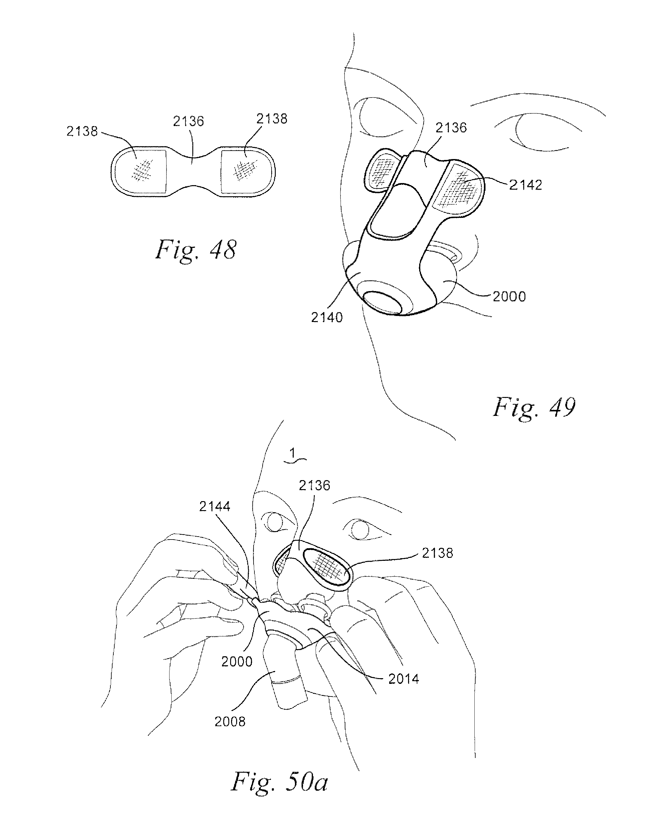
D00022

D00023

D00024

D00025

D00026

D00027

D00028

D00029

D00030

D00031

D00032

D00033

D00034

D00035
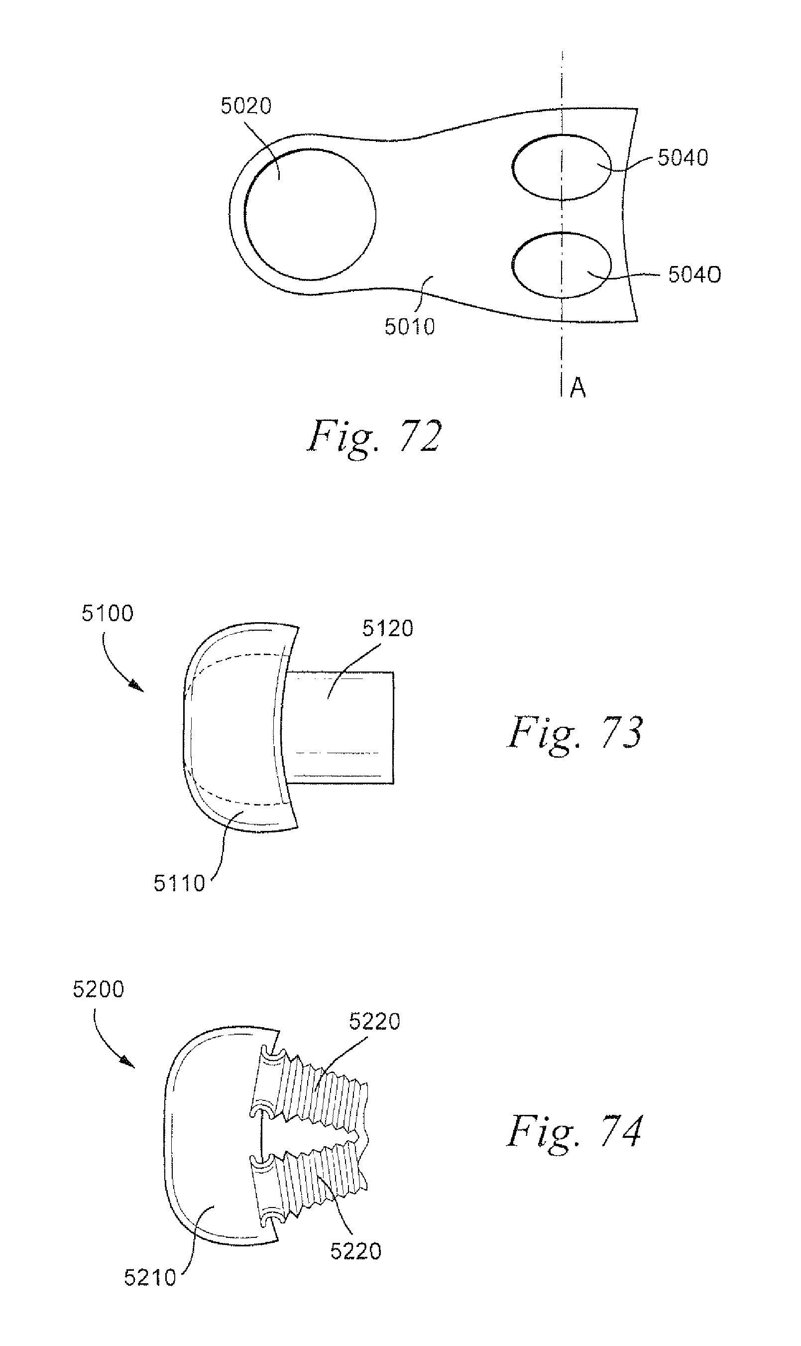
D00036

D00037

D00038

D00039

D00040

D00041

D00042

D00043

D00044

D00045

D00046

D00047

D00048

D00049

D00050

D00051

D00052

D00053
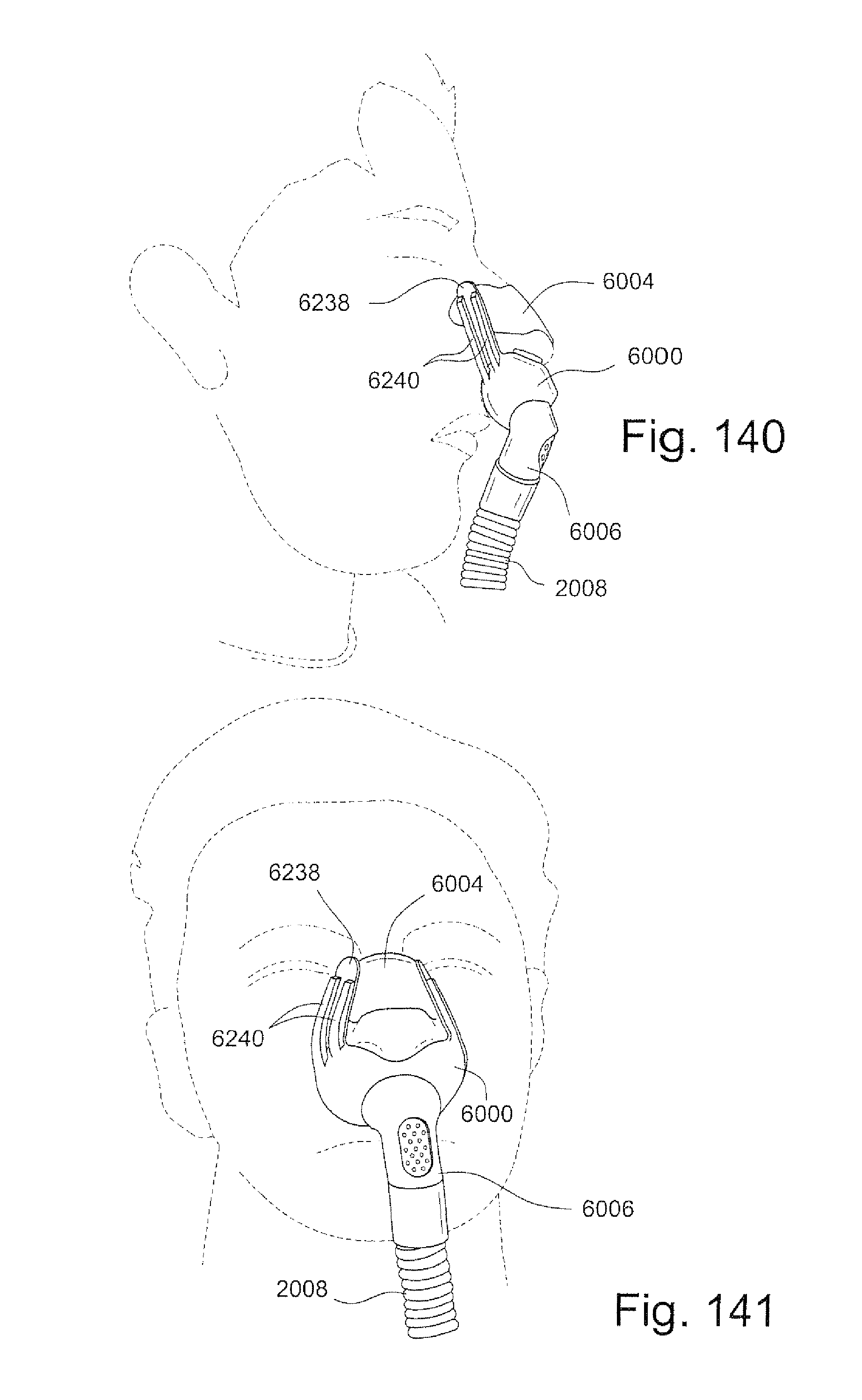
D00054

D00055

D00056
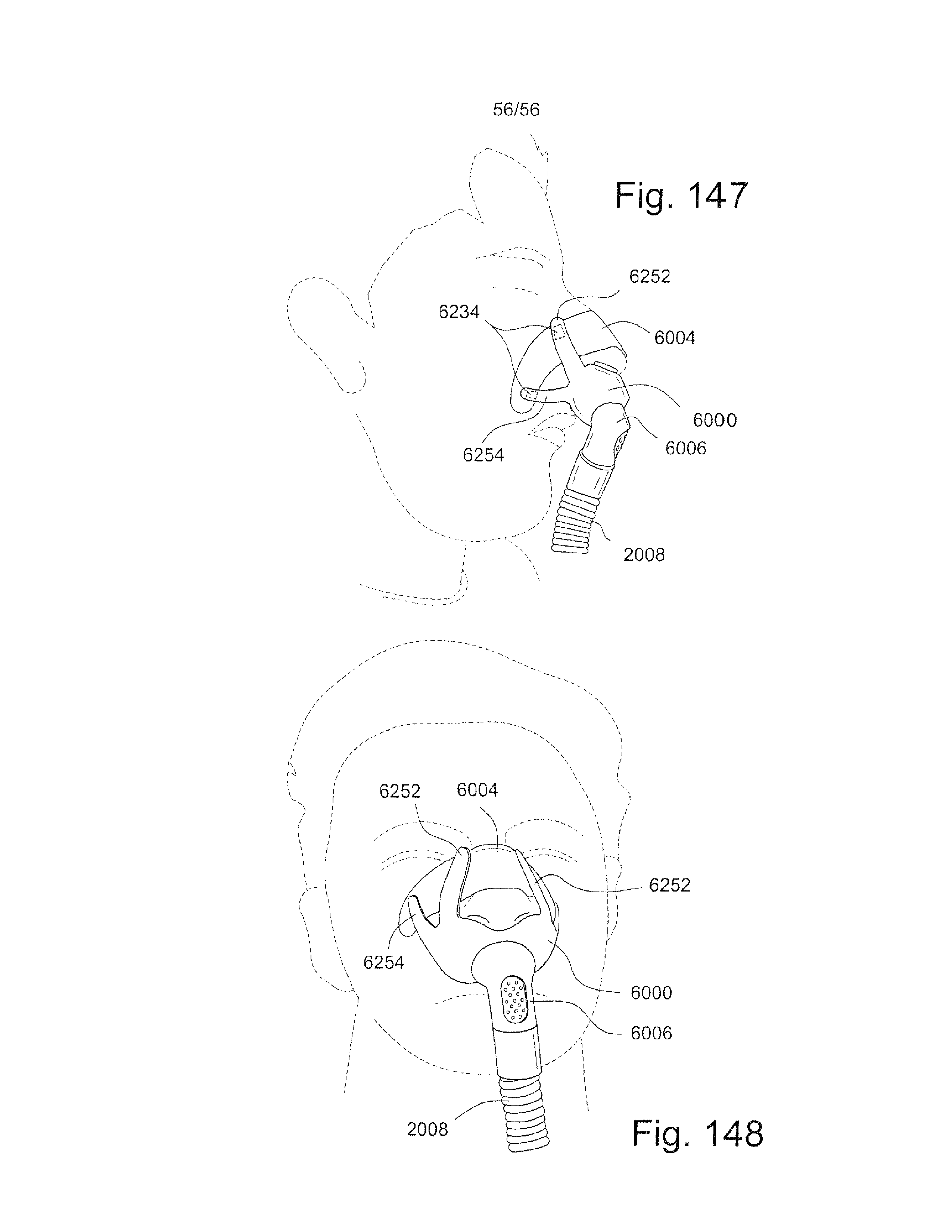
XML
uspto.report is an independent third-party trademark research tool that is not affiliated, endorsed, or sponsored by the United States Patent and Trademark Office (USPTO) or any other governmental organization. The information provided by uspto.report is based on publicly available data at the time of writing and is intended for informational purposes only.
While we strive to provide accurate and up-to-date information, we do not guarantee the accuracy, completeness, reliability, or suitability of the information displayed on this site. The use of this site is at your own risk. Any reliance you place on such information is therefore strictly at your own risk.
All official trademark data, including owner information, should be verified by visiting the official USPTO website at www.uspto.gov. This site is not intended to replace professional legal advice and should not be used as a substitute for consulting with a legal professional who is knowledgeable about trademark law.