Blade fixation for ankle fusion and arthroplasty
Butters , et al.
U.S. patent number 10,238,426 [Application Number 15/339,415] was granted by the patent office on 2019-03-26 for blade fixation for ankle fusion and arthroplasty. This patent grant is currently assigned to Engage Medical Holdings, LLC. The grantee listed for this patent is ENGAGE MEDICAL HOLDINGS, LLC. Invention is credited to Jeffery D. Arnett, Hyun Bae, Joshua A. Butters.


View All Diagrams
| United States Patent | 10,238,426 |
| Butters , et al. | March 26, 2019 |
Blade fixation for ankle fusion and arthroplasty
Abstract
Systems for lower extremity fusion and arthroplasty include fusion spacers, bone plates, and articular prostheses fixed to bone by blade anchors. Examples are shown for anterior, lateral, and medial approaches.
| Inventors: | Butters; Joshua A. (Chandler, AZ), Arnett; Jeffery D. (Gilbert, AZ), Bae; Hyun (Santa Monica, CA) | ||||||||||
|---|---|---|---|---|---|---|---|---|---|---|---|
| Applicant: |
|
||||||||||
| Assignee: | Engage Medical Holdings, LLC
(Los Angeles, CA) |
||||||||||
| Family ID: | 48797837 | ||||||||||
| Appl. No.: | 15/339,415 | ||||||||||
| Filed: | October 31, 2016 |
Prior Publication Data
| Document Identifier | Publication Date | |
|---|---|---|
| US 20170042576 A1 | Feb 16, 2017 | |
Related U.S. Patent Documents
| Application Number | Filing Date | Patent Number | Issue Date | ||
|---|---|---|---|---|---|
| 13747791 | Jan 23, 2013 | 9480511 | |||
| 61589721 | Jan 23, 2012 | ||||
| Current U.S. Class: | 1/1 |
| Current CPC Class: | A61B 17/8061 (20130101); A61B 17/562 (20130101); A61F 2/4202 (20130101) |
| Current International Class: | A61F 2/42 (20060101); A61B 17/80 (20060101); A61B 17/56 (20060101) |
References Cited [Referenced By]
U.S. Patent Documents
| 3486505 | December 1969 | Morrison |
| 3641590 | February 1972 | Michele |
| 3650309 | March 1972 | Neuschotz |
| 3842825 | October 1974 | Wagner |
| 3848276 | November 1974 | Martinez |
| 3882917 | May 1975 | Orlomoski |
| 3896504 | July 1975 | Fischer |
| 3907017 | September 1975 | Stanwick |
| 3927503 | December 1975 | Wilson |
| 4011602 | March 1977 | Rybicki |
| 4047524 | September 1977 | Hall |
| 4260005 | April 1981 | Stencel |
| 4349955 | September 1982 | Keen |
| 4355429 | October 1982 | Mittelmeier |
| 4454875 | June 1984 | Pratt |
| 4484570 | November 1984 | Sutter |
| 4501269 | February 1985 | Bagby |
| D281814 | December 1985 | Pratt |
| 4570623 | February 1986 | Ellison |
| 4611581 | September 1986 | Steffee |
| 4642869 | February 1987 | Muller |
| 4681589 | July 1987 | Tronzo |
| 4716893 | January 1988 | Fischer |
| 4743256 | May 1988 | Brantigan |
| 4743262 | May 1988 | Tronzo |
| 4764067 | August 1988 | Kawashima |
| 4820305 | April 1989 | Harms |
| 4834757 | May 1989 | Brantigan |
| 4838891 | June 1989 | Branemark |
| 4848328 | July 1989 | Laboureau |
| 4865607 | September 1989 | Witzel |
| 4874389 | October 1989 | Downey |
| 4930962 | June 1990 | Reynolds |
| 4946378 | August 1990 | Hirayama |
| 4957496 | September 1990 | Schmidt |
| 5002576 | March 1991 | Fuhrmann |
| 5019103 | May 1991 | Van Zile |
| 5053038 | October 1991 | Sheehan |
| 5074880 | December 1991 | Mansat |
| 5147361 | September 1992 | Ojima |
| 5163960 | November 1992 | Bonutti |
| 5192324 | March 1993 | Kenna |
| 5192327 | March 1993 | Brantigan |
| 5306309 | April 1994 | Wagner |
| 5314477 | May 1994 | Marnay |
| 5352229 | October 1994 | Goble |
| 5366479 | November 1994 | McGarry |
| 5431658 | July 1995 | Moskovich |
| 5443515 | August 1995 | Cohen |
| 5449359 | September 1995 | Groiso |
| 5454814 | October 1995 | Comte |
| D364462 | November 1995 | Michelson |
| 5507816 | April 1996 | Bullivant |
| 5514180 | May 1996 | Heggeness |
| D378409 | March 1997 | Michelson |
| 5609635 | March 1997 | Michelson |
| 5658337 | August 1997 | Kohrs |
| 5660188 | August 1997 | Groiso |
| 5683394 | November 1997 | Rinner |
| 5702449 | December 1997 | McKay |
| 5709683 | January 1998 | Bagby |
| 5713899 | February 1998 | Marnay |
| 5769852 | June 1998 | Branemark |
| 5772661 | June 1998 | Michelson |
| 5776199 | July 1998 | Michelson |
| 5776202 | July 1998 | Copf |
| 5788701 | August 1998 | McCue |
| 5800550 | September 1998 | Sertich |
| 5853414 | December 1998 | Groiso |
| 5860973 | January 1999 | Michelson |
| 5885287 | March 1999 | Bagby |
| 5893889 | April 1999 | Harrington |
| 5893890 | April 1999 | Pisharodi |
| 5947999 | September 1999 | Groiso |
| 5993476 | November 1999 | Groiso |
| 6039762 | March 2000 | McKay |
| 6063121 | May 2000 | Xavier |
| 6080155 | June 2000 | Michelson |
| 6096080 | August 2000 | Nicholson |
| 6102949 | August 2000 | Biedermann |
| 6113638 | September 2000 | Williams |
| 6120503 | September 2000 | Michelson |
| 6136001 | October 2000 | Michelson |
| 6159214 | December 2000 | Michelson |
| 6224607 | May 2001 | Michelson |
| 6235059 | May 2001 | Benezech |
| 6241769 | June 2001 | Nicholson |
| 6241770 | June 2001 | Michelson |
| 6270498 | August 2001 | Michelson |
| 6302914 | October 2001 | Michelson |
| 6309421 | October 2001 | Pisharodi |
| 6325805 | December 2001 | Ogilvie |
| 6336928 | January 2002 | Guerin |
| 6364880 | April 2002 | Michelson |
| 6402785 | June 2002 | Zdeblick |
| 6413278 | July 2002 | Marchosky |
| 6432107 | August 2002 | Ferree |
| 6436098 | August 2002 | Michelson |
| 6447524 | September 2002 | Knodel |
| 6447544 | September 2002 | Michelson |
| 6447546 | September 2002 | Bramlet |
| 6458159 | October 2002 | Thalgott |
| 6478800 | November 2002 | Fraser |
| 6485517 | November 2002 | Michelson |
| 6506216 | January 2003 | McCue |
| 6537320 | March 2003 | Michelson |
| 6558423 | May 2003 | Michelson |
| 6558424 | May 2003 | Thalgott |
| 6582468 | June 2003 | Gauchet |
| 6599294 | July 2003 | Fuss |
| 6610093 | August 2003 | Pisharodi |
| 6620198 | September 2003 | Burstein |
| 6652533 | November 2003 | O'Neil |
| 6679887 | January 2004 | Nicholson |
| 6716245 | April 2004 | Pasquet |
| 6726720 | April 2004 | Ross |
| 6740118 | May 2004 | Eisermann |
| 6743256 | June 2004 | Mason |
| 6746450 | June 2004 | Wall |
| 6755841 | June 2004 | Fraser |
| 6767356 | July 2004 | Kanner |
| 6767367 | July 2004 | Michelson |
| 6770074 | August 2004 | Michelson |
| 6770096 | August 2004 | Bolger |
| 6773437 | August 2004 | Ogilvie |
| 6800093 | October 2004 | Nicholson |
| 6802863 | October 2004 | Lawson |
| 6827740 | December 2004 | Michelson |
| 6835208 | December 2004 | Marchosky |
| 6849093 | February 2005 | Michelson |
| 6875213 | April 2005 | Michelson |
| 6923810 | August 2005 | Michelson |
| 6923830 | August 2005 | Michelson |
| 6926718 | August 2005 | Michelson |
| 6942698 | September 2005 | Jackson |
| 6969390 | November 2005 | Michelson |
| 6972035 | December 2005 | Michelson |
| 6981975 | January 2006 | Michelson |
| 6989031 | January 2006 | Michelson |
| 7033394 | April 2006 | Michelson |
| 7041135 | May 2006 | Michelson |
| 7044972 | May 2006 | Mathys, Jr. |
| 7048766 | May 2006 | Ferree |
| 7056344 | June 2006 | Huppert |
| 7056345 | June 2006 | Kuslich |
| 7060097 | June 2006 | Fraser |
| 7066961 | June 2006 | Michelson |
| 7083623 | August 2006 | Michelson |
| 7083652 | August 2006 | McCue |
| 7087082 | August 2006 | Paul |
| 7112206 | September 2006 | Michelson |
| 7115146 | October 2006 | Boyer, II |
| 7118580 | October 2006 | Beyersdorff |
| 7128761 | October 2006 | Kuras |
| 7163560 | January 2007 | Mason |
| 7166110 | January 2007 | Yundt |
| 7166129 | January 2007 | Michelson |
| 7169182 | January 2007 | Errico |
| 7204852 | April 2007 | Marnay |
| 7235101 | June 2007 | Berry |
| 7235105 | June 2007 | Jackson |
| 7255698 | August 2007 | Michelson |
| 7320707 | January 2008 | Zucherman |
| 7326248 | February 2008 | Michelson |
| 7331995 | February 2008 | Eisermann |
| 7357817 | April 2008 | D'Alessio, II |
| 7364589 | April 2008 | Eisermann |
| 7396365 | July 2008 | Michelson |
| 7462196 | December 2008 | Fraser |
| 7481830 | January 2009 | Wall |
| 7481832 | January 2009 | Meridew |
| D586915 | February 2009 | Grim |
| 7491205 | February 2009 | Michelson |
| 7503933 | March 2009 | Michelson |
| 7503934 | March 2009 | Eisermann |
| 7503935 | March 2009 | Zucherman |
| D594986 | June 2009 | Miles |
| 7540882 | June 2009 | Michelson |
| 7556650 | July 2009 | Collins |
| 7572293 | August 2009 | Rhodes |
| 7588600 | September 2009 | Benzel |
| 7594931 | September 2009 | Louis |
| 7611538 | November 2009 | Belliard |
| 7658766 | February 2010 | Melkent |
| 7695516 | April 2010 | Zeegers |
| 7749271 | July 2010 | Fischer |
| 7763076 | July 2010 | Navarro |
| 7780676 | August 2010 | Lakin |
| 7837732 | November 2010 | Zucherman |
| 7850791 | December 2010 | Quadakkers |
| 7883510 | February 2011 | Kim |
| 7887563 | February 2011 | Cummins |
| 7896919 | March 2011 | Belliard |
| 7909871 | March 2011 | Abdou |
| 7918891 | April 2011 | Curran |
| 7966799 | June 2011 | Morgan |
| 8021403 | September 2011 | Wall |
| 8034076 | October 2011 | Criscuolo |
| 8100972 | January 2012 | Bruffey |
| 8100974 | January 2012 | Duggal |
| 8105389 | January 2012 | Berelsman |
| 8123757 | February 2012 | Zalenski |
| 8133283 | March 2012 | Wilson |
| 8157865 | April 2012 | Hochschuler |
| 8491598 | July 2013 | Crook |
| 8500747 | August 2013 | DeRidder |
| 8636191 | January 2014 | Meagher |
| 8747412 | June 2014 | Bae |
| 8808294 | August 2014 | Fox |
| 9254130 | February 2016 | Hollis |
| 9480511 | November 2016 | Butters |
| 2001/0000532 | April 2001 | Michelson |
| 2001/0010001 | July 2001 | Michelson |
| 2001/0010002 | July 2001 | Michelson |
| 2001/0010020 | July 2001 | Michelson |
| 2001/0037154 | November 2001 | Martin |
| 2001/0047207 | November 2001 | Michelson |
| 2001/0047208 | November 2001 | Michelson |
| 2002/0004683 | January 2002 | Michelson |
| 2002/0013624 | January 2002 | Michelson |
| 2002/0035400 | March 2002 | Bryan |
| 2002/0049447 | April 2002 | Li |
| 2002/0091390 | July 2002 | Michelson |
| 2002/0091392 | July 2002 | Michelson |
| 2002/0095155 | July 2002 | Michelson |
| 2002/0099376 | July 2002 | Michelson |
| 2002/0099378 | July 2002 | Michelson |
| 2002/0116065 | August 2002 | Jackson |
| 2002/0116165 | August 2002 | El-Ghoroury |
| 2002/0147454 | October 2002 | Neto |
| 2002/0147499 | October 2002 | Shea |
| 2002/0161443 | October 2002 | Michelson |
| 2002/0165613 | November 2002 | Lin |
| 2003/0023307 | January 2003 | Michelson |
| 2003/0040798 | February 2003 | Michelson |
| 2003/0045940 | March 2003 | Eberlein |
| 2003/0060884 | March 2003 | Fell et al. |
| 2003/0100949 | May 2003 | Michelson |
| 2003/0120344 | June 2003 | Michelson |
| 2003/0149483 | August 2003 | Michelson |
| 2003/0158553 | August 2003 | Michelson |
| 2003/0195517 | October 2003 | Michelson |
| 2003/0195561 | October 2003 | Carley |
| 2003/0195632 | October 2003 | Foley |
| 2004/0030336 | February 2004 | Khanna |
| 2004/0030339 | February 2004 | Wack |
| 2004/0034353 | February 2004 | Michelson |
| 2004/0064185 | April 2004 | Michelson |
| 2004/0073315 | April 2004 | Justin |
| 2004/0083005 | April 2004 | Jacobsson |
| 2004/0117018 | June 2004 | Michelson |
| 2004/0122518 | June 2004 | Rhoda |
| 2004/0133203 | July 2004 | Young |
| 2004/0148028 | July 2004 | Ferree |
| 2004/0176853 | September 2004 | Sennett |
| 2004/0193271 | September 2004 | Fraser |
| 2004/0199254 | October 2004 | Louis |
| 2004/0210313 | October 2004 | Michelson |
| 2004/0210314 | October 2004 | Michelson |
| 2004/0215203 | October 2004 | Michelson |
| 2004/0220668 | November 2004 | Eisermann |
| 2004/0220670 | November 2004 | Eisermann |
| 2004/0225295 | November 2004 | Zubok |
| 2004/0225365 | November 2004 | Eisermann |
| 2004/0230308 | November 2004 | Michelson |
| 2004/0249388 | December 2004 | Michelson |
| 2004/0254581 | December 2004 | Leclair |
| 2004/0254644 | December 2004 | Taylor |
| 2004/0260286 | December 2004 | Ferree |
| 2005/0004672 | January 2005 | Pafford |
| 2005/0014919 | January 2005 | Hatakeyama |
| 2005/0027300 | February 2005 | Hawkins |
| 2005/0038512 | February 2005 | Michelson |
| 2005/0038513 | February 2005 | Michelson |
| 2005/0043802 | February 2005 | Eisermann |
| 2005/0049600 | March 2005 | Groiso |
| 2005/0055031 | March 2005 | Lim |
| 2005/0125065 | June 2005 | Zucherman |
| 2005/0131545 | June 2005 | Chervitz |
| 2005/0143747 | June 2005 | Zubok |
| 2005/0149192 | July 2005 | Zucherman |
| 2005/0149193 | July 2005 | Zucherman |
| 2005/0165408 | July 2005 | Puno |
| 2005/0171606 | August 2005 | Michelson |
| 2005/0171607 | August 2005 | Michelson |
| 2005/0177239 | August 2005 | Steinberg |
| 2005/0187628 | August 2005 | Michelson |
| 2005/0187629 | August 2005 | Michelson |
| 2005/0192586 | September 2005 | Zucherman |
| 2005/0216083 | September 2005 | Michelson |
| 2005/0216089 | September 2005 | Michelson |
| 2005/0234555 | October 2005 | Sutton |
| 2005/0273108 | December 2005 | Groiso |
| 2005/0277933 | December 2005 | Wall |
| 2006/0004453 | January 2006 | Bartish |
| 2006/0058802 | March 2006 | Kofoed |
| 2006/0074421 | April 2006 | Bickley |
| 2006/0079961 | April 2006 | Michelson |
| 2006/0085071 | April 2006 | Lechmann |
| 2006/0095136 | May 2006 | McLuen |
| 2006/0111787 | May 2006 | Bailie |
| 2006/0116769 | June 2006 | Marnay |
| 2006/0122702 | June 2006 | Michelson |
| 2006/0129238 | June 2006 | Paltzer |
| 2006/0136061 | June 2006 | Navarro |
| 2006/0136063 | June 2006 | Zeegers |
| 2006/0142860 | June 2006 | Navarro |
| 2006/0149377 | July 2006 | Navarro |
| 2006/0149384 | July 2006 | Navarro |
| 2006/0167461 | July 2006 | Hawkins |
| 2006/0178745 | August 2006 | Bartish |
| 2006/0195097 | August 2006 | Evans |
| 2006/0212123 | September 2006 | Lechmann |
| 2006/0241641 | October 2006 | Albans |
| 2006/0259143 | November 2006 | Navarro |
| 2006/0259145 | November 2006 | Navarro |
| 2006/0259146 | November 2006 | Navarro |
| 2007/0010890 | January 2007 | Collazo |
| 2007/0050032 | March 2007 | Gittings |
| 2007/0055376 | March 2007 | Michelson |
| 2007/0073404 | March 2007 | Rashbaum |
| 2007/0093839 | April 2007 | Beckendorf |
| 2007/0106388 | May 2007 | Michelson |
| 2007/0118132 | May 2007 | Culbert |
| 2007/0118145 | May 2007 | Fischer |
| 2007/0123903 | May 2007 | Raymond |
| 2007/0142922 | June 2007 | Lewis |
| 2007/0185375 | August 2007 | Stad |
| 2007/0191850 | August 2007 | Kim |
| 2007/0233244 | October 2007 | Lopez |
| 2007/0239278 | October 2007 | Heinz |
| 2007/0288005 | December 2007 | Arnin |
| 2007/0288021 | December 2007 | Rickels |
| 2007/0299529 | December 2007 | Rhodes |
| 2008/0015702 | January 2008 | Lakin |
| 2008/0051901 | February 2008 | de Villiers |
| 2008/0051902 | February 2008 | Dwyer |
| 2008/0103598 | May 2008 | Trudeau |
| 2008/0108997 | May 2008 | Berrevoets |
| 2008/0132949 | June 2008 | Aferzon |
| 2008/0140208 | June 2008 | Zucherman |
| 2008/0147203 | June 2008 | Cronin |
| 2008/0154377 | June 2008 | Voellmicke |
| 2008/0167721 | July 2008 | Bao |
| 2008/0177275 | July 2008 | Wing |
| 2008/0208345 | August 2008 | Hurlbert |
| 2008/0249575 | October 2008 | Waugh |
| 2008/0249623 | October 2008 | Bao |
| 2008/0269764 | October 2008 | Blain |
| 2008/0275455 | November 2008 | Berry |
| 2008/0287957 | November 2008 | Hester |
| 2009/0005784 | January 2009 | Blain |
| 2009/0005870 | January 2009 | Hawkins |
| 2009/0048604 | February 2009 | Milz |
| 2009/0062921 | March 2009 | Michelson |
| 2009/0088849 | April 2009 | Armstrong |
| 2009/0099601 | April 2009 | Aferzon |
| 2009/0099602 | April 2009 | Aflatoon |
| 2009/0164020 | June 2009 | Janowski |
| 2009/0209967 | August 2009 | Evans |
| 2009/0240333 | September 2009 | Trudeau |
| 2010/0004747 | January 2010 | Lin |
| 2010/0069958 | March 2010 | Sullivan |
| 2010/0185287 | July 2010 | Allard |
| 2010/0185292 | July 2010 | Hochschuler |
| 2010/0201739 | August 2010 | Yamaguchi |
| 2010/0204737 | August 2010 | Bae |
| 2010/0204739 | August 2010 | Bae |
| 2011/0022176 | January 2011 | Zucherman |
| 2011/0098819 | April 2011 | Eisermann |
| 2011/0160766 | June 2011 | Hendren |
| 2011/0160866 | June 2011 | Laurence |
| 2011/0166608 | July 2011 | Duggal |
| 2012/0191204 | July 2012 | Bae |
| 2012/0215315 | August 2012 | Hochschuler |
| 2012/0239098 | September 2012 | Bae |
| 2012/0253406 | October 2012 | Bae |
| 2012/0265259 | October 2012 | LaPosta |
| 2012/0283837 | November 2012 | Bae |
| 2013/0013006 | January 2013 | Rashbaum |
| 2013/0123863 | May 2013 | Hollis |
| 2013/0190827 | July 2013 | Butters |
| 2013/0267956 | October 2013 | Terrill |
| 2014/0039632 | February 2014 | Hollis |
| 2016/0157906 | June 2016 | Hollis |
| 0179695 | Apr 1986 | EP | |||
| 1327423 | Jul 2003 | EP | |||
| 1790298 | May 2007 | EP | |||
| 1827318 | Sep 2007 | EP | |||
| 1872746 | Jan 2008 | EP | |||
| 1897517 | Mar 2008 | EP | |||
| 1983941 | Oct 2008 | EP | |||
| 2651341 | Oct 2013 | EP | |||
| 2685938 | Aug 2015 | EP | |||
| 3178448 | Jun 2017 | EP | |||
| WO1993022990 | Nov 1993 | WO | |||
| WO2000025707 | May 2000 | WO | |||
| WO2000064360 | Nov 2000 | WO | |||
| WO2001003570 | Jan 2001 | WO | |||
| WO2002003885 | Jan 2002 | WO | |||
| WO2002003895 | Jan 2002 | WO | |||
| WO2002058593 | Aug 2002 | WO | |||
| WO2003005939 | Jan 2003 | WO | |||
| WO2003039400 | May 2003 | WO | |||
| WO2003053290 | Jul 2003 | WO | |||
| WO2003065930 | Aug 2003 | WO | |||
| WO2003092507 | Nov 2003 | WO | |||
| WO2004071359 | Aug 2004 | WO | |||
| WO2004080355 | Sep 2004 | WO | |||
| WO2004089240 | Oct 2004 | WO | |||
| WO2004108015 | Dec 2004 | WO | |||
| WO2005051243 | Jun 2005 | WO | |||
| WO2005074841 | Aug 2005 | WO | |||
| WO2006051547 | May 2006 | WO | |||
| WO2006074414 | Jul 2006 | WO | |||
| WO2006086494 | Aug 2006 | WO | |||
| WO2006120505 | Nov 2006 | WO | |||
| WO2006122194 | Nov 2006 | WO | |||
| WO2007028098 | Mar 2007 | WO | |||
| WO2007034310 | Mar 2007 | WO | |||
| WO2007087366 | Aug 2007 | WO | |||
| WO2008014258 | Jan 2008 | WO | |||
| WO2008014453 | Jan 2008 | WO | |||
| WO2008021955 | Feb 2008 | WO | |||
| WO2008034140 | Mar 2008 | WO | |||
| WO2008128367 | Oct 2008 | WO | |||
| WO2009070721 | Jun 2009 | WO | |||
| WO2010039026 | Apr 2010 | WO | |||
| WO2010121002 | Oct 2010 | WO | |||
| WO2011044879 | Apr 2011 | WO | |||
| WO2011090508 | Jul 2011 | WO | |||
| WO2012083205 | Jun 2012 | WO | |||
| WO2012112598 | Aug 2012 | WO | |||
Attorney, Agent or Firm: Maywood IP Law Bray; Stuart S. Meibos; David
Parent Case Text
CROSS-REFERENCE TO RELATED APPLICATIONS
This application is a continuation of:
U.S. patent application Ser. No. 13/747,791, filed Jan. 23, 2013, entitled BLADE FIXATION FOR ANKLE FUSION AND ARTHROPASTY, which is pending.
U.S. patent application Ser. No. 13/747,791 claims the benefit of:
U.S. Provisional Patent Application No. 61/589,721, filed Jan. 23, 2012, entitled BLADE FIXATION FOR ANKLE FUSION AND ARTHROPASTY.
The above-referenced documents are hereby incorporated by reference in their entirety.
This application incorporates by reference the following document in its entirety:
U.S. patent application Ser. No. 12/640,892, filed Dec. 17, 2009, entitled INTERVERTEBRAL IMPLANT WITH INTEGRATED FIXATION, which issued as U.S. Pat. No. 8,821,555 on Sep. 2, 2014.
Claims
The invention claimed is:
1. A system comprising: an implant body comprising a concave surface configured to contact bone and a channel extending across the concave surface between a leading portion of the channel and a trailing portion of the channel, wherein the channel comprises an undercut keyway, wherein the undercut keyway is discontinuous between the trailing portion of the channel and the leading portion of the channel; and an anchor comprising a fixation feature for engaging bone, a connecting feature extending along a length of the anchor, and an intermediate portion connecting the fixation feature to the connecting feature, wherein the connecting feature comprises a leading part and a trailing part, wherein the leading part of the connecting feature is discontinuous from the trailing part of the connection feature; wherein the channel and the connecting feature have complementary interconnecting shapes, wherein the connecting feature slidingly engages the channel to couple the anchor to the implant body; wherein, when the anchor is coupled to the implant body, the leading part of the connecting feature is fixed in the leading portion of the channel, the trailing part of the connecting feature is fixed in the trailing portion of the channel, at least a portion of the connecting feature between the leading and trailing portions of the channel is carried outside the concave surface, and the fixation feature is carried outside the implant body.
2. The system of claim 1, wherein the channel comprises a slot extending from the undercut keyway outwardly through the concave surface, wherein the undercut keyway comprises a first wall and a second wall opposite the first wall, wherein the slot extends through the first wall, wherein the concave surface intersects a portion of the first wall.
3. The system of claim 2, wherein the channel has a longitudinal axis, which is oblique to the concave surface at the second wall.
4. The system of claim 2, wherein the concave surface intersects a portion of the second wall.
5. The system of claim 1, wherein the implant body is an ankle fusion spacer.
6. The system of claim 1, wherein the implant body is an ankle arthroplasty component.
7. A system comprising: an implant body comprising a concave surface configured to contact bone and a channel extending across the concave surface between a leading portion of the channel and a trailing portion of the channel, wherein the channel comprises an undercut keyway, wherein the undercut keyway is discontinuous and separates the trailing portion of the channel from the leading portion of the channel; and an anchor comprising a fixation feature for engaging bone, a connecting feature extending along a length of the anchor, and an intermediate portion connecting the fixation feature to the connecting feature, wherein the connecting feature comprises a leading part and a trailing part, wherein the leading part of the connecting feature is discontinuous from the trailing part of the connecting feature; wherein the channel and the connecting feature have complementary interconnecting shapes, wherein the connecting feature slidingly engages the channel to couple the anchor to the implant body; wherein, when the anchor is coupled to the implant body, the leading part of the connecting feature is fixed in the leading portion of the channel, the trailing part of the connecting feature is fixed in the trailing portion of the channel, at least a portion of the connecting feature between the leading and trailing portions of the channel is carried outside the concave surface, and the fixation feature is carried outside the implant body.
8. The system of claim 7, wherein the channel comprises a slot extending from the undercut keyway outwardly through the concave surface, wherein the undercut keyway comprises a first wall and a second wall opposite the first wall, wherein the slot extends through the first wall, wherein the concave surface intersects a portion of the first wall.
9. The system of claim 8, wherein the channel has a longitudinal axis, which is oblique to the concave surface at the second wall.
10. The system of claim 8, wherein the concave surface intersects a portion of the second wall.
11. The system of claim 7, wherein the implant body is an ankle fusion spacer.
12. The system of claim 7, wherein the implant body is an ankle arthroplasty component.
13. A system comprising: an implant body comprising a concave surface configured to contact bone and a channel extending across the concave surface between a leading portion of the channel and a trailing portion of the channel, wherein the channel comprises an undercut keyway and a middle portion, wherein the middle portion of the channel is between the leading and trailing portions of the channel, so that the channel is discontinuous between the leading portion of the channel and the trailing portion of the channel; and an anchor comprising a fixation feature for engaging bone, a connecting feature extending along a length of the anchor, and an intermediate portion connecting the fixation feature to the connecting feature, wherein the connecting feature comprises a leading part and a trailing part, wherein the leading part of the connecting feature is discontinuous from the trailing part of the connecting feature; wherein the channel and the connecting feature have complementary interconnecting shapes, wherein the connecting feature slidingly engages the channel to couple the anchor to the implant body; wherein, when the anchor is coupled to the implant body, the leading part of the connecting feature is fixed in the leading portion of the channel, the trailing part of the connecting feature is fixed in the trailing portion of the channel, at least a portion of the connecting feature between the leading and trailing portions of the channel is carried outside the concave surface, and the fixation feature is carried outside the implant body.
14. The system of claim 13, wherein the channel comprises a slot extending from the undercut keyway outwardly through the concave surface, wherein the undercut keyway comprises a first wall and a second wall opposite the first wall, wherein the slot extends through the first wall, wherein the concave surface intersects a portion of the first wall.
15. The system of claim 14, wherein the channel has a longitudinal axis, which is oblique to the concave surface at the second wall.
16. The system of claim 14, wherein the concave surface intersects a portion of the second wall.
17. The system of claim 13, wherein the implant body is selected from the group consisting of an ankle fusion spacer and an ankle arthroplasty component.
Description
BACKGROUND
Ankle fusion rates are negatively affected, and ankle arthroplasty revision rates increase, due to the loads, stresses, high range of motion, and complex motion of the ankle joint. Secure fixation of the ankle during fusion and secure fixation of the ankle arthroplasty components contribute to the success of the procedure by preventing post-operative loosening or subsidence of components. Leg-length discrepancies are also common pre- and post-operatively, thus there is a need to restore leg length with a fusion or arthroplasty implant. There is also a need for easy, repeatable, secure ankle fixation devices and methods.
SUMMARY
@In an aspect of the technology, a system includes a first implant body with a first bone-contacting surface and a first channel on the first bone-contacting surface; and a first anchor coupled to the first implant body, the first anchor including a first bone fixation feature carried outside the first implant body, a first connecting feature fixed in the first channel, and a first intermediate portion connecting the first bone fixation feature to the first connecting feature, wherein the first intermediate portion extends through the first bone-contacting surface; wherein the first channel and the first connecting feature have complementary interconnecting shapes, wherein the first connecting feature slidingly engages the first channel to couple the first anchor to the first implant body.
In an embodiment, the system includes a second anchor like the first anchor; wherein the second anchor is coupled to the first implant body.
In another embodiment, the second anchor is coupled to the first channel.
In yet another embodiment, the second anchor is coupled to a second channel on a second bone-contacting surface of the body.
In yet another embodiment, the second anchor is coupled to a second channel on the first bone-contacting surface.
In yet another embodiment, the system includes a third anchor like the first anchor; wherein the third anchor is coupled to the first implant body.
In yet another embodiment, the third anchor is coupled to a third channel on a second bone-contacting surface of the body.
In yet another embodiment, the system includes a fourth anchor like the first anchor; wherein the fourth anchor is coupled to the first implant body.
In yet another embodiment, the fourth anchor is coupled to a fourth channel on the second bone-contacting surface of the body.
BRIEF DESCRIPTION OF THE DRAWINGS
While exemplary embodiments of the present technology have been shown and described in detail below, it will be clear to the person skilled in the art that changes and modifications may be made without departing from its scope. As such, that which is set forth in the following description and accompanying drawings is offered by way of illustration only and not as a limitation. The actual scope of the invention is intended to be defined by the following claims, along with the full range of equivalents to which such claims are entitled.
In addition, one of ordinary skill in the art will appreciate upon reading and understanding this disclosure that other variations for the technology described herein can be included within the scope of the present technology.
In the following Detailed Description, various features are grouped together in several embodiments for the purpose of streamlining the disclosure. This method of disclosure is not to be interpreted as reflecting an intention that exemplary embodiments of the technology require more features than are expressly recited in each claim. Rather, as the following claims reflect, inventive subject matter lies in less than all features of a single disclosed embodiment. Thus, the following claims are hereby incorporated into the Detailed Description, with each claim standing on its own as a separate embodiment.
Identical reference numerals do not necessarily indicate an identical structure. Rather, the same reference numeral may be used to indicate a similar feature or a feature with similar functionality. Not every feature of each embodiment is labeled in every figure in which that embodiment appears, in order to keep the figures clear. Similar reference numbers (e.g., those that are identical except for the first numeral) are used to indicate similar features in different embodiments.
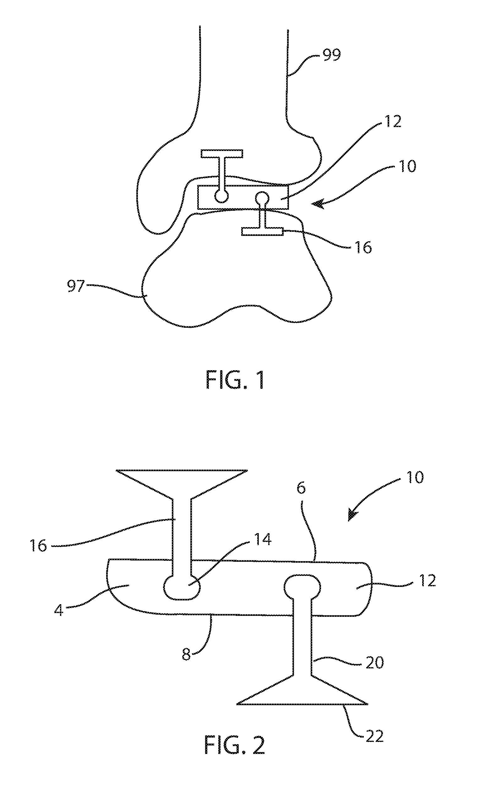
FIG. 1 is a front view of a left tibiotalar joint with a fusion spacer secured within the joint;
FIG. 2 is a front view of the fusion spacer of FIG. 1;
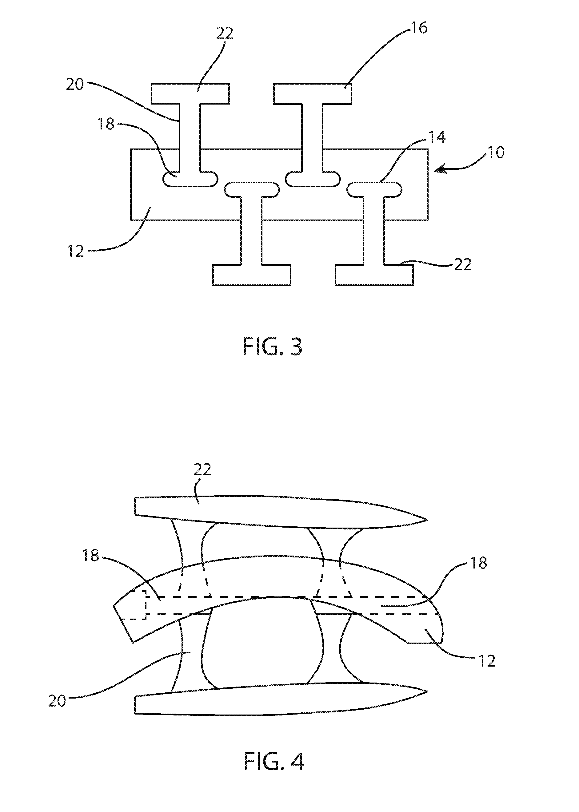
FIG. 3 is a front view of another fusion spacer;
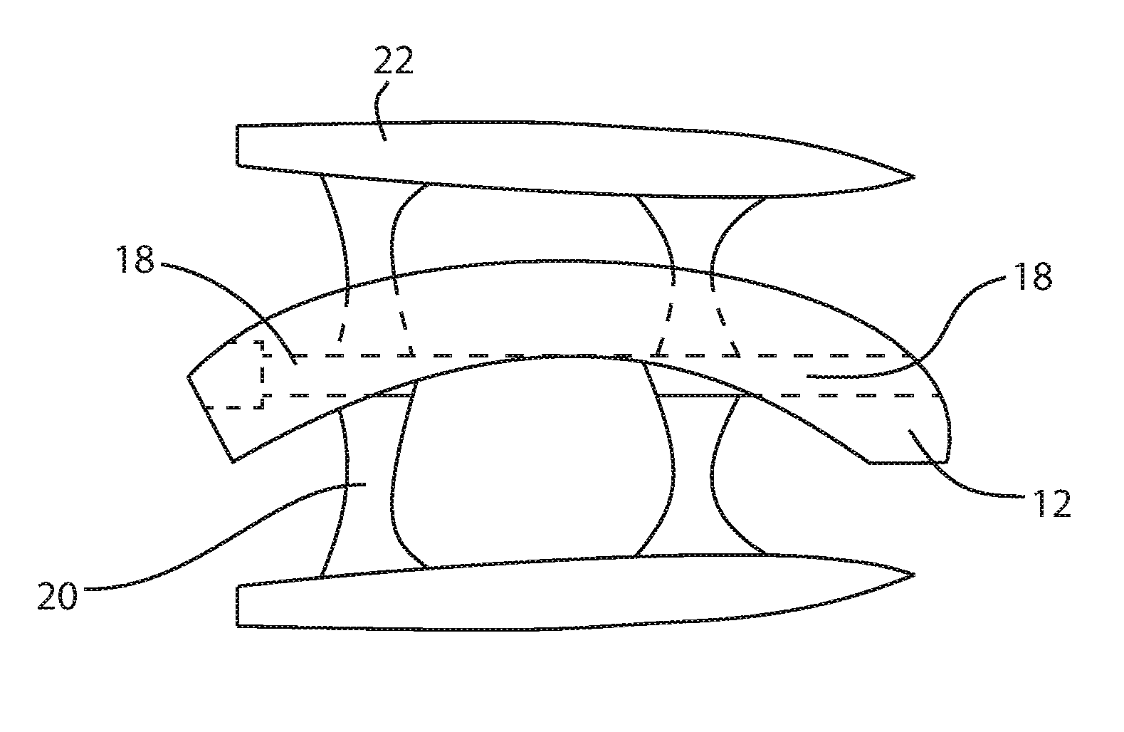
FIG. 4 is a side view of the fusion spacer of FIG. 1;
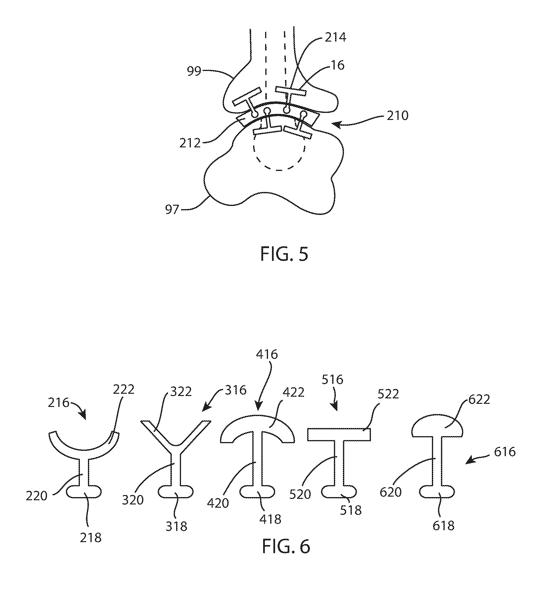
FIG. 5 is a side view of a left tibiotalar joint with yet another fusion spacer secured within the joint;
FIG. 6 is a front view of a set of anchors, each having a different cross sectional shape;
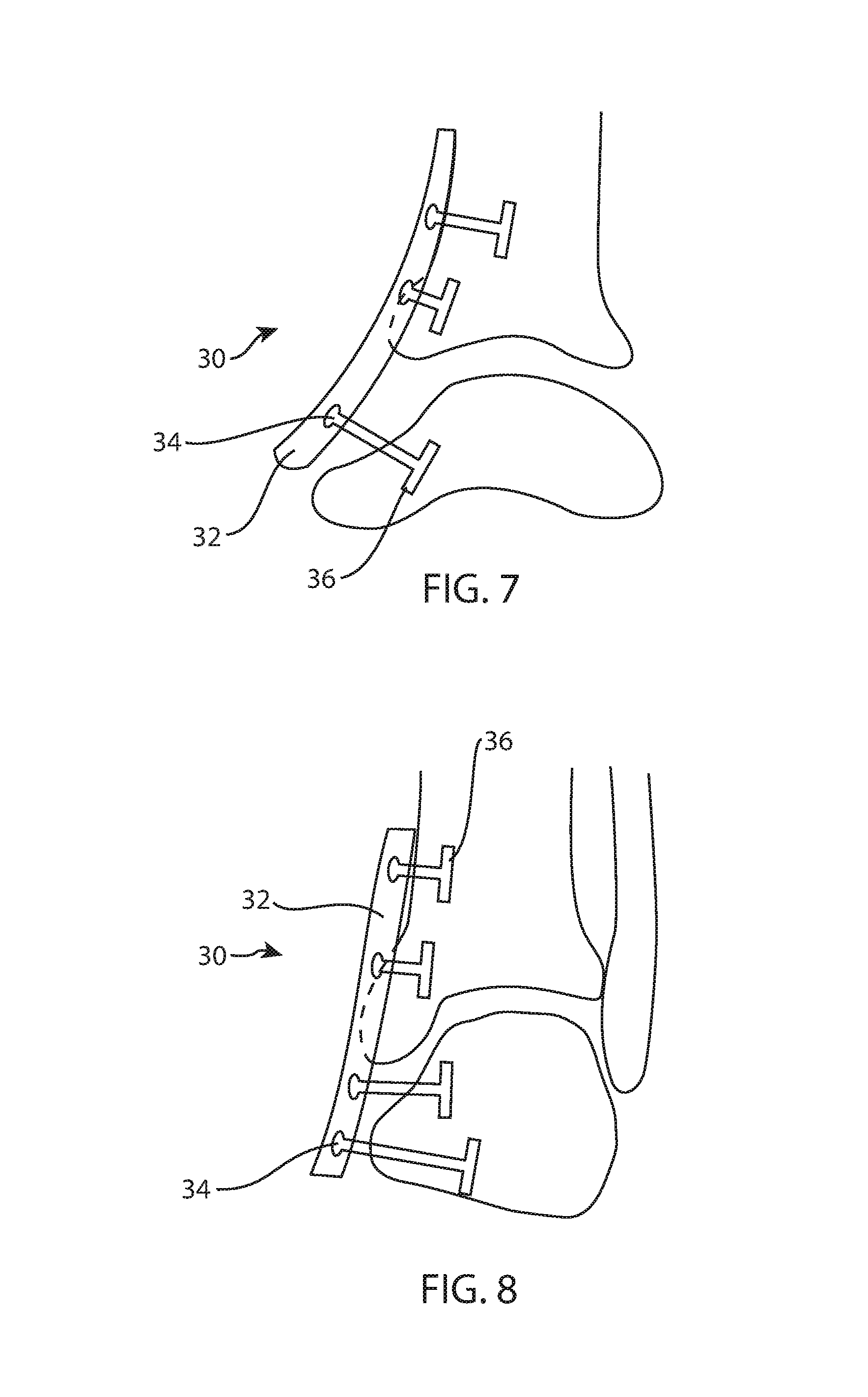
FIG. 7 is a side view of a left tibiotalar joint with a fusion plate secured across the joint;
FIG. 8 is a front view of a left tibiotalar joint with another fusion plate secured across the joint;
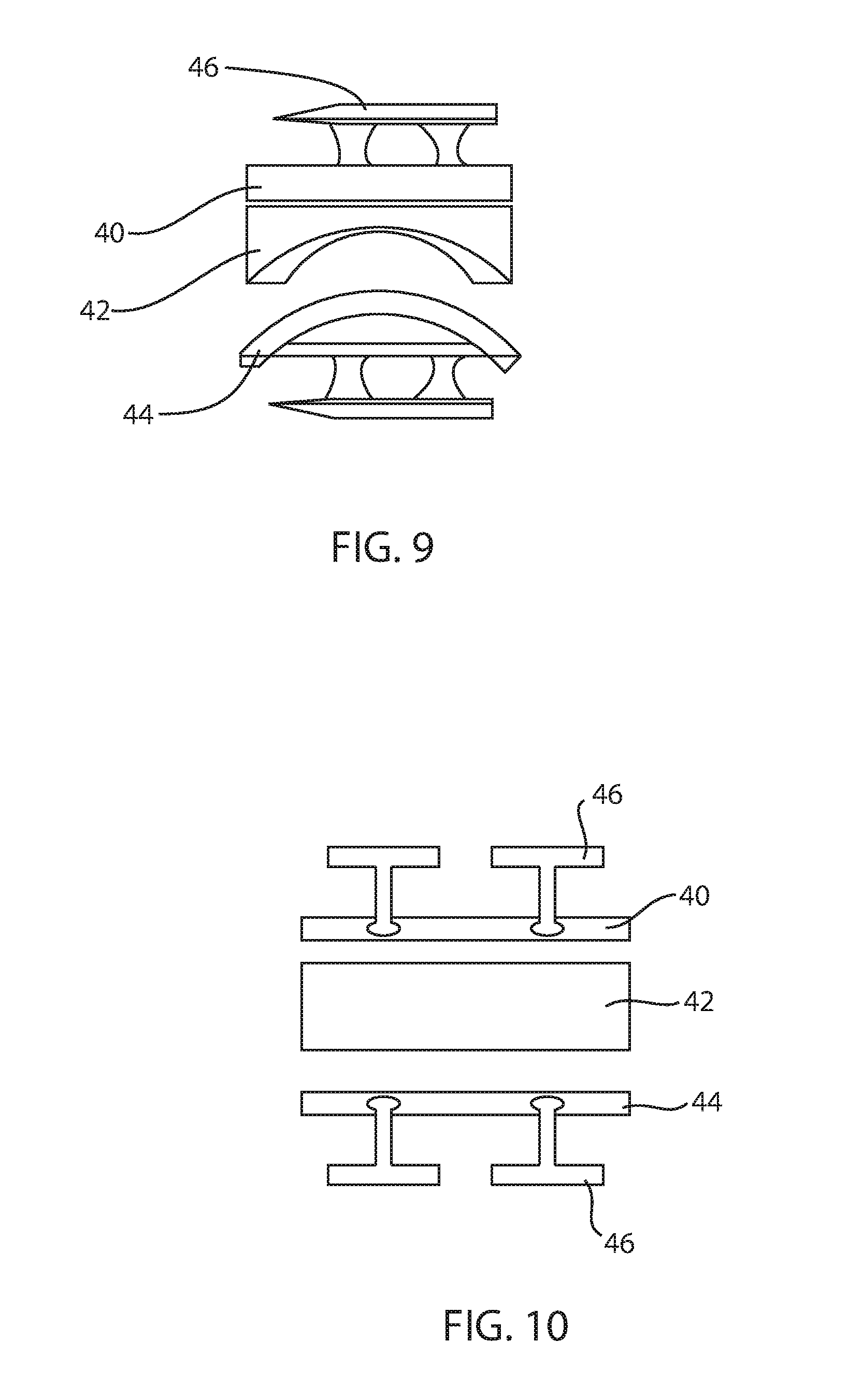
FIG. 9 is an exploded side view of an ankle arthroplasty device;
FIG. 10 is an exploded front view of the ankle arthroplasty device of FIG. 9;
FIG. 11 is an isometric view of a body of the fusion spacer of FIG. 1;
FIG. 12 is a front view of yet another fusion spacer;
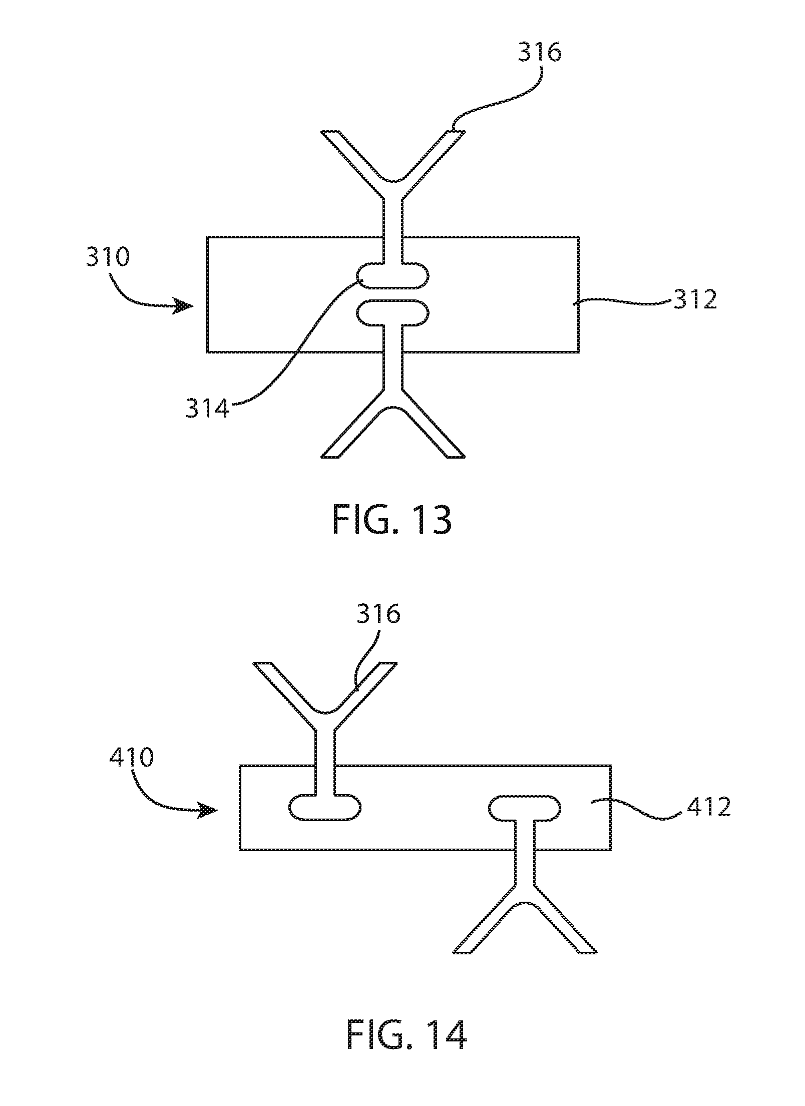
FIG. 13 is a front view of yet another fusion spacer;
FIG. 14 is a front view of yet another fusion spacer;
FIG. 15 is a side view of yet another fusion spacer;
FIG. 16 is a side view of yet another fusion spacer;
FIG. 17 is a side view of yet another fusion spacer;
FIG. 18 is a side view of the fusion spacer of FIG. 5;
FIG. 19 is a side view of yet another fusion spacer;
FIG. 20 is a side view of yet another fusion spacer; and
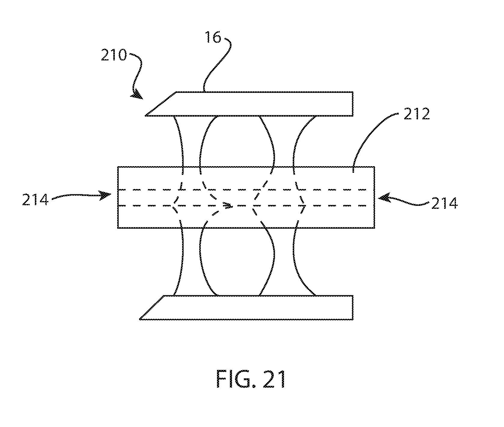
FIG. 21 is a front view of the fusion spacer of FIG. 5.
DETAILED DESCRIPTION
Standard medical planes of reference and descriptive terminology are employed in this specification. A sagittal plane divides a body into right and left portions. A mid-sagittal plane divides the body into equal right and left halves. A coronal plane divides a body into anterior and posterior portions. A transverse plane divides a body into superior and inferior portions. Anterior means toward the front of the body. Posterior means toward the back of the body. Superior means toward the head. Inferior means toward the feet. Medial means toward the midline of the body. Lateral means away from the midline of the body. Axial means toward a central axis of the body. Abaxial means away from a central axis of the body.
The present technology may be employed in a fusion spacer with integrated blade anchor fixation. The spacer includes a body disposed between at least two bones or bone portions. The body includes channels to accept one or more fixation blades, or anchors, per bone/implant interface. In other words, the body includes at least one channel on each bone-contacting surface, and may include more than one channel per bone-contacting surface. Each channel may accept one or more fixation blade anchors. The body may also include at least one hole or fenestration that extends between bone-contacting surfaces. The hole may be centrally located. The hole may contain bone fusion material, such as autograft bone, allograft bone, demineralized bone matrix (DBM), osteoconductive, or osteoinductive agents, among others. Each fixation blade, or anchor, may slide into a corresponding channel, and at the same time, into an adjacent portion of bone. The fixation blade, or anchor, may be impacted into the channel and bone portion. The fixation blade anchor may lock to the fusion spacer upon insertion so that the anchor may not migrate or be unintentionally removed from the fusion spacer. The anchor and/or fusion spacer may include integrated locking features or mechanisms so that locking occurs automatically as the anchor reaches full insertion. As the fixation blade, or anchor, advances into the channel and bone portion, the body and bone portion may be urged into compression. Additional fixation devices may also be included, such as pegs, stems, keels, screws, and the like.
FIGS. 1-2, 4, and 11 illustrate an example of a fusion spacer for an anterior approach to an ankle joint. Fusion spacer 10 includes a body 12 that may be disposed between a tibia 99 and a talus 97 as shown in FIG. 1 in an anterior view of an ankle joint. This example may be implanted through an anterior approach, although other examples may be implanted through other approaches. The body 12 includes two bone-contacting surfaces 6, 8 and a perimeter surface 4 extending around the body between the bone-contacting surfaces. Surface 6 is a tibia-contacting surface and surface 8 is a talus-contacting surface. Surface 6 may be straight across in an anterior view (FIGS. 1-2) and may be convex in a lateral view (FIGS. 4 and 11) in order to approximate a distal articular surface of a tibia. Surface 8 may be straight across in an anterior view (FIGS. 1-2) and may be concave in a lateral view (FIGS. 4 and 11) in order to approximate a proximal articular surface of a talus. Surfaces 6, 8 may be sections of cylinders, or semi-cylindrical. In other examples, the bone-contacting surfaces may be shaped differently to suit the particular implantation site. The body 12 may also include at least one hole 11 or fenestration that extends between bone-contacting surfaces. The hole 11 may be centrally located or off-center. The hole 11 may contain bone fusion material, such as autograft bone, allograft bone, demineralized bone matrix (DBM), osteoconductive, or osteoinductive agents, among others. The body may include at least one channel 14 on each bone-contacting surface 6, 8. The body 12 may include a plurality of channels 14 that accept at least one fixation blade anchor 16 for each bone-implant interface. Each channel 14 may include an undercut keyway which is complementary to a portion of the blade anchor 16. The channels 14 in this example are oriented to extend in an anterior-posterior direction when the fusion spacer 10 is implanted.
The blade anchors 16 may include a connecting feature 18, such as a knob, hook, key, tee, dovetail, rail, or other feature designed for complementary interconnecting fit with the channel 14 on the spacer body 12. The blade anchors 16 may be substantially T-shaped, and include an elongated intermediate portion 20 and a bone fixation feature 22.
The anchors in the present disclosure may share some or all of the features of the anchors disclosed in U.S. patent application Ser. No. 12/640,892 to Bae, et al., which is incorporated by reference herein in its entirety.
In use, the distal tibia and proximal talus may be exposed from an anterior approach, and the bones prepared with cutting instruments, jigs, and other tools to remove damaged, diseased, or otherwise undesirable articular cartilage and/or bone. This bone preparation establishes resection surfaces on the tibia and talus, which may be geometric approximations or idealizations of the removed natural bone surfaces, or undamaged natural bone surfaces. The resection surfaces may also match or complement the corresponding bone-facing surfaces on the spacer body 12. In this example, a distal tibial resection surface (not shown) may be straight across in an anterior view and convex in a lateral view. A proximal talar resection surface (not shown) may be straight across in an anterior view and concave in a lateral view. Trial bodies may be inserted into the tibiotalar joint space from an anterior direction to determine an appropriate length, width, thickness, height, and/or varus/valgus tilt for the spacer body 12. The appropriately sized spacer body 12 may then be selected from a kit or set of spacer bodies and inserted into the joint space from an anterior direction. The anchors 16 may then be aligned with the corresponding channels 14 and slidingly inserted into the channels and adjacent bone portions from an anterior direction. Additional tools may be used in this step to facilitate anchor alignment and insertion.
Referring to FIG. 4, the connecting feature 18, or rail, may be interrupted or intermittent along the length of the blade anchor 16, or the rail may be continuous.
FIG. 6 illustrates some alternative configurations for the bone-anchoring blades 16, as viewed from an end, or in other words, along an insertion direction. Each of the alternative anchor configurations 216, 316, etc. is distinguished by a bone fixation feature 222, 322, etc. and a connection feature 218, 318, etc. coupled together by an intermediate portion 220, 320, etc. The intermediate portion is narrower than either the bone fixation feature or the connection feature. In other words, the bone fixation feature and the connection feature are each wider than the intermediate portion. This arrangement, in the illustrated examples and others like them, enables the anchor 16 (specifically the intermediate portion) to perform as a tension-compression member to transfer tensile and compressive loads between the body and the adjacent bone portion.
FIG. 3 illustrates another example of a fusion spacer 110 for anterior insertion. Spacer 110 includes a body 112 with two channels 114 on each bone-contacting surface 106, 108. In this example, the channels 114 alternate between surface 6 and surface 8 across a width of the body 112. Other characteristics of spacer 110 may be similar to, or identical to, those of spacer 10, including the orientation of the channels 114.
FIGS. 12-14 show yet more examples of fusion spacers for anterior approach to the ankle joint. FIG. 12 shows a fusion spacer 1010 with a body 1012 having channels 1014 directly opposite each other. FIG. 13 also shows a fusion spacer 310 with a body 312 having channels 314 directly opposite each other. This example includes anchor 316. FIG. 14 shows a spacer 410 with a body 412 and anchor 316. Body 412 may be identical to body 12.
FIGS. 5, 18, and 21 illustrate yet another example of a fusion spacer 210, this time for lateral or medial insertion. The spacer body 212 may resemble spacer 12, at least with regards to the bone-contacting surfaces 6, 8; the perimeter surface 4; and optionally the fenestration 11. However, in this example, channels 214 extend in a medial-lateral direction when the fusion spacer 210 is implanted. Like spacer 110, spacer 210 includes two channels on each bone-contacting surface, the channels alternating between the bone-contacting surfaces across a width of the body 212.
FIGS. 15-17 and 19-20 show yet more examples of fusion spacers for lateral or medial approach to the ankle joint. FIG. 15 shows a fusion spacer 510 with a body 512 carrying one anchor 16 on each bone-contacting surface 506, 508. FIG. 16 shows a fusion spacer 610 with a body 612 carrying one anchor 16 centrally located on bone-contacting surface 606 and two anchors 16 bilaterally offset from center of bone-contacting surface 608. FIG. 17 shows a fusion spacer 710 with an opposite configuration, in which body 712 carries one anchor 16 centrally located on bone-contacting surface 708 and two anchors 16 bilaterally offset from center of bone-contacting surface 706. FIG. 19 shows a fusion spacer 810 with a body 812 carrying two anchors 16 widely bilaterally offset from center of bone-contacting surface 806 and two anchors narrowly bilaterally offset from center of bone-contacting surface 808. FIG. 20 shows a fusion spacer 910 with an opposite configuration, in which body 912 carries carrying two anchors 16 widely bilaterally offset from center of bone-contacting surface 908 and two anchors narrowly bilaterally offset from center of bone-contacting surface 906. Other arrangements are contemplated, both symmetric and asymmetric.
The fusion spacers disclosed herein may be adapted for use in midfoot and/or forefoot fusion procedures, such as tarsometatarsal joint fusion, hallucal fracture fusion, and the like.
The present technology may be employed in a bone plate with integrated blade anchor fixation. The plate may extend across at least two bones or bone portions. For example, the plate may extend across two bones and a joint therebetween, or between two bone fragments and a fracture or intentional cut therebetween. The plate includes channels to accept one or more fixation blades, or anchors, per bone/implant interface. In other words, the plate includes at least one channel for each bone or bone fragment to be fixed to the plate, and may include more than one channel for each bone or bone fragment to be fixed to the plate. The bone plate may be said to have a separate bone-contacting surface, area, or region for each bone or bone fragment to be fixed to the plate. Each channel may accept one or more fixation blade anchors. Each fixation blade, or anchor, may slide into a corresponding channel, and at the same time, into an adjacent portion of bone. The fixation blade may be impacted into the channel and bone portion. The fixation blade anchor may lock to the bone plate upon insertion so that the anchor may not migrate or be unintentionally removed from the bone plate. The anchor and/or bone plate may include integrated locking features or mechanisms so that locking occurs automatically as the anchor reaches full insertion. As the fixation blade advances into the channel and bone portion, the plate and bone portion may be urged into compression. Additional fixation devices may also be included, such as pegs, stems, keels, screws, and the like.
FIG. 7 illustrates an example of a bone plate system 30 for anterior application across an ankle joint for fusion. Bone plate system 30 includes a plate body 32 that extends anteriorly across a distal portion of a tibia and a proximal portion of a talus with a plurality of channels 34 configured to receive one or more fixation blade anchors 36. The channels 34, blade anchors 36, and their configuration on the plate body 32 may be similar to those described above with regard to FIGS. 1-6 and 11-20. However, this example provides an opportunity to mention that any of the anchors disclosed herein may have different heights, or depth of penetration into an adjacent bone portion. Any of the blade anchor shapes or sizes disclosed herein may be used. The plate body 32 carries three anchors 34, the outermost anchors penetrating deeply into adjacent bone and the middle one penetrating relatively shallowly.
The fusion plate body 32 may also include at least one aperture to provide for bone fusion material. The aperture may be located anywhere along the plate body 32. For example, an aperture may be adjacent to a channel 34 or between two channels.
In use, the distal tibia and proximal talus may be exposed from an anterior approach. Optionally, the bones may be prepared with cutting instruments, jigs, and other tools to remove damaged, diseased, or otherwise undesirable periosteum, articular cartilage, and/or bone. This bone preparation establishes resection surfaces on the tibia and talus, which may be geometric approximations or idealizations of the removed natural bone surfaces, or undamaged natural bone surfaces. The resection surfaces may also match or complement the corresponding bone-facing surfaces on the plate body 32. In this example, however, extensive bone preparation is not shown. Trial plate bodies may be applied to the exposed tibiotalar region from an anterior direction to determine an appropriate length, width, thickness, height, and/or curvature for the plate body 32. Measuring instruments may be used instead of trials. The appropriately sized plate body 32 may then be selected from a kit or set of plate bodies and applied to the exposed tibiotalar region from an anterior direction. The anchors 36 may then be aligned with the corresponding channels 34 and inserted into the channels and adjacent bone portions from a lateral or medial direction. Additional tools may be used in this step to facilitate anchor alignment and insertion. In another example, the channels 34 may be oriented in an anterior-posterior direction and anchors 36 may be inserted along an anterior or posterior direction.
FIG. 8 illustrates another example of a bone plate system 130, this time for lateral or medial application across an ankle joint for fusion. The plate body 132 may at least partially resemble plate body 32. However, in this example, channels 134 extend in an anterior-posterior direction when the bone plate system 130 is implanted. This example further illustrates the anchors 136 having different depths of penetration into adjacent bone, or otherwise different lengths of protrusion from the plate body 132. The distal most anchor in this example has the greatest penetration, the proximal most two anchors have the least penetration, and the second from distal most anchor has an intermediate depth of penetration. In another example, the channels 134 may be oriented in a medial-lateral direction and anchors 136 may be inserted along a lateral or medial direction. When applied laterally, the tibia, talus, and/or fibula each may receive at least one blade anchor.
The bone plates disclosed herein may be adapted for use in midfoot and/or forefoot fusion procedures, such as fracture fixation, opening and/or closing wedge osteotomy fixation, joint fusion, and the like.
The present technology may be employed in an arthroplasty device with integrated blade anchor fixation. The arthroplasty device, or prosthesis, may include first and second endplates, or bone-contacting components, and an articular core disposed between the bone-contacting components. Each bone-contacting component includes at least one channel on each bone-contacting surface to accept one or more fixation blades, or anchors. In other words, each bone-contacting component includes at least one channel per bone/implant interface. More than one channel may be included on each bone-contacting surface. Each channel may accept one or more fixation blade anchors. Each fixation blade, or anchor, may slide into a corresponding channel, and at the same time, into an adjacent portion of bone. The fixation blade may be impacted into the channel and bone portion. The fixation blade anchor may lock to the bone-contacting component upon insertion so that the anchor may not migrate or be unintentionally removed from the bone-contacting component. The anchor and/or bone-contacting component may include integrated locking features or mechanisms so that locking occurs automatically as the anchor reaches full insertion. As the fixation blade advances into the channel and bone portion, the bone-contacting component and bone portion may be urged into compression. Additional fixation devices may also be included, such as pegs, stems, keels, screws, and the like.
As illustrated in FIGS. 9 and 10, an ankle arthroplasty prosthesis 41 includes a tibial endplate 40, an articulating core 42, and a talar endplate 44. Similar to the previously described examples, the tibial endplate 40 and the talar endplate 44 each may have at least one channel 45 in a bone-contacting surface. Each channel 45 may be configured to accept at least one fixation blade 46. Any of the blade anchor shapes or sizes disclosed herein may be used. The fixation blade anchors 46 may be inserted anteriorly, as shown in this example, or laterally or medially, by reorienting the channels as described above for the fusion spacers and/or bone plates. In practice, the fixation blades 46 may be impacted into the bone, resulting in compression between the endplate and the bone to achieve good compression to achieve good short-term and long-term fixation of the prosthesis. The surgical method may be similar to the method described above for fusion spacers.
The arthroplasty prostheses disclosed herein may be adapted for use in midfoot and/or forefoot arthroplasty procedures, such as hallux valgus, hammertoe, and the like.
The components disclosed herein may be made from metals, polymers, ceramics, glasses, composite materials, biological materials or tissues, or other biocompatible materials. Different materials may be used for individual components. Different materials may be combined in a single component.
It should be understood that the present system, kits, apparatuses, and methods are not intended to be limited to the particular forms disclosed. Rather, they are to cover all combinations, modifications, equivalents, and alternatives falling within the scope of the claims.
The claims are not to be interpreted as including means-plus- or step-plus-function limitations, unless such a limitation is explicitly recited in a given claim using the phrase(s) "means for" or "step for," respectively.
The term "coupled" is defined as connected, although not necessarily directly, and not necessarily mechanically.
The use of the word "a" or "an" when used in conjunction with the term "comprising" in the claims and/or the specification may mean "one," but it is also consistent with the meaning of "one or more" or "at least one." The term "about" means, in general, the stated value plus or minus 5%. The use of the term "or" in the claims is used to mean "and/or" unless explicitly indicated to refer to alternatives only or the alternative are mutually exclusive, although the disclosure supports a definition that refers to only alternatives and "and/or."
The terms "comprise" (and any form of comprise, such as "comprises" and "comprising"), "have" (and any form of have, such as "has" and "having"), "include" (and any form of include, such as "includes" and "including") and "contain" (and any form of contain, such as "contains" and "containing") are open-ended linking verbs. As a result, a method or device that "comprises," "has," "includes" or "contains" one or more steps or elements, possesses those one or more steps or elements, but is not limited to possessing only those one or more elements. Likewise, a step of a method or an element of a device that "comprises," "has," "includes" or "contains" one or more features, possesses those one or more features, but is not limited to possessing only those one or more features. Furthermore, a device or structure that is configured in a certain way is configured in at least that way, but may also be configured in ways that are not listed.
In the foregoing Detailed Description, various features are grouped together in several embodiments for the purpose of streamlining the disclosure. This method of disclosure is not to be interpreted as reflecting an intention that the embodiments of the invention require more features than are expressly recited in each claim. Rather, as the following claims reflect, inventive subject matter lies in less than all features of a single disclosed embodiment. Thus, the following claims are hereby incorporated into the Detailed Description, with each claim standing on its own as a separate embodiment.
* * * * *
D00000
D00001
D00002
D00003
D00004
D00005
D00006
D00007
D00008
D00009
D00010
D00011
XML
uspto.report is an independent third-party trademark research tool that is not affiliated, endorsed, or sponsored by the United States Patent and Trademark Office (USPTO) or any other governmental organization. The information provided by uspto.report is based on publicly available data at the time of writing and is intended for informational purposes only.
While we strive to provide accurate and up-to-date information, we do not guarantee the accuracy, completeness, reliability, or suitability of the information displayed on this site. The use of this site is at your own risk. Any reliance you place on such information is therefore strictly at your own risk.
All official trademark data, including owner information, should be verified by visiting the official USPTO website at www.uspto.gov. This site is not intended to replace professional legal advice and should not be used as a substitute for consulting with a legal professional who is knowledgeable about trademark law.