Adjustable annuloplasty device with alternating peaks and troughs
Kutzik , et al.
U.S. patent number 10,226,342 [Application Number 15/475,871] was granted by the patent office on 2019-03-12 for adjustable annuloplasty device with alternating peaks and troughs. This patent grant is currently assigned to Valtech Cardio, Ltd.. The grantee listed for this patent is VALTECH CARDIO, LTD.. Invention is credited to Haim Brauon, Alon Fogel, Ilia Hariton, Meir Kutzik, Michael Levin, Tal Reich.
View All Diagrams
| United States Patent | 10,226,342 |
| Kutzik , et al. | March 12, 2019 |
Adjustable annuloplasty device with alternating peaks and troughs
Abstract
Apparatus is provided, comprising a ring, comprising a plurality of struts arranged in a pattern of alternating peaks and troughs, each strut having a first end-portion and a second end-portion, each peak defined by convergence of adjacent first end-portions disposed at an angle with respect to each other, and each trough defined by convergence of adjacent second end-portions. The apparatus also comprises a plurality of anchors. Each anchor has a longitudinal axis, is configured to be driven along the longitudinal axis into tissue of the heart, and is coupled to the ring at a respective trough in a manner that facilitates (i) movement of the anchor along the longitudinal axis with respect to the trough, and (ii) deflection of the longitudinal axis with respect to the trough.
| Inventors: | Kutzik; Meir (Holon, IL), Brauon; Haim (Bat Yam, IL), Levin; Michael (Karmei Yosef, IL), Fogel; Alon (Beersheva, IL), Hariton; Ilia (Zichron Yaackov, IL), Reich; Tal (Moshav Moledet, IL) | ||||||||||
|---|---|---|---|---|---|---|---|---|---|---|---|
| Applicant: |
|
||||||||||
| Assignee: | Valtech Cardio, Ltd. (Or
Yehuda, IL) |
||||||||||
| Family ID: | 56891028 | ||||||||||
| Appl. No.: | 15/475,871 | ||||||||||
| Filed: | March 31, 2017 |
Prior Publication Data
| Document Identifier | Publication Date | |
|---|---|---|
| US 20180008409 A1 | Jan 11, 2018 | |
Foreign Application Priority Data
| Jul 8, 2016 [GB] | 1611910.9 | |||
| Current U.S. Class: | 1/1 |
| Current CPC Class: | A61F 2/2445 (20130101); A61F 2250/0006 (20130101); A61F 2250/0029 (20130101); A61F 2220/0016 (20130101); A61F 2250/0012 (20130101); A61F 2220/0091 (20130101); A61F 2250/0008 (20130101) |
| Current International Class: | A61F 2/24 (20060101) |
References Cited [Referenced By]
U.S. Patent Documents
| 3604488 | September 1971 | Wishart et al. |
| 3656185 | April 1972 | Carpentier |
| 3840018 | October 1974 | Heifetz |
| 3881366 | May 1975 | Bradley et al. |
| 3898701 | August 1975 | La Russa |
| 4042979 | August 1977 | Angell |
| 4118805 | October 1978 | Reimels |
| 4214349 | July 1980 | Munch |
| 4261342 | April 1981 | Aranguren Duo |
| 4290151 | September 1981 | Massana |
| 4434828 | March 1984 | Trincia |
| 4473928 | October 1984 | Johnson |
| 4602911 | July 1986 | Ahmadi et al. |
| 4625727 | December 1986 | Leiboff |
| 4712549 | December 1987 | Peters et al. |
| 4778468 | October 1988 | Hunt et al. |
| 4917698 | April 1990 | Carpentier et al. |
| 4961738 | October 1990 | Mackin |
| 5042707 | August 1991 | Taheri |
| 5061277 | October 1991 | Carpentier et al. |
| 5064431 | November 1991 | Gilbertson et al. |
| 5104407 | April 1992 | Lam et al. |
| 5108420 | April 1992 | Marks |
| 5201880 | April 1993 | Wright et al. |
| 5258008 | November 1993 | Wilk |
| 5300034 | April 1994 | Behnke et al. |
| 5325845 | July 1994 | Adair |
| 5346498 | September 1994 | Greelis et al. |
| 5383852 | January 1995 | Stevens-Wright |
| 5449368 | September 1995 | Kuzmak |
| 5450860 | September 1995 | O'Connor |
| 5464404 | November 1995 | Abela et al. |
| 5474518 | December 1995 | Farrer Velazquez |
| 5477856 | December 1995 | Lundquist |
| 5593424 | January 1997 | Northrup, III |
| 5601572 | February 1997 | Middleman et al. |
| 5626609 | May 1997 | Zvenyatsky et al. |
| 5643317 | July 1997 | Pavcnik et al. |
| 5669919 | September 1997 | Sanders et al. |
| 5676653 | October 1997 | Taylor et al. |
| 5683402 | November 1997 | Cosgrove et al. |
| 5702397 | December 1997 | Goble et al. |
| 5702398 | December 1997 | Tarabishy |
| 5709695 | January 1998 | Northrup, III |
| 5716370 | February 1998 | Williamson, IV et al. |
| 5716397 | February 1998 | Myers |
| 5728116 | March 1998 | Rosenman |
| 5730150 | March 1998 | Peppel et al. |
| 5749371 | May 1998 | Zadini et al. |
| 5782844 | July 1998 | Yoon et al. |
| 5810882 | September 1998 | Bolduc et al. |
| 5824066 | October 1998 | Gross |
| 5830221 | November 1998 | Stein et al. |
| 5843120 | December 1998 | Israel et al. |
| 5855614 | January 1999 | Stevens et al. |
| 5876373 | March 1999 | Giba et al. |
| 5935098 | August 1999 | Blaisdell et al. |
| 5957953 | September 1999 | DiPolo et al. |
| 5961440 | October 1999 | Schweich, Jr. et al. |
| 5961539 | October 1999 | Northrup, III et al. |
| 5984959 | November 1999 | Robertson et al. |
| 6042554 | March 2000 | Rosenman et al. |
| 6045497 | April 2000 | Schweich, Jr. et al. |
| 6050936 | April 2000 | Schweich, Jr. et al. |
| 6059715 | May 2000 | Schweich, Jr. et al. |
| 6074341 | June 2000 | Anderson et al. |
| 6074401 | June 2000 | Gardiner et al. |
| 6074417 | June 2000 | Peredo |
| 6086582 | July 2000 | Altman et al. |
| 6102945 | August 2000 | Campbell |
| 6106550 | August 2000 | Magovern et al. |
| 6110200 | August 2000 | Hinnenkamp |
| 6132390 | October 2000 | Cookston et al. |
| 6143024 | November 2000 | Campbell et al. |
| 6159240 | December 2000 | Sparer et al. |
| 6165119 | December 2000 | Schweich, Jr. et al. |
| 6174332 | January 2001 | Loch et al. |
| 6183411 | February 2001 | Mortier et al. |
| 6187040 | February 2001 | Wright |
| 6210347 | April 2001 | Forsell |
| 6217610 | April 2001 | Carpentier et al. |
| 6231602 | May 2001 | Carpentier et al. |
| 6251092 | June 2001 | Qin et al. |
| 6296656 | October 2001 | Bolduc et al. |
| 6315784 | November 2001 | Djurovic |
| 6319281 | November 2001 | Patel |
| 6328746 | December 2001 | Gambale |
| 6332893 | December 2001 | Mortier et al. |
| 6355030 | March 2002 | Aldrich et al. |
| 6361559 | March 2002 | Houser et al. |
| 6368348 | April 2002 | Gabbay |
| 6402780 | June 2002 | Williamson, IV et al. |
| 6406420 | June 2002 | McCarthy et al. |
| 6406493 | June 2002 | Tu et al. |
| 6419696 | July 2002 | Ortiz et al. |
| 6451054 | September 2002 | Stevens |
| 6458076 | October 2002 | Pruitt |
| 6461366 | October 2002 | Seguin |
| 6470892 | October 2002 | Forsell |
| 6503274 | January 2003 | Howanec, Jr. et al. |
| 6524338 | February 2003 | Gundry |
| 6530952 | March 2003 | Vesely |
| 6533772 | March 2003 | Sherts et al. |
| 6537314 | March 2003 | Langberg et al. |
| 6547801 | April 2003 | Dargent et al. |
| 6554845 | April 2003 | Fleenor et al. |
| 6564805 | May 2003 | Garrison et al. |
| 6565603 | May 2003 | Cox |
| 6569198 | May 2003 | Wilson et al. |
| 6579297 | June 2003 | Bicek et al. |
| 6589160 | July 2003 | Schweich, Jr. et al. |
| 6592593 | July 2003 | Parodi et al. |
| 6602288 | August 2003 | Cosgrove et al. |
| 6602289 | August 2003 | Colvin et al. |
| 6613078 | September 2003 | Barone |
| 6613079 | September 2003 | Wolinsky et al. |
| 6619291 | September 2003 | Hlavka et al. |
| 6626899 | September 2003 | Houser et al. |
| 6626917 | September 2003 | Craig |
| 6626930 | September 2003 | Allen et al. |
| 6629534 | October 2003 | St. Goar et al. |
| 6629921 | October 2003 | Schweich, Jr. et al. |
| 6651671 | November 2003 | Donlon et al. |
| 6652556 | November 2003 | VanTassel et al. |
| 6682558 | January 2004 | Tu et al. |
| 6689125 | February 2004 | Keith et al. |
| 6689164 | February 2004 | Seguin |
| 6695866 | February 2004 | Kuehn et al. |
| 6702826 | March 2004 | Liddicoat et al. |
| 6702846 | March 2004 | Mikus et al. |
| 6706065 | March 2004 | Langberg et al. |
| 6709385 | March 2004 | Forsell |
| 6709456 | March 2004 | Langberg et al. |
| 6711444 | March 2004 | Koblish |
| 6719786 | April 2004 | Ryan et al. |
| 6723038 | April 2004 | Schroeder et al. |
| 6726716 | April 2004 | Marquez |
| 6726717 | April 2004 | Alfieri et al. |
| 6730121 | May 2004 | Ortiz et al. |
| 6749630 | June 2004 | McCarthy et al. |
| 6752813 | June 2004 | Goldfarb et al. |
| 6764310 | July 2004 | Ichihashi et al. |
| 6764510 | July 2004 | Vidlund et al. |
| 6764810 | July 2004 | Ma et al. |
| 6770083 | August 2004 | Seguin |
| 6786924 | September 2004 | Ryan et al. |
| 6786925 | September 2004 | Schoon et al. |
| 6790231 | September 2004 | Liddicoat et al. |
| 6797001 | September 2004 | Mathis et al. |
| 6797002 | September 2004 | Spence et al. |
| 6802319 | October 2004 | Stevens et al. |
| 6805710 | October 2004 | Bolling et al. |
| 6805711 | October 2004 | Quijano et al. |
| 6855126 | February 2005 | Flinchbaugh |
| 6858039 | February 2005 | McCarthy |
| 6884250 | April 2005 | Monassevitch et al. |
| 6893459 | May 2005 | Macoviak |
| 6908478 | June 2005 | Alferness et al. |
| 6908482 | June 2005 | McCarthy et al. |
| 6918917 | July 2005 | Nguyen et al. |
| 6926730 | August 2005 | Nguyen et al. |
| 6960217 | November 2005 | Bolduc |
| 6964684 | November 2005 | Ortiz et al. |
| 6964686 | November 2005 | Gordon |
| 6976995 | December 2005 | Mathis et al. |
| 6986775 | January 2006 | Morales et al. |
| 6989028 | January 2006 | Lashinski et al. |
| 6997951 | February 2006 | Solem et al. |
| 7004176 | February 2006 | Lau |
| 7007798 | March 2006 | Happonen et al. |
| 7011669 | March 2006 | Kimblad |
| 7011682 | March 2006 | Lashinski et al. |
| 7018406 | March 2006 | Seguin et al. |
| 7037334 | May 2006 | Hlavka et al. |
| 7077850 | July 2006 | Kortenbach |
| 7077862 | July 2006 | Vidlund et al. |
| 7087064 | August 2006 | Hyde |
| 7101395 | September 2006 | Tremulis et al. |
| 7101396 | September 2006 | Artof et al. |
| 7112207 | September 2006 | Allen et al. |
| 7118595 | October 2006 | Ryan et al. |
| 7125421 | October 2006 | Tremulis et al. |
| 7150737 | December 2006 | Purdy et al. |
| 7159593 | January 2007 | McCarthy et al. |
| 7166127 | January 2007 | Spence et al. |
| 7169187 | January 2007 | Datta et al. |
| 7172625 | February 2007 | Shu et al. |
| 7175660 | February 2007 | Cartledge et al. |
| 7186262 | March 2007 | Saadat |
| 7186264 | March 2007 | Liddicoat et al. |
| 7189199 | March 2007 | McCarthy et al. |
| 7192443 | March 2007 | Solem et al. |
| 7220277 | May 2007 | Arru et al. |
| 7226467 | June 2007 | Lucatero et al. |
| 7226477 | June 2007 | Cox |
| 7226647 | June 2007 | Kasperchik et al. |
| 7229452 | June 2007 | Kayan |
| 7238191 | July 2007 | Bachmann |
| 7288097 | October 2007 | Seguin |
| 7294148 | November 2007 | McCarthy |
| 7311728 | December 2007 | Solem et al. |
| 7311729 | December 2007 | Mathis et al. |
| 7314485 | January 2008 | Mathis |
| 7316710 | January 2008 | Cheng et al. |
| 7329279 | February 2008 | Haug et al. |
| 7329280 | February 2008 | Bolling et al. |
| 7335213 | February 2008 | Hyde et al. |
| 7361190 | April 2008 | Shaoulian et al. |
| 7364588 | April 2008 | Mathis et al. |
| 7377941 | May 2008 | Rhee et al. |
| 7390329 | June 2008 | Westra et al. |
| 7404824 | July 2008 | Webler et al. |
| 7431692 | October 2008 | Zollinger et al. |
| 7442207 | October 2008 | Rafiee |
| 7452376 | November 2008 | Lim et al. |
| 7455690 | November 2008 | Cartledge et al. |
| 7485142 | February 2009 | Milo |
| 7485143 | February 2009 | Webler et al. |
| 7500989 | March 2009 | Solem et al. |
| 7507252 | March 2009 | Lashinski et al. |
| 7510575 | March 2009 | Spenser et al. |
| 7510577 | March 2009 | Moaddeb et al. |
| 7527647 | May 2009 | Spence |
| 7530995 | May 2009 | Quijano et al. |
| 7549983 | June 2009 | Roue et al. |
| 7559936 | July 2009 | Levine |
| 7562660 | July 2009 | Saadat |
| 7563267 | July 2009 | Goldfarb et al. |
| 7563273 | July 2009 | Goldfarb et al. |
| 7569062 | August 2009 | Kuehn et al. |
| 7585321 | September 2009 | Cribier |
| 7588582 | September 2009 | Starksen et al. |
| 7591826 | September 2009 | Alferness et al. |
| 7604646 | October 2009 | Goldfarb et al. |
| 7608091 | October 2009 | Goldfarb et al. |
| 7608103 | October 2009 | McCarthy |
| 7625403 | December 2009 | Krivoruchko |
| 7632303 | December 2009 | Stalker et al. |
| 7635329 | December 2009 | Goldfarb et al. |
| 7635386 | December 2009 | Gammie |
| 7655015 | February 2010 | Goldfarb et al. |
| 7666204 | February 2010 | Thornton et al. |
| 7682319 | March 2010 | Martin et al. |
| 7682369 | March 2010 | Seguin |
| 7686822 | March 2010 | Shayani |
| 7699892 | April 2010 | Rafiee et al. |
| 7704269 | April 2010 | St. Goar et al. |
| 7704277 | April 2010 | Zakay et al. |
| 7722666 | May 2010 | Lafontaine |
| 7736388 | June 2010 | Goldfarb et al. |
| 7748389 | July 2010 | Salahieh et al. |
| 7753924 | July 2010 | Starksen et al. |
| 7758632 | July 2010 | Hojeibane et al. |
| 7780726 | August 2010 | Seguin |
| 7871368 | January 2011 | Zollinger et al. |
| 7871433 | January 2011 | Lattouf |
| 7883475 | February 2011 | Dupont et al. |
| 7883538 | February 2011 | To et al. |
| 7892281 | February 2011 | Seguin et al. |
| 7927370 | April 2011 | Webler et al. |
| 7927371 | April 2011 | Navia et al. |
| 7942927 | May 2011 | Kaye et al. |
| 7947056 | May 2011 | Griego et al. |
| 7955315 | June 2011 | Feinberg et al. |
| 7955377 | June 2011 | Melsheimer |
| 7992567 | August 2011 | Hirotsuka et al. |
| 7993368 | August 2011 | Gambale et al. |
| 7993397 | August 2011 | Lashinski et al. |
| 8012201 | September 2011 | Lashinski et al. |
| 8034103 | October 2011 | Burriesci et al. |
| 8052592 | November 2011 | Goldfarb et al. |
| 8057493 | November 2011 | Goldfarb et al. |
| 8062355 | November 2011 | Figulla et al. |
| 8070804 | December 2011 | Hyde et al. |
| 8070805 | December 2011 | Vidlund et al. |
| 8075616 | December 2011 | Solem et al. |
| 8100964 | January 2012 | Spence |
| 8123801 | February 2012 | Milo |
| 8142493 | March 2012 | Spence et al. |
| 8142495 | March 2012 | Hasenkam et al. |
| 8142496 | March 2012 | Berreklouw |
| 8147542 | April 2012 | Maisano et al. |
| 8152844 | April 2012 | Rao et al. |
| 8163013 | April 2012 | Machold et al. |
| 8187299 | May 2012 | Goldfarb et al. |
| 8187324 | May 2012 | Webler et al. |
| 8202315 | June 2012 | Hlavka et al. |
| 8206439 | June 2012 | Gomez Duran |
| 8216302 | July 2012 | Wilson et al. |
| 8231671 | July 2012 | Kim |
| 8262725 | September 2012 | Subramanian |
| 8265758 | September 2012 | Policker et al. |
| 8277502 | October 2012 | Miller et al. |
| 8287584 | October 2012 | Salahieh et al. |
| 8287591 | October 2012 | Keidar et al. |
| 8292884 | October 2012 | Levine et al. |
| 8303608 | November 2012 | Goldfarb et al. |
| 8323334 | December 2012 | Deem et al. |
| 8328868 | December 2012 | Paul et al. |
| 8333777 | December 2012 | Schaller et al. |
| 8343173 | January 2013 | Starksen et al. |
| 8343174 | January 2013 | Goldfarb et al. |
| 8343213 | January 2013 | Salahieh et al. |
| 8349002 | January 2013 | Milo |
| 8353956 | January 2013 | Miller et al. |
| 8357195 | January 2013 | Kuehn |
| 8382829 | February 2013 | Call et al. |
| 8388680 | March 2013 | Starksen et al. |
| 8393517 | March 2013 | Milo |
| 8419825 | April 2013 | Burgler et al. |
| 8430926 | April 2013 | Kirson |
| 8449573 | May 2013 | Chu |
| 8449599 | May 2013 | Chau et al. |
| 8454686 | June 2013 | Alkhatib |
| 8460370 | June 2013 | Zakay |
| 8460371 | June 2013 | Hlavka et al. |
| 8475491 | July 2013 | Milo |
| 8475525 | July 2013 | Maisano et al. |
| 8480732 | July 2013 | Subramanian |
| 8518107 | August 2013 | Tsukashima et al. |
| 8523940 | September 2013 | Richardson et al. |
| 8551161 | October 2013 | Dolan |
| 8585755 | November 2013 | Chau et al. |
| 8591576 | November 2013 | Hasenkam et al. |
| 8608797 | December 2013 | Gross et al. |
| 8628569 | January 2014 | Benichou et al. |
| 8628571 | January 2014 | Hacohen et al. |
| 8641727 | February 2014 | Starksen et al. |
| 8652202 | February 2014 | Alon et al. |
| 8652203 | February 2014 | Quadri et al. |
| 8679174 | March 2014 | Ottma et al. |
| 8685086 | April 2014 | Navia et al. |
| 8728097 | May 2014 | Sugimoto et al. |
| 8728155 | May 2014 | Montorfano et al. |
| 8734467 | May 2014 | Miller et al. |
| 8734699 | May 2014 | Heideman et al. |
| 8740920 | June 2014 | Goldfarb et al. |
| 8747463 | June 2014 | Fogarty et al. |
| 8778021 | July 2014 | Cartledge |
| 8784481 | July 2014 | Alkhatib et al. |
| 8790367 | July 2014 | Nguyen et al. |
| 8790394 | July 2014 | Miller et al. |
| 8795298 | August 2014 | Hernlund et al. |
| 8795355 | August 2014 | Alkhatib |
| 8795356 | August 2014 | Quadri et al. |
| 8795357 | August 2014 | Yohanan et al. |
| 8808366 | August 2014 | Braido et al. |
| 8808368 | August 2014 | Maisano et al. |
| 8845717 | September 2014 | Khairkhahan et al. |
| 8845723 | September 2014 | Spence et al. |
| 8852261 | October 2014 | White |
| 8852272 | October 2014 | Gross et al. |
| 8858623 | October 2014 | Miller et al. |
| 8864822 | October 2014 | Spence et al. |
| 8870948 | October 2014 | Erzberger et al. |
| 8870949 | October 2014 | Rowe |
| 8888843 | November 2014 | Khairkhahan et al. |
| 8889861 | November 2014 | Skead et al. |
| 8894702 | November 2014 | Quadri et al. |
| 8911461 | December 2014 | Traynor et al. |
| 8911494 | December 2014 | Hammer et al. |
| 8926696 | January 2015 | Cabiri et al. |
| 8926697 | January 2015 | Gross et al. |
| 8932343 | January 2015 | Alkhatib et al. |
| 8932348 | January 2015 | Solem et al. |
| 8940044 | January 2015 | Hammer et al. |
| 8945211 | February 2015 | Sugimoto |
| 8951285 | February 2015 | Sugimoto et al. |
| 8951286 | February 2015 | Sugimoto et al. |
| 8961595 | February 2015 | Alkhatib |
| 8961602 | February 2015 | Kovach et al. |
| 8979922 | March 2015 | Jayasinghe et al. |
| 8992604 | March 2015 | Gross et al. |
| 9005273 | April 2015 | Salahieh et al. |
| 9011520 | April 2015 | Miller et al. |
| 9011530 | April 2015 | Reich et al. |
| 9023100 | May 2015 | Quadri et al. |
| 9072603 | July 2015 | Tuval et al. |
| 9107749 | August 2015 | Bobo et al. |
| 9119719 | September 2015 | Zipory et al. |
| 9125632 | September 2015 | Loulmet et al. |
| 9125742 | September 2015 | Yoganathan et al. |
| 9138316 | September 2015 | Bielefeld |
| 9173646 | November 2015 | Fabro |
| 9180005 | November 2015 | Lashinski et al. |
| 9180007 | November 2015 | Reich et al. |
| 9192472 | November 2015 | Gross et al. |
| 9198756 | December 2015 | Aklog et al. |
| 9226825 | January 2016 | Starksen et al. |
| 9265608 | February 2016 | Miller et al. |
| 9326857 | May 2016 | Cartledge et al. |
| 9414921 | August 2016 | Miller et al. |
| 9427316 | August 2016 | Schweich, Jr. et al. |
| 9474606 | October 2016 | Zipory et al. |
| 9526613 | December 2016 | Gross et al. |
| 9561104 | February 2017 | Miller et al. |
| 9693865 | July 2017 | Gilmore et al. |
| 9730793 | August 2017 | Reich et al. |
| 9788941 | October 2017 | Hacohen |
| 9801720 | October 2017 | Gilmore et al. |
| 9907547 | March 2018 | Gilmore et al. |
| 2001/0021874 | September 2001 | Carpentier et al. |
| 2002/0022862 | February 2002 | Grafton et al. |
| 2002/0082525 | June 2002 | Oslund et al. |
| 2002/0087048 | July 2002 | Brock et al. |
| 2002/0103532 | August 2002 | Langberg et al. |
| 2002/0151916 | October 2002 | Muramatsu et al. |
| 2002/0151970 | October 2002 | Garrison et al. |
| 2002/0169358 | November 2002 | Mortier et al. |
| 2002/0177904 | November 2002 | Huxel et al. |
| 2002/0188301 | December 2002 | Dallara et al. |
| 2002/0188350 | December 2002 | Arru et al. |
| 2002/0198586 | December 2002 | Inoue |
| 2003/0050693 | March 2003 | Quijano et al. |
| 2003/0078465 | April 2003 | Pai et al. |
| 2003/0078653 | April 2003 | Vesely et al. |
| 2003/0105519 | June 2003 | Fasol et al. |
| 2003/0114901 | June 2003 | Loeb et al. |
| 2003/0120340 | June 2003 | Liska et al. |
| 2003/0144657 | July 2003 | Bowe et al. |
| 2003/0171760 | September 2003 | Gambale |
| 2003/0199974 | October 2003 | Lee et al. |
| 2003/0204195 | October 2003 | Keane et al. |
| 2003/0229350 | December 2003 | Kay |
| 2003/0229395 | December 2003 | Cox |
| 2004/0010287 | January 2004 | Bonutti |
| 2004/0019359 | January 2004 | Worley et al. |
| 2004/0019377 | January 2004 | Taylor et al. |
| 2004/0024451 | February 2004 | Johnson et al. |
| 2004/0039442 | February 2004 | St. Goar et al. |
| 2004/0059413 | March 2004 | Argento |
| 2004/0122514 | June 2004 | Fogarty et al. |
| 2004/0127982 | July 2004 | Machold et al. |
| 2004/0133274 | July 2004 | Webler et al. |
| 2004/0133374 | July 2004 | Kattan |
| 2004/0138744 | July 2004 | Lashinski et al. |
| 2004/0138745 | July 2004 | Macoviak et al. |
| 2004/0148019 | July 2004 | Vidlund et al. |
| 2004/0148020 | July 2004 | Vidlund et al. |
| 2004/0148021 | July 2004 | Cartledge et al. |
| 2004/0176788 | September 2004 | Opolski |
| 2004/0181287 | September 2004 | Gellman |
| 2004/0186566 | September 2004 | Hindrichs et al. |
| 2004/0193191 | September 2004 | Starksen et al. |
| 2004/0243227 | December 2004 | Starksen et al. |
| 2004/0260317 | December 2004 | Bloom et al. |
| 2004/0260393 | December 2004 | Rahdert et al. |
| 2004/0260394 | December 2004 | Douk et al. |
| 2004/0267358 | December 2004 | Reitan |
| 2005/0004668 | January 2005 | Aklog et al. |
| 2005/0010287 | January 2005 | Macoviak et al. |
| 2005/0010787 | January 2005 | Tarbouriech |
| 2005/0016560 | January 2005 | Voughlohn |
| 2005/0049692 | March 2005 | Numamoto et al. |
| 2005/0055038 | March 2005 | Kelleher et al. |
| 2005/0055087 | March 2005 | Starksen |
| 2005/0060030 | March 2005 | Lashinski et al. |
| 2005/0065601 | March 2005 | Lee et al. |
| 2005/0070999 | March 2005 | Spence |
| 2005/0075727 | April 2005 | Wheatley |
| 2005/0090827 | April 2005 | Gedebou |
| 2005/0090834 | April 2005 | Chiang et al. |
| 2005/0096740 | May 2005 | Langberg et al. |
| 2005/0107871 | May 2005 | Realyvasquez et al. |
| 2005/0119734 | June 2005 | Spence et al. |
| 2005/0125002 | June 2005 | Baran et al. |
| 2005/0125011 | June 2005 | Spence et al. |
| 2005/0131533 | June 2005 | Alfieri et al. |
| 2005/0137686 | June 2005 | Salahieh et al. |
| 2005/0137688 | June 2005 | Salahieh et al. |
| 2005/0137695 | June 2005 | Salahieh et al. |
| 2005/0159728 | July 2005 | Armour et al. |
| 2005/0171601 | August 2005 | Cosgrove et al. |
| 2005/0177180 | August 2005 | Kaganov et al. |
| 2005/0177228 | August 2005 | Solem et al. |
| 2005/0187568 | August 2005 | Klenk et al. |
| 2005/0192596 | September 2005 | Jugenheimer et al. |
| 2005/0203549 | September 2005 | Realyvasquez |
| 2005/0203606 | September 2005 | VanCamp |
| 2005/0216039 | September 2005 | Lederman |
| 2005/0216079 | September 2005 | MaCoviak |
| 2005/0222665 | October 2005 | Aranyi |
| 2005/0256532 | November 2005 | Nayak et al. |
| 2005/0267478 | December 2005 | Corradi et al. |
| 2005/0273138 | December 2005 | To et al. |
| 2005/0288778 | December 2005 | Shaoulian et al. |
| 2006/0004442 | January 2006 | Spenser et al. |
| 2006/0004443 | January 2006 | Liddicoat et al. |
| 2006/0020326 | January 2006 | Bolduc et al. |
| 2006/0020327 | January 2006 | Lashinski et al. |
| 2006/0020333 | January 2006 | Lashinski et al. |
| 2006/0020336 | January 2006 | Liddicoat |
| 2006/0025787 | February 2006 | Morales et al. |
| 2006/0025858 | February 2006 | Alameddine |
| 2006/0030885 | February 2006 | Hyde |
| 2006/0041319 | February 2006 | Taylor et al. |
| 2006/0069429 | March 2006 | Spence et al. |
| 2006/0074486 | April 2006 | Liddicoat et al. |
| 2006/0085012 | April 2006 | Dolan |
| 2006/0095009 | May 2006 | Lampropoulos et al. |
| 2006/0106423 | May 2006 | Weisel et al. |
| 2006/0116757 | June 2006 | Lashinski et al. |
| 2006/0122633 | June 2006 | To et al. |
| 2006/0129166 | June 2006 | Lavelle |
| 2006/0149280 | July 2006 | Harvie et al. |
| 2006/0149368 | July 2006 | Spence |
| 2006/0161265 | July 2006 | Levine et al. |
| 2006/0184240 | August 2006 | Jimenez et al. |
| 2006/0184242 | August 2006 | Lichtenstein |
| 2006/0195134 | August 2006 | Crittenden |
| 2006/0206203 | September 2006 | Yang et al. |
| 2006/0241622 | October 2006 | Zergiebel |
| 2006/0241656 | October 2006 | Starksen et al. |
| 2006/0241748 | October 2006 | Lee et al. |
| 2006/0247763 | November 2006 | Slater |
| 2006/0259135 | November 2006 | Navia et al. |
| 2006/0271175 | November 2006 | Woolfson et al. |
| 2006/0282161 | December 2006 | Huynh et al. |
| 2006/0287661 | December 2006 | Bolduc et al. |
| 2006/0287716 | December 2006 | Banbury et al. |
| 2007/0001627 | January 2007 | Lin et al. |
| 2007/0016287 | January 2007 | Cartledge et al. |
| 2007/0016288 | January 2007 | Gurskis et al. |
| 2007/0021781 | January 2007 | Jervis et al. |
| 2007/0027533 | February 2007 | Douk |
| 2007/0027536 | February 2007 | Mihaljevic et al. |
| 2007/0038221 | February 2007 | Fine et al. |
| 2007/0038293 | February 2007 | St.Goar et al. |
| 2007/0038296 | February 2007 | Navia et al. |
| 2007/0039425 | February 2007 | Wang |
| 2007/0049942 | March 2007 | Hindrichs et al. |
| 2007/0049970 | March 2007 | Belef et al. |
| 2007/0051377 | March 2007 | Douk et al. |
| 2007/0055206 | March 2007 | To et al. |
| 2007/0061010 | March 2007 | Hauser et al. |
| 2007/0066863 | March 2007 | Rafiee et al. |
| 2007/0078297 | April 2007 | Rafiee et al. |
| 2007/0080188 | April 2007 | Spence et al. |
| 2007/0083168 | April 2007 | Whiting et al. |
| 2007/0100427 | May 2007 | Perouse |
| 2007/0106328 | May 2007 | Wardle et al. |
| 2007/0112359 | May 2007 | Kimura et al. |
| 2007/0112422 | May 2007 | Dehdashtian |
| 2007/0118151 | May 2007 | Davidson |
| 2007/0118154 | May 2007 | Crabtree |
| 2007/0118213 | May 2007 | Loulmet |
| 2007/0118215 | May 2007 | Moaddeb |
| 2007/0142907 | June 2007 | Moaddeb et al. |
| 2007/0162111 | July 2007 | Fukamachi et al. |
| 2007/0198082 | August 2007 | Kapadia et al. |
| 2007/0219558 | September 2007 | Deutsch |
| 2007/0239208 | October 2007 | Crawford |
| 2007/0255397 | November 2007 | Ryan et al. |
| 2007/0255400 | November 2007 | Parravicini et al. |
| 2007/0270755 | November 2007 | Von Oepen et al. |
| 2007/0276437 | November 2007 | Call et al. |
| 2007/0282375 | December 2007 | Hindrichs et al. |
| 2007/0282429 | December 2007 | Hauser et al. |
| 2007/0295172 | December 2007 | Swartz |
| 2008/0004697 | January 2008 | Lichtenstein et al. |
| 2008/0027483 | January 2008 | Cartledge et al. |
| 2008/0027555 | January 2008 | Hawkins |
| 2008/0035160 | February 2008 | Woodson et al. |
| 2008/0039935 | February 2008 | Buch et al. |
| 2008/0051703 | February 2008 | Thornton et al. |
| 2008/0058595 | March 2008 | Snoke et al. |
| 2008/0065011 | March 2008 | Marchand et al. |
| 2008/0065204 | March 2008 | Macoviak et al. |
| 2008/0071366 | March 2008 | Tuval et al. |
| 2008/0086138 | April 2008 | Stone et al. |
| 2008/0086203 | April 2008 | Roberts |
| 2008/0091257 | April 2008 | Andreas et al. |
| 2008/0097523 | April 2008 | Bolduc et al. |
| 2008/0103572 | May 2008 | Gerber |
| 2008/0140116 | June 2008 | Bonutti |
| 2008/0167713 | July 2008 | Bolling |
| 2008/0167714 | July 2008 | St. Goar et al. |
| 2008/0195126 | August 2008 | Solem |
| 2008/0195200 | August 2008 | Vidlund et al. |
| 2008/0208265 | August 2008 | Frazier et al. |
| 2008/0221672 | September 2008 | Lamphere et al. |
| 2008/0262480 | October 2008 | Stahler et al. |
| 2008/0262609 | October 2008 | Gross et al. |
| 2008/0275300 | November 2008 | Rothe et al. |
| 2008/0275469 | November 2008 | Fanton et al. |
| 2008/0275551 | November 2008 | Alfieri |
| 2008/0281353 | November 2008 | Aranyi et al. |
| 2008/0281411 | November 2008 | Berreklouw |
| 2008/0288044 | November 2008 | Osborne |
| 2008/0288062 | November 2008 | Andrieu et al. |
| 2008/0300537 | December 2008 | Bowman |
| 2008/0300629 | December 2008 | Surti |
| 2009/0028670 | January 2009 | Garcia et al. |
| 2009/0043381 | February 2009 | Macoviak et al. |
| 2009/0054969 | February 2009 | Salahieh et al. |
| 2009/0062866 | March 2009 | Jackson |
| 2009/0076586 | March 2009 | Hauser et al. |
| 2009/0076600 | March 2009 | Quinn |
| 2009/0088837 | April 2009 | Gillinov et al. |
| 2009/0093877 | April 2009 | Keidar et al. |
| 2009/0099650 | April 2009 | Bolduc et al. |
| 2009/0105816 | April 2009 | Olsen et al. |
| 2009/0125102 | May 2009 | Cartledge et al. |
| 2009/0171439 | July 2009 | Nissl |
| 2009/0177266 | July 2009 | Powell et al. |
| 2009/0177274 | July 2009 | Scorsin et al. |
| 2009/0248148 | October 2009 | Shaolian et al. |
| 2009/0254103 | October 2009 | Deutsch |
| 2009/0264994 | October 2009 | Saadat |
| 2009/0287231 | November 2009 | Brooks et al. |
| 2009/0287304 | November 2009 | Dahlgren et al. |
| 2009/0299409 | December 2009 | Coe et al. |
| 2009/0326648 | December 2009 | Machold et al. |
| 2010/0001038 | January 2010 | Levin et al. |
| 2010/0010538 | January 2010 | Juravic et al. |
| 2010/0023118 | January 2010 | Medlock et al. |
| 2010/0030014 | February 2010 | Ferrazzi |
| 2010/0030328 | February 2010 | Seguin et al. |
| 2010/0042147 | February 2010 | Janovsky et al. |
| 2010/0063542 | March 2010 | van der Burg et al. |
| 2010/0063550 | March 2010 | Felix et al. |
| 2010/0076499 | March 2010 | McNamara et al. |
| 2010/0094248 | April 2010 | Nguyen et al. |
| 2010/0114180 | May 2010 | Rock et al. |
| 2010/0121349 | May 2010 | Meier et al. |
| 2010/0121435 | May 2010 | Subramanian et al. |
| 2010/0121437 | May 2010 | Subramanian et al. |
| 2010/0130992 | May 2010 | Machold et al. |
| 2010/0152845 | June 2010 | Bloom et al. |
| 2010/0161043 | June 2010 | Maisano et al. |
| 2010/0168845 | July 2010 | Wright |
| 2010/0174358 | July 2010 | Rabkin et al. |
| 2010/0179574 | July 2010 | Longoria et al. |
| 2010/0217184 | August 2010 | Koblish et al. |
| 2010/0217382 | August 2010 | Chau et al. |
| 2010/0234935 | September 2010 | Bashiri et al. |
| 2010/0249908 | September 2010 | Chau et al. |
| 2010/0249915 | September 2010 | Zhang |
| 2010/0249920 | September 2010 | Bolling et al. |
| 2010/0262232 | October 2010 | Annest |
| 2010/0262233 | October 2010 | He |
| 2010/0286628 | November 2010 | Gross |
| 2010/0305475 | December 2010 | Hinchliffe et al. |
| 2010/0324598 | December 2010 | Anderson |
| 2011/0004210 | January 2011 | Johnson et al. |
| 2011/0004298 | January 2011 | Lee et al. |
| 2011/0009956 | January 2011 | Cartledge et al. |
| 2011/0011917 | January 2011 | Loulmet |
| 2011/0026208 | February 2011 | Utsuro et al. |
| 2011/0029066 | February 2011 | Gilad et al. |
| 2011/0035000 | February 2011 | Nieminen et al. |
| 2011/0066231 | March 2011 | Cartledge et al. |
| 2011/0067770 | March 2011 | Pederson et al. |
| 2011/0071626 | March 2011 | Wright et al. |
| 2011/0082538 | April 2011 | Dahlgren et al. |
| 2011/0087146 | April 2011 | Ryan et al. |
| 2011/0093002 | April 2011 | Rucker et al. |
| 2011/0118832 | May 2011 | Punjabi |
| 2011/0137410 | June 2011 | Hacohen |
| 2011/0144703 | June 2011 | Krause et al. |
| 2011/0202130 | August 2011 | Cartledge et al. |
| 2011/0208283 | August 2011 | Rust |
| 2011/0230941 | September 2011 | Markus |
| 2011/0230961 | September 2011 | Langer et al. |
| 2011/0238088 | September 2011 | Bolduc et al. |
| 2011/0257433 | October 2011 | Walker |
| 2011/0257633 | October 2011 | Cartledge et al. |
| 2011/0264208 | October 2011 | Duffy et al. |
| 2011/0276062 | November 2011 | Bolduc |
| 2011/0288435 | November 2011 | Christy et al. |
| 2011/0301498 | December 2011 | Maenhout et al. |
| 2012/0078355 | March 2012 | Zipory et al. |
| 2012/0078359 | March 2012 | Li et al. |
| 2012/0089022 | April 2012 | House et al. |
| 2012/0095552 | April 2012 | Spence et al. |
| 2012/0109155 | May 2012 | Robinson et al. |
| 2012/0150290 | June 2012 | Gabbay |
| 2012/0158021 | June 2012 | Morrill |
| 2012/0179086 | July 2012 | Shank et al. |
| 2012/0191182 | July 2012 | Hauser et al. |
| 2012/0226349 | September 2012 | Tuval et al. |
| 2012/0239142 | September 2012 | Liu et al. |
| 2012/0245604 | September 2012 | Tegzes |
| 2012/0271198 | October 2012 | Whittaker et al. |
| 2012/0296349 | November 2012 | Smith et al. |
| 2012/0296417 | November 2012 | Hill et al. |
| 2012/0310330 | December 2012 | Buchbinder et al. |
| 2012/0323313 | December 2012 | Seguin |
| 2012/0330411 | December 2012 | Gross |
| 2013/0030522 | January 2013 | Rowe et al. |
| 2013/0046373 | February 2013 | Cartledge |
| 2013/0079873 | March 2013 | Migliazza et al. |
| 2013/0085529 | April 2013 | Housman |
| 2013/0090724 | April 2013 | Subramanian et al. |
| 2013/0096673 | April 2013 | Hill et al. |
| 2013/0116776 | May 2013 | Gross et al. |
| 2013/0123910 | May 2013 | Cartledge et al. |
| 2013/0131791 | May 2013 | Hlavka et al. |
| 2013/0166017 | June 2013 | Cartledge et al. |
| 2013/0190863 | July 2013 | Call et al. |
| 2013/0204361 | August 2013 | Adams et al. |
| 2013/0226289 | August 2013 | Shaolian et al. |
| 2013/0226290 | August 2013 | Yellin et al. |
| 2013/0268069 | October 2013 | Zakai et al. |
| 2013/0289718 | October 2013 | Tsukashima et al. |
| 2013/0297013 | November 2013 | Klima et al. |
| 2013/0304093 | November 2013 | Serina et al. |
| 2014/0088368 | March 2014 | Park |
| 2014/0094826 | April 2014 | Sutherland et al. |
| 2014/0094903 | April 2014 | Miller et al. |
| 2014/0094906 | April 2014 | Spence et al. |
| 2014/0135799 | May 2014 | Henderson |
| 2014/0142619 | May 2014 | Serina et al. |
| 2014/0142695 | May 2014 | Gross et al. |
| 2014/0148849 | May 2014 | Serina et al. |
| 2014/0155783 | June 2014 | Starksen et al. |
| 2014/0163670 | June 2014 | Alon et al. |
| 2014/0163690 | June 2014 | White |
| 2014/0188108 | July 2014 | Goodine et al. |
| 2014/0188140 | July 2014 | Meier et al. |
| 2014/0188215 | July 2014 | Hlavka et al. |
| 2014/0194976 | July 2014 | Starksen et al. |
| 2014/0207231 | July 2014 | Hacohen et al. |
| 2014/0243859 | August 2014 | Robinson |
| 2014/0243894 | August 2014 | Groothuis et al. |
| 2014/0243963 | August 2014 | Sheps et al. |
| 2014/0275757 | September 2014 | Goodwin et al. |
| 2014/0276648 | September 2014 | Hammer et al. |
| 2014/0296962 | October 2014 | Cartledge et al. |
| 2014/0303649 | October 2014 | Nguyen et al. |
| 2014/0303720 | October 2014 | Sugimoto et al. |
| 2014/0309661 | October 2014 | Sheps et al. |
| 2014/0309730 | October 2014 | Alon et al. |
| 2014/0343668 | November 2014 | Zipory et al. |
| 2014/0350660 | November 2014 | Cocks et al. |
| 2014/0379006 | December 2014 | Sutherland et al. |
| 2015/0018940 | January 2015 | Quill et al. |
| 2015/0051697 | February 2015 | Spence et al. |
| 2015/0081014 | March 2015 | Gross et al. |
| 2015/0112432 | April 2015 | Reich et al. |
| 2015/0127097 | May 2015 | Neumann et al. |
| 2015/0182336 | July 2015 | Zipory et al. |
| 2015/0272586 | October 2015 | Herman et al. |
| 2015/0272734 | October 2015 | Sheps et al. |
| 2015/0282931 | October 2015 | Brunnett et al. |
| 2016/0008132 | January 2016 | Cabiri et al. |
| 2016/0015515 | January 2016 | Lashinski et al. |
| 2016/0058557 | March 2016 | Reich et al. |
| 2016/0113767 | April 2016 | Miller et al. |
| 2016/0120645 | May 2016 | Alon |
| 2016/0158008 | June 2016 | Miller et al. |
| 2016/0242762 | August 2016 | Gilmore et al. |
| 2016/0262755 | September 2016 | Zipory et al. |
| 2016/0302917 | October 2016 | Schewel |
| 2016/0317302 | November 2016 | Madjarov et al. |
| 2016/0361058 | December 2016 | Bolduc et al. |
| 2016/0361168 | December 2016 | Gross et al. |
| 2016/0361169 | December 2016 | Gross et al. |
| 2017/0000609 | January 2017 | Gross et al. |
| 2017/0245993 | August 2017 | Gross et al. |
| 2018/0049875 | February 2018 | Iflah et al. |
| 1034753 | Sep 2000 | EP | |||
| 9205093 | Apr 1992 | WO | |||
| 9846149 | Oct 1998 | WO | |||
| 02085250 | Feb 2003 | WO | |||
| 03047467 | Jun 2003 | WO | |||
| 2010000454 | Jan 2010 | WO | |||
| 2012176195 | Mar 2013 | WO | |||
| 2014064964 | May 2014 | WO | |||
Other References
|
Agarwal et al. International Cardiology Perspective Functional Tricuspid Regurgitation, Circ Cardiovasc Interv 2009;2;2;565-573 (2009). cited by applicant . Ahmadi, A., G. Spillner, and Th Johannesson. "Hemodynamic changes following experimental production and correction of acute mitral regurgitation with an adjustable ring prosthesis." The Thoracic and cardiovascular surgeon36.06 (1988): 313-319. cited by applicant . Ahmadi, Ali et al. "Percutaneously adjustable pulmonary artery band." The Annals of thoracic surgery 60 (1995): S520-S522. cited by applicant . Alfieri et al., "An effective technique to correct anterior mitral leaflet prolapse," J Card 14(6):468-470 (1999). cited by applicant . Alfieri et al., "The double orifice technique in mitral valve repair: a simple solution for complex problems," Journal of Thoracic Cardiovascular Surgery 122:674-681 (2001). cited by applicant . Alfieri et al., "The edge to edge technique," The European Association for Cardio-Thoracic Surgery 14th Annual Meeting Oct. 7-11, Book of Procees. (2000). cited by applicant . Alfieri et al."Novel Suture Device for Beating-Heart Mitral Leaflet Approximation", Ann Thorac Surg. 2002, 74:1488-1493. cited by applicant . Alfieri, "The edge-to-edge repair of the mitral valve," [Abstract] 6th Annual NewEra Cardiac Care: Innovation & Technology, Heart Surgery Forum pp. 103. (2000). cited by applicant . Amplatzer Cardiac Plug brochure (English pages), AGA Medical Corporation (Plymouth, MN) (copyright 2008-2010, downloaded Jan. 11, 2011). cited by applicant . AMPLATZER.RTM. Cribriform Occluder. A patient guide to Percutaneous, Transcatheter, Atrial Septal Defect Closuer, AGA Medical Corporation, Apr. 2008. cited by applicant . AMPLATZER.RTM. Septal Occluder. A patient guide to the Non-Surgical Closuer of the Atrial Septal Defect Using the AMPLATZER Septal Occluder System, AGA Medical Corporation, Apr. 2008. cited by applicant . Assad, Renato S. "Adjustable Pulmonary Artery Banding." (2014). cited by applicant . Brennan, Jennifer, 510(k) Summary of safety and effectiveness, Jan. 2008. cited by applicant . Daebritz, S. et al. "Experience with an adjustable pulmonary artery banding device in two cases: initial success-midterm failure." The Thoracic and cardiovascular surgeon 47.01 (1999): 51-52. cited by applicant . Dang NC et al. "Simplified Placement of Multiple Artificial Mitral Valve Chords," The Heart Surgery Forum #2005-1005, 8 (3) (2005). cited by applicant . Dictionary.com definition of "lock", Jul. 29, 2013. cited by applicant . Dieter RS, "Percutaneous valve repair: Update on mitral regurgitation and endovascular approaches to the mitral valve," Applications in Imaging, Cardiac Interventions, Supported by an educational grant from Amersham Health pp. 11-14 (2003). cited by applicant . Elliott, Daniel S., Gerald W. Timm, and David M. Barrett. "An implantable mechanical urinary sphincter: a new nonhydraulic design concept." Urology52.6 (1998): 1151-1154. cited by applicant . Langer et al. Ring+String: Papillary muscle repositioning as an adjunctive repair technique for ischemic mitral regurgitation, The Journal of Thoracic Cardiovascular surgery vol. 133 No. 1, Jan. 2007. cited by applicant . Langer et al. Ring+String, Successful Repair technique for ischemic mitral regurgitation with severe leaflet Tethering, The Department of Thoracic Cardiovascular surgery, Hamburg, Germany, Nov. 2008. cited by applicant . Maisano, The double-orifice technique as a standardized approach to treat mitral . . . , European Journal of Cardio-thoracic Surgery 17 (2000) 201-205. cited by applicant . Odell JA et al., "Early Results o4yf a Simplified Method of Mitral Valve Annuloplasty," Circulation 92:150-154 (1995). cited by applicant . O'Reilly S et al., "Heart valve surgery pushes the envelope," Medtech Insight 8(3): 73, 99-108 (2006). cited by applicant . Park, Sang C. et al. "A percutaneously adjustable device for banding of the pulmonary trunk." International journal of cardiology 9.4 (1985): 477-484. cited by applicant . Swain CP et al., "An endoscopically deliverable tissue-transfixing device for securing biosensors in the gastrointestinal tract," Gastrointestinal Endoscopy 40(6): 730-734 (1994). cited by applicant . Swenson, O. An experimental implantable urinary sphincter. Invest Urol. Sep. 1976;14(2):100-3. cited by applicant . Swenson, O. and Malinin, T.I., 1978. An improved mechanical device for control of urinary incontinence. Investigative urology, 15(5), pp. 389-391. cited by applicant . Swenson, Orvar. "Internal device for control of urinary incontinence." Journal of pediatric surgery 7.5 (1972): 542-545. cited by applicant . Tajik, Abdul, "Two dimensional real-time ultrasonic imaging of the heart and great vessels", Mayo Clin Proc. vol. 53:271-303, 1978. cited by applicant. |
Primary Examiner: Woznicki; Jacqueline
Attorney, Agent or Firm: Richardson; Thomas C.
Claims
The invention claimed is:
1. Apparatus for use at a valve of a heart of a subject, the apparatus comprising an implant, the implant comprising: a ring, comprising (i) a plurality of struts arranged in a pattern of alternating peaks and troughs, and (ii) a plurality of hinges, the ring circumscribing a central axis, at least one hinge of the plurality of hinges being disposed at each trough, each strut having a first end-portion and a second end-portion, each peak defined by convergence of a pair of adjacent first end-portions disposed at an angle with respect to each other, and each trough defined by convergence of a pair of adjacent second end-portions; a plurality of adjustment elements, each of the adjustment elements being rotatably coupled to a respective pair of adjacent first end-portions such that rotation of the adjustment element with respect to the pair changes the angle at which the adjacent first end-portions of the pair are disposed with respect to each other; and a plurality of anchors, each anchor: having a longitudinal axis, configured to be driven along the longitudinal axis into tissue of the heart, and coupled to the ring at a respective trough via the at least one hinge in a manner that facilitates: movement of the anchor along the longitudinal axis with respect to the trough, and deflection of the longitudinal axis with respect to the central axis.
2. The apparatus according to claim 1, further comprising at least one anchor driver, couplable to the plurality of anchors, and configured to anchor the ring to the heart by moving each anchor along its longitudinal axis with respect to its respective trough.
3. The apparatus according to claim 1, further comprising at least one adjustment tool, reversibly couplable to the plurality of adjustment elements, and configured to rotate each adjustment element with respect to the respective pair of adjacent first end-portions.
4. The apparatus according to claim 1, wherein each adjustment element circumscribes the respective pair of adjacent first end-portions.
5. The apparatus according to claim 4, further comprising at least one adjustment tool, reversibly couplable to the plurality of adjustment elements, and configured to rotate each adjustment element around the respective pair of adjacent first end-portions.
6. The apparatus according to claim 1, wherein each hinge couples the adjacent second end-portions to each other.
7. The apparatus according to claim 1, wherein each hinge is a flexure bearing.
8. The apparatus according to claim 1, wherein each hinge comprises a fabric.
9. The apparatus according to claim 1, wherein each anchor is shaped and rotatably coupled to the ring at the respective trough such that rotation of the respective anchor with respect to the ring moves the anchor along its longitudinal axis with respect to the trough.
10. The apparatus according to claim 1, wherein: the ring comprises a plurality of anchor mounts, at each trough: a respective anchor mount of the plurality of anchor mounts is articulatably coupled (i) to one second end-portion via a first hinge of the plurality of hinges, and (ii) to another second end-portion via a second hinge of the plurality of hinges, and the respective anchor is rotatably coupled to the respective anchor mount.
11. The apparatus according to claim 10, wherein at each trough the respective anchor is rotatably coupled to the respective anchor mount such that rotation of the respective anchor with respect to the respective anchor mount moves the anchor along its longitudinal axis with respect to the anchor mount.
12. The apparatus according to claim 1, wherein the implant is a zig-zag shaped implant, the zig-zag shape of the implant defined by the pattern of alternating peaks and troughs.
13. The apparatus according to claim 1, wherein: the implant comprises exactly one ring comprising the plurality of struts arranged in the pattern of alternating peaks and troughs, and the exactly one ring defines all of the peaks of the implant and all of the troughs of the implant.
14. The apparatus according to claim 1, wherein: the implant comprises exactly one ring comprising the plurality of struts arranged in the pattern of alternating peaks and troughs, the exactly one ring defines every trough of the implant, and every trough of the implant is coupled to a respective one of the anchors.
15. The apparatus according to claim 1, wherein the implant is configured such that rotation of the adjustment element with respect to the respective pair of adjacent first end-portions screws the adjustment element over the pair, thereby changing the angle at which the adjacent first end-portions of the pair are disposed with respect to each other.
16. The apparatus according to claim 1, wherein: the implant is configured to be delivered to the heart while in a compressed state, the implant is configured to automatically expand into an expanded state in which the implant has a circumference that is greater than in the compressed state, and each of the adjustment elements is rotatably coupled to the respective pair of adjacent first end-portions such that rotation within the heart of the adjustment element with respect to the pair contracts the implant toward its compressed state.
17. A system comprising: an implant comprising a ring having a plurality of struts arranged in a pattern of alternating peaks and troughs, each strut of the plurality of struts having a first end-portion and a second end-portion, each peak defined by convergence of a pair of adjacent first end-portions disposed at an angle with respect to each other, and each trough defined by convergence of a pair of adjacent second end-portions, the ring circumscribing a central axis; a plurality of adjustment elements, each of the adjustment elements being rotatably coupled to a respective pair of adjacent first end-portions such that rotation of the adjustment element with respect to the pair changes the angle at which the adjacent first end-portions of the pair are disposed with respect to each other; and a plurality of anchors, each anchor: having a longitudinal axis, configured to be driven along the longitudinal axis into tissue of the heart, and coupled to the ring at a respective trough in a manner that facilitates: movement of the anchor along the longitudinal axis with respect to the trough, and deflection of the longitudinal axis with respect to the central axis.
Description
CROSS-REFERENCE TO RELATED APPLICATIONS
The present application claims priority from UK Patent Application GB1611910.9, filed Jul. 8, 2016, and entitled "ADJUSTABLE ANNULOPLASTY DEVICE WITH ALTERNATING PEAKS AND TROUGHS," which is incorporated herein by reference.
FIELD OF THE INVENTION
The present invention relates in general to valve repair. More specifically, the present invention relates to repair of a cardiac valve of a patient using an adjustable implant.
BACKGROUND
Dilation of the annulus of atrioventricular heart valves, such as the mitral valve, prevents the valve leaflets from coating effectively when the valve is closed, thereby resulting in regurgitation of blood from the ventricle through the valve into the atrium. Annuloplasty is a known surgical technique for treatment of a dilated valve annulus. U.S. Pat. No. 9,180,005 to Lashinski et al., which is incorporated herein by reference, relates to an adjustable mitral valve ring for minimally-invasive delivery.
SUMMARY OF THE INVENTION
Annuloplasty implants are described, which are configured to be percutaneously (e.g., transluminally) delivered to the heart, and adjusted in order to reshape the valve annulus. The anchors comprise a ring and tissue anchors for anchoring the ring to the valve annulus. For some applications, the implants facilitate deflection or pivoting of the tissue anchors with respect to the ring. For some applications, the implants comprise a plurality of subunits that are individually advanceable and anchorable to the valve annulus. Once at the valve, the subunits are connected to form a ring, and the ring is adjusted to reshape the valve annulus.
There is therefore provided, in accordance with an application of the present invention, apparatus for use at a valve of a heart of a subject, the apparatus including:
a ring, including a plurality of struts arranged in a pattern of alternating peaks and troughs, each strut having a first end-portion and a second end-portion, each peak defined by convergence of adjacent first end-portions disposed at an angle with respect to each other, and each trough defined by convergence of adjacent second end-portions; and
a plurality of anchors, each anchor: having a longitudinal axis, configured to be driven along the longitudinal axis into tissue of the heart, coupled to the ring at a respective trough in a manner that facilitates: movement of the anchor along the longitudinal axis with respect to the trough, and deflection of the longitudinal axis with respect to the trough.
In an application, the apparatus further includes at least one anchor driver, couplable to the plurality of anchors, and configured to anchor the ring to the heart by moving each anchor along its longitudinal axis with respect to its respective trough.
In an application:
the ring further includes a plurality of adjustment elements, and
each adjustment element is movably coupled to respective adjacent first end-portions such that movement of the adjustment element with respect to the adjacent first end-portions changes the angle at which the adjacent first end-portions are disposed with respect to each other.
In an application, the apparatus further includes at least one adjustment tool, reversibly couplable to the plurality of adjustment elements, and configured to move each adjustment element with respect to its respective adjacent first end-portions.
In an application, the adjustment tool is configured to rotate each adjustment element with respect to its respective adjacent first end-portions.
In an application, each adjustment element circumscribes both of the respective adjacent first end-portions.
In an application, the apparatus further includes at least one adjustment tool, reversibly couplable to the plurality of adjustment elements, and configured to rotate each adjustment element around both of its respective adjacent first end-portions.
In an application:
the ring includes a plurality of hinges,
at least one hinge of the plurality of hinges is disposed at each trough, and
at each trough, the respective anchor is coupled to the ring via the at least one hinge.
In an application, each hinge couples the adjacent second end-portions to each other.
In an application, each hinge is a flexure bearing.
In an application, each hinge includes a fabric.
In an application, each anchor is shaped and rotatably coupled to the ring at the respective trough such that rotation of the respective anchor with respect to the ring moves the anchor along its longitudinal axis with respect to the trough.
In an application:
the ring includes a plurality of anchor mounts,
at each trough: a respective anchor mount of the plurality of anchor mounts is articulatably coupled (i) to one second end-portion via a first hinge of the plurality of hinges, and (ii) to another second end-portion via a second hinge of the plurality of hinges, and the respective anchor is rotatably coupled to the respective anchor mount.
In an application, at each trough the respective anchor is rotatably coupled to the respective anchor mount such that rotation of the respective anchor with respect to the respective anchor mount moves the anchor along its longitudinal axis with respect to the anchor mount.
There is further provided, in accordance with an application of the present invention, a method for use with a valve of a heart of a subject, the method composing:
transfemorally delivering a plurality of subunits to the heart, each of the subunits including a pair of struts that includes a first strut and a second strut, each strut of the pair having a first end-portion and a second end-portion, each of the subunits defining a trough at which the second end-portion of each strut of the pair is coupled to the second end-portion of the other strut of the pair;
for each subunit, anchoring the trough to tissue that surrounds the valve by driving a tissue anchor into the tissue;
securing the first end-portion of the second strut of a first subunit to the first end-portion of the first strut of a second subunit such that the secured first end-portions converge at an angle to define a peak; and
subsequently to the steps of anchoring and securing, reducing the angle of each peak by actuating a respective adjustment element.
In an application, transfemorally delivering the plurality of subunits to the heart includes:
transfemorally delivering the first subunit to the heart while a longitudinal guide member is coupled to the first-end portion of the second strut of the first subunit;
transfemorally delivering the second subunit to the heart; and
subsequently, guiding the second subunit toward the first subunit by sliding the first end-portion of the first strut of the second subunit over and along the longitudinal guide member to the first-end portion of the second strut of the first subunit.
In an application, the method includes forming a ring from the plurality of subunits.
In an application, actuating the respective adjustment element includes rotating the respective adjustment element with respect to the respective peak.
In an application, the method further includes, subsequently to the step of anchoring, coupling the respective adjustment elements to the first end-portions that define each peak.
In an application, coupling the respective adjustment elements to the first end portions that define each peak includes coupling the respective adjustment elements to the first end portions that define each peak subsequently to securing the step of securing.
The present invention will be more fully understood from the following detailed description of applications thereof, taken together with the drawings, in which:
BRIEF DESCRIPTION OF THE DRAWINGS
FIGS. 1A-D are schematic illustrations of a prior art implant for use at a valve of a heart of a subject, in accordance with some applications of the invention;
FIGS. 2A-B, 3A-B, and 4 are schematic illustrations of respective implants for use at a valve of a heart of a subject, in accordance with some applications of the invention;
FIGS. 5 and 6A-B are schematic illustrations of compressed states of implants, in accordance with some applications of the invention;
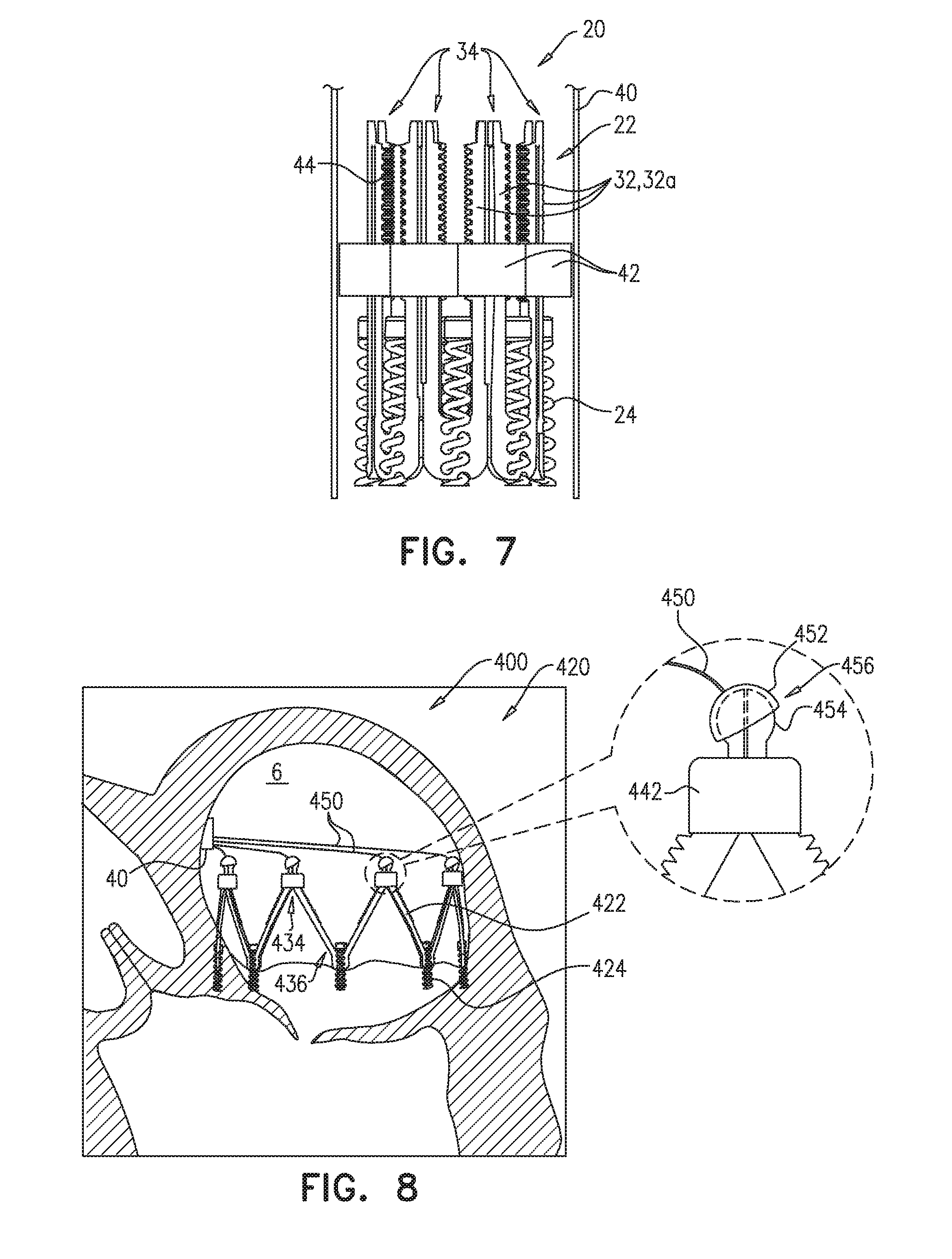
FIG. 7 is a schematic illustration of an implant in its compressed state, in accordance with some applications of the invention;
FIG. 8 is a schematic illustration of a system that comprises an implant, in accordance with some applications of the invention; and
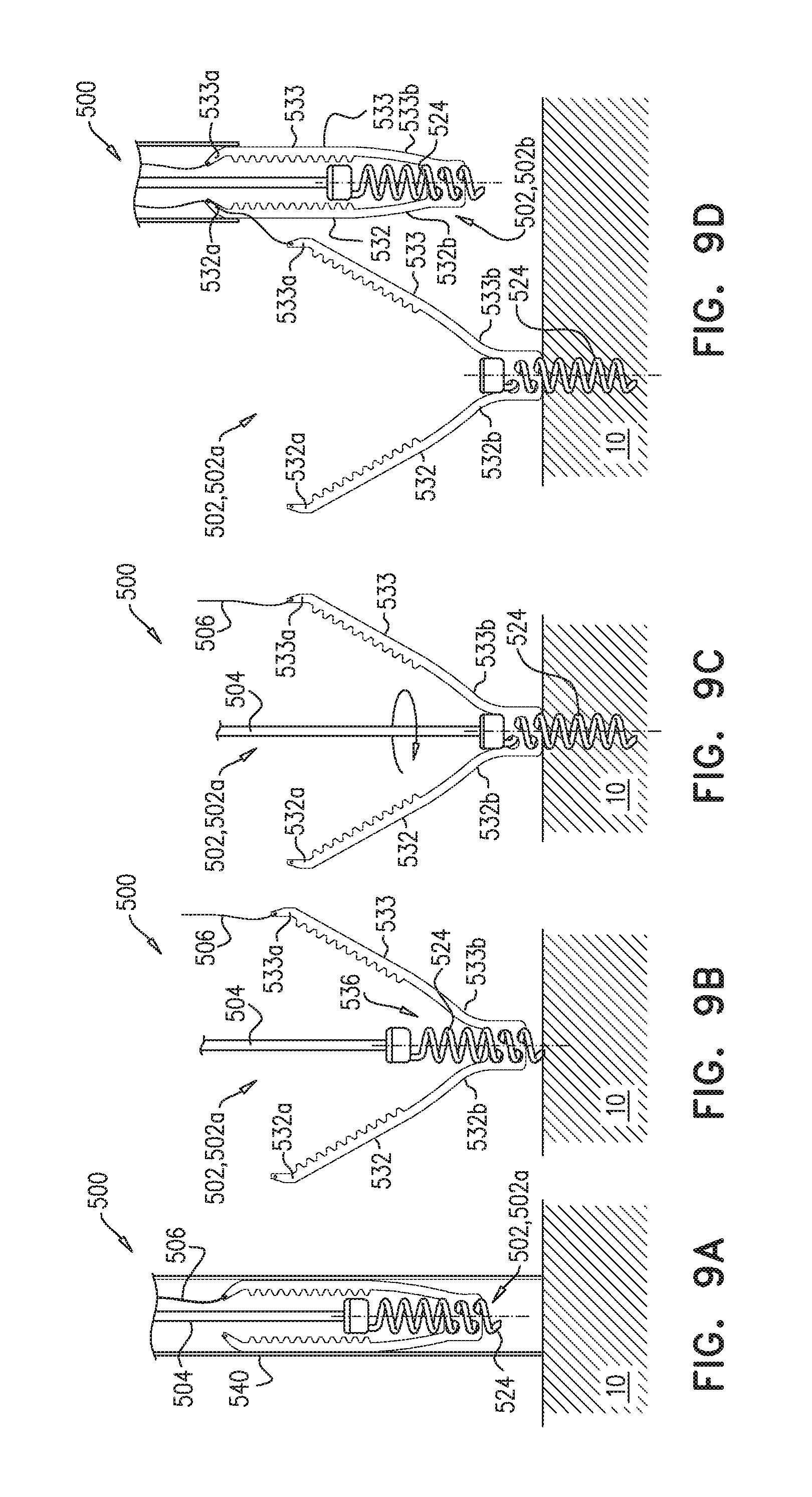
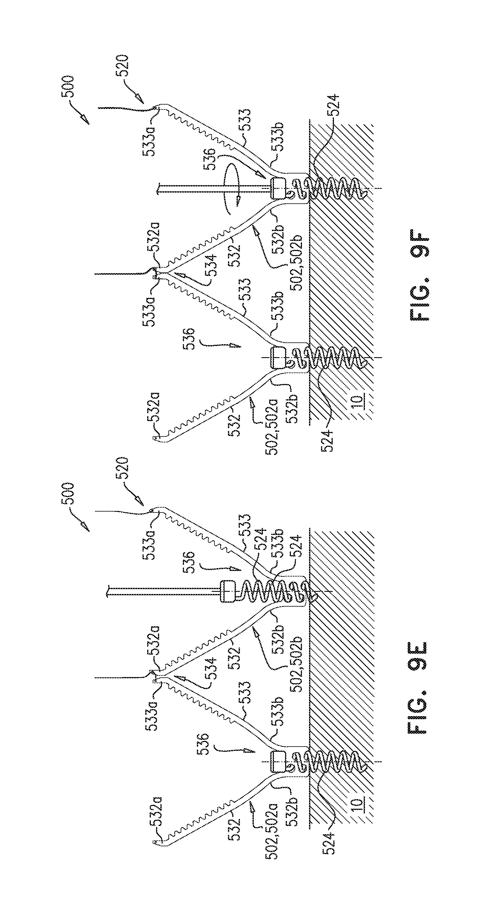
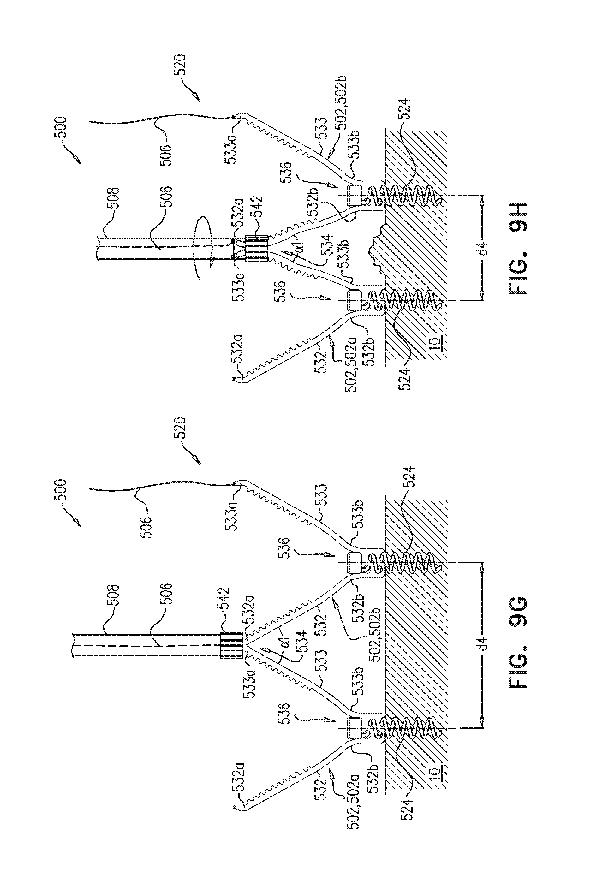
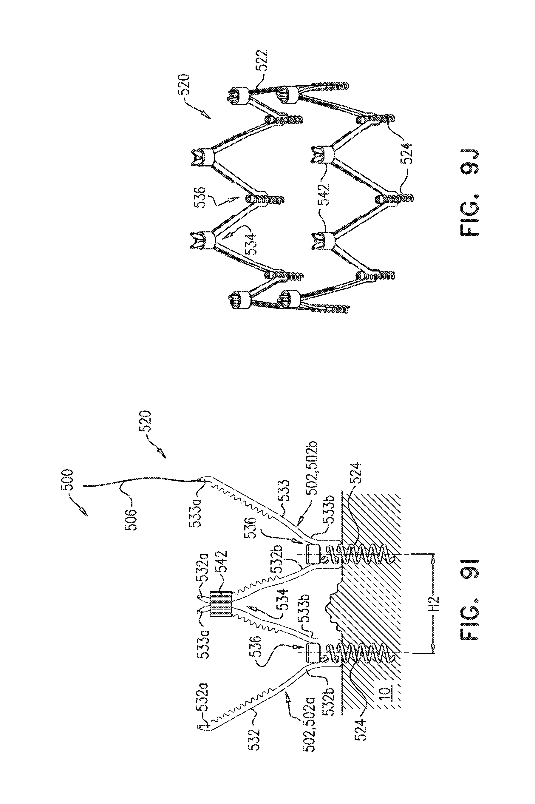
FIGS. 9A-J are schematic illustrations of a system that comprises a plurality of subunits that are intracorporeally assembled to form an implant, in accordance with some applications of the invention.
DETAILED DESCRIPTION OF EMBODIMENTS
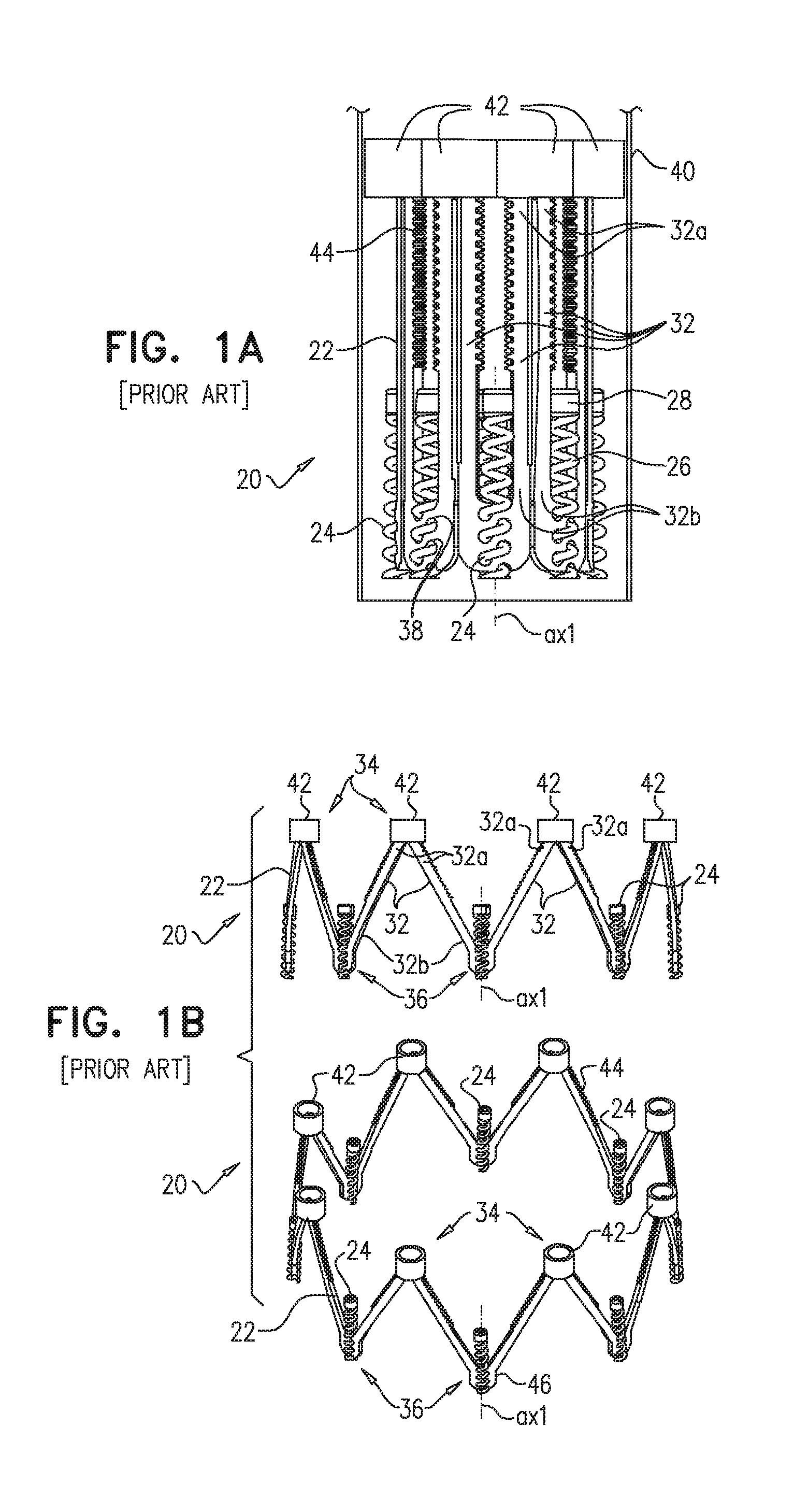
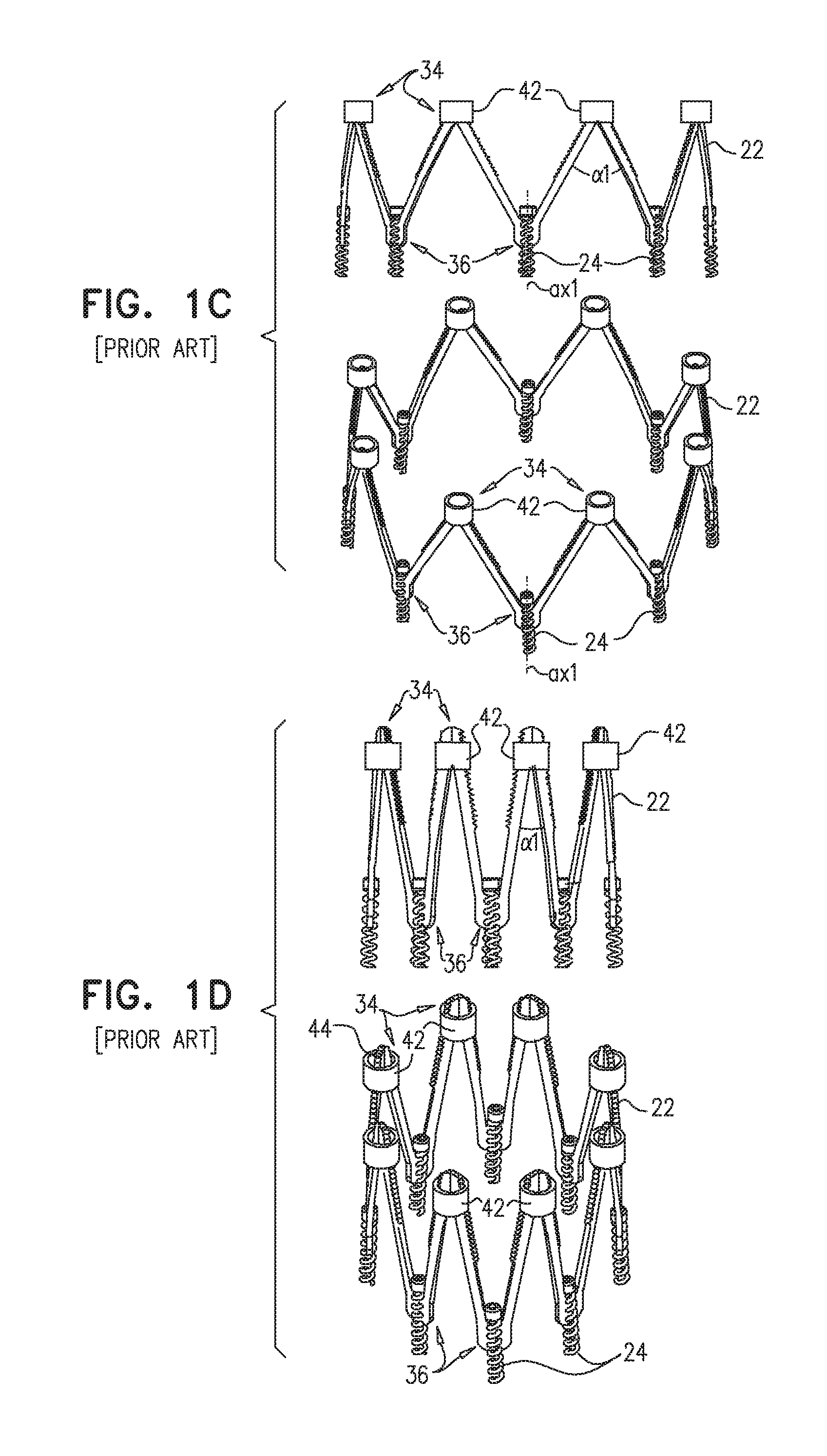
Reference is made to FIGS. 1A-D, which are schematic illustrations of a prior art implant 20 shown in U.S. Pat. No. 9,180,005, for use at a valve (e.g., a mitral valve) of a heart of a subject, in accordance with some applications of the invention. Implant 20 comprises a ring 22 and a plurality of (e.g., 8) anchors 24. Ring comprises a plurality of struts 32 arranged in a pattern of alternating peaks 34 and troughs 36 (e.g., in a zig-zag pattern). Each strut 32 has a first end-portion 32a and a second end-portion 32b. Each peak 34 is defined by convergence of adjacent first end-portions 32a (i.e., of first end-portions 32a of adjacent struts 32), and each trough 36 is defined by convergence of adjacent second end-portions 32b (i.e., of second end-portions 32b of adjacent struts 32).
Each anchor 24 has a longitudinal axis ax1 along which it is configured to be driven into tissue of the annulus of the valve of the heart of the subject, and is coupled to ring 22 at a respective trough 36 in a manner that facilitates movement of the anchor along the longitudinal axis with respect to the trough. At each trough 36, ring 22 defines a plurality of holes 38 through which anchor 24 is moveable. Each anchor 24 comprises a helical tissue-engaging element 26, and an anchor head 28, and is shaped and rotatably coupled to ring 22 at the respective trough 36 such that rotation of the anchor with respect to the ring moves the anchor along its longitudinal axis with respect to the trough (e.g., corkscrews the anchor through holes 38 such that the anchor moves longitudinally). This is illustrated by FIGS. 1B-C, which show anchors 24 in a retracted position (FIG. 1B), and in an extended position after having moved along axis ax1 with respect to its respective trough 36 (FIG. 1C).
Implant 20 comprises an adjustment element 42 for each pair of adjacent first-end portions 32a. Adjustment element 42 is typically an internally-threaded nut that screws onto an external thread 44 (visible in FIG. 1D) defined by the adjacent first-end portions 32a. Such adjustment elements are actuated by rotation (e.g., using an adjustment tool, not shown), and as the adjustment elements are screwed further onto and over struts 32, the angle alpha_1 at which first end-portions 32a converge becomes smaller.
Implant 20 is an annuloplasty device, and is delivered to the heart percutaneously while in a compressed state, via a catheter 40 (FIG. 1A). Within the heart (e.g., within an atrium, such as the left atrium) implant 20 is deployed from the catheter, and automatically expands into an expanded state (FIG. 1B). While in its expanded state, implant 20 is anchored to tissue of the annulus of the valve by driving the anchors along axis ax1 and into the tissue (FIG. 1C). Typically, implant 20 is positioned such that ring 22 surrounds the orifice of the valve. Once implant 20 is anchored, it is contracted by actuating adjustment elements 42, such that angle alpha_1 is reduced (compare FIG. 1C to FIG. 1D). Contraction of implant 20 reduces (i) the circumference and the diameter of ring 22, (ii) the distance between adjacent and opposite anchors 24, and thereby (iii) the circumference and the diameter of the valve of the heart, thereby improving function of the valve.
Reference is now made to FIGS. 2A-B, 3A-B, and 4, which are schematic illustrations of respective implants for use at a valve of a heart of a subject, in accordance with some applications of the invention. FIGS. 2A-B show an implant 120, FIGS. 3A-B show an implant 220, and FIG. 4 shows an implant 320. Unless noted, the structure, function, and use of implants 120, 220, and 320 are similar to those of implant 20. Unless noted, the components of implants 120, 220 and 320 generally correspond to identically-named components of implant 20, mutatis mutandis. The reference numerals assigned to the components of implants 120, 220 and 320 are intended to further illustrate this relationship. For example, struts 132 of implant 120 generally correspond to struts 32 of implant 20, mutatis mutandis (as do struts 232 of implant 220, and struts 332 of implant 320). Implants 120, 220, and 320 are typically delivered transluminally (e.g., transfemorally).
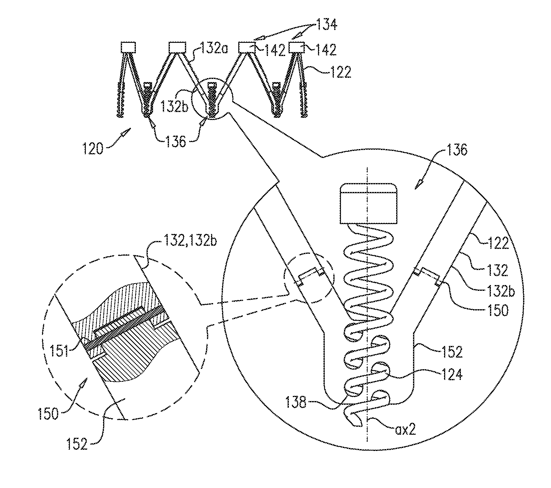
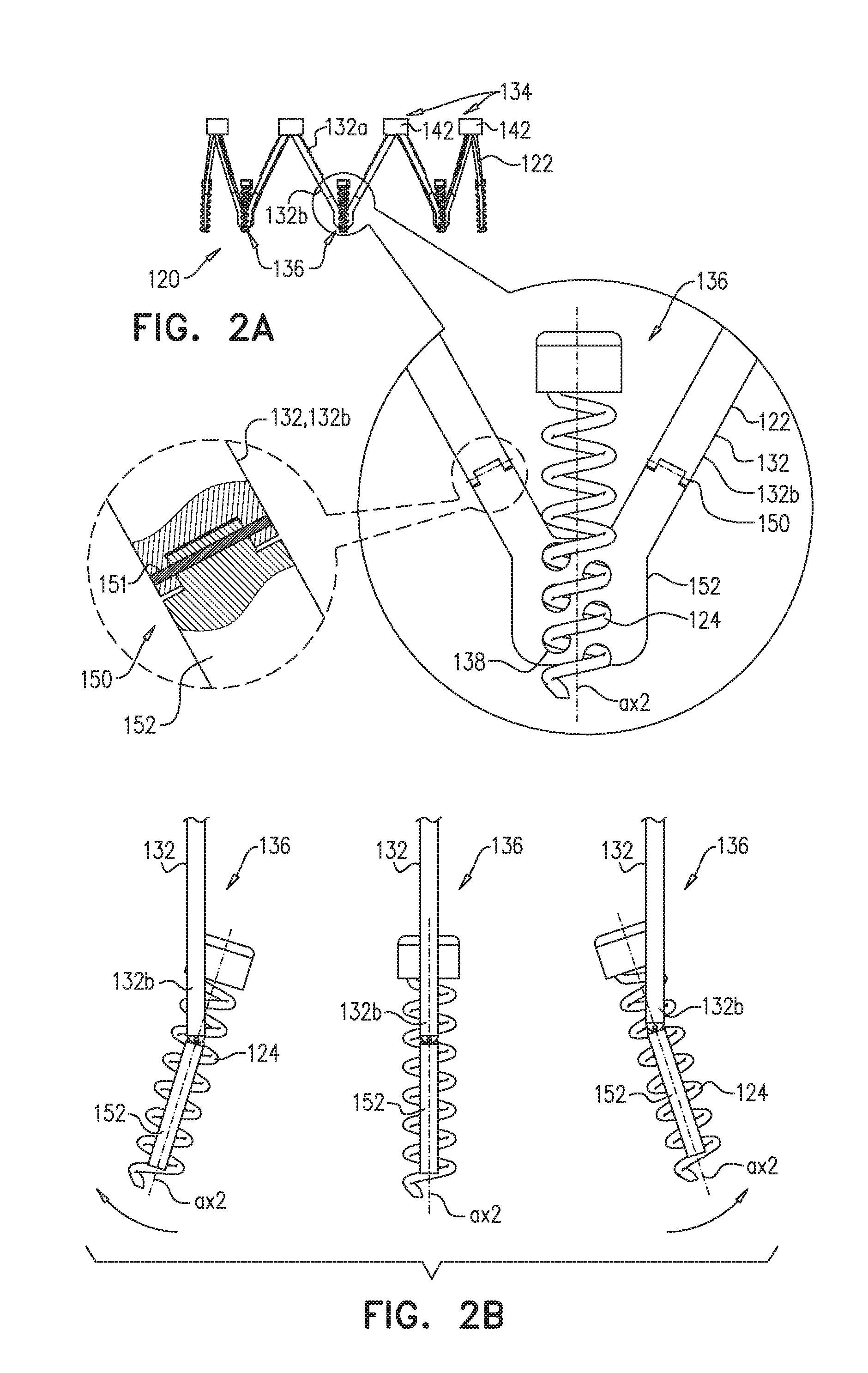
Implant 120 (FIGS. 2A-B) comprises a ring 122 and a plurality of anchors 124. Ring 122 comprises a plurality of struts 132 arranged in a pattern of alternating peaks 134 and troughs 136 (e.g., in a zig-zag pattern). Each strut 132 has a first end-portion 132a and a second end-portion 132b. Each peak 134 is defined by convergence of adjacent first end-portions 132a (i.e., of first end-portions 132a of adjacent struts 132), and each trough 136 is defined by convergence of adjacent second end-portions 132b (i.e., of second end-portions 132b of adjacent struts 132). Similarly to implant 20, implant 120 comprises an adjustment element 142 for each pair of adjacent first-end portions 132a.
Each anchor 124 has a longitudinal axis ax2 along which it is configured to be driven into tissue of the annulus of the valve of the heart of the subject, and is coupled to ring 122 at a respective trough 136 in a manner that facilitates movement of the anchor along the longitudinal axis with respect to the trough. At each trough 136, ring 122 defines a plurality of holes 138 through which anchor 124 is moveable. Typically, each anchor 124 comprises a helical tissue-engaging element and an anchor head (e.g., as described for anchor 24) and is shaped and rotatably coupled to ring 122 at the respective trough 136 such that rotation of the anchor with respect to the ring moves the anchor along its longitudinal axis with respect to the trough (e.g., corkscrews the anchor through holes 138 such that the anchor moves longitudinally).
In contrast to anchors 24 of implant 20, anchors 124 of implant 120 are coupled to ring 122 at respective troughs 136 in a manner that facilitates both (i) movement of the anchor along axis ax2 with respect to the trough, and (ii) deflection of axis ax2 with respect to the trough. That is, as well as moving axially, each anchor 124 can deflect with respect to ring 122 (e.g., with respect to struts 132 thereof). It is hypothesized by the inventors that this facilitates anchoring of implant 120 to the annulus, e.g., by allowing independent orientation of each anchor according to the tissue to which it is to be anchored.
Typically, and as shown, implant 120 (e.g., ring 122 thereof) comprises a plurality of hinges 150, at least one of which is disposed at each trough 136, and the anchor 124 disposed at that trough is coupled to ring 122 via the hinge. Hinge 150 may be a barrel hinge (e.g., comprising a pin 151, as shown), a flexure bearing, or any other suitable hinge type. For some applications, and as shown, the at least one hinge 150 of each trough 136 couples, to each other, the adjacent second end-portions 132b that define that trough. Alternatively, the adjacent second end-portions 132b may be coupled independently of the at least one hinge 150, and the at least one hinge couples anchor 124 to the trough independently of the coupling between the adjacent second end-portions (embodiment not shown).
For some applications, and as shown, implant 120 (e.g., ring 122 thereof) comprises, at each trough 136, an anchor mount 152 that is articulatably coupled to struts 132 (e.g., to second end-portions 132b), e.g., via the at least one hinge 150. Typically, each anchor mount 152 is coupled to one second end-portion 132b via one hinge 150, and to another second end-portion 132b via another hinge. Anchor mount 152 defines the holes 138 of implant 120.
FIG. 2A shows implant 120, with a magnification of a trough 136, and a further magnification of a hinge 150. FIG. 2B illustrates the articulation, at a trough 136, between ring 122 and an anchor 124 (e.g., via the articulated coupling between an anchor mount 152 and struts 132).
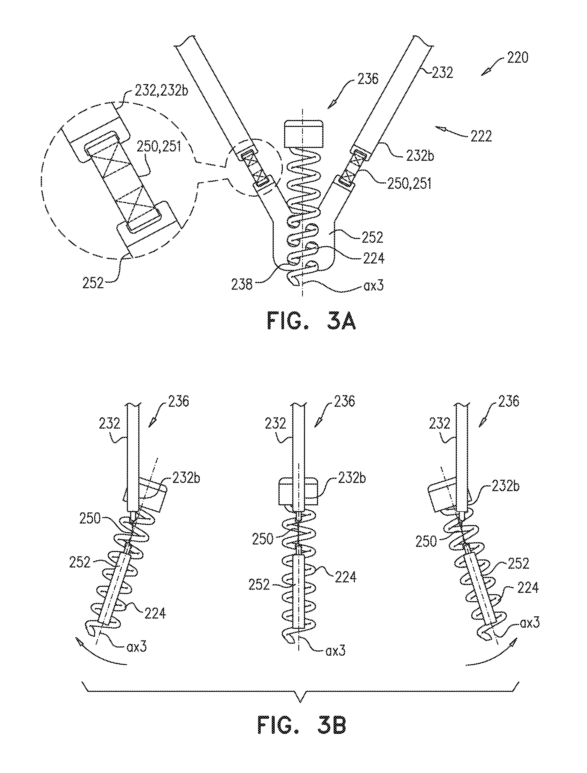
Implant 220 (FIGS. 3A-B) comprises a ring 222 and a plurality of anchors 224. Similar to rings 22 and 122, ring 222 comprises a plurality of struts 232 arranged in a pattern of alternating peaks (not shown) and troughs 236 (e.g., in a zig-zag pattern). Each strut 232 has a first end-portion (not shown) and a second end-portion 232b. Each peak is defined by convergence of adjacent first end-portions (i.e., of first end-portions of adjacent struts 232), and each trough 236 is defined by convergence of adjacent second end-portions 232b (i.e., of second end-portions 232b of adjacent struts 232). Similarly to implants 20 and 120, implant 220 comprises an adjustment element (not shown) for each pair of adjacent first-end portions.
Each anchor 224 has a longitudinal axis ax3 along which it is configured to be driven into tissue of the annulus of the valve of the heart of the subject, and is coupled to ring 222 at a respective trough 236 in a manner that facilitates movement of the anchor along the longitudinal axis with respect to the trough. At each trough 236, ring 222 defines a plurality of holes 238 through which anchor 224 is moveable. Typically, each anchor 224 comprises a helical tissue-engaging element and an anchor head (e.g., as described for anchor 24) and is shaped and rotatably coupled to ring 222 at the respective trough 236 such that rotation of the anchor with respect to the ring moves the anchor along its longitudinal axis with respect to the trough (e.g., corkscrews the anchor through holes 238 such that the anchor moves longitudinally).
In contrast to anchors 24 of implant 20, and similarly to anchors 124 of implant 120, anchors 224 of implant 220 are coupled to ring 222 at respective troughs 236 in a manner that facilitates both (i) movement of the anchor along axis ax3 with respect to the trough, and (ii) deflection of axis ax3 with respect to the trough. That is, as well as moving axially, each anchor 224 can deflect with respect to ring 222 (e.g., with respect to struts 232 thereof). It is hypothesized by the inventors that this facilitates anchoring of implant 220 to the annulus, e.g., by allowing independent orientation of each anchor according to the tissue to which it is to be anchored.
Typically, and as shown, implant 220 (e.g., ring 222 thereof) comprises a plurality of hinges 250, at least one of which is disposed at each trough 236, and the anchor 224 disposed at that trough is coupled to ring 222 via the hinge. Hinge 250 comprises a flexible strip 251, such as a strip of fabric. It is to be noted that although this element is named a "strip," and is shown having a width that is greater than its thickness, and a length that is greater than its width, the term "strip" (including the specification and the claims) is not intended to limit this element to such dimensions. For some applications, and as shown, the at least one hinge 250 of each trough 236 couples, to each other, the adjacent second end-portions 232b that define that trough. Alternatively, the adjacent second end-portions 232b may be coupled independently of the at least one hinge 250, and the at least one hinge couples anchor 224 to the trough independently of the coupling between the adjacent second end-portions (embodiment not shown).
For some applications, and as shown, implant 220 (e.g., ring 222 thereof) comprises, at each trough 236, an anchor mount 252 that is articulatably coupled to struts 232 (e.g., to second end-portions 232b), e.g., via the at least one hinge 250. Typically, each anchor mount 252 is coupled to one second end-portion 232b via one hinge 250, and to another second end-portion 232b via another hinge. Anchor mount 252 defines the holes 238 of implant 220.
For some applications, hinge 250 provides a further degree of movement compared to hinge 150 of implant 120. For example, due to the flexibility of the flexible strip, anchor mount 252 may be twisted and/or deflected asymmetrically with respect to struts 232.
FIG. 3A shows a magnification of a trough 236 of implant 220 (implant 220 is not shown in its entirety), and a further magnification of a hinge 250. FIG. 3B illustrates articulation, at a trough 236, between ring 222 and an anchor 224 (e.g., via the coupling between an anchor mount 252 and struts 232).
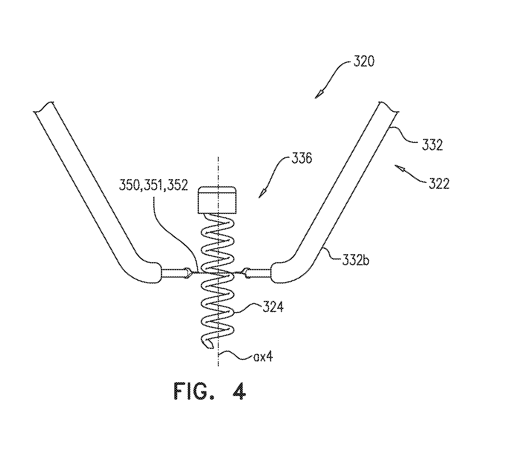
Implant 320 (FIG. 4) comprises a ring 322 and a plurality of anchors 324. Similar to rings 22, 122, and 222, ring 322 comprises a plurality of struts 332 arranged in a pattern of alternating peaks (not shown) and troughs 336 (e.g., in a zig-zag pattern). Each strut 332 has a first end-portion (not shown) and a second end-portion 332b. Each peak is defined by convergence of adjacent first end-portions (i.e., of first end-portions of adjacent struts 332), and each trough 336 is defined by convergence of adjacent second end-portions 332b (i.e., of second end-portions 332b of adjacent struts 332). Similarly to implants 20, 120, and 220, implant 320 comprises an adjustment element (not shown) for each pair of adjacent first-end portions.
Each anchor 324 has a longitudinal axis ax4 along which it is configured to be driven into tissue of the annulus of the valve of the heart of the subject, and is coupled to ring 322 at a respective trough 336 in a manner that facilitates movement of the anchor along the longitudinal axis with respect to the trough. At each trough 336, ring 322 defines at least one hole through which anchor 324 is moveable. Typically, each anchor 324 comprises a helical tissue-engaging element and an anchor head (e.g., as described for anchor 24) and is shaped and rotatably coupled to ring 322 at the respective trough 336 such that rotation of the anchor with respect to the ring moves the anchor along its longitudinal axis with respect to the trough (e.g., corkscrews the anchor through the hole such that the anchor moves longitudinally).
In contrast to anchors 24 of implant 20, and similarly to anchors 124 of implant 120 and anchors 224 of implant 220, anchors 324 of implant 320 are coupled to ring 322 at respective troughs 336 in a manner that facilitates both (i) movement of the anchor along axis ax4 with respect to the trough, and (ii) deflection of axis ax4 with respect to the trough. That is, as well as moving axially, each anchor 324 can deflect with respect to ring 322 (e.g., with respect to struts 332 thereof). It is hypothesized by the inventors that this facilitates anchoring of implant 320 to the annulus, e.g., by allowing independent orientation of each anchor according to the tissue to which it is to be anchored.
Typically, and as shown, implant 320 (e.g., ring 322 thereof) comprises a plurality of hinges 350, each hinge disposed at a respective trough 336, and the anchor 324 disposed at that trough is coupled to ring 322 via the hinge. Hinge 350 comprises a flexible strip 351, such as a strip of fabric. For some applications, and as shown, the hinge 350 of each trough 336 couples, to each other, the adjacent second end-portions 332b that define that trough. Alternatively, the adjacent second end-portions 332b may be coupled independently of the at least one hinge 350, and the at least one hinge couples anchor 324 to the trough independently of the coupling between the adjacent second end-portions (embodiment not shown).
In contrast to implant 220, implant 320 (e.g., ring 322 thereof) typically does not comprise distinct anchor mount. Rather, anchor 324 passes directly through flexible strip 351, and the flexible strip serves as an anchor mount 352, as well as providing the articulation functionality of hinge 350. Strip 351 thereby defines the hole of each trough 336 of implant 320.
For some applications, hinge 350 provides a further degree of movement compared to hinge 150 of implant 120. For example, due to the flexibility of the flexible sheet or strip, anchor 324 may be twisted and/or deflected asymmetrically with respect to struts 332.
FIG. 3A shows a magnification of a trough 336 of implant 320 (implant 320 is not shown in its entirety). FIG. 3B illustrates articulation, at a trough 336, between ring 322 and an anchor 324.
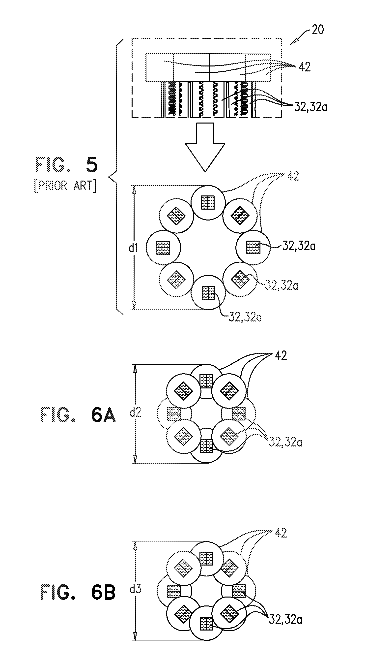
Reference is made to FIGS. 5, and 6A-B, which are schematic illustrations of compressed states of implants, in accordance with some applications of the invention. Implant 20 is used as an example, but the compressed states may apply to the other implants described herein. FIG. 5 shows a partial side view and a top view of implant 20 in its compressed state, e.g., as it would be while disposed within catheter 40, e.g., as shown in FIG. 1A. (The partial side view is taken from U.S. Pat. No. 9,180,005, whereas the top view is based on the inventors' understanding of that reference.) Adjustment elements 42 are disposed at the same longitudinal position on the implant as each other, and because they are wider than the strut-pairs to which they are coupled, they abut each other, and effectively define the widest part of implant 20 in its compressed state. The diameter of implant 20 at this widest part is shown as d1.
FIGS. 6A and 6B show alternative arrangements of adjustment elements 42 in alternative compressed states of implant 20. FIG. 6A shows adjustment elements 42 arranged in an alternating up-down pattern, and FIG. 6B shows the adjustment elements arranged in two sets of four steps. Both of these arrangements allow better compression of implant 20, such that the implant has a diameter d2 or d3 that is smaller than diameter d1. It is to be noted that diameters d2 and d3 are typically smaller than the diameter of a circle formed when all the adjustment elements 42 are arranged in a circle, touching each other.
Reference is made to FIG. 7, which is a schematic illustration of an implant in its compressed state, in accordance with some applications of the invention. Implant 20 is used as an example, but the compressed state may apply to the other implants described herein. As described hereinabove, in a prior art technique, when implant 20 is deployed from catheter 40, it automatically expands into an expanded state. For such a technique, adjustment elements 42 are positioned such that they allow maximal or near-maximal expansion of ring 22 upon deployment of implant 20--e.g., at or close to peaks 34, and/or at or close to an upstream end of threads 44. In the technique of FIG. 7, adjustment elements 42 are positioned such that the restrict expansion of ring 22 upon deployment of implant 20--e.g., closer toward (e.g., at or close to) the downstream end of threads 44. Thus, upon deployment of implant 20 from catheter 40, the implant doesn't automatically expand (or at least not fully). The operator may then expand implant 20 in a controlled and/or stepwise manner by actuating adjusting elements 42 (e.g., such that they move toward peaks 34).
Reference is made to FIG. 8, which is a schematic illustration of a system 400, which comprises an implant 420, in accordance with some applications of the invention. Implant 420 comprises a ring 422 and a plurality of anchors 424. Ring 422 comprises a plurality of struts arranged in a pattern of alternating peaks 434 and troughs 436, e.g., as described herein for other implants. Similarly to other implants described herein, implant 420 comprises an adjustment element 442 for each pair of adjacent struts, e.g., disposed close to (e.g., at) each peak 434. In order to actuate (e.g., rotate) adjustment element 442, an adjustment tool is typically advanced through catheter 40 to the adjustment element. To facilitate guidance of the adjustment tool to the adjustment element, system 400 comprises a plurality of elongate guide members 450 (e.g., one for each adjustment element 442), coupled to ring 422 close to (e.g., at) each peak 434, and extending proximally into catheter 40. The adjustment tool is advanced along the elongate guide member 450 to the adjustment element 442.
Implant 420 (and the other implants described herein, including implant 20) are typically taller than annuloplasty rings known in the art, and therefore peaks 434 and adjustment elements 442 are relatively high within atrium 6. For example, peaks 434 may be only a little inferior to, at the same height as, or even superior to the site at which catheter 40 enters atrium 6 (e.g., the fossa ovalis). Each guide member 450 is coupled to ring 422 (e.g., at a respective peak 434) via a bearing 456. For example, and as shown, bearing 456 may be a ball-and-socket bearing comprising a ball 454 (e.g., defined by implant 420) and a socket 452 (e.g., coupled to, or defined by, a distal end of the guide member 450). Bearing 456 facilitates articulation between the distal end of guide member 450 and implant 420, thereby allowing adjustment elements 442 to be positioned high within atrium 6, while coupled to the guide members.
Reference is made to FIGS. 9A-J, which are schematic illustrations of a system 500, which comprises a plurality of subunits 502 that are intracorporeally assembled to form an implant 520, in accordance with some applications of the invention. Once assembled, implant 520 is similar to implant 20 and/or to another of the implants described herein, mutatis mutandis. System 500 facilitates transfemoral delivery of such an implant, by providing the implant as subunits 502, which individually have a smaller profile than that of a similar implant that is delivered pre-assembled. Thus system 500 may be considered to be a modification of any of the implants described herein, and FIGS. 9A-J may be considered to illustrate a technique for delivering such a modified implant.
Each subunit 502 comprises a pair of struts that comprises a first strut 532 (which has a first end-portion 532a and a second end-portion 532b) and a second strut 533 (which has a first end-portion 533a and a second end-portion 533b). Each subunit defines a trough 536 at which the second end-portion of each strut of the pair is coupled to the second end-portion of the other strut of the pair (i.e., end-portion 532b is coupled to end-portion 533b).
A first subunit 502a is transfemorally delivered to the native heart valve (e.g., in a compressed state, within a catheter 540), typically into an atrium such as the left atrium 6 of the heart (FIG. 9A). Subsequently, the trough 536 of subunit 502a is anchored to tissue 10 that surrounds the valve (e.g., tissue of the valve annulus) by driving a tissue anchor 524 into the tissue, such as by using an anchor driver tool 504, which may be used to facilitate deployment of the subunit out of catheter 540 (FIGS. 9B-C).
Subsequently, first end-portion 533a of second strut 533 of subunit 502a is secured to first end-portion 532a of first strut 532 of another subunit 502b, such that the secured first end-portions converge at an angle alpha_1 to define a peak 534 (FIGS. 9D-G). For example, and as shown, end-portion 533a of first subunit 502a may have an elongate guide member 506 attached thereto, the guide member extending proximally from end-portion 533a of the implanted subunit (e.g., into a delivery sheath, such as to outside of the subject), and end-portion 532a of subunit 502b is advanced over and along the guide member, guided by the guide member to end-portion 533a of subunit 502a. Subunit 502b is anchored to tissue 10 in the same way as subunit 502a.
Typically, an adjustment element 542 is subsequently coupled to the first end-portions that define each peak (FIG. 9G). For some applications, this further secures these two end-portions to each other. For example, for applications in which adjustment element 542 comprises a nut (e.g., as described hereinabove, mutatis mutandis), the nut is typically screwed onto the threads defined by the end-portions (e.g., using a tool 508 that is reversibly coupled to the adjustment element, and is slidable over and along guide member 506), thereby securing the end-portions to each other.
Subsequently to the steps of anchoring and securing, the angle alpha_1 defined by each peak 534 is reduced by actuating the adjustment element 542 of that peak, e.g., using tool 508. This reduces a distance d4 between anchors 524 of the adjacent subunits, thereby reducing the circumference of a portion of the annulus of the valve being treated. The adjustment is shown in FIG. 9H in order to illustrate that the adjustment of each adjustment element 542 may be performed after each subunit 502 is secured. Alternatively, the adjustment may be deferred until after more than one (e.g., all) of the subunits have been secured (e.g., similarly to implant 20).
Following implantation, guide member 506 is typically decoupled from implant 520 and removed from the subject (FIG. 9I). This may be achieved by unthreading and/or cutting each guide member 506 (e.g., facilitated by tool 508), or by any other suitable technique known in the art.
The above process is repeated iteratively, mutatis mutandis, until implant 520 has been fully assembled, e.g., formed into a full ring such as that of implant 20, or into a partial ring or band (FIG. 9J).
The techniques described with reference to FIGS. 9A-J may be used to assemble implants similar to implants 20, 120, 220 and 320, mutatis mutandis.
It will be appreciated by persons skilled in the art that the present invention is not limited to what has been particularly shown and described hereinabove. Rather, the scope of the present invention includes both combinations and subcombinations of the various features described hereinabove, as well as variations and modifications thereof that are not in the prior art, which would occur to persons skilled in the art upon reading the foregoing description.
* * * * *
D00000
D00001
D00002
D00003
D00004
D00005
D00006
D00007
D00008
D00009
D00010
D00011
XML
uspto.report is an independent third-party trademark research tool that is not affiliated, endorsed, or sponsored by the United States Patent and Trademark Office (USPTO) or any other governmental organization. The information provided by uspto.report is based on publicly available data at the time of writing and is intended for informational purposes only.
While we strive to provide accurate and up-to-date information, we do not guarantee the accuracy, completeness, reliability, or suitability of the information displayed on this site. The use of this site is at your own risk. Any reliance you place on such information is therefore strictly at your own risk.
All official trademark data, including owner information, should be verified by visiting the official USPTO website at www.uspto.gov. This site is not intended to replace professional legal advice and should not be used as a substitute for consulting with a legal professional who is knowledgeable about trademark law.