Lower body mimetic exercise device with fully or partially autonomous right and left leg links and ergonomically positioned pivot points
Luger , et al.
U.S. patent number 10,220,250 [Application Number 15/155,168] was granted by the patent office on 2019-03-05 for lower body mimetic exercise device with fully or partially autonomous right and left leg links and ergonomically positioned pivot points. This patent grant is currently assigned to Octane Fitness, LLC. The grantee listed for this patent is Octane Fitness, LLC. Invention is credited to Daniel C. Boyles, Thomas C. Coy, Nathan R. Luger, Mark R. Nestande, Charles J. Rosenow.


View All Diagrams
| United States Patent | 10,220,250 |
| Luger , et al. | March 5, 2019 |
Lower body mimetic exercise device with fully or partially autonomous right and left leg links and ergonomically positioned pivot points
Abstract
An exercise device having (-) a frame, (-) left and right leg linkages, each including (i) an upper leg member pivotally coupled to the frame for pivoting about an upper pivot point with the upper pivot point of each leg linkage defining a point on a laterally extending upper pivot axis that passes through the upper pivot point of each leg linkage, and (ii) a lower leg member directly pivotally coupled to the upper leg member distal to the upper pivot point for pivoting about a lower pivot point, and (-) a foot support attached to each lower leg member distal to each respective lower pivot point. The invention characterized by an ergonomically synergistic spatial orientation and relationship amongst and between the upper leg members, lower leg members, upper pivot axis, lower pivot axis, hip region of a user, knees of a user, a biased damping means in communication with the lower leg members, and an interconnect member interconnecting the lower leg links with and the biased damping means.
| Inventors: | Luger; Nathan R. (Roseville, MN), Coy; Thomas C. (Saint Michael, MN), Nestande; Mark R. (Chaska, MN), Boyles; Daniel C. (Ramsey, MN), Rosenow; Charles J. (Ramsey, MN) | ||||||||||
|---|---|---|---|---|---|---|---|---|---|---|---|
| Applicant: |
|
||||||||||
| Assignee: | Octane Fitness, LLC (Brooklyn
Park, MN) |
||||||||||
| Family ID: | 51399548 | ||||||||||
| Appl. No.: | 15/155,168 | ||||||||||
| Filed: | May 16, 2016 |
Prior Publication Data
| Document Identifier | Publication Date | |
|---|---|---|
| US 20160256735 A1 | Sep 8, 2016 | |
Related U.S. Patent Documents
| Application Number | Filing Date | Patent Number | Issue Date | ||
|---|---|---|---|---|---|
| 14468780 | Aug 26, 2014 | 9364708 | |||
| 61871710 | Aug 29, 2013 | ||||
| Current U.S. Class: | 1/1 |
| Current CPC Class: | A63B 22/0664 (20130101); A63B 22/001 (20130101); A63B 21/0442 (20130101); A63B 22/04 (20130101); A63B 23/0429 (20130101); A63B 23/1209 (20130101); A63B 21/0552 (20130101); A63B 21/0083 (20130101); A63B 22/0056 (20130101); A63B 22/0012 (20130101); A63B 23/03541 (20130101); A63B 2208/0204 (20130101); A63B 2022/0038 (20130101); A63B 21/0726 (20130101); A63B 71/0036 (20130101); A63B 21/075 (20130101); A63B 2022/0682 (20130101); A63B 2022/0051 (20130101) |
| Current International Class: | A63B 21/008 (20060101); A63B 22/06 (20060101); A63B 23/035 (20060101); A63B 23/04 (20060101); A63B 71/00 (20060101); A63B 23/12 (20060101); A63B 21/04 (20060101); A63B 22/00 (20060101); A63B 22/04 (20060101); A63B 21/055 (20060101); A63B 21/075 (20060101); A63B 21/072 (20060101) |
References Cited [Referenced By]
U.S. Patent Documents
| 219439 | September 1879 | Blend |
| 2919494 | January 1960 | Runci |
| 3316898 | May 1967 | Brown |
| 3316899 | May 1967 | Raeder |
| 3970302 | July 1976 | McFee |
| 3995491 | December 1976 | Wolfla, II |
| 4023795 | May 1977 | Pauls |
| 4053173 | October 1977 | Chase, Sr. |
| 4185622 | January 1980 | Swenson |
| 4188030 | February 1980 | Hooper |
| 4379566 | April 1983 | Titcomb |
| 4456276 | June 1984 | Bortolin |
| 4456279 | June 1984 | Dirck |
| 4470597 | September 1984 | McFee |
| 4496147 | January 1985 | DeCloux |
| 4509742 | April 1985 | Cones |
| 4555109 | November 1985 | Hartmann |
| 4561318 | December 1985 | Schirrmacher |
| 4679786 | July 1987 | Rodgers |
| 4685666 | August 1987 | DeCloux |
| 4708338 | November 1987 | Potts |
| 4709918 | December 1987 | Grinblat |
| 4720093 | January 1988 | Del Mar |
| 4733858 | March 1988 | Lan |
| 4779863 | October 1988 | Yang |
| 4786050 | November 1988 | Geschwender |
| 4838543 | June 1989 | Armstrong |
| 4850585 | July 1989 | Dalebout |
| 4869494 | September 1989 | Lambert, Sr. |
| 4900013 | February 1990 | Rodgers, Jr. |
| 4940233 | July 1990 | Bull |
| 4949954 | August 1990 | Hix |
| 4949993 | August 1990 | Stark |
| 4951942 | August 1990 | Walden |
| 4989857 | February 1991 | Kuo |
| 5000442 | March 1991 | Dalebout |
| 5000443 | March 1991 | Dalebout |
| 5038758 | August 1991 | Iams |
| 5039087 | August 1991 | Kuo |
| 5039088 | August 1991 | Shifferaw |
| 5040786 | August 1991 | Jou |
| 5048821 | September 1991 | Kuo-Liang |
| 5062627 | November 1991 | Bingham |
| 5072928 | December 1991 | Stearns |
| 5129872 | July 1992 | Dalton |
| 5131895 | July 1992 | Rogers, Jr. |
| 5135447 | August 1992 | Robards, Jr. |
| 5149312 | September 1992 | Croft |
| 5186697 | February 1993 | Rennex |
| 5195935 | March 1993 | Fencel |
| 5242343 | September 1993 | Miller |
| 5279529 | January 1994 | Eschenbach |
| 5279530 | January 1994 | Hess |
| 5290211 | March 1994 | Stearns |
| 5295928 | March 1994 | Rennex |
| 5299993 | April 1994 | Habing |
| 5336141 | August 1994 | Vittone |
| 5352169 | October 1994 | Eschenbach |
| 5383829 | January 1995 | Miller |
| 5401226 | March 1995 | Stearns |
| 5419747 | May 1995 | Piaget |
| 5423729 | June 1995 | Eschenbach |
| 5496235 | March 1996 | Stevens |
| 5499956 | March 1996 | Habings et al. |
| 5518473 | May 1996 | Miller |
| 5527246 | June 1996 | Rodgers, Jr. |
| 5529554 | June 1996 | Eschenbach |
| 5529555 | June 1996 | Rodgers, Jr. |
| 5538486 | July 1996 | France |
| 5540637 | July 1996 | Rodgers, Jr. |
| 5549526 | August 1996 | Rodgers, Jr. |
| 5573480 | November 1996 | Rodgers, Jr. |
| 5577985 | November 1996 | Miller |
| 5584780 | December 1996 | Lin |
| 5593372 | January 1997 | Rodgers, Jr. |
| 5595553 | January 1997 | Rodgers, Jr. |
| 5611756 | March 1997 | Miller |
| 5637058 | June 1997 | Rogers, Jr. |
| 5735773 | April 1998 | Vittone |
| 5746681 | May 1998 | Bull |
| 5769760 | June 1998 | Lin |
| 5788610 | August 1998 | Eschenbach |
| 5792026 | August 1998 | Maresh |
| 5792027 | August 1998 | Gvoich |
| 5792028 | August 1998 | Jarvie |
| 5792029 | August 1998 | Gordon |
| 5813949 | September 1998 | Rogers, Jr. |
| 5857940 | January 1999 | Husted |
| 5876308 | March 1999 | Jarvie |
| 5910072 | June 1999 | Rawls |
| 5911649 | June 1999 | Miller |
| 5967944 | October 1999 | Vittone |
| 6004244 | December 1999 | Simonson |
| 6036622 | March 2000 | Gordon |
| 6045487 | April 2000 | Miller |
| 6152859 | November 2000 | Stearns |
| 6183397 | February 2001 | Stearns |
| 6368252 | April 2002 | Stearns |
| 6390953 | May 2002 | Maresh |
| D476046 | June 2003 | Wang |
| 7226390 | June 2007 | Stearns |
| 7285075 | October 2007 | Cutler |
| D555743 | November 2007 | Wang |
| 7520839 | April 2009 | Rodgers, Jr. |
| 7530926 | May 2009 | Rodgers, Jr. |
| 7608018 | October 2009 | Chuang |
| 7645215 | January 2010 | Gordon |
| 7678025 | March 2010 | Rodgers, Jr. |
| 7708669 | May 2010 | Rogers, Jr. |
| 7828698 | May 2010 | Rogers, Jr. |
| 7833134 | November 2010 | Gordon |
| 7862482 | January 2011 | Hsu |
| D640337 | June 2011 | Liu |
| 8082029 | December 2011 | Honda |
| 8109861 | February 2012 | Gordon |
| 8409058 | April 2013 | Gordon et al. |
| D703278 | April 2014 | Horita |
| 9050491 | June 2015 | Gordon et al. |
| 2002/0049121 | April 2002 | Anderson |
| 2003/0092532 | May 2003 | Giannelli |
| 2004/0224825 | November 2004 | Giannelli |
| 2005/0054488 | March 2005 | Husted |
| 2006/0189454 | August 2006 | Bull |
| 2008/0132385 | June 2008 | Alessandri |
| 2008/0287265 | November 2008 | Giannelli |
| 2009/0203501 | August 2009 | Rodgers, Jr. |
| 2010/0093498 | April 2010 | Fenster |
| 2010/0160115 | June 2010 | Morris |
| 2010/0267524 | October 2010 | Stewart |
| 2011/0028275 | February 2011 | Stewart |
| 2014/0148311 | May 2014 | Eschenbach |
| 202682672 | Jan 2013 | CN | |||
| 2919494 | Nov 1980 | DE | |||
| 10060466 | Jun 2002 | DE | |||
| 2000178 | Dec 2008 | EP | |||
| 2008124025 | Oct 2008 | WO | |||
Attorney, Agent or Firm: Sherrill Law Office, PLLC
Claims
We claim:
1. An exercise device having (-) a frame with a forward end and a rearward end wherein the frame is configured and arranged to accommodate user access onto the exercise device from the rearward end, (-) left and right leg linkages, each including (i) an upper leg member pivotally coupled to the frame for pivoting about an upper pivot point, with the upper pivot point of each leg linkage defining a point on a laterally extending upper pivot axis that passes through the upper pivot point of each leg linkage, and (ii) a lower leg member directly pivotally coupled to the upper leg member distal to the upper pivot point for pivoting about a lower pivot point, and (-) a foot support attached to each lower leg member distal to each respective lower pivot point, characterized by an ergonomically synergistic combination of: (a) an interconnection of the upper leg members for synchronized out of phase pivoting about each respective upper pivot point, (b) each of the lower leg members being separate and independent for autonomous pivoting of each of the lower leg members relative to each other about each respective lower pivot point, and (c) a joint-pivot spatial correlation selected from at least one of: (i) a location of the upper pivot axis configured to pass through or posterior to the hip region of an orthostatic forward facing suited user supported upon the foot supports with the foot supports horizontally and vertically aligned, and (ii) a location of each of the lower pivot points configured to be respectively proximate to one of the knees of the orthostatic forward facing suited user supported upon the foot supports with the foot supports horizontally and vertically aligned.
2. The exercise device of claim 1 wherein the joint-pivot spatial correlation is a location of the upper pivot axis configured to pass through or posterior to the hip region of the orthostatic forward facing suited user supported upon the foot supports with the foot supports horizontally and vertically aligned.
3. The exercise device of claim 1 wherein the joint-pivot spatial correlation is a location of each of the lower pivot points configured to be respectively proximate to one of the knees of the orthostatic forward facing suited user supported upon the foot supports with the foot supports horizontally and vertically aligned.
4. The exercise device of claim 1 wherein the joint-pivot spatial correlation is both (i) a location of the upper pivot axis configured to pass through or posterior to the hip region of the orthostatic forward facing suited user supported upon the foot supports with the foot supports horizontally and vertically aligned, and (ii) a location of each of the lower pivot points configured to be respectively proximate to one of the knees of the orthostatic forward facing suited user supported upon the foot supports with the foot supports horizontally and vertically aligned.
5. The exercise device of claim 1 wherein each lower leg member communicates with a biased damping means for biased pivoting of each lower leg member about each respective lower pivot point towards a first direction and damped pivoting of each lower leg member about each respective lower pivot point in a second direction opposite the first direction.
6. The exercise device of claim 5 wherein a biasing force exerted by each of the biased damping means is adjustable.
7. The exercise device of claim 5 wherein a damping force exerted by the biased damping means is adjustable.
8. The exercise device of claim 6 wherein a damping force exerted by the biased damping means is adjustable.
9. The exercise device of claim 1 further comprising a control console attached to the frame proximate to the forward end of the frame.
10. The exercise device of claim 1 wherein (i) each upper leg member pivots about the respective upper pivot point and is coupled to the respective lower leg member which pivots about the respective lower pivot point, and (ii) each upper leg member pivots about the respective upper pivot point autonomously relative to pivoting of the respective lower leg member about the respective lower pivot point, whereby (iii) pivoting of each upper leg member about the respective upper pivot point effects pivoting of the respective lower pivot point about the upper pivot point without inducing pivoting of the respective lower leg member about the respective lower pivot point.
11. The exercise device of claim 1 wherein (i) each lower leg member pivots about the respective lower pivot point and is coupled to the respective upper leg member which pivots about the respective upper pivot point, and (ii) each lower leg member pivots about the respective lower pivot point autonomously relative to pivoting of the respective upper leg member about the respective upper pivot point, whereby (iii) pivoting of each lower leg member about the respective lower pivot point does not induce pivoting of the respective upper leg member about the respective upper pivot point.
12. The exercise device of claim 10 wherein each lower leg member pivots about the respective lower pivot point autonomously relative to pivoting of the respective upper leg member about the respective upper pivot point, whereby pivoting of each lower leg member about the respective lower pivot point does not induce pivoting of the respective upper leg member about the respective upper pivot point.
13. An exercise device having (-) a frame with a forward end and a rearward end wherein the frame is configured and arranged to accommodate user access onto the exercise device from the rearward end, (-) left and right leg linkages, each including (i) an upper leg member pivotally coupled to the frame for pivoting about an upper pivot point, with the upper pivot point of each leg linkage defining a point on a laterally extending upper pivot axis that passes through the upper pivot point of each leg linkage, and (ii) a lower leg member directly pivotally coupled to the upper leg member distal to the upper pivot point for pivoting about a lower pivot point, and (-) a foot support attached to each lower leg member distal to each respective lower pivot point, characterized by an ergonomically synergistic combination of: (a) an interconnection of the upper leg members for synchronized out of phase pivoting about each respective upper pivot point, (b) each of the lower leg members being separate and independent for autonomous pivoting of each of the lower leg members relative to each other about each respective lower pivot point, and (c) a biased damping system for effecting biased pivoting of each lower leg member about each respective lower pivot point towards a first direction and damped pivoting of each lower leg member about each respective lower pivot point in a second direction opposite the first direction.
Description
BACKGROUND
The fitness industry has long desired a stationary, low-impact, exercise machine capable of adapting and conforming to a user's natural gait, stride and pace (hereinafter "user conforming exercise machine") during exercise. Treadmills accommodate user-defined gait and stride (i.e., uncontrolled path of travel), but are high-impact with machine-dictated pace. Elliptical exercise machines are low-impact and accommodate user-defined pace, but have machine-dictated gait and stride (i.e., defined path of travel).
Several attempts have been made to achieve a user-conforming exercise machine by employing leg linkages that mimic human legs (i.e., an exercise machine having a stationary frame supporting a pair of leg linkages with each leg linkage having (i) an upper link pivotally coupled proximate its upper end to the frame, (ii) a lower link pivotally coupled proximate its upper end to the lower end of the upper link, and (iii) a foot support on the lower end of each lower link). Exemplary lower body mimetic stationary exercise machines are depicted and described in U.S. Pat. Nos. 5,290,211, 5,499,956, 5,735,773, 5,911,649, 6,036,622, 6,045,487, 6,152,859 (FIG. 29), U.S. Pat. Nos. 7,645,215, 7,833,134, 8,109,861, and 8,409,058, the disclosures of which are hereby incorporated by reference. While constituting a significant advance towards achieving a user-conforming exercise machine, these lower body mimetic stationary exercise machines have met with limited commercial success as they exert active and reactive forces that do not coordinate well with a user's innately anticipated natural interaction with the environment during walking or running.
Accordingly, a need continues to exist for a stationary user-conforming exercise machine that ergonomically conforms to the natural innate striding motion of the user.
SUMMARY OF THE INVENTION
The invention is directed to a variable gait exercise device with fully or partially autonomous right and left leg links and ergonomically positioned hip and/or knee pivot points.
A stationary lower body mimetic exercise machine capable of providing a versatile foot support motion that conforms to the natural, innate and ergonomic striding motion of the user, as opposed to influencing a user into a machine chosen striding motion, can be achieved by providing the machine with left-right autonomous thigh and/or calf links with ergonomically aligned hip and/or calf pivot points, with each combination of autonomy and ergonomic alignment possessing certain unique subtle refinements in interaction between the machine and its human operator.
In a first aspect, the exercise machine is a stationary lower body mimetic exercise machine wherein (i) user orientation on the machine is determined by at least one of (-) configuring the frame to accommodate user access onto the exercise machine from the rearward end of the frame, and (-) providing a display mounted to the frame for displaying information viewable by a forward facing orthostatic user supported upon the foot supports, (ii) the first and second hip pivot points define a laterally extending upper pivot axis, (iii) the left and right leg linkages selectively interact such that at least one of (-) the thigh members pivot autonomously relative to one another about the hip pivot points while the calf members are interconnected for synchronized out of phase pivoting about the knee pivot points, and (-) the calf members pivot autonomously relative to one another about the knee pivot points while the thigh members are interconnected for synchronized out of phase pivoting about the hip pivot points, and (iv) the thigh members, calf members and foot supports are supported, configured and arranged such that the upper pivot axis will pass through or posterior to the hip region of an orthostatic forward facing suited user supported upon the foot supports with the foot supports horizontally and vertically aligned.
In a first embodiment of the first aspect of the invention, the thigh members pivot autonomously relative to one another about the hip pivot points while the calf members are interconnected for synchronized out of phase pivoting about the knee pivot points.
In a second embodiment of the first aspect of the invention, the calf members pivot autonomously relative to one another about the knee pivot points while the thigh members are interconnected for synchronized out of phase pivoting about the hip pivot points.
In a third embodiment of the first aspect of the invention, the left leg linkage and the right leg linkage pivot autonomously relative to one another about both the hip pivot points and the knee pivot points.
In an alternative portrayal, the third embodiment has (i) thigh members that pivot autonomously relative to one another about their respective hip pivot points, and (ii) calf members that pivot autonomously relative to one another about their respective knee pivot points.
In a second aspect, the exercise machine is a stationary lower body mimetic exercise machine wherein (i) user orientation on the machine is determined by at least one of (-) configuring the frame to accommodate user access onto the exercise machine from the rearward end of the frame, and (-) providing a display mounted to the frame for displaying information viewable by a forward facing orthostatic user supported upon the foot supports, (ii) the left and right leg linkages selectively interact such that at least one of (-) the thigh members pivot autonomously relative to one another about the hip pivot points while the calf members are interconnected for synchronized out of phase pivoting about the knee pivot points, and (-) the calf members pivot autonomously relative to one another about the knee pivot points while the thigh members are interconnected for synchronized out of phase pivoting about the hip pivot points, and (iii) the thigh members, calf members and foot supports are supported, configured and arranged such that the first and second lower pivot axis are each positioned proximate one of the knees of an orthostatic forward facing suited user supported upon the foot supports with the foot supports horizontally and vertically aligned.
In a first embodiment of the second aspect of the invention, the thigh members pivot autonomously relative to one another about the hip pivot points while the calf members are interconnected for synchronized out of phase pivoting about the knee pivot points.
In a second embodiment of the second aspect of the invention, the calf members pivot autonomously relative to one another about the knee pivot points while the thigh members are interconnected for synchronized out of phase pivoting about the hip pivot points.
In a third embodiment of the second aspect of the invention, the left leg linkage and the right leg linkage pivot autonomously relative to one another about both the hip pivot points and the knee pivot points.
In an alternative portrayal, the third embodiment has (i) thigh members that pivot autonomously relative to one another about their respective hip pivot points, and (ii) calf members that pivot autonomously relative to one another about their respective knee pivot points.
In a third aspect, the exercise machine is a stationary lower body mimetic exercise machine wherein (i) user orientation on the machine is determined by at least one of (-) configuring the frame to accommodate user access onto the exercise machine from the rearward end of the frame, and (-) providing a display mounted to the frame for displaying information viewable by a forward facing orthostatic user supported upon the foot supports, (ii) the first and second hip pivot points define a laterally extending upper pivot axis, (iii) the left and right leg linkages selectively interact such that at least one of (-) the thigh members pivot autonomously relative to one another about the hip pivot points while the calf members are interconnected for synchronized out of phase pivoting about the knee pivot points, and (-) the calf members pivot autonomously relative to one another about the knee pivot points while the thigh members are interconnected for synchronized out of phase pivoting about the hip pivot points, and (iii) the thigh members, calf members and foot supports are supported, configured and arranged such that the upper pivot axis passes through or posterior to the hip region and the first and second lower pivot axis are each positioned proximate one of the knees, both in relation to an orthostatic forward facing suited user supported upon the foot supports with the foot supports horizontally and vertically aligned.
In a first embodiment of the third aspect of the invention, the thigh members pivot autonomously relative to one another about the hip pivot points while the calf members are interconnected for synchronized out of phase pivoting about the knee pivot points.
In a second embodiment of the third aspect of the invention, the calf members pivot autonomously relative to one another about the knee pivot points while the thigh members are interconnected for synchronized out of phase pivoting about the hip pivot points.
In a third embodiment of the third aspect of the invention, the left leg linkage and the right leg linkage pivot autonomously relative to one another about both the hip pivot points and the knee pivot points.
In an alternative portrayal, the third embodiment has (i) thigh members that pivot autonomously relative to one another about their respective hip pivot points, and (ii) calf members that pivot autonomously relative to one another about their respective knee pivot points.
BRIEF DESCRIPTION OF THE DRAWINGS
Each Figure depicts the components of the invention represented therein in proper proportion to one another. Those Figures which include depiction of a human supported upon the foot supports of the invention depict the machine in proper proportion to the human, who is 6 feet 2 inches tall, has an inseam of 32 inches, weighs 178 pounds, and wears a size 9.5 US shoe.
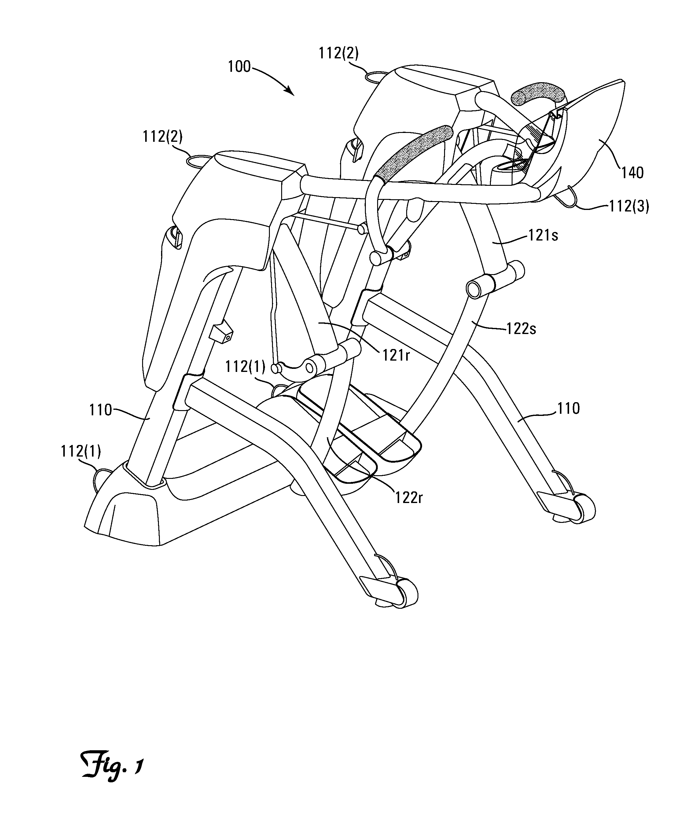
FIG. 1 is a front isometric view of one embodiment of the invention.
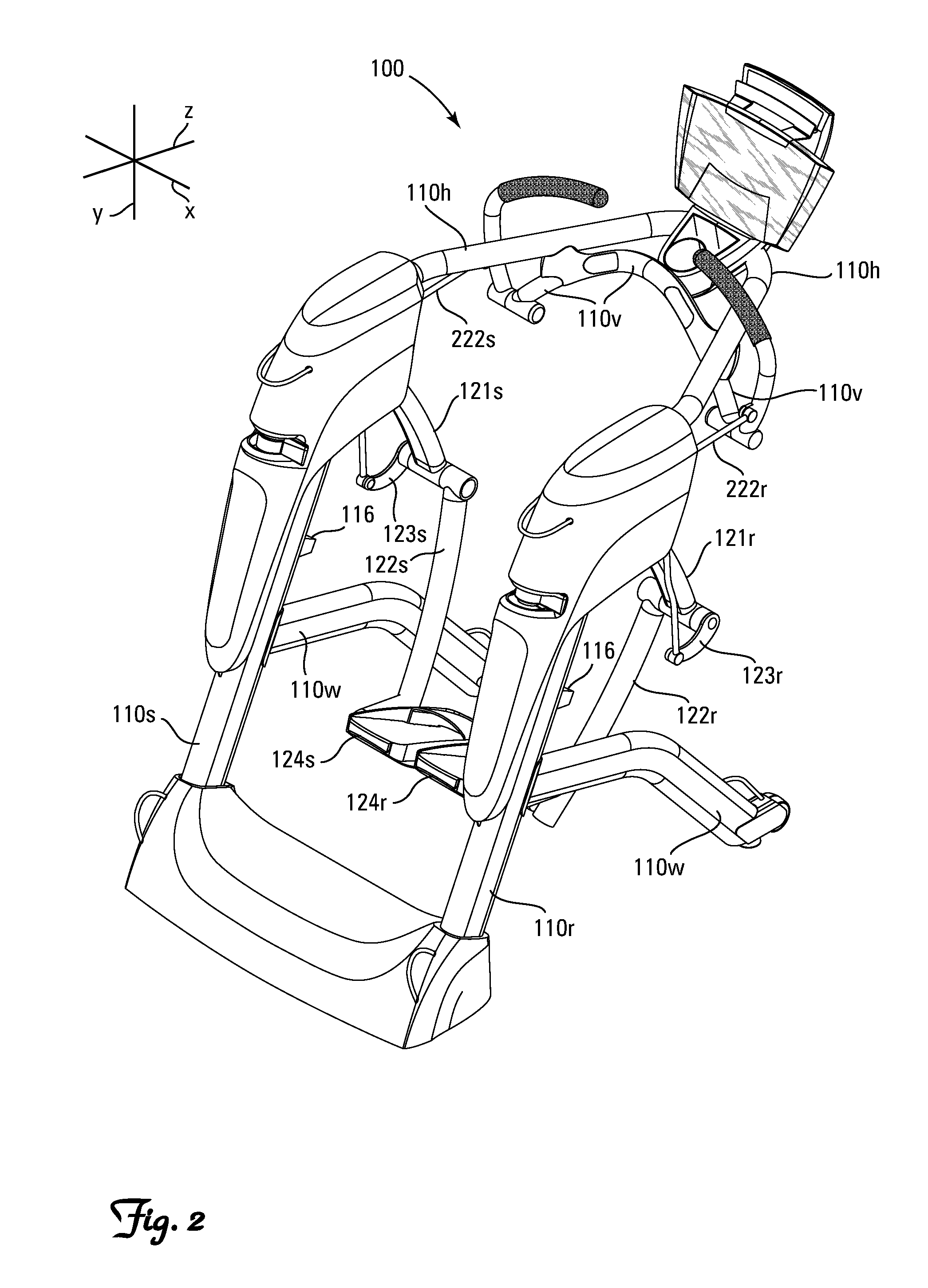
FIG. 2 is a rear isometric view of the invention depicted in FIG. 1.
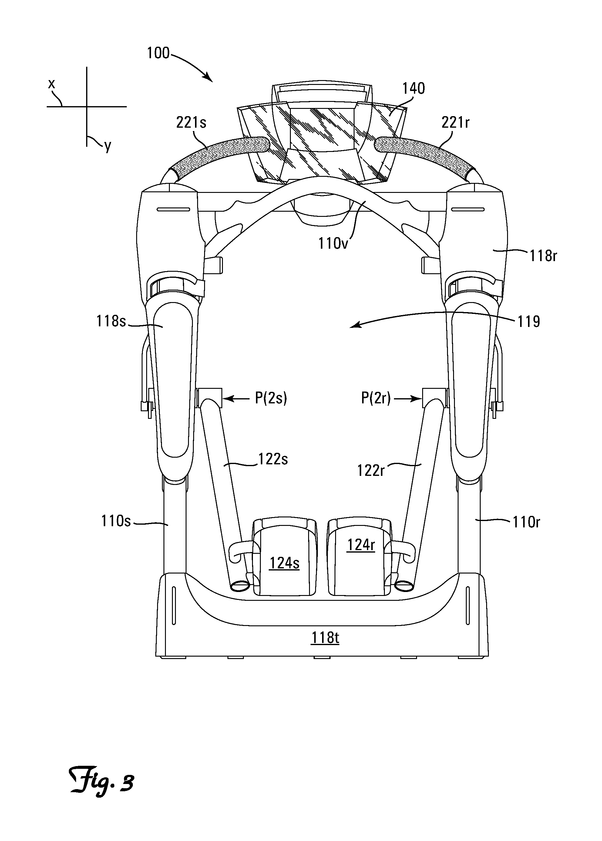
FIG. 3 is a rear view of the invention depicted in FIG. 1.
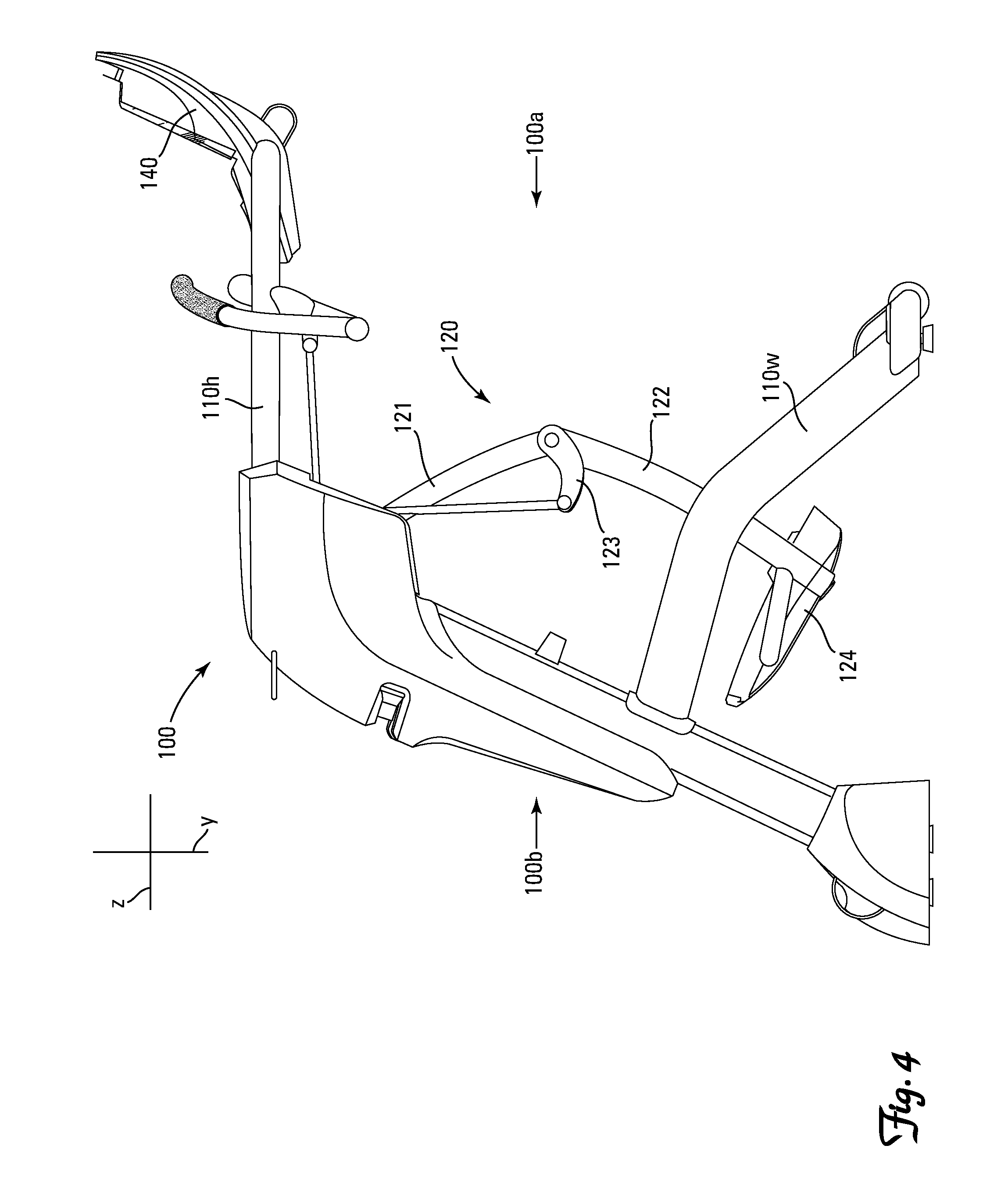
FIG. 4 is a right-side view of the invention depicted in FIG. 1.
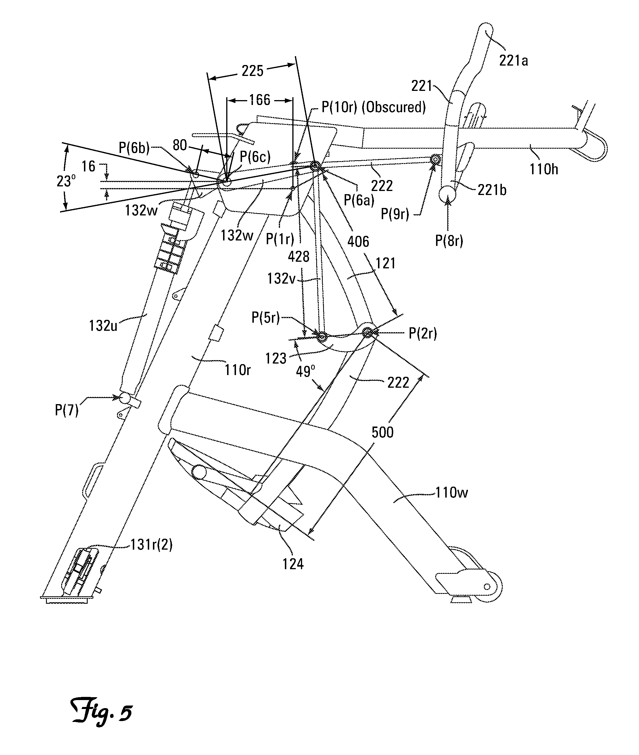
FIG. 5 is a right-side view of the invention depicted in FIG. 1 with exemplary dimensions wherein distance is in millimeters and angles are in degrees.
FIG. 6 is a right-side view of the invention depicted in FIG. 1 with portions of the frame removed to facilitate viewing of internal components.
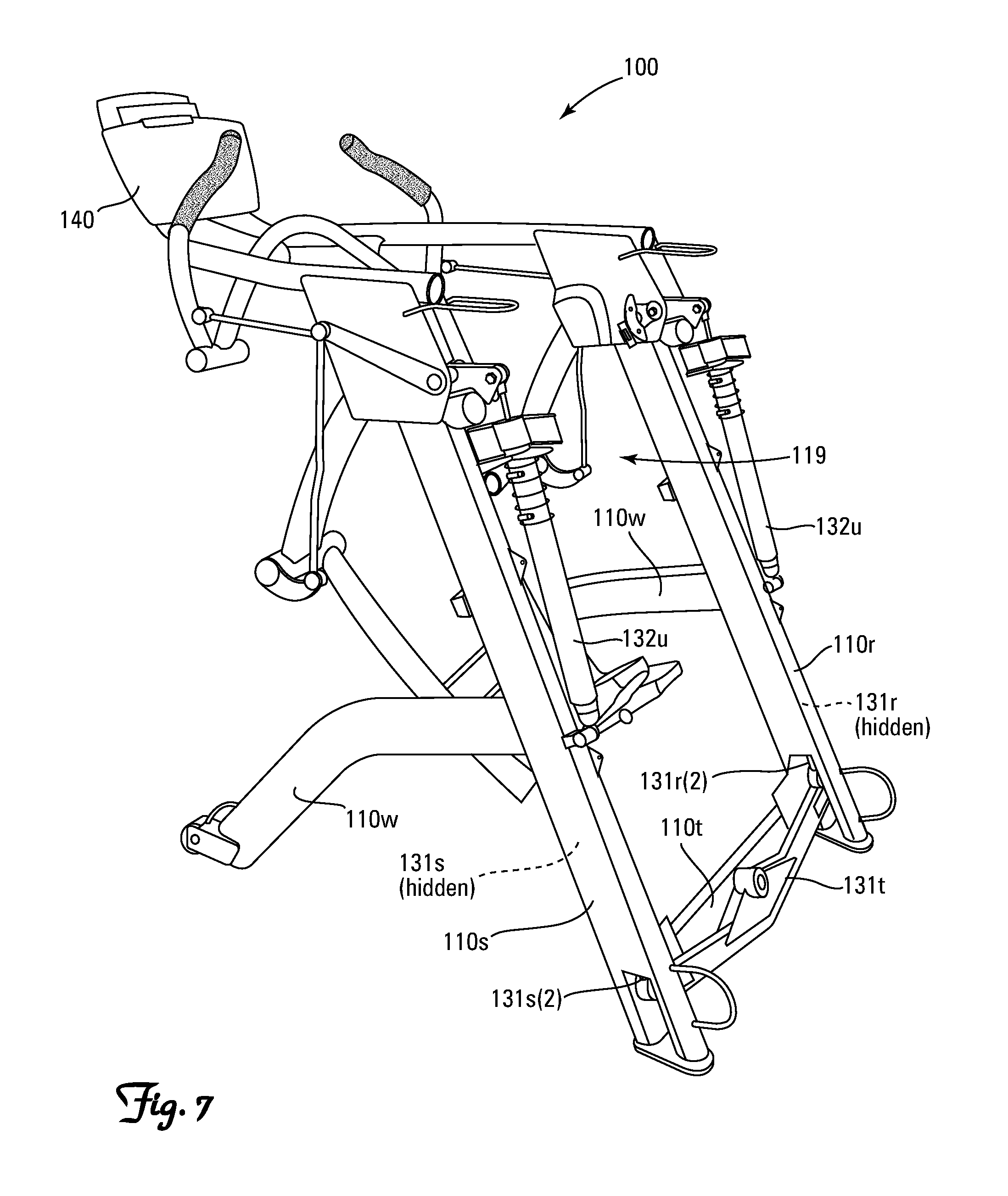
FIG. 7 is a rear isometric view of the invention depicted in FIG. 1 with protective shrouding removed to facilitate viewing of internal components.
FIG. 8 is a left-side view of the invention depicted in FIG. 7.
FIG. 9 is a close-up rear isometric view of the forward portion of the invention depicted in FIG. 7, including the control console, arm linkages and handrail.
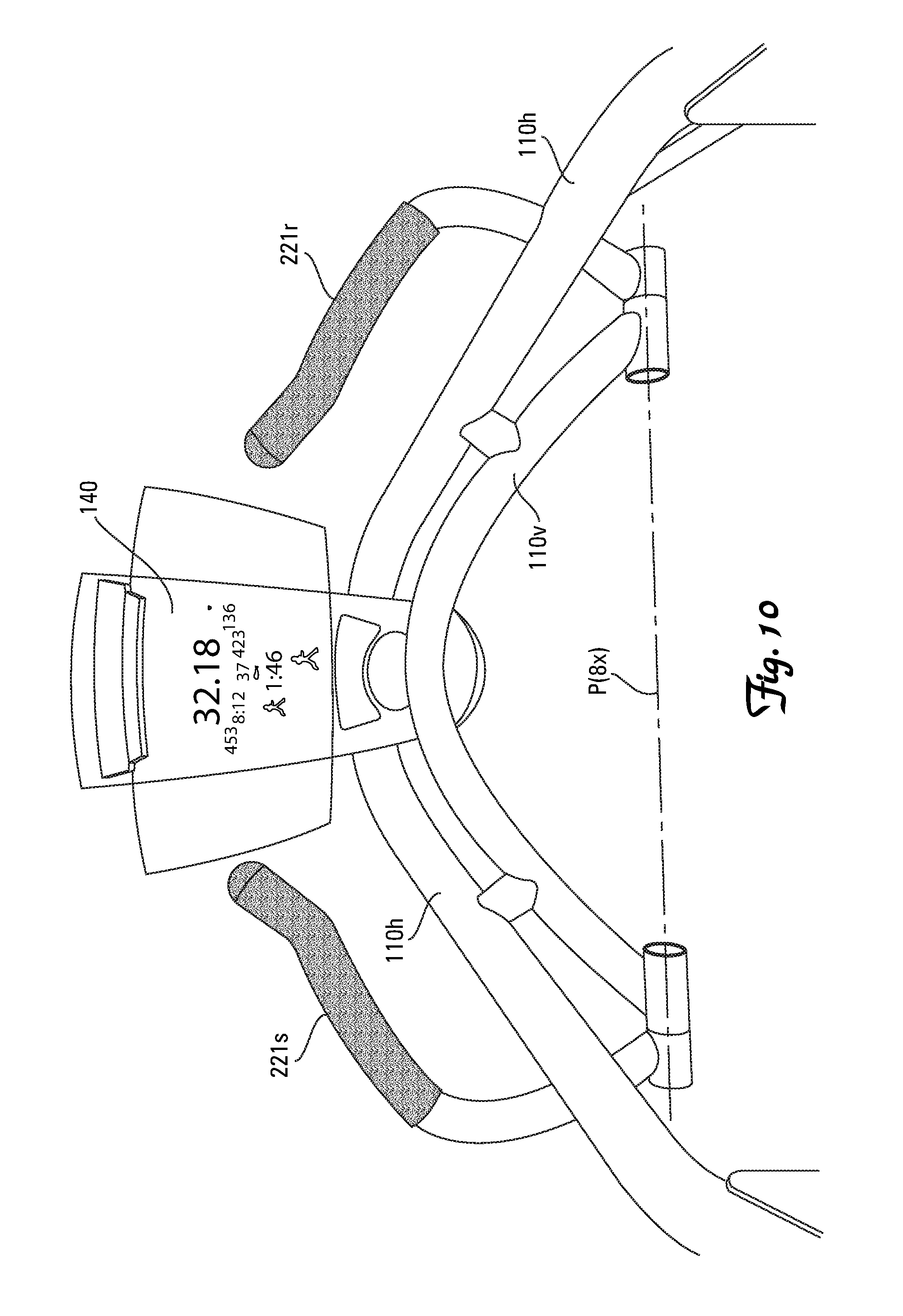
FIG. 10 is the forward portion of the invention depicted in FIG. 9 as viewed by a person using the exercise machine.
FIG. 11 is a close-up, internal front isometric view of the right-side, pivot-manifold area of the invention depicted in FIG. 7.
FIG. 12 is a close-up, front isometric view of the left-side, pivot-manifold area of the invention depicted in FIG. 7.
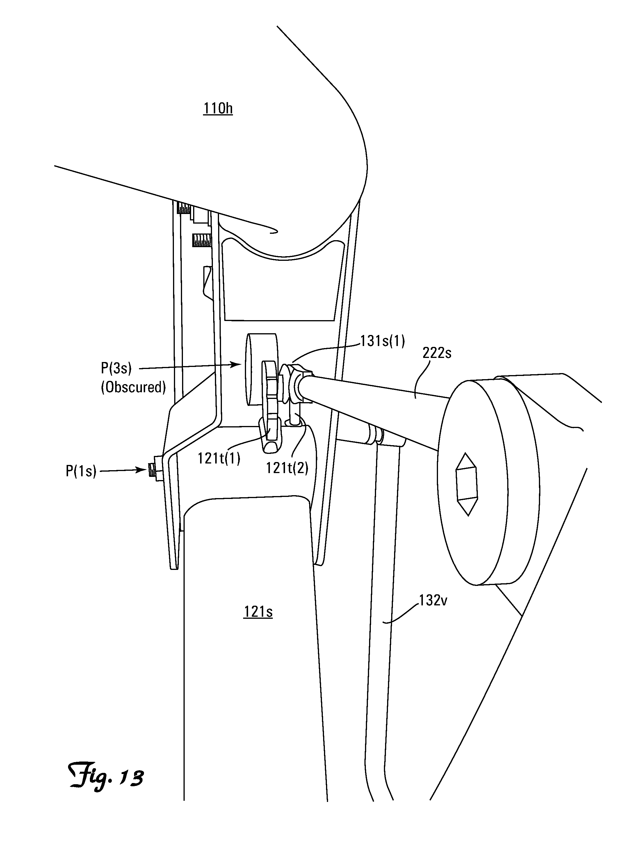
FIG. 13 is a still further enlarged, front view of the left-side pivot-manifold area of the invention depicted in FIG. 7.
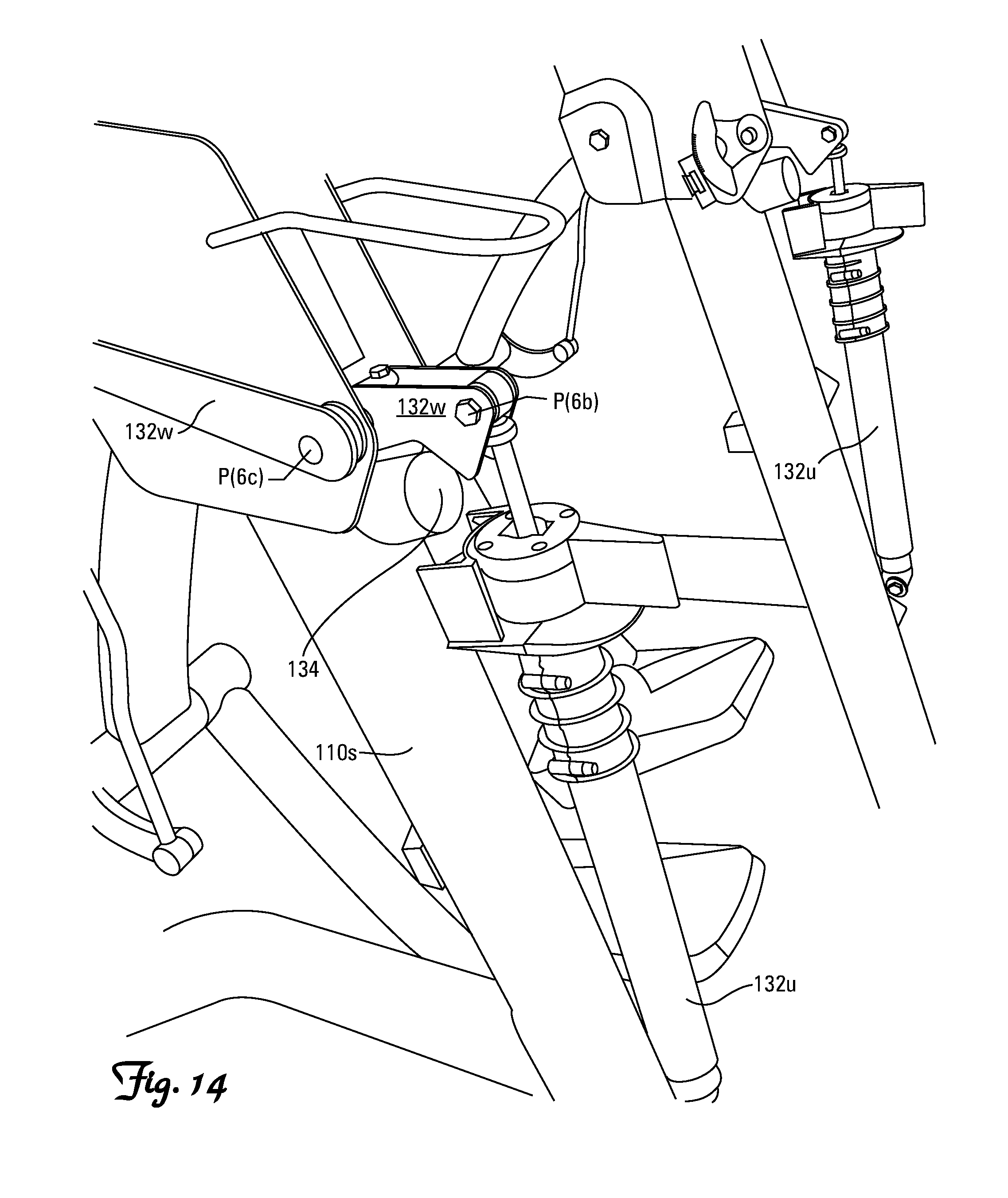
FIG. 14 is a close-up, rear isometric view of the adjustable biased damping components of the invention depicted in FIG. 7.
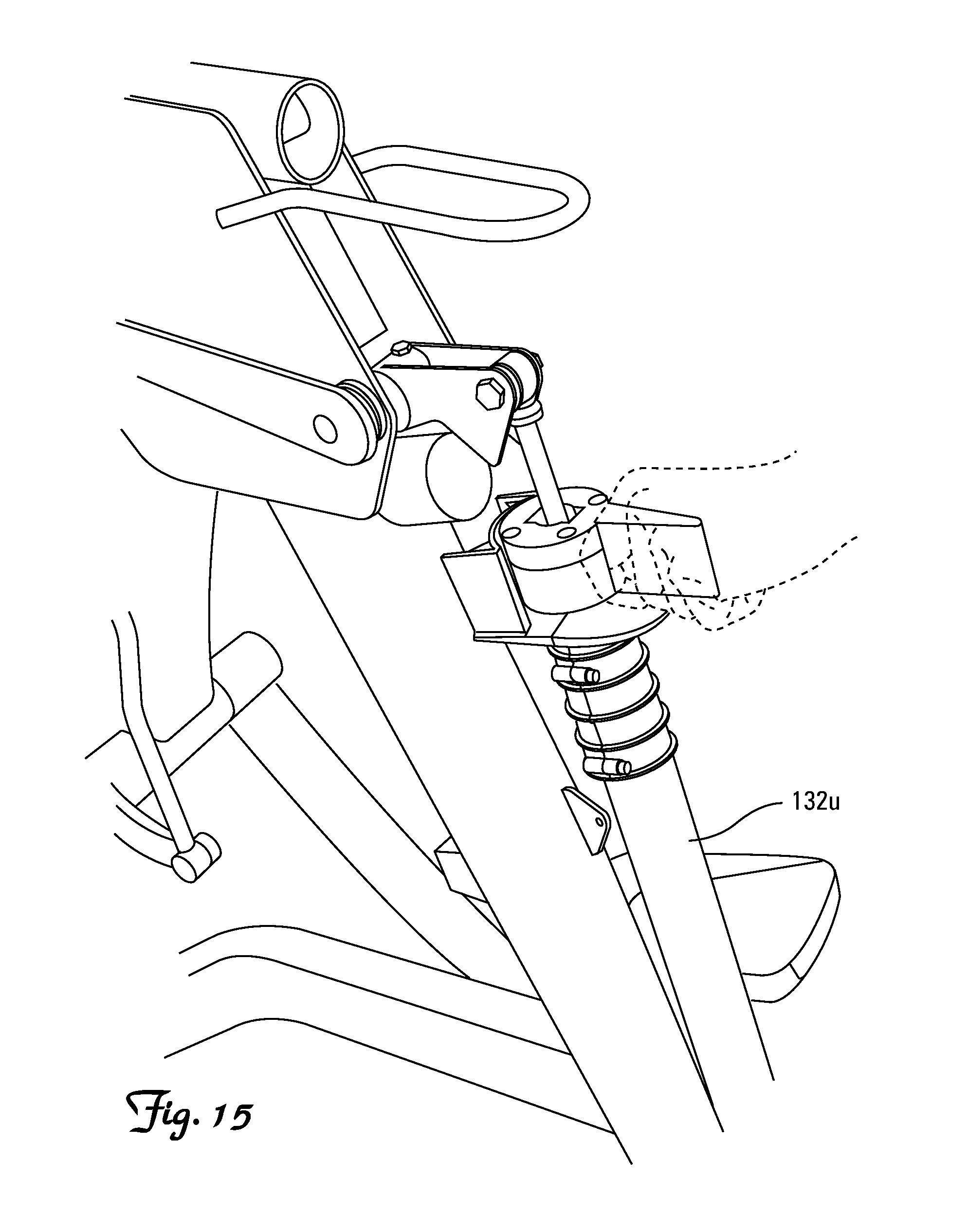
FIG. 15 depicts the adjustable biasing damping components of the invention depicted in FIG. 14 with the left-side biased damping component undergoing manual adjustment.
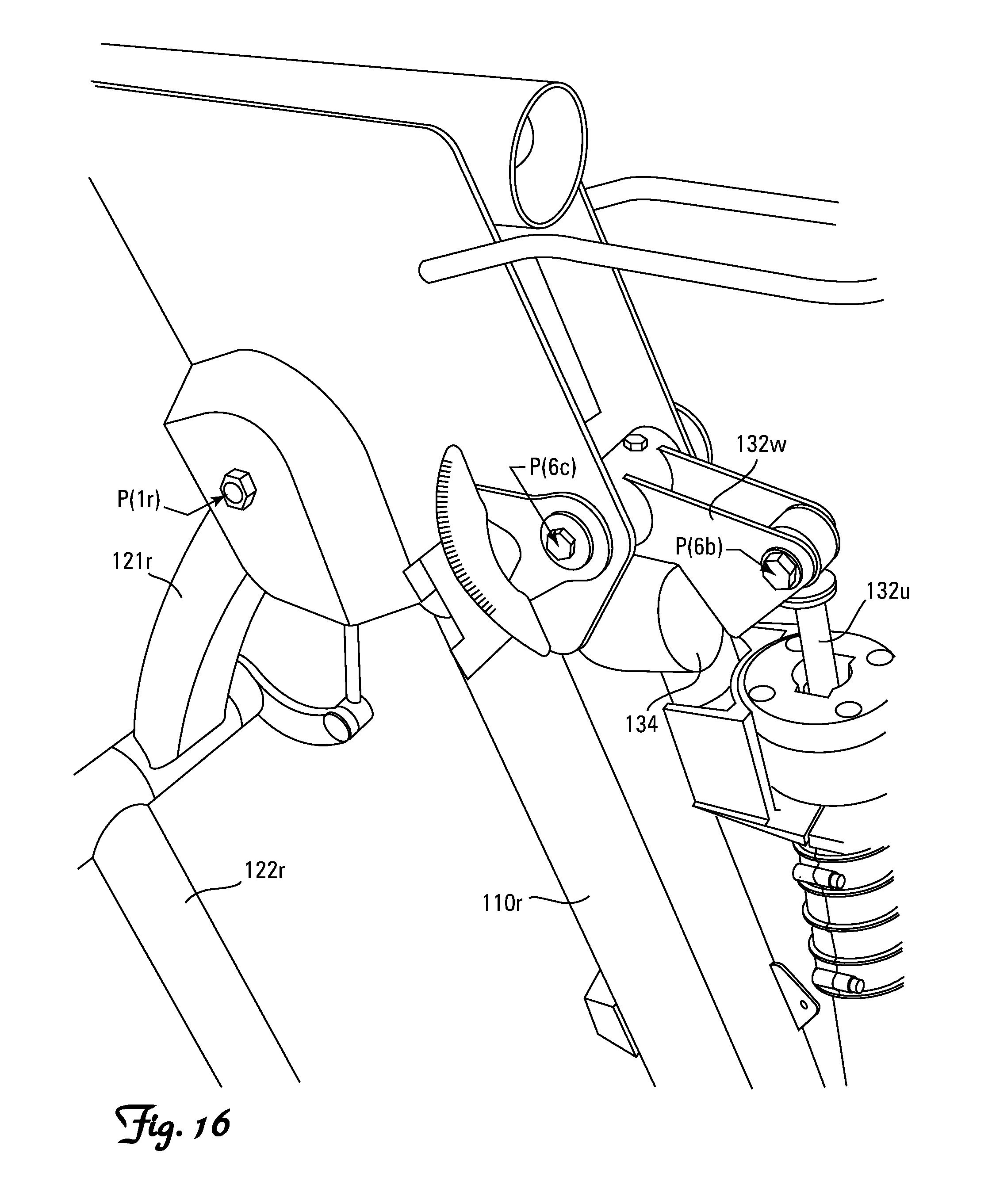
FIG. 16 is a still further enlarged internal rear isometric view of the interface between the right-side pivot-manifold area and the adjustable biased damping component of the invention depicted in FIG. 14.
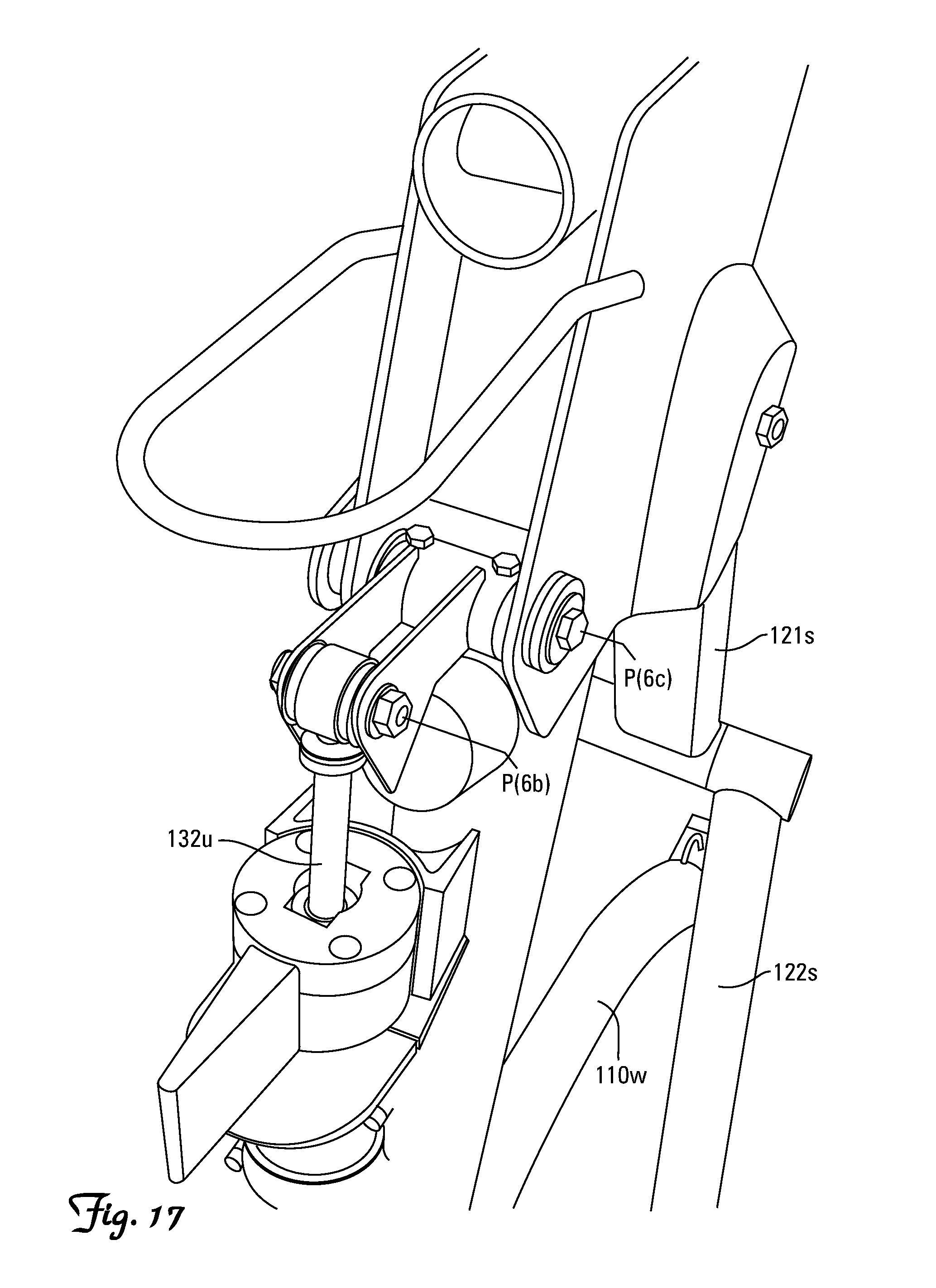
FIG. 17 is a still further enlarged internal rear isometric view of the interface between the left-side pivot-manifold area and the adjustable biased damping component of the invention depicted in FIG. 14.
FIG. 18 is a close-up rear isometric view of the transfer bar component of the invention depicted in FIG. 7.
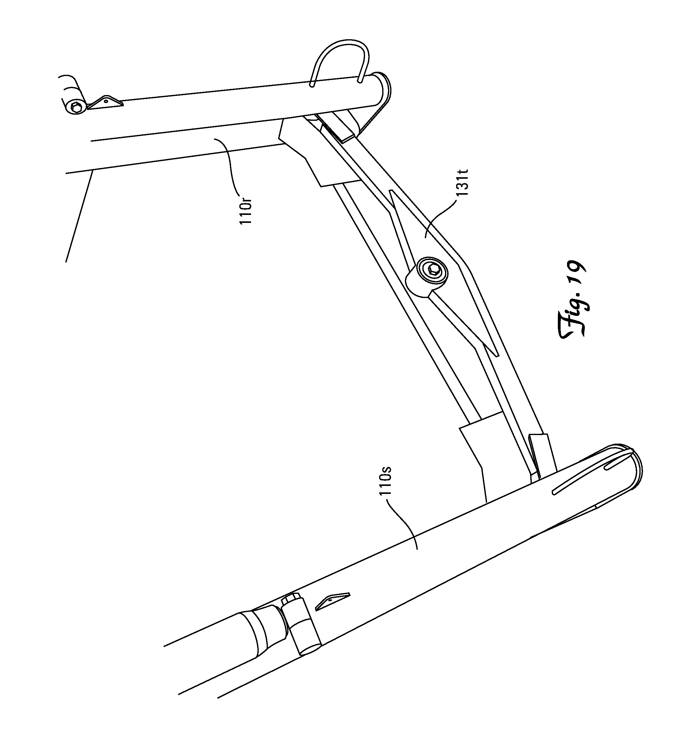
FIG. 19 is another enlarged rear isometric view of the transfer bar component of the invention depicted in FIG. 7.
FIG. 20 is yet another enlarged rear isometric view of the transfer bar component of the invention depicted in FIG. 7.
FIG. 21 is a close-up, internal rear isometric view of the right calf member of the invention depicted in FIG. 7 including the right foot support.
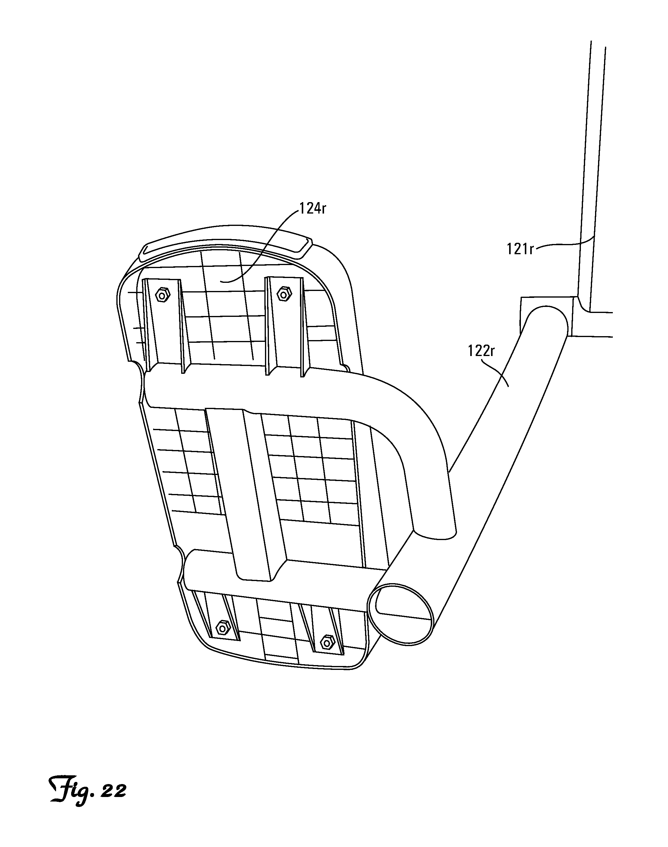
FIG. 22 is a close-up isometric view of the bottom of the right foot support depicted in FIG. 7.
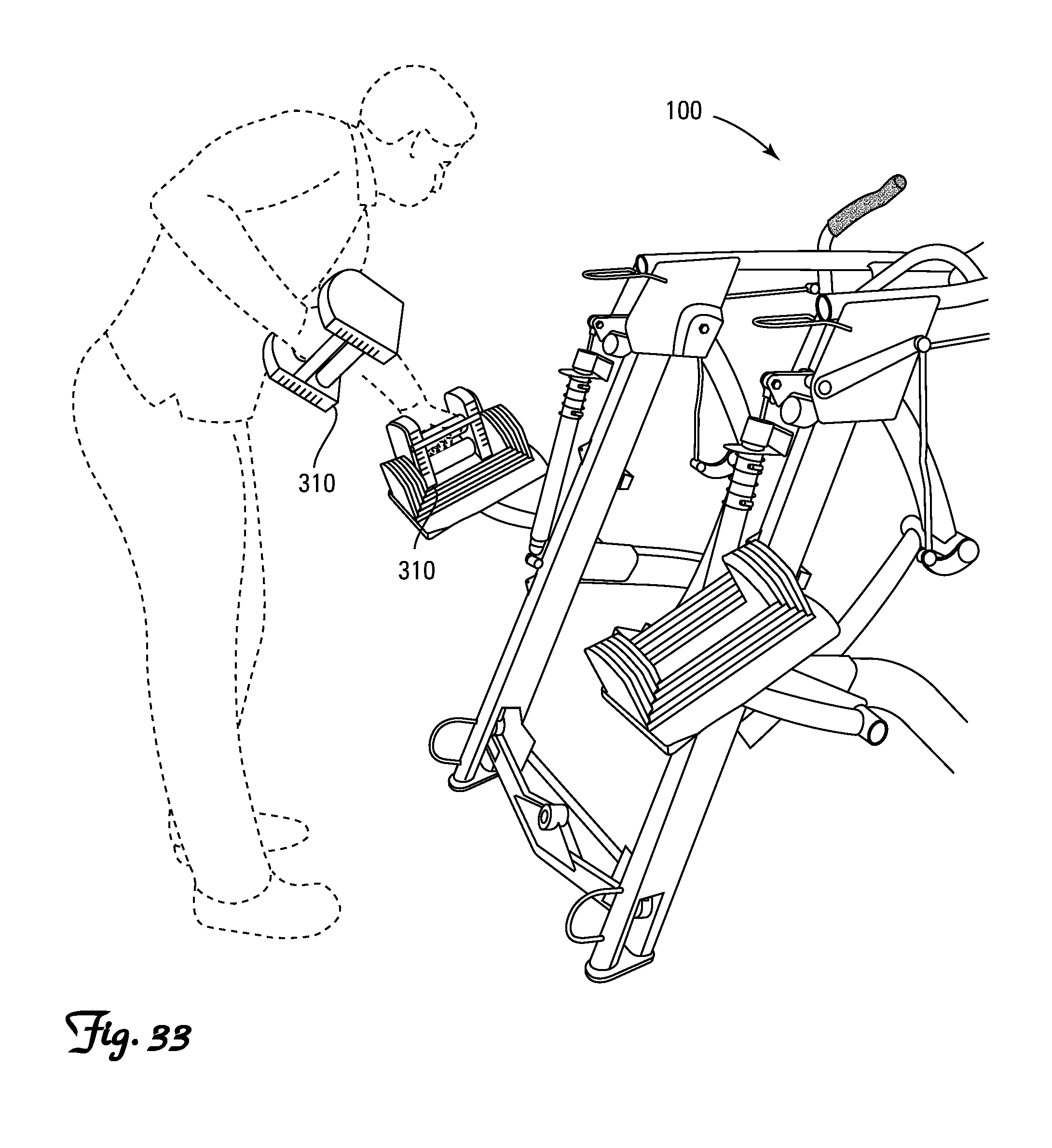
FIG. 23 is a front isometric view of the invention depicted in FIG. 7 equipped with an optional pair of selectorized dumbbells supported on optional shelves attached to the frame of the machine.
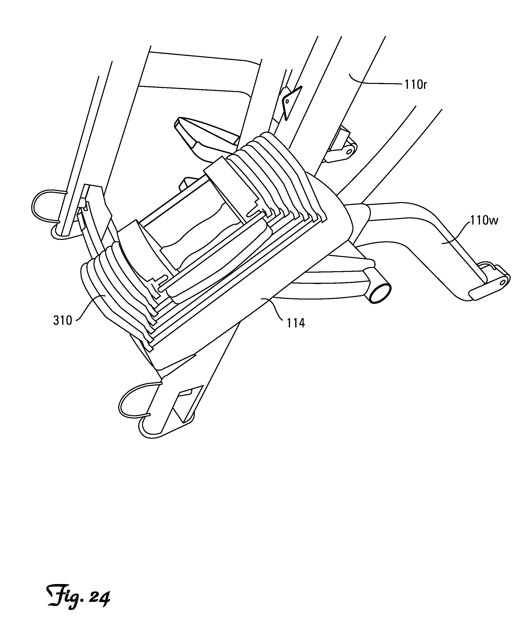
FIG. 24 is a close-up rear isometric view of the right selectorized dumbbell supported on the right shelf depicted in FIG. 23.
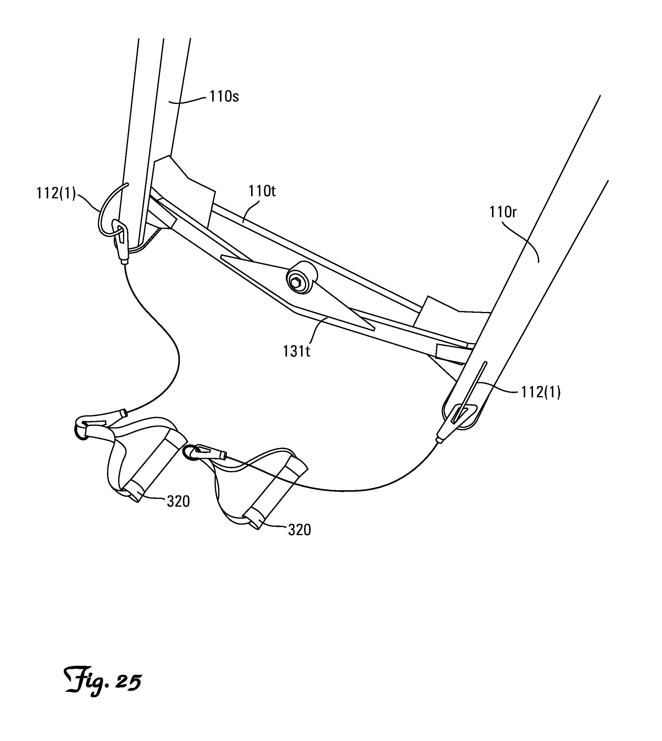
FIG. 25 is a rear isometric view of the base portion of the invention depicted in FIG. 7 equipped with an optional pair of elastic band exercise handles, each attached to a D-ring on the lower end of the right and left stanchions of the frame.
FIG. 26 is a close-up front isometric view of the upper portion of the invention depicted in FIG. 7 equipped with an optional pair of elastic band exercise handles, both attached to a single laterally-centered D-ring on the handrail.
FIG. 27 is a left-side view of the invention depicted in FIG. 7 with an orthostatic forward facing suited user supported upon the foot supports with the foot supports substantially horizontally and almost perfectly vertically aligned.
FIG. 28 is a front isometric view of the invention depicted in FIG. 7 with an orthostatic forward facing suited user supported upon the foot supports with the foot supports horizontally and vertically aligned.
FIG. 29 is a rear isometric view of the invention depicted in FIG. 7 with a forward facing suited user walking on the exercise machine.
FIG. 30 is a rear isometric view of the invention depicted in FIG. 7 with a forward facing suited user running on the exercise machine.
FIG. 31 is a left-side view of the invention depicted in FIG. 7 with a forward facing suited user running on the exercise machine.
FIG. 32 is another left-side view of the invention depicted in FIG. 7 with a forward facing suited user running on the exercise machine.
FIG. 33 is a rear view of the invention depicted in FIG. 23 with a suited user preparing to perform a strength training exercise using the selectorized dumbells.
FIG. 34 is a rear view of the invention depicted in FIG. 23 with a suited user performing a strength training exercise using the selectorized dumbells.
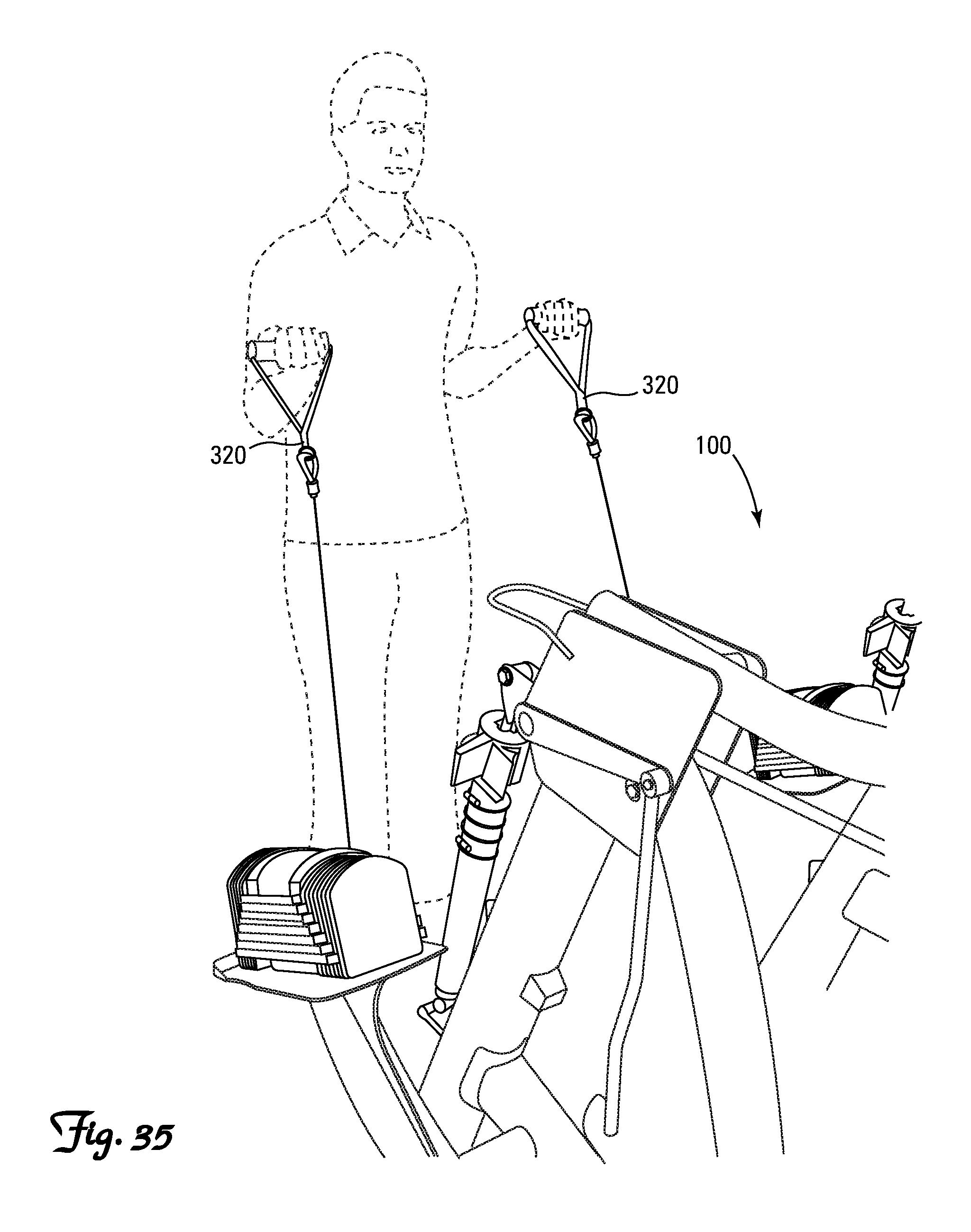
FIG. 35 is a front view of the invention depicted in FIG. 25 with a suited user performing a strength training exercise using the pair of elastic band exercise handles attached to the D-rings on the lower end of the right and left stanchions of the frame.
FIG. 36 is a rear view of the invention depicted in FIG. 25 with a suited user performing a strength training exercise using the pair of elastic band exercise handles attached to the D-rings on the lower end of the right and left stanchions of the frame.
FIG. 37 is a front view of the invention depicted in FIG. 25 with a suited user performing a strength training exercise using the pair of elastic band exercise handles attached to the D-rings on the upper end of the right and left stanchions of the frame.
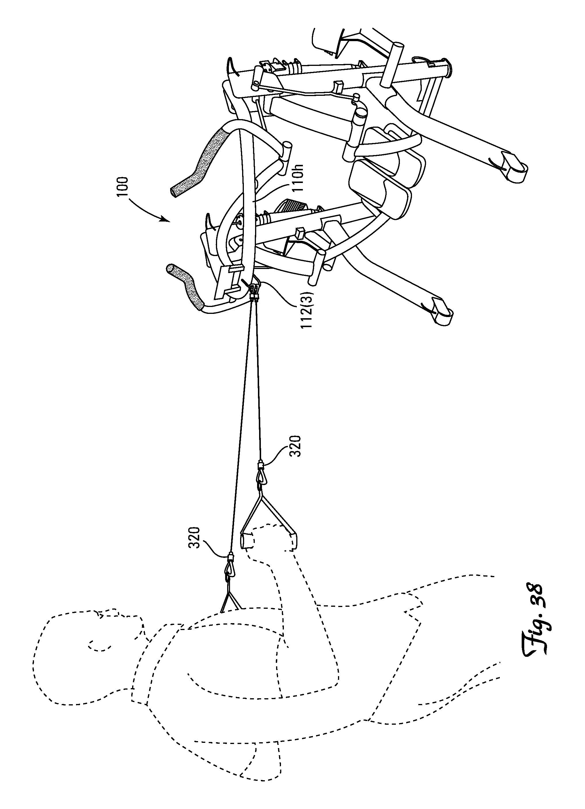
FIG. 38 is a front view of the invention depicted in FIG. 26 with a suited user performing a strength training exercise using the pair of elastic band exercise handles attached to the D-ring on the handrail.
DETAILED DESCRIPTION OF A PREFERRED EMBODIMENT
Definitions
As utilized herein, including the claims, the term "rest position" means the position of the leg links when an orthostatic forward facing user is supported solely by and upon the foot supports with the foot supports horizontally and vertically aligned.
As utilized herein, including the claims, the term "suited user" means a user whose physique is suited for ergonomic exercising on a defined exercise machine.
As utilized herein, including the claims, the phrase "positioned proximate a knee" means within a four inch parasagittal plane radius from the forwardmost surface of the patella, without regard to left-right lateral distance.
As utilized herein, including the claims, a "stationary lower body mimetic exercise machine" refers to an exercise machine having a stationary frame supporting a pair of leg linkages (i.e., left and right leg linkages), with each leg linkage having (i) an upper or thigh link pivotally coupled proximate its upper end to the frame at an upper or hip pivot point, (ii) a lower or calf link pivotally coupled proximate its upper end to the lower end of the thigh link at a lower or knee pivot point, and (iii) a foot support on the lower end of each calf link configured for supporting a user in a standing position during exercise.
NOMENCLATURE
100 Exercise Machine 100a Forward End of Exercise Machine 100b Rearward End of Exercise Machine 110 Frame 110r Right-Side Stanchion 110s Left-Side Stanchion 110t Step-Over Support Beam 110h Horizontal Looped Handrail 110v Vertical Looped Cross Beam Handrail 110w Support Legs 112 D-Rings 112.sub.1 D-Ring Proximate Lower End of Each Stanchion 112.sub.2 D-Ring Proximate Upper End of Each Stanchion 112.sub.3 D-Ring Proximate Lateral Center of Handrail 114 Free-Weight Support Shelf 116 Thigh Member Stop 118r Protective Shroud Over Right Leg Linkage Power Transmission Hub 118s Protective Shroud Over Left Leg Linkage Power Transmission Hub 118t Protective Shroud Over Transfer Bar 119 Access Opening in Frame 120 Leg Linkage 120r Right Leg Link 120s Left Leg Link 121 Thigh Member of Leg Links 121a Upper End of Thigh Members 121b Lower End of Thigh Members 121r Right Thigh Member 121s Left Thigh Member 121t.sub.1 First Tab Extending from Upper End of Thigh Members 121t.sub.2 Second Tab Extending from Upper End of Thigh Members 122 Calf Member of Leg Links 122a Upper End of Calf Members 122b Lower End of Calf Members 122r Right Calf Member 122s Left Calf Member 123 Calf Member Extension Arm 123r Right Calf Member Extension Arm 123s Left Calf Member Extension Arm 124 Foot Supports 124r Right Foot Support 124s Left Foot Support 130 Power Transmission Systems 131 Thigh Articulator Members 131r Right Thigh Articulator Member 131r.sub.1 First End of Right Thigh Articulator Member 131r.sub.2 Second End of Right Thigh Articulator Member 131s Left Thigh Articulator Member 131s.sub.1 First End of Left Thigh Articulator Member 131s.sub.2 Second End of Left Thigh Articulator Member 131t Center Pivot Thigh Motion Transfer Bar 131t.sub.1 First End of Thigh Motion Transfer Bar 131t.sub.2 Second End of Thigh Motion Transfer Bar 132 Calf Motion Biased Damping System 132u Calf Biased Damping Means (e.g., Hydraulic Extension Damped Spring Contraction Biased Piston and Cylinder) 132v Interconnect Member 132w Bell Crank 134 Bell Crank Stop 140 Control Console 220 Arm Linkages 221 Articulating Arm Member 221a Upper End of Articulating Arm Members 221b Lower End of Articulating Arm Members 221r Right Articulating Arm Member 221s Left Articulating Arm Member 222 Arm Articulation Members 222r Right Arm Articulation Member 222s Left Arm Articulation Member 310 Selectorized Dumbells 320 Elastic Band Exercise Handles P.sub.1 Hip Pivot Points P.sub.1r Right Hip Pivot Point P.sub.1s Left Hip Pivot Point P.sub.1x Lateral Axis Through Hip Pivot Points P.sub.2 Knee Pivot Points P.sub.2r Right Knee Pivot Point P.sub.2s Left Knee Pivot Point P.sub.3r Right Thigh Member--Thigh Articulator Member Pivot Point P.sub.3s Left Thigh Member--Thigh Articulator Member Pivot Point P.sub.4c Center Pivot on Transfer Bar P.sub.4r Right Pivot on Transfer Bar P.sub.4s Left Pivot on Transfer Bar P.sub.5r Right Calf Member Extension Arm--Interconnect Member Pivot Point P.sub.5s Left Calf Member Extension Arm--Interconnect Member Pivot Point P.sub.6a First End Pivot on Bell Crank P.sub.6b Second End Pivot on Bell Crank P.sub.6c Center Pivot on Bell Crank P.sub.7 Calf Biased Damper--Frame Pivot Point P.sub.8r Right Articulating Arm Member Pivot Point P.sub.8s Left Articulating Arm Member Pivot Point P.sub.8x Lateral Axis Through Articulating Arm Member Pivot Points P.sub.9r Right Articulating Arm Member--Arm Articulation Member Pivot Point P.sub.9s Left Articulating Arm Member--Arm Articulation Member Pivot Point P.sub.10r Right Arm Articulation Member--Thigh Member Pivot Point P.sub.10s Left Arm Articulation Member--Thigh Member Pivot Point x Lateral Direction y Longitudinal Direction z Transverse Direction H Human or User Construction
With reference to the illustrative drawings, and particularly to FIGS. 1-38, the invention is directed to a lower body mimetic stationary exercise machine 100 with fully or partially autonomous right and left leg linkages 120 and ergonomically positioned hip P.sub.1 and/or knee P.sub.2 pivot points. The autonomous links on the leg linkages 120 preferably communicate with a biased damping system 132 configured and arranged for damping or resisting movement of the autonomous link when a user H applies motive, typically downward, force to the corresponding foot support 124, and biasing the autonomous link to follow movement of the user H when the user H is moving away, typically lifting, from the corresponding foot support 124.
Referring generally to FIGS. 1-8, the lower body mimetic stationary exercise machine 100 is symmetrical about the midsagittal plane of the machine 100 so as to provide mirror image right (r) and left (s) sides. For simplicity the detailed discussion will generally collectively reference the right (r) and left (s) components, while the drawings will generally call-out the corresponding right (r) and left (s) components individually.
The machine 100 a lower body mimetic stationary exercise machine that includes a frame 110, leg linkages 120, power transmission systems 130, and a control console 140. The machine 100 optionally and preferably also includes arm linkages 220 and component for facilitating access and usage of strength training components such as selectorized dumbbells 310 and elastic band exercise handles 320.
The exercise machine 100 includes a frame 110. An exemplary frame 110, depicted generally in FIGS. 1-8, defines a relatively inaccessible forward end 100a of the machine 100 and an accessible rearward end 100b of the machine 100 defining an access opening 119 in the frame 110. The frame 110 includes longitudinally y extending right and left stanchions 110r and 110s proximate the rear 110b of the frame 110, a laterally x extending step-over support beam 110t interconnecting the base of the right and left stanchions 110r and 110s, a horizontal looped handrail 110h interconnecting the top of the right and left stanchions 110r and 110s, a laterally x extending vertical looped cross-beam handrail 110v attached to the forward end of the horizontal looped handrail 110h, and transversely z extending support leg 110w extending forward from each of the right and left stanchions 110r and 110s.
The exercise machine 100 includes right and left leg linkages 120r and 120s. An exemplary pair of leg linkages 120 is depicted generally in FIGS. 1-8. Each leg linkage 120 includes a thigh member 121 pivotally attached proximate the upper end 121a to the frame 110 at a hip pivot point P.sub.1, a calf member 122 pivotally attached proximate the upper end 122a to the lower end 121b of the thigh member 121 at a knee point P.sub.2, and a foot support 124 attached to the lower end 122b of the calf member 122. The right and left hip pivot points P.sub.1r and P.sub.1s define a lateral hip pivot axis P.sub.1x that remains static during use of the machine 100.
Elastic stops 116, preferably of high durometer rubber, may be provided on the forward surface of the right and left stanchions 110r and 110s to prevent the thigh members 121r and 121s from over-rotating and striking the right and left stanchions 110r and 110s.
The thigh member 121, calf member 122, and foot support 124 should be configured and arranged such that (1) the lateral hip pivot axis P.sub.1x will pass through or posterior to the hip region of an orthostatic forward facing suited user H supported upon the foot supports 124 with the foot supports 124 horizontally and vertically aligned, and/or (2) each of the knee pivot points P.sub.2 are positioned proximate the corresponding knee of an orthostatic forward facing suited user H supported upon the foot supports 124 with the foot supports 124 horizontally and vertically aligned.
Each of the right and left thigh members 121r and 121s and right and left calf members 122r and 122s members on the right and left leg linkages 120r and 120s should be connected to a power transmission system selected from a left-right motion transfer system 131 or a biased damping system 132. The exemplary machine 100 depicted in FIGS. 1-38 employs a left-right motion transfer system 131 for the thigh members 121 and a biased damping system 132 for the calf members. Other combinations are possible, such as employing a biased damping system 132 for the thigh members 121 and a left-right motion transfer system 131 for the calf members, employing a left-right motion transfer system 131 for both the thigh members 121 and the calf members 122, and employing a biased damping system 132 for both the thigh members 121 and the calf members 122. Each of these combinations possesses certain unique refinements in interaction between the machine and its human operator.
An exemplary left-right motion transfer system 131 deployed in connection with the thigh members 121 is depicted generally in FIGS. 6, 7 and 18-20. Right and left articulator members 131r and 131s are pivotally attached at a first end 131r.sub.1 and 131s.sub.1 to a second tab 121t.sub.2 projecting from the upper end 121a of the respective right and left thigh members 121r and 121s, at right and left pivot points P.sub.3r and P.sub.3s. The articulator members 131r and 131s can be conveniently and protectively housed within the corresponding stanchion 110r and 110s for extension down to the bottom of each stanchion 110r and 110s proximate the step-over support beam 110t.
The right and left articulator members 131r and 131s are each pivotally attached at the other end 131r.sub.2 and 131s.sub.2 to opposite ends 131t.sub.1 and 131t.sub.2 of a laterally x extending center pivot motion transfer bar 131t for pivoting about pivot points P.sub.4r and P.sub.4s respectively. The center pivot motion transfer bar 131t is centrally pivotally attached to the step-over support beam 110t at pivot point P.sub.4c, whereby longitudinal y reciprocation of one articulator members 131, effected by user H induced movement of one of the thigh members 121, effects pivoting of the center pivot motion transfer bar 131t about pivot point P.sub.4c, thereby producing an equal and opposite longitudinal y reciprocation of the other articulator member 131 and hence a corresponding pivoting of the other thigh member 121 about the corresponding hip pivot point P.sub.1.
An exemplary biased damping system 132 deployed in connection with the calf members 122 is depicted generally in FIGS. 5-8 and 14-17. Pivotal movement of each calf member 122r and 122s is independently communicated to and controlled by a biased damping means 132u, such as a hydraulic extension damped spring contraction biased piston and cylinder depicted in the figures, through a calf member extension arm 123, an interconnect member 132v and a bell crank 134 pivotally attached at a center pivot point P.sub.6c to the frame 110 proximate the top of the corresponding stanchion 110r and 110s.
The calf member extension arm 123 is rigidly affixed to the calf member 122 for pivoting with the calf member 122 about the knee pivot point P.sub.2. The distal end of the extension arm 123 is pivotally attached to one end of the interconnect member 132v for pivoting about a pivot point P.sub.5. The other end of the interconnect member 132v is pivotally attached to one end of the bell crank 134 for pivoting about a first pivot point P.sub.6a on the bell crank 134. The other end of the bell crank 134 is pivotally attached to the biased damping means 132u for pivoting about a second pivot point P.sub.6b, which for the embodiment illustrated in the Figures is the piston rod component of a hydraulic extension damped spring contraction biased piston and cylinder. The opposite end of the damping means 132u is pivotally attached to the frame for pivoting about pivot point P.sub.7 to accommodate the modest transverse x movement imposed upon the damping means 132u by pivoting of the bell crank 134.
A variety of suitable biased damping devices, either integrated into a single device or employed as separate biasing and damping devices, are readily commercially available from a number of sources. Selection of biasing and damping forces exerted by the biased damping means 132u to attain the desired level of interaction between user H and machine 100 depends in large measure upon the size of the intended user H and the configuration of the machine 100, particularly those aspects of machine 100 design that impact the size of the various lever arms on the machine 100 that communicate with the biased damping means 132u. By way of example, a hydraulic damped spring biased piston and cylinder having the following performance specifications has been found to be suitable for use with an exercise machine 100 having the dimensions set forth in FIG. 5. A force adjustable biased damping means 132u is preferred as it permits user H customization of this feature based upon user H height, weight, age, fitness level, etc. as well as personal preferences.
Damper Force: At Minimum Selling: 55.+-.5 Kgf At Maximum Setting: 145.+-.10 Kgf With The Following Test Parameters: at a Temperature of 25-30.degree. C. with Spring Installed Initial Length: 540 mm Eyelet Center To Eyelet Center Final Length: 640 mm Eyelet Center To Eyelet Center Crank Speed of Crank Slider Test Set-Up: 29.4 rpm Equivalent Peak Velocity: 155 mm/sec
Spring Force: Spring Rate: 7 lbs/in initial SPRING FORCE: 35 lbs force
In operation, pivoting of the calf member 122 about the knee pivot point P.sub.2, and to a lesser extent movement of the knee pivot point P.sub.2 relative to the frame 110 as a result of pivoting of the corresponding thigh member 121 about the hip pivot point P.sub.1, produces a relatively linear longitudinal y translation of the interconnect member 132v. Such linear movement of the interconnect member 132v causes the bell crank 134 to pivot about the center pivot point P.sub.6c and thereby effect relatively linear longitudinal y translation of the piston within the cylinder in the opposite direction.
Elastic stops 134, preferably of high durometer rubber, may be provided on the rearward surface of the right and left stanchions 110r and 110s to prevent the bell crank 132w from over-rotating and striking the right and left stanchions 110r and 110s.
The exercise machine 100 is equipped with a control console 140 equipped with a display and a user input device in accordance with standard industry practice. The console 140 may conveniently be mounted onto the forward end of the horizontal looped handrail 110h facing the access opening 119 in the rear of the machine 100.
The machine 100 is optionally but preferably equipped with articulating arm linkages 220 for permitting upper body exercise. Articulation of the articulating arm linkages 220 is preferably linked to movement of the leg linkages 120. An exemplary articulating arm linkage is depicted generally in FIGS. 1-10, 12 and 13. Right and left articulating arm members 221r and 221s are pivotally attached at a lower end 221b proximate the right and left ends of the vertical looped cross beam handrail 110v for pivoting about right and left pivot points P.sub.8r and P.sub.8s respectively. Right and left arm articulation members 222r and 222s are pivotally attached at one end to the corresponding articulating arm member 221r and 221s for pivoting about pivot point P.sub.9r and P.sub.9s respectively. The other end of the articulation members 222r and 222s are pivotally attached to a first tab 121t.sub.1 projecting from the upper end 121a of the respective right and left thigh members 121r and 121s for pivoting about pivot point P.sub.10r and P.sub.10s respectively.
In operation, pivoting of a thigh member 121 about the hip pivot point P.sub.1, produces a relatively linear transverse z translation of the connected articulation member 222. Such linear movement of the articulation member 222 causes the attached articulating arm member 221 to pivot about pivot point P.sub.8, thereby producing forward and back reciprocation of the articulation member 222 in a transverse z direction that is opposite that of the interconnected thigh member 121.
Referring to FIGS. 1-4, protective shrouding 118r and 118s should be provided over the leg linkage power transmission hubs located proximate the upper end of the right and left stanchions 110r and 110s respectively. Protective shrouding 118t should also be provided over the transfer bar 131t on the step-over support beam 110t.
D-rings 112 or similar connective devices can be provided on the frame 110 for connecting elastic band exercise handles 320 or other similar strength training devices to the frame 110. FIGS. 1-8, 24-26 and 35-38 illustrate exemplary placement of D-rings 112 on the frame 110 with a first pair 112.sub.1 at the lower ends of the right and left stanchions 110r and 110s, a second pair 112.sub.2 at the upper ends of the right and left stanchions 110r and 110s, and a lone ring 112.sub.3 at the lateral x center of the horizontal looped handrail 110h.
As illustrated in FIGS. 23, 24 and 33-38, shelves 114 can be provided on each side of the frame 110 for supporting free weights such as selectorized dumbbells 310 at a readily accessible and convenient location.
* * * * *
D00000
D00001
D00002
D00003
D00004
D00005
D00006
D00007
D00008
D00009
D00010
D00011
D00012

D00013
D00014
D00015
D00016
D00017
D00018

D00019
D00020

D00021

D00022
D00023

D00024
D00025
D00026

D00027

D00028

D00029

D00030

D00031

D00032

D00033
D00034

D00035
D00036

D00037

D00038
XML
uspto.report is an independent third-party trademark research tool that is not affiliated, endorsed, or sponsored by the United States Patent and Trademark Office (USPTO) or any other governmental organization. The information provided by uspto.report is based on publicly available data at the time of writing and is intended for informational purposes only.
While we strive to provide accurate and up-to-date information, we do not guarantee the accuracy, completeness, reliability, or suitability of the information displayed on this site. The use of this site is at your own risk. Any reliance you place on such information is therefore strictly at your own risk.
All official trademark data, including owner information, should be verified by visiting the official USPTO website at www.uspto.gov. This site is not intended to replace professional legal advice and should not be used as a substitute for consulting with a legal professional who is knowledgeable about trademark law.