Prosthetic heart valve having tubular seal
Lin , et al. Feb
U.S. patent number 10,201,417 [Application Number 15/008,790] was granted by the patent office on 2019-02-12 for prosthetic heart valve having tubular seal. This patent grant is currently assigned to BOSTON SCIENTIFIC SCIMED INC.. The grantee listed for this patent is BOSTON SCIENTIFIC SCIMED, INC.. Invention is credited to Patricia Byrne, Cornelius M. Crowley, Christopher B. Finnegan, Nadina Hammer, Dominika Jerczynska, Johnhan Lin, Laura Luong, Christopher M. Miracle, Marissa Pumares.


View All Diagrams
| United States Patent | 10,201,417 |
| Lin , et al. | February 12, 2019 |
Prosthetic heart valve having tubular seal
Abstract
A tubular seal for a prosthetic heart valve includes an elastomeric polymer matrix and a plurality of non-elastic fibers retained within the matrix. The non-elastic fibers can be arranged in the elastomeric polymer matrix to allow the tubular seal to stretch in axial and radial directions.
| Inventors: | Lin; Johnhan (San Jose, CA), Miracle; Christopher M. (Walnut Creek, CA), Finnegan; Christopher B. (Los Gatos, CA), Crowley; Cornelius M. (San Francisco, CA), Hammer; Nadina (San Jose, CA), Pumares; Marissa (San Jose, CA), Jerczynska; Dominika (Castlegar, IE), Byrne; Patricia (County Galway, IE), Luong; Laura (West Sacramento, CA) | ||||||||||
|---|---|---|---|---|---|---|---|---|---|---|---|
| Applicant: |
|
||||||||||
| Assignee: | BOSTON SCIENTIFIC SCIMED INC.
(Maple Grove, MN) |
||||||||||
| Family ID: | 56553628 | ||||||||||
| Appl. No.: | 15/008,790 | ||||||||||
| Filed: | January 28, 2016 |
Prior Publication Data
| Document Identifier | Publication Date | |
|---|---|---|
| US 20160220360 A1 | Aug 4, 2016 | |
Related U.S. Patent Documents
| Application Number | Filing Date | Patent Number | Issue Date | ||
|---|---|---|---|---|---|
| 62111449 | Feb 3, 2015 | ||||
| Current U.S. Class: | 1/1 |
| Current CPC Class: | A61F 2/2409 (20130101); A61F 2/2412 (20130101); A61F 2/2418 (20130101); A61F 2250/0069 (20130101); A61F 2220/0075 (20130101) |
| Current International Class: | A61F 2/24 (20060101) |
| Field of Search: | ;623/2.1-2.19,1.15-1.48 |
References Cited [Referenced By]
U.S. Patent Documents
| 15192 | June 1856 | Peale |
| 2682057 | June 1954 | Lord |
| 2701559 | February 1955 | Cooper |
| 2832078 | April 1958 | Williams |
| 3029819 | April 1962 | Starks |
| 3099016 | July 1963 | Edwards |
| 3113586 | December 1963 | Edmark, Jr. |
| 3130418 | April 1964 | Head et al. |
| 3143742 | August 1964 | Cromie |
| 3221006 | November 1965 | Moore et al. |
| 3334629 | August 1967 | Cohn |
| 3365728 | January 1968 | Edwards et al. |
| 3367364 | February 1968 | Cruz, Jr. et al. |
| 3409013 | November 1968 | Berry |
| 3445916 | May 1969 | Schulte |
| 3540431 | November 1970 | Mobin-Uddin |
| 3548417 | December 1970 | Kischer et al. |
| 3570014 | March 1971 | Hancock |
| 3587115 | June 1971 | Shiley |
| 3592184 | July 1971 | Watkins et al. |
| 3628535 | December 1971 | Ostrowsky et al. |
| 3642004 | February 1972 | Osthagen et al. |
| 3657744 | April 1972 | Ersek |
| 3671979 | June 1972 | Moulopoulos |
| 3714671 | February 1973 | Edwards et al. |
| 3725961 | April 1973 | Magovern et al. |
| 3755823 | September 1973 | Hancock |
| 3795246 | March 1974 | Sturgeon |
| 3839741 | October 1974 | Haller |
| 3868956 | March 1975 | Alfidi et al. |
| 3874388 | April 1975 | King et al. |
| 3983581 | October 1976 | Angell et al. |
| 3997923 | December 1976 | Possis |
| 4035849 | July 1977 | Angell et al. |
| 4056854 | November 1977 | Boretos et al. |
| 4084268 | April 1978 | Ionescu et al. |
| 4106129 | August 1978 | Carpentier et al. |
| 4222126 | September 1980 | Boretos et al. |
| 4233690 | November 1980 | Akins |
| 4265694 | May 1981 | Boretos et al. |
| 4291420 | September 1981 | Reul |
| 4297749 | November 1981 | Davis et al. |
| 4323358 | April 1982 | Lentz et al. |
| 4326306 | April 1982 | Poler |
| 4339831 | July 1982 | Johnson |
| 4343048 | August 1982 | Ross et al. |
| 4345340 | August 1982 | Rosen |
| 4373216 | February 1983 | Klawitter |
| 4388735 | June 1983 | Ionescu |
| 4406022 | September 1983 | Roy |
| 4423809 | January 1984 | Mazzocco |
| 4425908 | January 1984 | Simon |
| 4470157 | September 1984 | Love |
| 4484579 | November 1984 | Meno et al. |
| 4501030 | February 1985 | Lane |
| 4531943 | July 1985 | Van Tassel et al. |
| 4535483 | August 1985 | Klawitter et al. |
| 4574803 | March 1986 | Storz |
| 4580568 | April 1986 | Gianturco |
| 4592340 | June 1986 | Boyles |
| 4602911 | July 1986 | Ahmadi et al. |
| 4605407 | August 1986 | Black et al. |
| 4610688 | September 1986 | Silvestrini et al. |
| 4612011 | September 1986 | Kautzky |
| 4617932 | October 1986 | Kornberg |
| 4643732 | February 1987 | Pietsch et al. |
| 4647283 | March 1987 | Carpentier et al. |
| 4648881 | March 1987 | Carpentier et al. |
| 4655218 | April 1987 | Kulik et al. |
| 4655771 | April 1987 | Wallsten |
| 4662885 | May 1987 | Dipisa, Jr. |
| 4665906 | May 1987 | Jervis |
| 4680031 | July 1987 | Alonso |
| 4692164 | September 1987 | Dzemeshkevich et al. |
| 4705516 | November 1987 | Barone et al. |
| 4710192 | December 1987 | Liotta et al. |
| 4733665 | March 1988 | Palmaz |
| 4755181 | July 1988 | Igoe |
| 4759758 | July 1988 | Gabbay |
| 4777951 | October 1988 | Cribier et al. |
| 4787899 | November 1988 | Lazarus |
| 4787901 | November 1988 | Baykut |
| 4796629 | January 1989 | Grayzel |
| 4819751 | April 1989 | Shimada et al. |
| 4829990 | May 1989 | Thuroff et al. |
| 4834755 | May 1989 | Silvestrini et al. |
| 4851001 | July 1989 | Taheri |
| 4856516 | August 1989 | Hillstead |
| 4865600 | September 1989 | Carpentier et al. |
| 4872874 | October 1989 | Taheri |
| 4873978 | October 1989 | Ginsburg |
| 4878495 | November 1989 | Grayzel |
| 4878906 | November 1989 | Lindemann et al. |
| 4883458 | November 1989 | Shiber |
| 4885005 | December 1989 | Nashef et al. |
| 4909252 | March 1990 | Goldberger |
| 4917102 | April 1990 | Miller et al. |
| 4922905 | May 1990 | Strecker |
| 4927426 | May 1990 | Dretler |
| 4954126 | September 1990 | Wallsten |
| 4966604 | October 1990 | Reiss |
| 4969890 | November 1990 | Sugita et al. |
| 4979939 | December 1990 | Shiber |
| 4986830 | January 1991 | Owens et al. |
| 4994077 | February 1991 | Dobben |
| 5002556 | March 1991 | Ishida et al. |
| 5002559 | March 1991 | Tower |
| 5007896 | April 1991 | Shiber |
| 5026366 | June 1991 | Leckrone |
| 5032128 | July 1991 | Alonso |
| 5037434 | August 1991 | Lane |
| 5047041 | September 1991 | Samuels |
| 5064435 | November 1991 | Porter |
| 5080668 | January 1992 | Bolz et al. |
| 5085635 | February 1992 | Cragg |
| 5089015 | February 1992 | Ross |
| 5122154 | June 1992 | Rhodes |
| 5132473 | July 1992 | Furutaka et al. |
| 5141494 | August 1992 | Danforth et al. |
| 5152771 | October 1992 | Sabbaghian et al. |
| 5159937 | November 1992 | Tremulis |
| 5161547 | November 1992 | Tower |
| 5163953 | November 1992 | Vince |
| 5167628 | December 1992 | Boyles |
| 5209741 | May 1993 | Spaeth |
| 5215541 | June 1993 | Nashef et al. |
| 5217481 | June 1993 | Barbara |
| 5217483 | June 1993 | Tower |
| 5238004 | August 1993 | Sahatjian et al. |
| 5258023 | November 1993 | Reger |
| 5258042 | November 1993 | Mehta |
| 5282847 | February 1994 | Trescony et al. |
| 5295958 | March 1994 | Shturman |
| 5332402 | July 1994 | Teitelbaum |
| 5336258 | August 1994 | Quintero et al. |
| 5350398 | September 1994 | Pavcnik et al. |
| 5360444 | November 1994 | Kusuhara |
| 5370685 | December 1994 | Stevens |
| 5389106 | February 1995 | Tower |
| 5397351 | March 1995 | Pavcnik et al. |
| 5409019 | April 1995 | Wilk |
| 5411552 | May 1995 | Andersen et al. |
| 5425739 | June 1995 | Jessen |
| 5425762 | June 1995 | Muller |
| 5431676 | July 1995 | Dubrul et al. |
| 5443446 | August 1995 | Shturman |
| 5443449 | August 1995 | Buelna |
| 5443477 | August 1995 | Mahn et al. |
| 5443495 | August 1995 | Buscemi et al. |
| 5443499 | August 1995 | Schmitt |
| 5469868 | November 1995 | Reger |
| 5476506 | December 1995 | Lunn |
| 5476510 | December 1995 | Eberhardt et al. |
| 5480423 | January 1996 | Ravenscroft et al. |
| 5480424 | January 1996 | Cox |
| 5489297 | February 1996 | Duran |
| 5500014 | March 1996 | Quijano et al. |
| 5507767 | April 1996 | Maeda et al. |
| 5522881 | June 1996 | Lentz |
| 5534007 | July 1996 | St. Germain et al. |
| 5545133 | August 1996 | Burns et al. |
| 5545209 | August 1996 | Roberts et al. |
| 5545211 | August 1996 | An et al. |
| 5545214 | August 1996 | Stevens |
| 5549665 | August 1996 | Vesely et al. |
| 5554185 | September 1996 | Block et al. |
| 5571175 | November 1996 | Vanney et al. |
| 5571215 | November 1996 | Sterman et al. |
| 5573520 | November 1996 | Schwartz et al. |
| 5575818 | November 1996 | Pinchuk |
| 5591185 | January 1997 | Kilmer et al. |
| 5591195 | January 1997 | Taheri et al. |
| 5607464 | March 1997 | Trescony et al. |
| 5609626 | March 1997 | Quijano et al. |
| 5628784 | May 1997 | Strecker |
| 5645559 | July 1997 | Hachtman et al. |
| 5653745 | August 1997 | Trescony et al. |
| 5662671 | September 1997 | Barbut et al. |
| 5667523 | September 1997 | Bynon et al. |
| 5674277 | October 1997 | Freitag |
| 5681345 | October 1997 | Euteneuer |
| 5693083 | December 1997 | Baker et al. |
| 5693088 | December 1997 | Lazarus |
| 5693310 | December 1997 | Gries et al. |
| 5695498 | December 1997 | Tower |
| 5709713 | January 1998 | Evans et al. |
| 5713951 | February 1998 | Garrison et al. |
| 5713953 | February 1998 | Vallana et al. |
| 5716370 | February 1998 | Williamson, IV et al. |
| 5716417 | February 1998 | Girard et al. |
| 5720391 | February 1998 | Dohm et al. |
| 5725549 | March 1998 | Lam |
| 5728068 | March 1998 | Leone et al. |
| 5733325 | March 1998 | Robinson et al. |
| 5735842 | April 1998 | Krueger et al. |
| 5749890 | May 1998 | Shaknovich |
| 5755783 | May 1998 | Stobie et al. |
| 5756476 | May 1998 | Epstein et al. |
| 5769812 | June 1998 | Stevens et al. |
| 5769882 | June 1998 | Fogarty et al. |
| 5772609 | June 1998 | Nguyen et al. |
| 5776188 | July 1998 | Shepherd et al. |
| 5782904 | July 1998 | White et al. |
| 5800456 | September 1998 | Maeda et al. |
| 5800531 | September 1998 | Cosgrove et al. |
| 5807405 | September 1998 | Vanney et al. |
| 5817126 | October 1998 | Imran |
| 5824037 | October 1998 | Fogarty et al. |
| 5824041 | October 1998 | Lenker et al. |
| 5824043 | October 1998 | Cottone, Jr. |
| 5824053 | October 1998 | Khosravi et al. |
| 5824055 | October 1998 | Spiridigliozzi et al. |
| 5824056 | October 1998 | Rosenberg |
| 5824064 | October 1998 | Taheri |
| 5840081 | November 1998 | Andersen et al. |
| 5843158 | December 1998 | Lenker et al. |
| 5843161 | December 1998 | Solovay |
| 5855597 | January 1999 | Jayaraman |
| 5855601 | January 1999 | Bessler et al. |
| 5855602 | January 1999 | Angell |
| 5860966 | January 1999 | Tower |
| 5860996 | January 1999 | Urban et al. |
| 5861024 | January 1999 | Rashidi |
| 5861028 | January 1999 | Angell |
| 5868783 | February 1999 | Tower |
| 5876419 | March 1999 | Carpenter et al. |
| 5876448 | March 1999 | Thompson et al. |
| 5885228 | March 1999 | Rosenman et al. |
| 5888201 | March 1999 | Stinson et al. |
| 5891191 | April 1999 | Stinson |
| 5895399 | April 1999 | Barbut et al. |
| 5906619 | May 1999 | Olson et al. |
| 5907893 | June 1999 | Zadno-Azizi et al. |
| 5910154 | June 1999 | Tsugita et al. |
| 5911734 | June 1999 | Tsugita et al. |
| 5925063 | July 1999 | Khosravi |
| 5944738 | August 1999 | Amplatz et al. |
| 5954766 | September 1999 | Zadno-Azizi et al. |
| 5957949 | September 1999 | Leonhardt et al. |
| 5968070 | October 1999 | Bley et al. |
| 5984957 | November 1999 | Laptewicz, Jr. et al. |
| 5984959 | November 1999 | Robertson et al. |
| 5993469 | November 1999 | McKenzie et al. |
| 5997557 | December 1999 | Barbut et al. |
| 6010522 | January 2000 | Barbut et al. |
| 6015431 | January 2000 | Thornton et al. |
| 6022370 | February 2000 | Tower |
| 6027520 | February 2000 | Tsugita et al. |
| 6027525 | February 2000 | Suh et al. |
| 6042598 | March 2000 | Tsugita et al. |
| 6042607 | March 2000 | Williamson, IV et al. |
| 6051014 | April 2000 | Jang |
| 6059827 | May 2000 | Fenton, Jr. |
| 6074418 | June 2000 | Buchanan et al. |
| 6093203 | July 2000 | Uflacker |
| 6096074 | August 2000 | Pedros |
| 6110198 | August 2000 | Fogarty et al. |
| 6123723 | September 2000 | Konya et al. |
| 6132473 | October 2000 | Williams et al. |
| 6139510 | October 2000 | Palermo |
| 6142987 | November 2000 | Tsugita |
| 6146366 | November 2000 | Schachar |
| 6162245 | December 2000 | Jayaraman |
| 6165200 | December 2000 | Tsugita et al. |
| 6165209 | December 2000 | Patterson et al. |
| 6168579 | January 2001 | Tsugita |
| 6168614 | January 2001 | Andersen et al. |
| 6171327 | January 2001 | Daniel et al. |
| 6171335 | January 2001 | Wheatley et al. |
| 6179859 | January 2001 | Bates et al. |
| 6187016 | February 2001 | Hedges et al. |
| 6197053 | March 2001 | Cosgrove et al. |
| 6200336 | March 2001 | Pavcnik et al. |
| 6206911 | March 2001 | Milo |
| 6214036 | April 2001 | Letendre et al. |
| 6221006 | April 2001 | Dubrul et al. |
| 6221091 | April 2001 | Khosravi |
| 6221096 | April 2001 | Aiba et al. |
| 6221100 | April 2001 | Strecker |
| 6231544 | May 2001 | Tsugita et al. |
| 6231551 | May 2001 | Barbut |
| 6241757 | June 2001 | An et al. |
| 6245102 | June 2001 | Jayaraman |
| 6251135 | June 2001 | Stinson et al. |
| 6258114 | July 2001 | Konya et al. |
| 6258115 | July 2001 | Dubrul |
| 6258120 | July 2001 | McKenzie et al. |
| 6258129 | July 2001 | Dybdal et al. |
| 6267783 | July 2001 | Letendre et al. |
| 6270513 | August 2001 | Tsugita et al. |
| 6277555 | August 2001 | Duran et al. |
| 6299637 | October 2001 | Shaolian et al. |
| 6302906 | October 2001 | Goicoechea et al. |
| 6306164 | October 2001 | Kujawski |
| 6309417 | October 2001 | Spence et al. |
| 6312465 | November 2001 | Griffin et al. |
| 6319281 | November 2001 | Patel |
| 6327772 | December 2001 | Zadno-Azizi et al. |
| 6336934 | January 2002 | Gilson et al. |
| 6336937 | January 2002 | Vonesh et al. |
| 6338735 | January 2002 | Stevens |
| 6346116 | February 2002 | Brooks et al. |
| 6348063 | February 2002 | Yassour et al. |
| 6352554 | March 2002 | De Paulis |
| 6352708 | March 2002 | Duran et al. |
| 6361545 | March 2002 | Macoviak et al. |
| 6363938 | April 2002 | Saadat et al. |
| 6364895 | April 2002 | Greenhalgh |
| 6371970 | April 2002 | Khosravi et al. |
| 6371983 | April 2002 | Lane |
| 6379383 | April 2002 | Palmaz et al. |
| 6387122 | May 2002 | Cragg |
| 6398807 | June 2002 | Chouinard et al. |
| 6402736 | June 2002 | Brown et al. |
| 6409750 | June 2002 | Hyodoh et al. |
| 6416510 | July 2002 | Altman et al. |
| 6425916 | July 2002 | Garrison et al. |
| 6440164 | August 2002 | DiMatteo et al. |
| 6454799 | September 2002 | Schreck |
| 6458153 | October 2002 | Bailey et al. |
| 6461382 | October 2002 | Cao |
| 6468303 | October 2002 | Amplatz et al. |
| 6468660 | October 2002 | Ogle et al. |
| 6475239 | November 2002 | Campbell et al. |
| 6482228 | November 2002 | Norred |
| 6485501 | November 2002 | Green |
| 6485502 | November 2002 | Don Michael et al. |
| 6488704 | December 2002 | Connelly et al. |
| 6494909 | December 2002 | Greenhalgh |
| 6503272 | January 2003 | Duerig et al. |
| 6508803 | January 2003 | Horikawa et al. |
| 6508833 | January 2003 | Pavcnik et al. |
| 6527800 | March 2003 | McGuckin, Jr. et al. |
| 6530949 | March 2003 | Konya et al. |
| 6530952 | March 2003 | Vesely |
| 6537297 | March 2003 | Tsugita et al. |
| 6540768 | April 2003 | Diaz et al. |
| 6540782 | April 2003 | Snyders |
| 6562058 | May 2003 | Seguin et al. |
| 6569196 | May 2003 | Vesely |
| 6572643 | June 2003 | Gharibadeh |
| 6585766 | July 2003 | Huynh et al. |
| 6592546 | July 2003 | Barbut et al. |
| 6592614 | July 2003 | Lenker et al. |
| 6605112 | August 2003 | Moll et al. |
| 6610077 | August 2003 | Hancock et al. |
| 6616682 | September 2003 | Joergensen et al. |
| 6622604 | September 2003 | Chouinard et al. |
| 6623518 | September 2003 | Thompson et al. |
| 6623521 | September 2003 | Steinke et al. |
| 6626938 | September 2003 | Butaric et al. |
| 6632243 | October 2003 | Zadno-Azizi et al. |
| 6635068 | October 2003 | Dubrul et al. |
| 6635079 | October 2003 | Unsworth et al. |
| 6635080 | October 2003 | Lauterjung et al. |
| 6652571 | November 2003 | White et al. |
| 6652578 | November 2003 | Bailey et al. |
| 6663588 | December 2003 | DuBois et al. |
| 6663663 | December 2003 | Kim et al. |
| 6663667 | December 2003 | Dehdashtian et al. |
| 6669724 | December 2003 | Park et al. |
| 6673089 | January 2004 | Yassour et al. |
| 6673109 | January 2004 | Cox |
| 6676668 | January 2004 | Mercereau et al. |
| 6676692 | January 2004 | Rabkin et al. |
| 6676698 | January 2004 | McGuckin, Jr. et al. |
| 6682543 | January 2004 | Barbut et al. |
| 6682558 | January 2004 | Tu et al. |
| 6682559 | January 2004 | Myers |
| 6685739 | February 2004 | DiMatteo et al. |
| 6689144 | February 2004 | Gerberding |
| 6689164 | February 2004 | Seguin |
| 6692512 | February 2004 | Jang |
| 6695864 | February 2004 | Macoviak et al. |
| 6695865 | February 2004 | Boyle et al. |
| 6702851 | March 2004 | Chinn et al. |
| 6712842 | March 2004 | Gifford, III et al. |
| 6712843 | March 2004 | Elliott |
| 6714842 | March 2004 | Ito |
| 6719789 | April 2004 | Cox |
| 6723116 | April 2004 | Taheri |
| 6729356 | May 2004 | Baker et al. |
| 6730118 | May 2004 | Spenser et al. |
| 6730377 | May 2004 | Wang |
| 6733525 | May 2004 | Yang et al. |
| 6736846 | May 2004 | Cox |
| 6752828 | June 2004 | Thornton |
| 6755854 | June 2004 | Gillick et al. |
| 6758855 | July 2004 | Fulton, III et al. |
| 6764503 | July 2004 | Ishimaru |
| 6764509 | July 2004 | Chinn et al. |
| 6767345 | July 2004 | St. Germain et al. |
| 6769434 | August 2004 | Liddicoat et al. |
| 6773454 | August 2004 | Wholey et al. |
| 6773456 | August 2004 | Gordon et al. |
| 6776791 | August 2004 | Stallings et al. |
| 6786925 | September 2004 | Schoon et al. |
| 6790229 | September 2004 | Berreklouw |
| 6790230 | September 2004 | Beyersdorf et al. |
| 6790237 | September 2004 | Stinson |
| 6792979 | September 2004 | Konya et al. |
| 6797002 | September 2004 | Spence et al. |
| 6814746 | November 2004 | Thompson et al. |
| 6814754 | November 2004 | Greenhalgh |
| 6821297 | November 2004 | Snyders |
| 6824041 | November 2004 | Grieder et al. |
| 6830585 | December 2004 | Artof et al. |
| 6837901 | January 2005 | Rabkin et al. |
| 6840957 | January 2005 | DiMatteo et al. |
| 6843802 | January 2005 | Villalobos et al. |
| 6849085 | February 2005 | Marton |
| 6863668 | March 2005 | Gillespie et al. |
| 6866650 | March 2005 | Stevens et al. |
| 6866669 | March 2005 | Buzzard et al. |
| 6872223 | March 2005 | Roberts et al. |
| 6872226 | March 2005 | Cali et al. |
| 6875231 | April 2005 | Anduiza et al. |
| 6881220 | April 2005 | Edwin et al. |
| 6887266 | May 2005 | Williams et al. |
| 6890340 | May 2005 | Duane |
| 6893459 | May 2005 | Macoviak |
| 6893460 | May 2005 | Spenser et al. |
| 6896690 | May 2005 | Lambrecht et al. |
| 6905743 | June 2005 | Chen et al. |
| 6908481 | June 2005 | Cribier |
| 6911036 | June 2005 | Douk et al. |
| 6911040 | June 2005 | Johnson et al. |
| 6911043 | June 2005 | Myers et al. |
| 6936058 | August 2005 | Forde et al. |
| 6936067 | August 2005 | Buchanan |
| 6939352 | September 2005 | Buzzard et al. |
| 6951571 | October 2005 | Srivastava |
| 6953332 | October 2005 | Kurk et al. |
| 6964673 | November 2005 | Tsugita et al. |
| 6969395 | November 2005 | Eskuri |
| 6972025 | December 2005 | WasDyke |
| 6974464 | December 2005 | Quijano et al. |
| 6974474 | December 2005 | Pavcnik et al. |
| 6974476 | December 2005 | McGuckin, Jr. et al. |
| 6979350 | December 2005 | Moll et al. |
| 6984242 | January 2006 | Campbell et al. |
| 6989027 | January 2006 | Allen et al. |
| 7004176 | February 2006 | Lau |
| 7011681 | March 2006 | Vesely |
| 7018406 | March 2006 | Seguin et al. |
| 7025791 | April 2006 | Levine et al. |
| 7037331 | May 2006 | Mitelberg et al. |
| 7041132 | May 2006 | Quijano et al. |
| 7044966 | May 2006 | Svanidze et al. |
| 7097658 | August 2006 | Oktay |
| 7108715 | September 2006 | Lawrence-Brown et al. |
| 7122020 | October 2006 | Mogul |
| 7125418 | October 2006 | Duran et al. |
| 7141063 | November 2006 | White et al. |
| 7147663 | December 2006 | Berg et al. |
| 7166097 | January 2007 | Barbut |
| 7175652 | February 2007 | Cook et al. |
| 7175653 | February 2007 | Gaber |
| 7175654 | February 2007 | Bonsignore et al. |
| 7175656 | February 2007 | Khairkhahan |
| 7189258 | March 2007 | Johnson et al. |
| 7191018 | March 2007 | Gielen et al. |
| 7201772 | April 2007 | Schwammenthal et al. |
| 7235093 | June 2007 | Gregorich |
| 7252682 | August 2007 | Seguin |
| 7258696 | August 2007 | Rabkin et al. |
| 7261732 | August 2007 | Justino |
| 7264632 | September 2007 | Wright et al. |
| 7267686 | September 2007 | DiMatteo et al. |
| 7276078 | October 2007 | Spenser et al. |
| 7322932 | January 2008 | Xie et al. |
| 7326236 | February 2008 | Andreas et al. |
| 7329279 | February 2008 | Haug et al. |
| 7331993 | February 2008 | White |
| 7374560 | May 2008 | Ressemann et al. |
| 7381219 | June 2008 | Salahieh et al. |
| 7381220 | June 2008 | Macoviak et al. |
| 7399315 | July 2008 | Iobbi |
| 7445631 | November 2008 | Salahieh et al. |
| 7470285 | December 2008 | Nugent et al. |
| 7491232 | February 2009 | Bolduc et al. |
| 7510574 | March 2009 | L et al. |
| 7524330 | April 2009 | Berreklouw |
| 7530995 | May 2009 | Quijano et al. |
| 7544206 | June 2009 | Cohn |
| 7622276 | November 2009 | Cunanan et al. |
| 7628803 | December 2009 | Pavcnik et al. |
| 7632298 | December 2009 | Hijlkema et al. |
| 7641687 | January 2010 | Chinn et al. |
| 7674282 | March 2010 | Wu et al. |
| 7712606 | May 2010 | Salahieh et al. |
| 7722638 | May 2010 | Deyette, Jr. et al. |
| 7722662 | May 2010 | Steinke et al. |
| 7722666 | May 2010 | Lafontaine |
| 7731742 | June 2010 | Schlick et al. |
| 7736388 | June 2010 | Goldfarb et al. |
| 7748389 | July 2010 | Salahieh et al. |
| 7758625 | July 2010 | Wu et al. |
| 7780725 | August 2010 | Haug et al. |
| 7799065 | September 2010 | Pappas |
| 7803185 | September 2010 | Gabbay |
| 7824442 | November 2010 | Salahieh et al. |
| 7824443 | November 2010 | Salahieh et al. |
| 7833262 | November 2010 | McGuckin, Jr. et al. |
| 7846204 | December 2010 | Letac et al. |
| 7857845 | December 2010 | Stacchino et al. |
| 7892292 | February 2011 | Stack et al. |
| 7918880 | April 2011 | Austin |
| 7938851 | May 2011 | Olson et al. |
| 7959666 | June 2011 | Salahieh et al. |
| 7959672 | June 2011 | Salahieh et al. |
| 7988724 | August 2011 | Salahieh et al. |
| 8048153 | November 2011 | Salahieh et al. |
| 8052749 | November 2011 | Salahieh et al. |
| 8136659 | March 2012 | Salahieh et al. |
| 8157853 | April 2012 | Laske et al. |
| 8172896 | May 2012 | McNamara et al. |
| 8182528 | May 2012 | Salahieh et al. |
| 8192351 | June 2012 | Fishler et al. |
| 8226710 | July 2012 | Nguyen et al. |
| 8231670 | July 2012 | Salahieh et al. |
| 8236049 | August 2012 | Rowe et al. |
| 8246678 | August 2012 | Salahieh et al. |
| 8252051 | August 2012 | Chau et al. |
| 8252052 | August 2012 | Salahieh et al. |
| 8287584 | October 2012 | Salahieh et al. |
| 8308798 | November 2012 | Pintor et al. |
| 8317858 | November 2012 | Straubinger et al. |
| 8323335 | December 2012 | Rowe et al. |
| 8328868 | December 2012 | Paul et al. |
| 8343213 | January 2013 | Salahieh et al. |
| 8376865 | February 2013 | Forster et al. |
| 8377117 | February 2013 | Keidar et al. |
| 8398708 | March 2013 | Meiri et al. |
| 8403983 | March 2013 | Quadri et al. |
| 8414644 | April 2013 | Quadri et al. |
| 8579962 | November 2013 | Salahieh et al. |
| 8603160 | December 2013 | Salahieh et al. |
| 8617236 | December 2013 | Paul et al. |
| 8623074 | January 2014 | Ryan |
| 8623076 | January 2014 | Salahieh et al. |
| 8623078 | January 2014 | Salahieh et al. |
| 8668733 | March 2014 | Haug et al. |
| 8696743 | April 2014 | Holecek et al. |
| 8778020 | July 2014 | Gregg |
| 8828078 | September 2014 | Salahieh et al. |
| 8840662 | September 2014 | Salahieh et al. |
| 8840663 | September 2014 | Salahieh et al. |
| 8858620 | October 2014 | Salahieh et al. |
| 8894703 | November 2014 | Salahieh et al. |
| 8951299 | February 2015 | Paul et al. |
| 8992608 | March 2015 | Haug et al. |
| 9005273 | April 2015 | Salahieh et al. |
| 9011521 | April 2015 | Haug et al. |
| 9168131 | October 2015 | Yohanan et al. |
| 9474598 | October 2016 | Gregg |
| 9700411 | July 2017 | Klima |
| 2001/0002445 | May 2001 | Vesely |
| 2001/0007956 | July 2001 | Letac et al. |
| 2001/0010017 | July 2001 | Letac et al. |
| 2001/0021872 | September 2001 | Bailey et al. |
| 2001/0025196 | September 2001 | Chinn et al. |
| 2001/0027338 | October 2001 | Greenberg |
| 2001/0032013 | October 2001 | Marton |
| 2001/0039450 | November 2001 | Pavcnik et al. |
| 2001/0041928 | November 2001 | Pavcnik et al. |
| 2001/0041930 | November 2001 | Globerman et al. |
| 2001/0044634 | November 2001 | Don Michael et al. |
| 2001/0044652 | November 2001 | Moore |
| 2001/0044656 | November 2001 | Williamson, IV et al. |
| 2002/0002396 | January 2002 | Fulkerson |
| 2002/0010489 | January 2002 | Grayzel et al. |
| 2002/0026233 | February 2002 | Shaknovich |
| 2002/0029014 | March 2002 | Jayaraman |
| 2002/0029981 | March 2002 | Nigam |
| 2002/0032480 | March 2002 | Spence et al. |
| 2002/0032481 | March 2002 | Gabbay |
| 2002/0042651 | April 2002 | Liddicoat et al. |
| 2002/0052651 | May 2002 | Myers et al. |
| 2002/0055767 | May 2002 | Forde et al. |
| 2002/0055769 | May 2002 | Wang |
| 2002/0055774 | May 2002 | Liddicoat |
| 2002/0058987 | May 2002 | Butaric et al. |
| 2002/0058995 | May 2002 | Stevens |
| 2002/0077696 | June 2002 | Zadno-Azizi et al. |
| 2002/0082609 | June 2002 | Green |
| 2002/0095173 | July 2002 | Mazzocchi et al. |
| 2002/0095209 | July 2002 | Zadno-Azizi et al. |
| 2002/0111674 | August 2002 | Chouinard et al. |
| 2002/0120328 | August 2002 | Pathak et al. |
| 2002/0123802 | September 2002 | Snyders |
| 2002/0138138 | September 2002 | Yang |
| 2002/0151970 | October 2002 | Garrison et al. |
| 2002/0156522 | October 2002 | Ivancev et al. |
| 2002/0161390 | October 2002 | Mouw |
| 2002/0161392 | October 2002 | Dubrul |
| 2002/0161394 | October 2002 | Macoviak et al. |
| 2002/0165576 | November 2002 | Boyle et al. |
| 2002/0177766 | November 2002 | Mogul |
| 2002/0183781 | December 2002 | Casey et al. |
| 2002/0188341 | December 2002 | Elliott |
| 2002/0188344 | December 2002 | Bolea et al. |
| 2002/0193871 | December 2002 | Beyersdorf et al. |
| 2003/0014104 | January 2003 | Cribier |
| 2003/0023303 | January 2003 | Palmaz et al. |
| 2003/0028247 | February 2003 | Cali |
| 2003/0036791 | February 2003 | Philipp et al. |
| 2003/0040736 | February 2003 | Stevens et al. |
| 2003/0040771 | February 2003 | Hyodoh et al. |
| 2003/0040772 | February 2003 | Hyodoh et al. |
| 2003/0040791 | February 2003 | Oktay |
| 2003/0040792 | February 2003 | Gabbay |
| 2003/0050694 | March 2003 | Yang et al. |
| 2003/0055495 | March 2003 | Pease et al. |
| 2003/0057156 | March 2003 | Peterson et al. |
| 2003/0060844 | March 2003 | Borillo et al. |
| 2003/0069492 | April 2003 | Abrams et al. |
| 2003/0069646 | April 2003 | Stinson |
| 2003/0070944 | April 2003 | Nigam |
| 2003/0074058 | April 2003 | Sherry |
| 2003/0093145 | May 2003 | Lawrence-Brown et al. |
| 2003/0100918 | May 2003 | Duane |
| 2003/0100919 | May 2003 | Hopkins et al. |
| 2003/0109924 | June 2003 | Cribier |
| 2003/0109930 | June 2003 | Bluni et al. |
| 2003/0114912 | June 2003 | Sequin et al. |
| 2003/0114913 | June 2003 | Spenser et al. |
| 2003/0125795 | July 2003 | Pavcnik et al. |
| 2003/0130729 | July 2003 | Paniagua et al. |
| 2003/0135257 | July 2003 | Taheri |
| 2003/0144732 | July 2003 | Cosgrove et al. |
| 2003/0149475 | August 2003 | Hyodoh et al. |
| 2003/0149476 | August 2003 | Damm et al. |
| 2003/0149478 | August 2003 | Figulla et al. |
| 2003/0153974 | August 2003 | Spenser et al. |
| 2003/0165352 | September 2003 | Ibrahim et al. |
| 2003/0171803 | September 2003 | Shimon |
| 2003/0176884 | September 2003 | Berrada et al. |
| 2003/0181850 | September 2003 | Diamond et al. |
| 2003/0187495 | October 2003 | Cully et al. |
| 2003/0191516 | October 2003 | Weldon et al. |
| 2003/0195609 | October 2003 | Berenstein et al. |
| 2003/0195620 | October 2003 | Huynh |
| 2003/0199759 | October 2003 | Richard |
| 2003/0199913 | October 2003 | Dubrul et al. |
| 2003/0199971 | October 2003 | Tower et al. |
| 2003/0199972 | October 2003 | Zadno-Azizi et al. |
| 2003/0204249 | October 2003 | Letort |
| 2003/0208224 | November 2003 | Broome |
| 2003/0212429 | November 2003 | Keegan et al. |
| 2003/0212452 | November 2003 | Zadno-Azizi et al. |
| 2003/0212454 | November 2003 | Scott et al. |
| 2003/0216774 | November 2003 | Larson |
| 2003/0225445 | December 2003 | Derus et al. |
| 2003/0229390 | December 2003 | Ashton et al. |
| 2003/0233117 | December 2003 | Adams et al. |
| 2003/0236567 | December 2003 | Elliot |
| 2004/0019374 | January 2004 | Hojeibane et al. |
| 2004/0033364 | February 2004 | Spiridigliozzi et al. |
| 2004/0034411 | February 2004 | Quijano et al. |
| 2004/0039436 | February 2004 | Spenser et al. |
| 2004/0049224 | March 2004 | Buehlmann et al. |
| 2004/0049226 | March 2004 | Keegan et al. |
| 2004/0049262 | March 2004 | Obermiller et al. |
| 2004/0049266 | March 2004 | Anduiza et al. |
| 2004/0059409 | March 2004 | Stenzel |
| 2004/0073198 | April 2004 | Gilson et al. |
| 2004/0082904 | April 2004 | Houde et al. |
| 2004/0082967 | April 2004 | Broome et al. |
| 2004/0082989 | April 2004 | Cook et al. |
| 2004/0087982 | May 2004 | Eskuri |
| 2004/0088045 | May 2004 | Cox |
| 2004/0093016 | May 2004 | Root et al. |
| 2004/0093060 | May 2004 | Seguin et al. |
| 2004/0097788 | May 2004 | Mourlas et al. |
| 2004/0098022 | May 2004 | Barone |
| 2004/0098098 | May 2004 | McGuckin, Jr. et al. |
| 2004/0098099 | May 2004 | McCullagh et al. |
| 2004/0098112 | May 2004 | DiMatteo et al. |
| 2004/0107004 | June 2004 | Levine et al. |
| 2004/0111096 | June 2004 | Tu et al. |
| 2004/0116951 | June 2004 | Rosengart |
| 2004/0116999 | June 2004 | Ledergerber |
| 2004/0117004 | June 2004 | Osborne et al. |
| 2004/0117009 | June 2004 | Cali et al. |
| 2004/0122468 | June 2004 | Yodfat et al. |
| 2004/0122516 | June 2004 | Fogarty et al. |
| 2004/0127936 | July 2004 | Salahieh et al. |
| 2004/0127979 | July 2004 | Wilson et al. |
| 2004/0133274 | July 2004 | Webler et al. |
| 2004/0138694 | July 2004 | Tran et al. |
| 2004/0138742 | July 2004 | Myers et al. |
| 2004/0138743 | July 2004 | Myers et al. |
| 2004/0148018 | July 2004 | Carpentier et al. |
| 2004/0148021 | July 2004 | Cartledge et al. |
| 2004/0153094 | August 2004 | Dunfee et al. |
| 2004/0158277 | August 2004 | Lowe et al. |
| 2004/0167565 | August 2004 | Beulke et al. |
| 2004/0167620 | August 2004 | Ortiz et al. |
| 2004/0181140 | September 2004 | Falwell et al. |
| 2004/0186558 | September 2004 | Pavcnik et al. |
| 2004/0186563 | September 2004 | Lobbi |
| 2004/0193261 | September 2004 | Berreklouw |
| 2004/0197695 | October 2004 | Aono |
| 2004/0199245 | October 2004 | Lauterjung |
| 2004/0204755 | October 2004 | Robin |
| 2004/0210304 | October 2004 | Seguin et al. |
| 2004/0210306 | October 2004 | Quijano et al. |
| 2004/0210307 | October 2004 | Khairkhahan |
| 2004/0215331 | October 2004 | Chew et al. |
| 2004/0215333 | October 2004 | Duran et al. |
| 2004/0215339 | October 2004 | Drasler et al. |
| 2004/0220655 | November 2004 | Swanson et al. |
| 2004/0225321 | November 2004 | Krolik et al. |
| 2004/0225352 | November 2004 | Osborne |
| 2004/0225353 | November 2004 | McGuckin, Jr. et al. |
| 2004/0225354 | November 2004 | Allen et al. |
| 2004/0225355 | November 2004 | Stevens |
| 2004/0243221 | December 2004 | Fawzi et al. |
| 2004/0254636 | December 2004 | Flagle et al. |
| 2004/0260390 | December 2004 | Sarac et al. |
| 2005/0010287 | January 2005 | Macoviak et al. |
| 2005/0021136 | January 2005 | Xie et al. |
| 2005/0027348 | February 2005 | Case |
| 2005/0033398 | February 2005 | Seguin |
| 2005/0033402 | February 2005 | Cully et al. |
| 2005/0043711 | February 2005 | Corcoran et al. |
| 2005/0043757 | February 2005 | Arad et al. |
| 2005/0043790 | February 2005 | Seguin |
| 2005/0049692 | March 2005 | Numamoto et al. |
| 2005/0049696 | March 2005 | Siess et al. |
| 2005/0055088 | March 2005 | Liddicoat et al. |
| 2005/0060016 | March 2005 | Wu et al. |
| 2005/0060029 | March 2005 | Le et al. |
| 2005/0065594 | March 2005 | DiMatteo et al. |
| 2005/0075584 | April 2005 | Cali |
| 2005/0075662 | April 2005 | Pedersen et al. |
| 2005/0075712 | April 2005 | Biancucci et al. |
| 2005/0075717 | April 2005 | Nguyen et al. |
| 2005/0075719 | April 2005 | Bergheim |
| 2005/0075724 | April 2005 | Svanidze et al. |
| 2005/0075730 | April 2005 | Myers et al. |
| 2005/0075731 | April 2005 | Artof et al. |
| 2005/0085841 | April 2005 | Eversull et al. |
| 2005/0085842 | April 2005 | Eversull et al. |
| 2005/0085843 | April 2005 | Opolski et al. |
| 2005/0085890 | April 2005 | Rasmussen et al. |
| 2005/0090846 | April 2005 | Pedersen et al. |
| 2005/0090890 | April 2005 | Wu et al. |
| 2005/0096692 | May 2005 | Linder et al. |
| 2005/0096734 | May 2005 | Majercak et al. |
| 2005/0096735 | May 2005 | Hojeibane et al. |
| 2005/0096736 | May 2005 | Osse et al. |
| 2005/0096738 | May 2005 | Cali et al. |
| 2005/0100580 | May 2005 | Osborne et al. |
| 2005/0107822 | May 2005 | Wasdyke |
| 2005/0113910 | May 2005 | Paniagua et al. |
| 2005/0131438 | June 2005 | Cohn |
| 2005/0137683 | June 2005 | Hezi-Yamit et al. |
| 2005/0137686 | June 2005 | Salahieh et al. |
| 2005/0137687 | June 2005 | Salahieh et al. |
| 2005/0137688 | June 2005 | Salahieh et al. |
| 2005/0137689 | June 2005 | Salahieh et al. |
| 2005/0137690 | June 2005 | Salahieh et al. |
| 2005/0137691 | June 2005 | Salahieh et al. |
| 2005/0137692 | June 2005 | Haug et al. |
| 2005/0137693 | June 2005 | Haug et al. |
| 2005/0137694 | June 2005 | Haug et al. |
| 2005/0137695 | June 2005 | Salahieh et al. |
| 2005/0137696 | June 2005 | Salahieh et al. |
| 2005/0137697 | June 2005 | Salahieh et al. |
| 2005/0137698 | June 2005 | Salahieh et al. |
| 2005/0137699 | June 2005 | Salahieh et al. |
| 2005/0137701 | June 2005 | Salahieh et al. |
| 2005/0137702 | June 2005 | Haug et al. |
| 2005/0138689 | June 2005 | Aukerman |
| 2005/0143807 | June 2005 | Pavcnik et al. |
| 2005/0143809 | June 2005 | Salahieh et al. |
| 2005/0149159 | July 2005 | Andreas et al. |
| 2005/0165352 | July 2005 | Henry et al. |
| 2005/0165477 | July 2005 | Anduiza et al. |
| 2005/0165479 | July 2005 | Drews et al. |
| 2005/0182486 | August 2005 | Gabbay |
| 2005/0197694 | September 2005 | Pai et al. |
| 2005/0197695 | September 2005 | Stacchino et al. |
| 2005/0203549 | September 2005 | Realyvasquez |
| 2005/0203614 | September 2005 | Forster et al. |
| 2005/0203615 | September 2005 | Forster et al. |
| 2005/0203616 | September 2005 | Cribier |
| 2005/0203617 | September 2005 | Forster et al. |
| 2005/0203618 | September 2005 | Sharkawy et al. |
| 2005/0203818 | September 2005 | Rotman et al. |
| 2005/0209580 | September 2005 | Freyman |
| 2005/0228472 | October 2005 | Case et al. |
| 2005/0228495 | October 2005 | Macoviak |
| 2005/0234546 | October 2005 | Nugent et al. |
| 2005/0240200 | October 2005 | Bergheim |
| 2005/0240262 | October 2005 | White |
| 2005/0251250 | November 2005 | Verhoeven et al. |
| 2005/0251251 | November 2005 | Cribier |
| 2005/0261759 | November 2005 | Lambrecht et al. |
| 2005/0267560 | December 2005 | Bates |
| 2005/0283231 | December 2005 | Haug et al. |
| 2005/0283962 | December 2005 | Boudjemline |
| 2006/0004439 | January 2006 | Spenser et al. |
| 2006/0004442 | January 2006 | Spenser et al. |
| 2006/0015168 | January 2006 | Gunderson |
| 2006/0025857 | February 2006 | Bergheim et al. |
| 2006/0058872 | March 2006 | Salahieh et al. |
| 2006/0149360 | July 2006 | Schwammenthal et al. |
| 2006/0155312 | July 2006 | Levine et al. |
| 2006/0161249 | July 2006 | Realyvasquez et al. |
| 2006/0173524 | August 2006 | Salahieh et al. |
| 2006/0195183 | August 2006 | Navia et al. |
| 2006/0253191 | November 2006 | Salahieh et al. |
| 2006/0259134 | November 2006 | Schwammenthal et al. |
| 2006/0271166 | November 2006 | Thill et al. |
| 2006/0287668 | December 2006 | Fawzi et al. |
| 2006/0287717 | December 2006 | Rowe et al. |
| 2007/0010876 | January 2007 | Salahieh et al. |
| 2007/0010877 | January 2007 | Salahieh et al. |
| 2007/0016286 | January 2007 | Herrmann et al. |
| 2007/0055340 | March 2007 | Pryor |
| 2007/0061008 | March 2007 | Salahieh et al. |
| 2007/0112355 | May 2007 | Salahieh et al. |
| 2007/0118214 | May 2007 | Salahieh et al. |
| 2007/0162107 | July 2007 | Haug et al. |
| 2007/0173918 | July 2007 | Dreher et al. |
| 2007/0203503 | August 2007 | Salahieh et al. |
| 2007/0244552 | October 2007 | Salahieh et al. |
| 2007/0288089 | December 2007 | Gurskis et al. |
| 2008/0009940 | January 2008 | Cribier |
| 2008/0033541 | February 2008 | Gelbart et al. |
| 2008/0071363 | March 2008 | Tuval et al. |
| 2008/0082165 | April 2008 | Wilson et al. |
| 2008/0125859 | May 2008 | Salahieh et al. |
| 2008/0188928 | August 2008 | Salahieh et al. |
| 2008/0208328 | August 2008 | Antocci et al. |
| 2008/0208332 | August 2008 | Lamphere et al. |
| 2008/0221672 | September 2008 | Lamphere et al. |
| 2008/0234814 | September 2008 | Salahieh et al. |
| 2008/0255661 | October 2008 | Straubinger et al. |
| 2008/0269878 | October 2008 | Iobbi |
| 2008/0288054 | November 2008 | Pulnev et al. |
| 2009/0005863 | January 2009 | Goetz et al. |
| 2009/0030512 | January 2009 | Thielen et al. |
| 2009/0054969 | February 2009 | Salahieh et al. |
| 2009/0076598 | March 2009 | Salahieh et al. |
| 2009/0093877 | April 2009 | Keidar et al. |
| 2009/0171456 | July 2009 | Kveen et al. |
| 2009/0216312 | August 2009 | Straubinger et al. |
| 2009/0222076 | September 2009 | Figulla et al. |
| 2009/0264759 | October 2009 | Byrd |
| 2009/0264997 | October 2009 | Salahieh et al. |
| 2009/0299462 | December 2009 | Fawzi et al. |
| 2010/0023120 | January 2010 | Holecek |
| 2010/0036479 | February 2010 | Hill et al. |
| 2010/0049313 | February 2010 | Alon et al. |
| 2010/0082089 | April 2010 | Quadri et al. |
| 2010/0094399 | April 2010 | Dorn et al. |
| 2010/0121434 | May 2010 | Paul et al. |
| 2010/0161045 | June 2010 | Righini |
| 2010/0185275 | July 2010 | Richter et al. |
| 2010/0191320 | July 2010 | Straubinger et al. |
| 2010/0191326 | July 2010 | Alkhatib |
| 2010/0219092 | September 2010 | Salahieh et al. |
| 2010/0249908 | September 2010 | Chau et al. |
| 2010/0280495 | November 2010 | Paul et al. |
| 2010/0298931 | November 2010 | Quadri et al. |
| 2011/0257735 | October 2011 | Salahieh et al. |
| 2011/0264196 | October 2011 | Savage et al. |
| 2011/0276122 | November 2011 | Schlick |
| 2011/0276129 | November 2011 | Salahieh et al. |
| 2011/0288634 | November 2011 | Tuval et al. |
| 2011/0295363 | December 2011 | Girard et al. |
| 2012/0016469 | January 2012 | Salahieh et al. |
| 2012/0016471 | January 2012 | Salahieh et al. |
| 2012/0022642 | January 2012 | Haug et al. |
| 2012/0029627 | February 2012 | Salahieh et al. |
| 2012/0041549 | February 2012 | Salahieh et al. |
| 2012/0041550 | February 2012 | Salahieh et al. |
| 2012/0046740 | February 2012 | Paul et al. |
| 2012/0053683 | March 2012 | Salahieh et al. |
| 2012/0089224 | April 2012 | Haug et al. |
| 2012/0132547 | May 2012 | Salahieh et al. |
| 2012/0179244 | July 2012 | Schankereli et al. |
| 2012/0197379 | August 2012 | Laske et al. |
| 2012/0303113 | November 2012 | Benichou et al. |
| 2012/0303116 | November 2012 | Gorman et al. |
| 2012/0330409 | December 2012 | Haug et al. |
| 2013/0013057 | January 2013 | Salahieh et al. |
| 2013/0018457 | January 2013 | Gregg et al. |
| 2013/0030520 | January 2013 | Lee et al. |
| 2013/0079867 | March 2013 | Hoffman et al. |
| 2013/0079869 | March 2013 | Straubinger et al. |
| 2013/0096664 | April 2013 | Goetz et al. |
| 2013/0116778 | May 2013 | Gregg |
| 2013/0123796 | May 2013 | Sutton et al. |
| 2013/0138207 | May 2013 | Quadri et al. |
| 2013/0158656 | June 2013 | Sutton et al. |
| 2013/0184813 | July 2013 | Quadri et al. |
| 2013/0190865 | July 2013 | Anderson |
| 2013/0304199 | November 2013 | Sutton et al. |
| 2014/0018911 | January 2014 | Zhou et al. |
| 2014/0094904 | April 2014 | Salahieh et al. |
| 2014/0114405 | April 2014 | Paul et al. |
| 2014/0114406 | April 2014 | Salahieh et al. |
| 2014/0121766 | May 2014 | Salahieh et al. |
| 2014/0135912 | May 2014 | Salahieh et al. |
| 2014/0243967 | August 2014 | Salahieh et al. |
| 2014/0277428 | September 2014 | Skemp et al. |
| 2015/0012085 | January 2015 | Salahieh et al. |
| 2015/0073540 | March 2015 | Salahieh et al. |
| 2015/0073541 | March 2015 | Salahieh et al. |
| 2015/0081000 | March 2015 | Hossainy |
| 2015/0127094 | May 2015 | Salahieh et al. |
| 2015/0134043 | May 2015 | Irwin |
| 2016/0045307 | February 2016 | Yohanan et al. |
| 2016/0106538 | April 2016 | Mitra |
| 2016/0199184 | July 2016 | Ma et al. |
| 2016/0256268 | September 2016 | Dakin |
| 2016/0296329 | October 2016 | Alkhatib |
| 2002329324 | Jul 2007 | AU | |||
| 1338951 | Mar 2002 | CN | |||
| 19532846 | Mar 1997 | DE | |||
| 19546692 | Jun 1997 | DE | |||
| 19857887 | Jul 2000 | DE | |||
| 19907646 | Aug 2000 | DE | |||
| 10049812 | Apr 2002 | DE | |||
| 10049813 | Apr 2002 | DE | |||
| 10049814 | Apr 2002 | DE | |||
| 10049815 | Apr 2002 | DE | |||
| 0103546 | May 1988 | EP | |||
| 0144167 | Nov 1989 | EP | |||
| 579523 | Jan 1994 | EP | |||
| 0409929 | Apr 1997 | EP | |||
| 0850607 | Jul 1998 | EP | |||
| 0597967 | Dec 1999 | EP | |||
| 1000590 | May 2000 | EP | |||
| 1057459 | Dec 2000 | EP | |||
| 1057460 | Dec 2000 | EP | |||
| 1088529 | Apr 2001 | EP | |||
| 0937439 | Sep 2003 | EP | |||
| 1340473 | Sep 2003 | EP | |||
| 1356793 | Oct 2003 | EP | |||
| 1042045 | May 2004 | EP | |||
| 0819013 | Jun 2004 | EP | |||
| 1430853 | Jun 2004 | EP | |||
| 1435879 | Jul 2004 | EP | |||
| 1439800 | Jul 2004 | EP | |||
| 1472996 | Nov 2004 | EP | |||
| 1229864 | Apr 2005 | EP | |||
| 1059894 | Jul 2005 | EP | |||
| 1551274 | Jul 2005 | EP | |||
| 1551336 | Jul 2005 | EP | |||
| 1078610 | Aug 2005 | EP | |||
| 1562515 | Aug 2005 | EP | |||
| 1570809 | Sep 2005 | EP | |||
| 1576937 | Sep 2005 | EP | |||
| 1582178 | Oct 2005 | EP | |||
| 1582179 | Oct 2005 | EP | |||
| 1469797 | Nov 2005 | EP | |||
| 1589902 | Nov 2005 | EP | |||
| 1600121 | Nov 2005 | EP | |||
| 1156757 | Dec 2005 | EP | |||
| 1616531 | Jan 2006 | EP | |||
| 1605871 | Jul 2008 | EP | |||
| 2749254 | Jun 2015 | EP | |||
| 2926766 | Oct 2015 | EP | |||
| 2788217 | Jul 2000 | FR | |||
| 2056023 | Mar 1981 | GB | |||
| 2398245 | Aug 2004 | GB | |||
| 1271508 | Nov 1986 | SU | |||
| 1371700 | Feb 1988 | SU | |||
| 9117720 | Nov 1991 | WO | |||
| 9217118 | Oct 1992 | WO | |||
| 9301768 | Feb 1993 | WO | |||
| 9315693 | Aug 1993 | WO | |||
| 9504556 | Feb 1995 | WO | |||
| 9529640 | Nov 1995 | WO | |||
| 9614032 | May 1996 | WO | |||
| 9624306 | Aug 1996 | WO | |||
| 9640012 | Dec 1996 | WO | |||
| 9748350 | Dec 1997 | WO | |||
| 9829057 | Jul 1998 | WO | |||
| 9836790 | Aug 1998 | WO | |||
| 9850103 | Nov 1998 | WO | |||
| 9855047 | Dec 1998 | WO | |||
| 9857599 | Dec 1998 | WO | |||
| 9933414 | Jul 1999 | WO | |||
| 9940964 | Aug 1999 | WO | |||
| 9944542 | Sep 1999 | WO | |||
| 9947075 | Sep 1999 | WO | |||
| 9951165 | Oct 1999 | WO | |||
| 0009059 | Feb 2000 | WO | |||
| 2000009059 | Feb 2000 | WO | |||
| 0041652 | Jul 2000 | WO | |||
| 0044308 | Aug 2000 | WO | |||
| 0044311 | Aug 2000 | WO | |||
| 0044313 | Aug 2000 | WO | |||
| 0045874 | Aug 2000 | WO | |||
| 0047139 | Aug 2000 | WO | |||
| 0049970 | Aug 2000 | WO | |||
| 0067661 | Nov 2000 | WO | |||
| 0105331 | Jan 2001 | WO | |||
| 0106959 | Feb 2001 | WO | |||
| 0108596 | Feb 2001 | WO | |||
| 0110320 | Feb 2001 | WO | |||
| 0110343 | Feb 2001 | WO | |||
| 0135870 | May 2001 | WO | |||
| 0149213 | Jul 2001 | WO | |||
| 0154625 | Aug 2001 | WO | |||
| 0162189 | Aug 2001 | WO | |||
| 2001054625 | Aug 2001 | WO | |||
| 0164137 | Sep 2001 | WO | |||
| 0176510 | Oct 2001 | WO | |||
| 0197715 | Dec 2001 | WO | |||
| 0236048 | May 2002 | WO | |||
| 0241789 | May 2002 | WO | |||
| 0243620 | Jun 2002 | WO | |||
| 0247575 | Jun 2002 | WO | |||
| 02056955 | Jul 2002 | WO | |||
| 02069842 | Sep 2002 | WO | |||
| 02100297 | Dec 2002 | WO | |||
| 03003943 | Jan 2003 | WO | |||
| 03003949 | Jan 2003 | WO | |||
| 03011195 | Feb 2003 | WO | |||
| 03028592 | Apr 2003 | WO | |||
| 03030776 | Apr 2003 | WO | |||
| 03032869 | Apr 2003 | WO | |||
| 03037222 | May 2003 | WO | |||
| 03037227 | May 2003 | WO | |||
| 03047468 | Jun 2003 | WO | |||
| 03047648 | Jun 2003 | WO | |||
| 03088873 | Oct 2003 | WO | |||
| 03015851 | Nov 2003 | WO | |||
| 03094793 | Nov 2003 | WO | |||
| 03094797 | Nov 2003 | WO | |||
| 03096932 | Nov 2003 | WO | |||
| 2004006803 | Jan 2004 | WO | |||
| 2004006804 | Jan 2004 | WO | |||
| 2004014256 | Feb 2004 | WO | |||
| 2004019811 | Mar 2004 | WO | |||
| 2004019817 | Mar 2004 | WO | |||
| 2004021922 | Mar 2004 | WO | |||
| 2004023980 | Mar 2004 | WO | |||
| 2004026117 | Apr 2004 | WO | |||
| 2004041126 | May 2004 | WO | |||
| 2004043293 | May 2004 | WO | |||
| 2004047681 | Jun 2004 | WO | |||
| 2004058106 | Jul 2004 | WO | |||
| 2004066876 | Aug 2004 | WO | |||
| 2004082536 | Sep 2004 | WO | |||
| 2004089250 | Oct 2004 | WO | |||
| 2004089253 | Oct 2004 | WO | |||
| 2004093728 | Nov 2004 | WO | |||
| 2004105651 | Dec 2004 | WO | |||
| 2005002466 | Jan 2005 | WO | |||
| 2005004753 | Jan 2005 | WO | |||
| 2005009285 | Feb 2005 | WO | |||
| 2005011534 | Feb 2005 | WO | |||
| 2005011535 | Feb 2005 | WO | |||
| 2005023155 | Mar 2005 | WO | |||
| 2005027790 | Mar 2005 | WO | |||
| 2005046528 | May 2005 | WO | |||
| 2005046529 | May 2005 | WO | |||
| 2005048883 | Jun 2005 | WO | |||
| 2005062980 | Jul 2005 | WO | |||
| 2005065585 | Jul 2005 | WO | |||
| 2005084595 | Sep 2005 | WO | |||
| 2005087140 | Sep 2005 | WO | |||
| 2005096993 | Oct 2005 | WO | |||
| 2006005015 | Jan 2006 | WO | |||
| 2006009690 | Jan 2006 | WO | |||
| 2006027499 | Mar 2006 | WO | |||
| 2006138391 | Dec 2006 | WO | |||
| 2007033093 | Mar 2007 | WO | |||
| 2007035471 | Mar 2007 | WO | |||
| 2005102015 | Apr 2007 | WO | |||
| 2007044285 | Apr 2007 | WO | |||
| 2007053243 | May 2007 | WO | |||
| 2007058847 | May 2007 | WO | |||
| 2007092354 | Aug 2007 | WO | |||
| 2007097983 | Aug 2007 | WO | |||
| 2010042950 | Apr 2010 | WO | |||
| 2010098857 | Sep 2010 | WO | |||
| 2012116368 | Aug 2012 | WO | |||
| 2012162228 | Nov 2012 | WO | |||
| 2013009975 | Jan 2013 | WO | |||
| 2013028387 | Feb 2013 | WO | |||
| 2013074671 | May 2013 | WO | |||
| 2013096545 | Jun 2013 | WO | |||
| 2014140230 | Sep 2014 | WO | |||
| 2014164151 | Oct 2014 | WO | |||
| 2016126511 | Aug 2016 | WO | |||
Other References
|
US 8,062,356, 11/2011, Salahieh et al. (withdrawn) cited by applicant . US 8,062,357, 11/2011, Salahieh et al. (withdrawn) cited by applicant . US 8,075,614, 12/2011, Salahieh et al. (withdrawn) cited by applicant . US 8,133,271, 03/2012, Salahieh et al. (withdrawn) cited by applicant . US 8,211,170, 07/2012, Paul et al. (withdrawn) cited by applicant . Andersen et al., "Transluminal implantation of artificial heart valves. Description of a new expandable aortic valve and initial results with implantation by catheter technique in closed chest pigs." Euro. Heart J., 13:704-708, 1992. cited by applicant . Atwood et al., "Insertation of Heart Valves by Catheterization." Project Supervised by Prof. S. Muftu of Northeastern University 2001-2002: 36-40. cited by applicant . Bodnar et al., "Replacement Cardiac Valves R Chapter 13: Extinct Cardiac Valve Prostheses." Pergamon Publishing Corporation. New York, 1991: 307-322. cited by applicant . Boudjemline et al. "Percutaneous Implantation of a Biological Valve in the Aorta to Treat Aortic Valve Insufficiency--A Sheep Study." Med Sci. Monit., vol. 8, No. 4: BR113-116, 2002. cited by applicant . Boudjemline et al., "Percutaneous Implantation of a Valve in the Descending Aorta in Lambs." Euro. Heart J., 23: 1045-1049, 2002. cited by applicant . Boudjemline et al., "Percutaneous Pulmonary Valve Replacement in a Large Right Ventricular Outflow Tract: An Experimental Study." Journal of the American College of Cardiology, vol. 43(6): 1082-1087, 2004. cited by applicant . Boudjemline et al., "Percutaneous Valve Insertion: A New Approach?" J. of Thoracic and Cardio. Surg, 125(3): 741-743, 2003. cited by applicant . Boudjemline et al., "Steps Toward Percutaneous Aortic Valve Replacement." Circulation, 105: 775-778, 2002. cited by applicant . Cribier et al., "Early Experience with Percutaneous Transcatheter Implantation of Heart Valve Prosthesis for the Treatment of End-Stage Inoperable Patients with Calcific Aortic Stenosis." J. of Am. Coll. of Cardio, 43(4): 698-703, 2004. cited by applicant . Cribier et al., "Percutaneous Transcatheter Implementation of an Aortic Valve Prosthesis for Calcific Aortic Stenosis: First Human Case Description." Circulation, 106: 3006-3008, 2002. cited by applicant . Cribier et al., "Percutaneous Transcatheter Implantation of an Aortic Valve Prosthesis for Calcific Aortic Stenosis: First Human Case." Percutaneous Valve Technologies, Inc., 16 pages, 2002. cited by applicant . Ferrari et al., "Percutaneous Transvascular Aortic Valve Replacement with Self-Expanding Stent-Valve Device." Poster from the presentation given at SMIT 2000, 12th International Conference. Sep. 5, 2000. cited by applicant . Hijazi, "Transcatheter Valve Replacement: A New Era of Percutaneous Cardiac Intervention Begins." J. of Am. College of Cardio., 43(6): 1088-1089, 2004. cited by applicant . Huber et al., "Do Valved Stents Compromise Coronary Flow?" European Journal of Cardio-thoracic Surgery, vol. 25: 754-759, 2004. cited by applicant . Knudsen et al., "Catheter-implanted prosthetic heart valves." Int'l J. of Art. Organs, 16(5): 253-262, 1993. cited by applicant . Kort et al., "Minimally Invasive Aortic Valve Replacement: Echocardiographic and Clinical Results." Am. Heart J., 142(3): 476-481, 2001. cited by applicant . Love et al., The Autogenous Tissue Heart Valve: Current Status. Journal of Cardiac Surgery, 6(4): 499-507, 1991. cited by applicant . Lutter et al., "Percutaneous Aortic Valve Replacement: An Experimental Study. I. Studies on Implantation." J. of Thoracic and Cardio. Surg., 123(4): 768-776, 2002. cited by applicant . Moulopoulos et al., "Catheter-Mounted Aortic Valves." Annals of Thoracic Surg., 11(5): 423-430, 1971. cited by applicant . Paniagua et al., "Percutaneous Heart Valve in the Chronic in Vitro Testing Model." Circulation, 106: e51-e52, 2002. cited by applicant . Paniagua et al., "Heart Watch." Texas Heart Institute. Spring, 2004. Edition: 8 pages. cited by applicant . Pavcnik et al., "Percutaneous Bioprosthetic Veno Valve: A Long-term Study in Sheep." J. of Vascular Surg., 35(3): 598-603, 2002. cited by applicant . Phillips et al., "A Temporary Catheter-Tip Aortic Valve: Hemodynamic Effects on Experimental Acute Aortic Insufficiency." Annals of Thoracic Surg., 21(2): 134-136, 1976. cited by applicant . Sochman et al., "Percutaneous Transcatheter Aortic Disc Valve Prosthesis Implantation: A Feasibility Study." Cardiovasc. Intervent. Radiol., 23: 384-388, 2000. cited by applicant . Stuart, "In Heart Valves, A Brave, New Non-Surgical World." Start-Up. 9-17, 2004. cited by applicant . Vahanian et al., "Percutaneous Approaches to Valvular Disease." Circulation, 109: 1572-1579, 2004. cited by applicant . Van Herwerden et al., "Percutaneous Valve Implantation: Back to the Future?" Euro. Heart J., 23(18): 1415-1416, 2002. cited by applicant . Zhou et al, "Self-expandable Valved Stent of Large Size: Off-Bypass Implantation in Pulmonary Position." Eur. J. Cardiothorac, 24: 212-216, 2003. cited by applicant . Examiner's First Report on AU Patent Application No. 2011202667, dated May 17, 2012. cited by applicant . "A Matter of Size." Treiennial Review of the National Nanotechnology Initiative, The National Academies Press, Washington DC, v-13, 2006, http://www.nap.edu/catalog/11752/a-matter-of-size-triennial-review-of-the- -national-nanotechnology. cited by applicant . Atwood et al., "Insertion of Heart Valves by Catheterization." The Capstone Design Course Report. MIME 1501-1502. Technical Design Report. Northeastern University, pp. 1-93, Nov. 5, 2007. cited by applicant . Aug. 19, 2011, Supplemental Search Report from EP Patent Office, EP Application No. 04813777.2. cited by applicant . Aug. 19, 2011, Supplemental Search Report from EP Patent Office, EP Application No. 04815634.3. cited by applicant . Cunanan et al., "Tissue Characterization and Calcification Potential of Commerical Bioprosthetic Heart Valves." Ann. Thorac. Surg., S417-421, 2001. cited by applicant . Cunliffe et al., "Glutaraldehyde Inactivation of Exotic Animal Viruses in Swine Heart Tissue." Applied and Environmental Microbiology, Greenport, New York, 37(5): 1044-1046, May 1979. cited by applicant . EP Search Report dated Aug. 10, 2011 for EP Application No. 06824992.9. cited by applicant . "Heart Valve Materials--Bovine (cow)." Equine & Porcine Pericardium, Maverick Biosciences Pty. Lt, http://maverickbio.com/biological-medical-device-materials.php?htm. 2009. cited by applicant . Helmus, "Mechanical and Bioprosthetic Heart Valves in Biomaterials for Artificial Organs." Woodhead Publishing Limited: 114-162, 2011. cited by applicant . Hourihan et al., "Transcatheter Umbrella Closure of Valvular and Paravalvular Leaks." JACC, Boston, Massachusetts, 20(6): 1371-1377, Nov. 15, 1992. cited by applicant . Laborde et al., "Percutaneous Implantation of the Corevalve Aortic Valve Prosthesis for Patients Presenting High Risk for Surgical Valve Replacement." EuroIntervention: 472-474, 2006. cited by applicant . Levy, "Mycobacterium chelonei Infection of Porcine Heart Valves." The New England Journal of Medicine, Washington DC, 297(12), Sep. 22, 1977. cited by applicant . Supplemental Search Report from EP Patent Office, EP Application No. 05758878.2, dated Oct. 24, 2011. cited by applicant . "Pericardial Heart Valves." Edwards Lifesciences, Cardiovascular Surgery FAQ, Nov. 14, 2010, http://www.edwards.com/products/cardiovascularsurgeryfaq.htm. cited by applicant . Southern Lights Biomaterials Homepage, Jan. 7, 2011, http://www.slv.co.nz/. cited by applicant . Stassano. "Mid-term Results of the Valve-on-Valve Technique for Bioprosthetic Failure." European Journal of Cardiothoracic Surgery: 453-457, 2000. cited by applicant . Topol. "Percutaneous Expandable Prosthetic Valves." Textbook of Interventional Cardiology, W.B. Saunders Company, 2: 1268-1276, 1994. cited by applicant . International Search Report and Written Opinion PCT/US2016/6015445, dated Jun. 30, 2016. cited by applicant . Andersen et al., "Transluminal implantation of artificial heart valves. Description of a new expandable aortic valve and initial results with implantation by catheter technique in closed chest pigs." Euro. Heart J., 13:704-708, May 1992. cited by applicant . Atwood et al., "Insertion of Heart Valves by Catheterization." Project Supervised by Prof. S. Muftu of Northeastern University 2001-2002: 36-40, May 30, 2002. cited by applicant . Bodnar et al., "Replacement Cardiac Valves R Chapter 13: Extinct Cardiac Valve Prostheses." Pergamon Publishing Corporation. New York, 307-322, 1991. cited by applicant . Boudjemline et al. "Percutaneous Implantation of a Biological Valve in the Aorta to Treat Aortic Valve Insufficiency--A Sheep Study." Med Sci. Monit., vol. 8, No. 4: BR113-116, Apr. 12, 2002. cited by applicant . Boudjemline et al., "Percutaneous Implantation of a Valve in the Descending Aorta in Lambs." Euro. Heart J., 23: 1045-1049, Jul. 2002. cited by applicant . Boudjemline et al., "Percutaneous Pulmonary Valve Replacement in a Large Right Ventricular Outflow Tract: An Experimental Study." Journal of the American College of Cardiology, vol. 43(6): 1082-1087, Mar. 17, 2004. cited by applicant . Boudjemline et al., "Percutaneous Valve Insertion: A New Approach?" J. of Thoracic and Cardio. Surg, 125(3): 741-743, Mar. 2003. cited by applicant . Boudjemline et al., "Steps Toward Percutaneous Aortic Valve Replacement." Circulation, 105: 775-778, Feb. 12, 2002. cited by applicant . Cribier et al., "Early Experience with Percutaneous Transcatheter Implantation of Heart Valve Prosthesis for the Treatment of End-Stage Inoperable Patients with Calcific Aortic Stenosis." J. of Am. Coll. of Cardio, 43(4): 698-703, Feb. 18, 2004. cited by applicant . Cribier et al., "Percutaneous Transcatheter Implementation of an Aortic Valve Prosthesis for Calcific Aortic Stenosis: First Human Case Description." Circulation, 106: 3006-3008, Dec. 10, 2002. cited by applicant . Cribier et al., "Percutaneous Transcatheter Implantation of an Aortic Valve Prosthesis for Calcific Aortic Stenosis: First Human Case." Percutaneous Valve Technologies, Inc., 16 pages, Apr. 16, 2002. cited by applicant . Hijazi, "Transcatheter Valve Replacement: A New Era of Percutaneous Cardiac Intervention Begins." J. of Am. College of Cardio., 43(6): 1088-1089, Mar. 17, 2004. cited by applicant . Huber et al., "Do Valved Stents Compromise Coronary Flow?" European Journal of Cardio-thoracic Surgery, vol. 25: 754-759, Jan. 23, 2004. cited by applicant . Knudsen et al., "Catheter-implanted prosthetic heart valves." Int'l J. of Art. Organs, 16(5): 253-262, May 1993. cited by applicant . Kort et al., "Minimally Invasive Aortic Valve Replacement: Echocardiographic and Clinical Results." Am. Heart J., 142(3): 476-481, Sep. 2001. cited by applicant . Love et al., The Autogenous Tissue Heart Valve: Current Status. Journal of Cardiac Surgery, 6(4): 499-507, Mar. 1991. cited by applicant . Lutter et al., "Percutaneous Aortic Valve Replacement: An Experimental Study. I. Studies on Implantation." J. of Thoracic and Cardio. Surg., 123(4): 768-776, Apr. 2002. cited by applicant . Moulopoulos et al., "Catheter-Mounted Aortic Valves." Annals of Thoracic Surg., 11(5): 423-430, May 1971. cited by applicant . Paniagua et al., "Percutaneous Heart Valve in the Chronic in Vitro Testing Model." Circulation, 106: e51-e52, Sep. 17, 2002. cited by applicant . Paniagua et al., "Heart Watch." Texas Heart Institute. Edition: 8 pages, Spring, 2004. cited by applicant . Pavcnik et al., "Percutaneous Bioprosthetic Venous Valve: A Long-term Study in Sheep." J. of Vascular Surg., 35(3): 598-603, Mar. 2002. cited by applicant . Phillips et al., "A Temporary Catheter-Tip Aortic Valve: Hemodynamic Effects on Experimental Acute Aortic Insufficiency." Annals of Thoracic Surg., 21(2): 134-136, Feb. 1976. cited by applicant . Sochman et al., "Percutaneous Transcatheter Aortic Disc Valve Prosthesis Implantation: A Feasibility Study." Cardiovasc. Intervent. Radiol., 23: 384-388, Sep. 2000. cited by applicant . Stuart, "In Heart Valves, A Brave, New Non-Surgical World." Start-Up. Feb. 9-17, 2004. cited by applicant . Stassano. "Mid-term Results of the Valve-on-Valve Technique for Bioprosthetic Failure." European Journal of Cardiothoracic Surgery: vol. 18, 453-457, Oct. 2000. cited by applicant . "A Matter of Size." Triennial Review of the National Nanotechnology Initiative, The National Academies Press, Washington DC, v-13, http://www.nap.edu/catalog/11752/a-matter-of-size-triennial-review-of-the- -national-nanotechnology, 2006. cited by applicant . Cunanan et al., "Tissue Characterization and Calcification Potential of Commercial Bioprosthetic Heart Valves." Ann. Thorac. Surg., S417-421, May 15, 2001. cited by applicant . Laborde et al., "Percutaneous Implantation of the Corevalve Aortic Valve Prosthesis for Patients Presenting High Risk for Surgical Valve Replacement." EuroIntervention: 472-474, Feb. 2006. cited by applicant . Vahanian et al., "Percutaneous Approaches to Valvular Disease." Circulation, 109: 1572-1579, Apr. 6, 2004. cited by applicant . Van Herwerden et al., "Percutaneous Valve Implantation: Back to the Future?" Euro. Heart J., 23(18): 1415-1416, Sep. 2002. cited by applicant . Zhou et al, "Self-expandable Valved Stent of Large Size: Off-Bypass Implantation in Pulmonary Position." Eur. J. Cardiothorac, 24: 212-216, Aug. 2003. cited by applicant . Yoshioka et al., "Self-Expanding Endovascular Graft: An Experimental Study in Dogs." AJR 151: 673-76 (Oct. 1988). cited by applicant . USPTO Case IPR2017-01293, U.S. Pat. No. 8,992,608 B, Oct. 13, 2017. cited by applicant . USPTO Case IPR2016- , U.S. Pat. No. 8,992,608 "Petition for Interpartes Review of U.S. Pat. No. 8,992,608" Oct. 12, 2016. cited by applicant . USPTO Case IPR 2017-0006, U.S. Pat. No. 8,992,608 B2, "Final Written Decision" Mar. 23, 2018. cited by applicant . Fluency Vascular Stent Graft Instructions for Use (2003). cited by applicant . Carpentier-Edwards PERIMOUNT Bioprosthesis (2003). cited by applicant . Cribier et al., "Percutaneous Transluminal Valvuloplasty of Acquired Aortic Stenosis in Elderly Patients: An Alternative to Valve Replacement?" The Lancet, 63-7 (Jan. 11, 1986). cited by applicant . Allen et al., "What are the characteristics of the ideal endovascular graft for abdominal aortic aneurysm exclusion?" J. Endovasc. Surg., 4(2):195-202 (May 1997). cited by applicant . Andersen et al. "Transluminal catheter implantation of a new expandable artificial cardiac valve (the stent--valve) in the aorta and the beating heart of closed chest pigs (Abstract)." Eur. Heart J., 11 (Suppl.): 224a (1990). cited by applicant . Bailey, "Percutaneous Expandable Prosthetic Valves, Textbook of Interventional Cardiology." vol. 2, 2d ed. Eric J. Topol, W.B. Saunders Co. (1994). cited by applicant . Blum et al., "Endoluminal Stent--Grafts for Intrarenal Abdominal Aortic Aneurysms." New Engl. J. Med., 336:13-20 (1997). cited by applicant . Bonhoeffer et al., "Percutaneous Insertion of the Pulmonary Valve." J. Am. Coll. Cardiol., 39:1664-9 (2002). cited by applicant . Bonhoeffer et al., "Transcatheter Implantation of a Bovine Valve in Pulmonary Position: A Lamb Study." Circulation, 102: 813-16 (2000). cited by applicant . Bonhoeffer, et al., "Percutaneous replacement of pulmonary valve in a right ventricle to pulmonary-artery prosthetic conduit with valve dysfunction." The Lancet, vol. 356, 1403-05 (Oct. 21, 2000). cited by applicant . Couper, "Surgical Aspects of Prosthetic Valve Selection," Overview of Cardiac Surgery for the Cardiologist, Springer-Verlag New York, Inc., 131-145 (1994). cited by applicant . Cribier et al., "Trans-Cathether Implantation of Balloon-Expandable Prosthetic Heart Valves: Early Results in an Animal Model." Circulation [suppl. II] 104(17)II-552 (Oct. 23, 2001). cited by applicant . Dake et al., "Transluminal Placement of Endovascular Stent-Grafts for the Treatment of Descending Thoracic Aortic Aneurysms." New Engl. J. of Med., 331(26):1729-34 (1994). cited by applicant . Dalby et al., "Non-Surgical Aortic Valve Replacement" Br. J. Cardiol., 10:450-2 (2003). cited by applicant . Dhasmana, et al., "Factors Associated With Periprosthetic Leakage Following Primary Mitral Valve Replacement: With Special Consideration of Suture Technique." Annals of Thorac. Surg. 35(2), 170-8 (Feb. 1983). cited by applicant . Diethrich, AAA Stent Grafts: Current Developments, J. Invasive Cardiol. 13(5) (2001). cited by applicant . Dolmatch et al., Stent Grafts: Current Clinical Practice (2000)--EVT Endograft and Talent Endoprosthesis. cited by applicant . Dotter, "Transluminally-Placed Coilspring Endarterial Tube Grafts," Investigative Radiology, pp. 329-332 (1969). cited by applicant . Emery et al., "Replacement of the Aortic Valve in Patients Under 50 Years of Age: Long-Term Follow-Up of the St. Jude Medical Prosthesis." Ann. Thorac. Surg., 75:1815-9 (2003). cited by applicant . Gore Excluder Instructions for Use (2002). cited by applicant . Greenberg, "Abdominal Aortic Endografting: Fixation and Sealing." J. Am. Coll. Surg. 194:1:S79-S87 (2002). cited by applicant . Grossi, "Impact of Minimally Invasive Valvular Heart Surgery: A Case-Control Study." Ann. Thorac. Surg., 71:807-10 (2001). cited by applicant . Ing, "Stents: What's Available to the Pediatric Interventional Cardiologist?" Catheterization and Cardiovascular Interventions 57:274-386 (2002). cited by applicant . Ionescu, et al., "Prevalence and Clinical Significance of Incidental Paraprosthetic Valvar Regurgitation: A prospective study using transesophageal echocardiography." Heart, 89:1316-21 (2003). cited by applicant . Kaiser, et al., "Surgery for Left Ventricle Outflow Obstruction: Aortic Valve Replacement and Myomectomy," Overview of Cardiac Surgery for the Cardiologist. Springer-Verlag New York, Inc., 40-45 (1994). cited by applicant . Kato et al., "Traumatic Thoracic Aortic Aneurysm: Treatment with Endovascular Stent-Grafts." Radiol., 205: 657-662 (1997). cited by applicant . Khonsari et al., "Cardiac Surgery: Safeguards and Pitfalls in Operative Technique." 3d ed., 45-74 (2003). cited by applicant . Lawrence et al., "Percutaneous Endovascular Graft: Experimental Evaluation," Radiology, 163(2): 357-60 (May 1987). cited by applicant . Levi et al., "Future of Interventional Cardiology in Pediactrics." Current Opinion in Cardiol., 18:79-90 (2003). cited by applicant . Magovern et al., "Twenty-five-Year Review of the Magovern-Cromie Sutureless Aortic Valve." Ann. Thorac. Surg., 48: S33-4 (1989). cited by applicant . Maraj et al., Evaluation of Hemolysis in Patients with Prosthetic Heart Valves, Clin. Cardiol. 21, 387-392 (1998). cited by applicant . McKay et al., "The Mansfield Scientific Aortic Valvuloplasty Registry: Overview of Acute Hemodynamic Results and Procedural Complications." J. Am. Coll. Cardiol. 17(2): 485-91 (Feb. 1991). cited by applicant . Mirich et al., "Percutaneously Placed Endovascular Grafts for Aortic Aneurysms: Feasibility Study." Radiology, 170: 1033-1037 (1989). cited by applicant . Moazami et al., "Transluminal Aortic Valve Placement: A Feasibility Study With a Newly Designed Collapsiable Aortic Valve," ASAIO J. vol. 42:5, pp. M383-85 (Sep./Oct. 1996). cited by applicant . Parodi et al., "Transfemoral Intraluminal Graft Implantation for Abdominal Aortic Aneurysms." Ann. Vasc. Surg., 5 (6):491-9 (1991). cited by applicant . Pavcnik et al., "Development and Initial Experimental Evaluation of a Prosthetic Aortic Valve for Transcatheter Placement." Radiology 183:151-54 (1992). cited by applicant . Pavcnik, et al., "Aortic and venous valve for percutaneous insertion," Min. Invas. Ther. & Allied Technol. 9(3/4) 287-292 (2000). cited by applicant . Printz, et al., "Let the Blood Circulate." Sulzer Tech. Rev. Apr. 1999. cited by applicant . U.S. Appl. No. 60/553,945 to White. cited by applicant . Raillat et al., "Treatment of Iliac Artery Stenosis with the Wallstent Endoprosthesis." AJR 154(3):613-6 (Mar. 1990). cited by applicant . Remadi et al., "Preliminary results of 130 aortic valve replacements with a new mechanical bileaflet prosthesis: the Edwards MIRA valve" Interactive Cardiovasc. and Thorac. Surg. 2, 80-83 (2003). cited by applicant . Rosch et al., "Gianturco-Rosch Expandable Z-Stents in the Treatment of Superior Vena Cava Syndrome." Cardiovasc. Intervent. Radiol. 15: 319-327 (1992). cited by applicant . Schurink et al,. "Stent Attachment Site-related Endoleakage after Stent Graft Treatment: An in vitro study of the effects of graft size, stent type, and atherosclerotic wall changes." J. Vasc. Surg., 30(4):658-67 (Oct. 1999). cited by applicant . Seminars in Interventional Cardiology, ed. P.W. Surruys, vol. 5 (2000). cited by applicant . Stanley et al., "Evaluation of Patient Selection Guidelines for Endoluminal AAA Repair With the Zenith Stent Graft: The Australasian Experience." J. Endovasc. Ther. 8:457-464 (2001). cited by applicant . Steinhoff et al., "Tissue Engineering of Pulmonary Heart Valves on Allogenic Acellular Matrix Conduits." Circulation, 102 [suppl. III]: III-50-III-55 (2000). cited by applicant . Tech., 287-292 (2000). cited by applicant . Textbook of Interventional Cardiology, 2d Ed., Chapter 75: Percutaneous Expandable Prosthetic Valves (1994). cited by applicant . Thompson et al., "Endoluminal stent grafting of the thoracic aorta: Initial experience with the Gore Excluder," Journal of Vascular Surgery, 1163-70 (Jun. 2002). cited by applicant . VentureBeatProfiles, Claudio Argento, Jan. 7, 2010, http://venturebeatprofiles.com/person/profile/claudio-argento. cited by applicant . Vossoughi et al., Stent Graft Update (2000)--Kononov, Volodos, and Parodi and Palmaz Stents; Hemobahn Stent Graft. cited by applicant . White et al., "Endoleak as a Complication of Endoluminal Grafting of Abdominal Aortic Aneurysms: Classification, Incidence, Diagnosis, and Management." J. Endovac. Surg., 4:152-168 (1997). cited by applicant. |
Primary Examiner: Gherbi; Suzette J
Attorney, Agent or Firm: Seager, Tufte & Wickhem LLP
Parent Case Text
RELATED APPLICATIONS
This application claims the benefit of U.S. Provisional Application No. 62/111,449, filed Feb. 3, 2015.
Claims
What is claimed is:
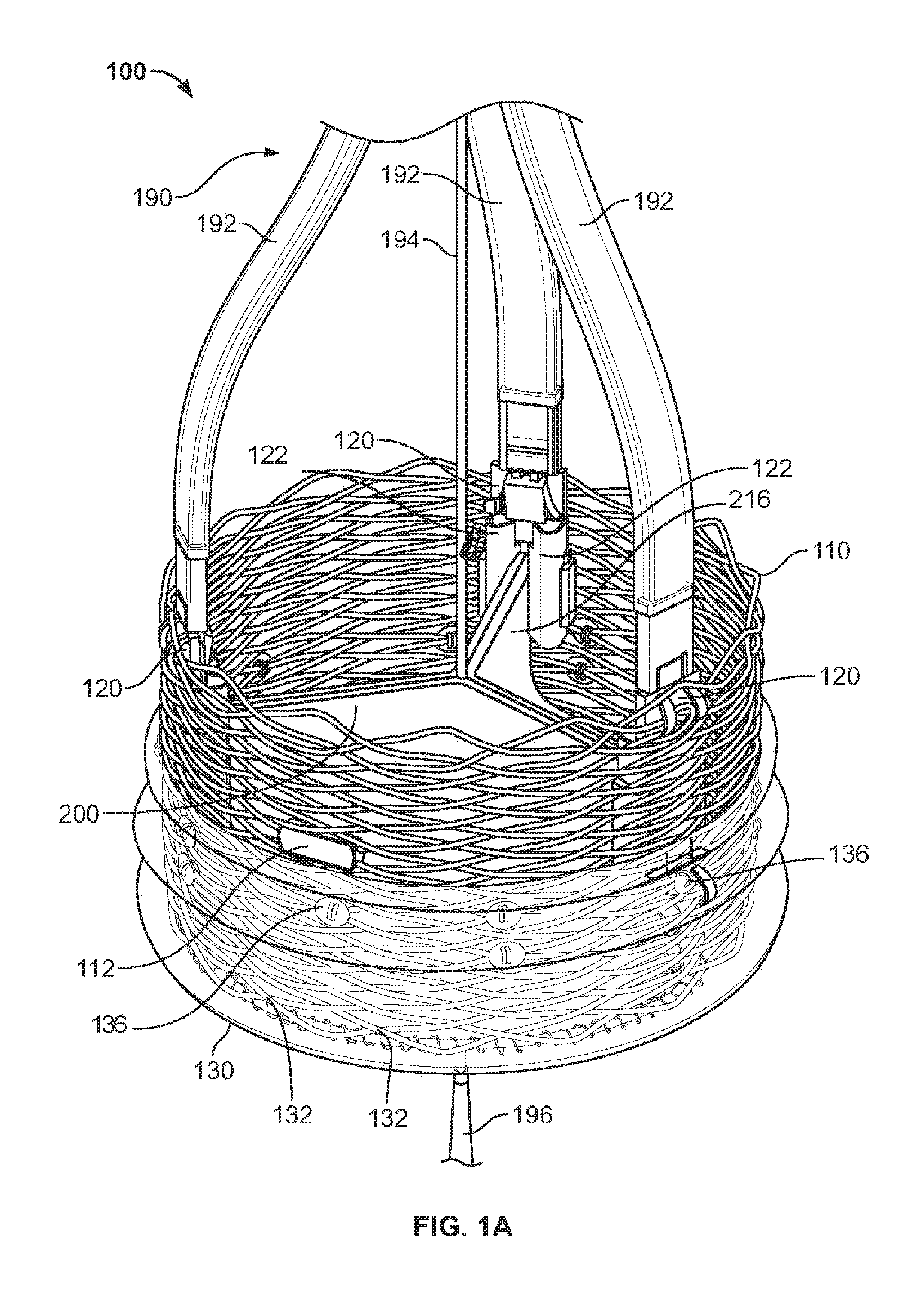
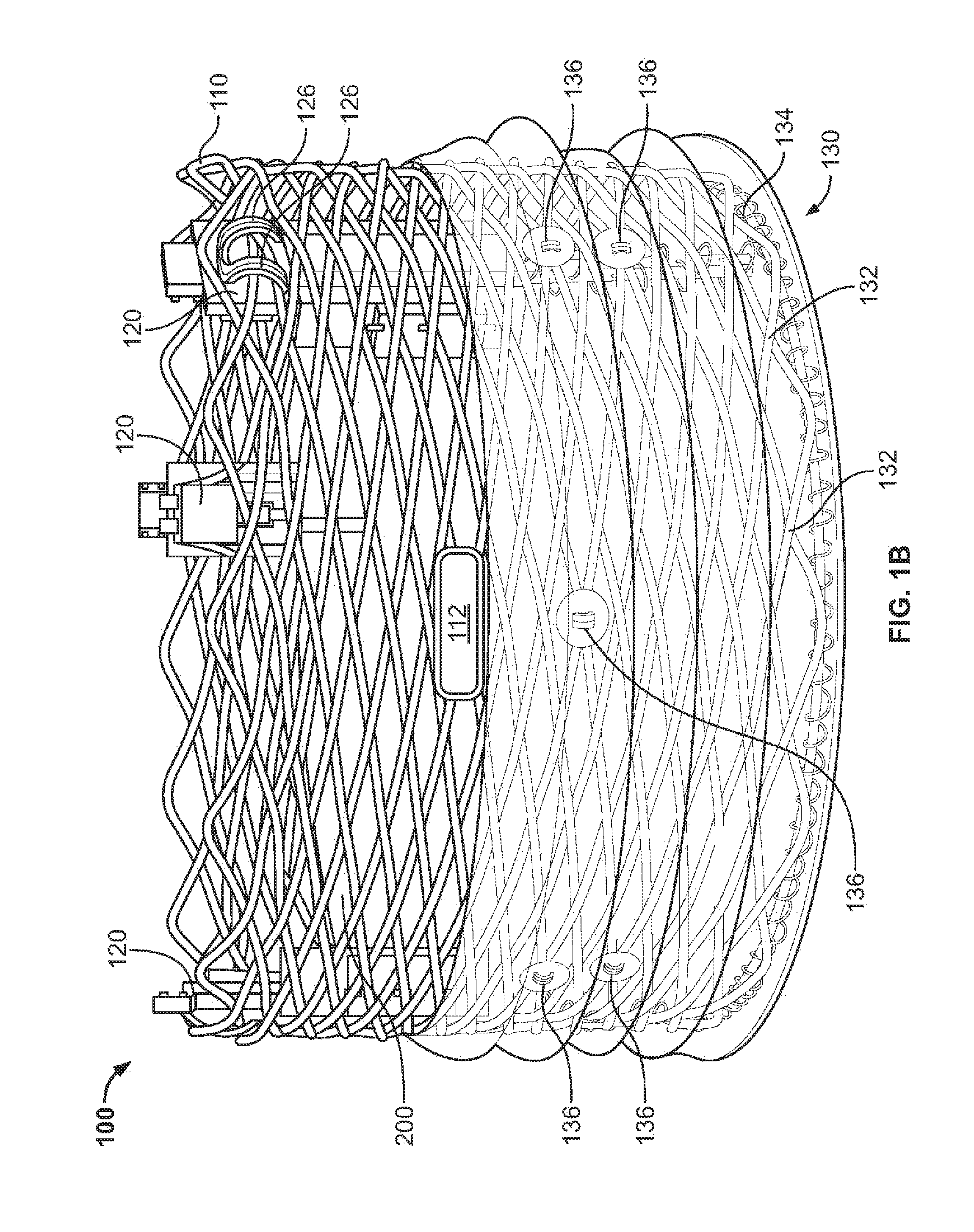
1. A prosthetic heart valve comprising: an expandable tubular member; a plurality of leaflets secured together along side edges and retained within the expandable tubular member, each leaflet having a bottom edge at a blood inflow end of the expandable tubular member and a free edge at a blood outflow end of the expandable tubular member; and a tubular seal secured to the bottom edge of each leaflet and along an outer portion of the expandable tubular member, wherein the tubular seal comprises an elastomeric polymer matrix and a plurality of non-elastic fibers retained within the matrix, and wherein the non-elastic fibers are arranged in the elastomeric polymer matrix to allow the tubular seal to stretch in axial and radial directions.
2. The prosthetic heart valve of claim 1, wherein the non-elastic fibers are part of a fabric.
3. The prosthetic heart valve of claim 2, wherein the fabric is a woven fabric.
4. The prosthetic heart valve of claim 3, wherein the woven fabric comprises fibers in a warp direction and fibers in a waft direction, wherein the fibers in both the warp direction and the waft direction are angled with respect to a central axis of the tubular seal.
5. The prosthetic heart valve of claim 3, wherein the fibers in both the warp direction and the waft direct are angled at an angle of between 5 degrees and 70 degrees with respect to the central axis of the tubular seal.
6. The prosthetic heart valve of claim 1, wherein the non-elastic fibers are uniformly dispersed throughout the elastomeric polymer matrix.
7. The prosthetic heart valve of claim 6, wherein the tubular seal has a substantially uniform thickness.
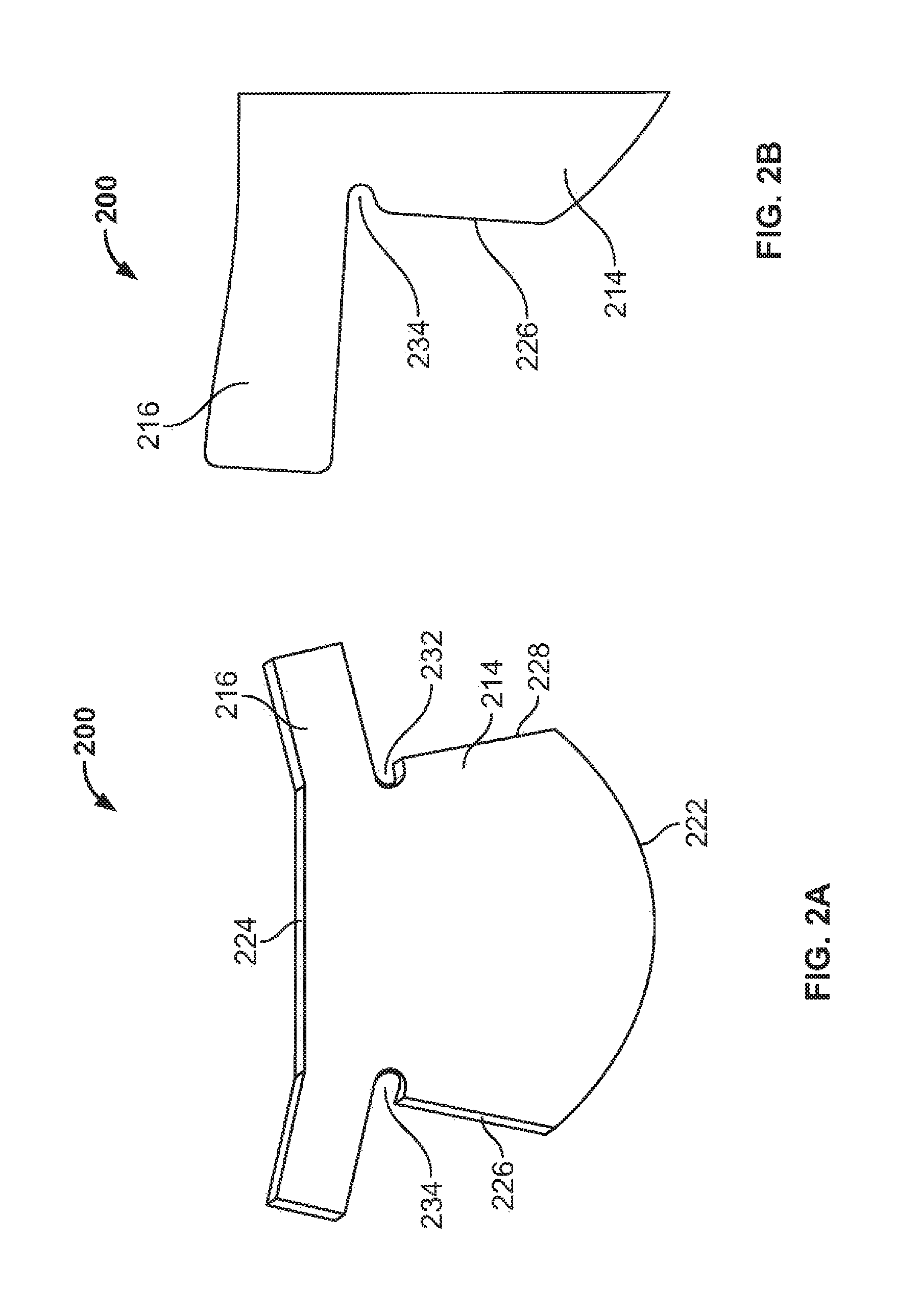
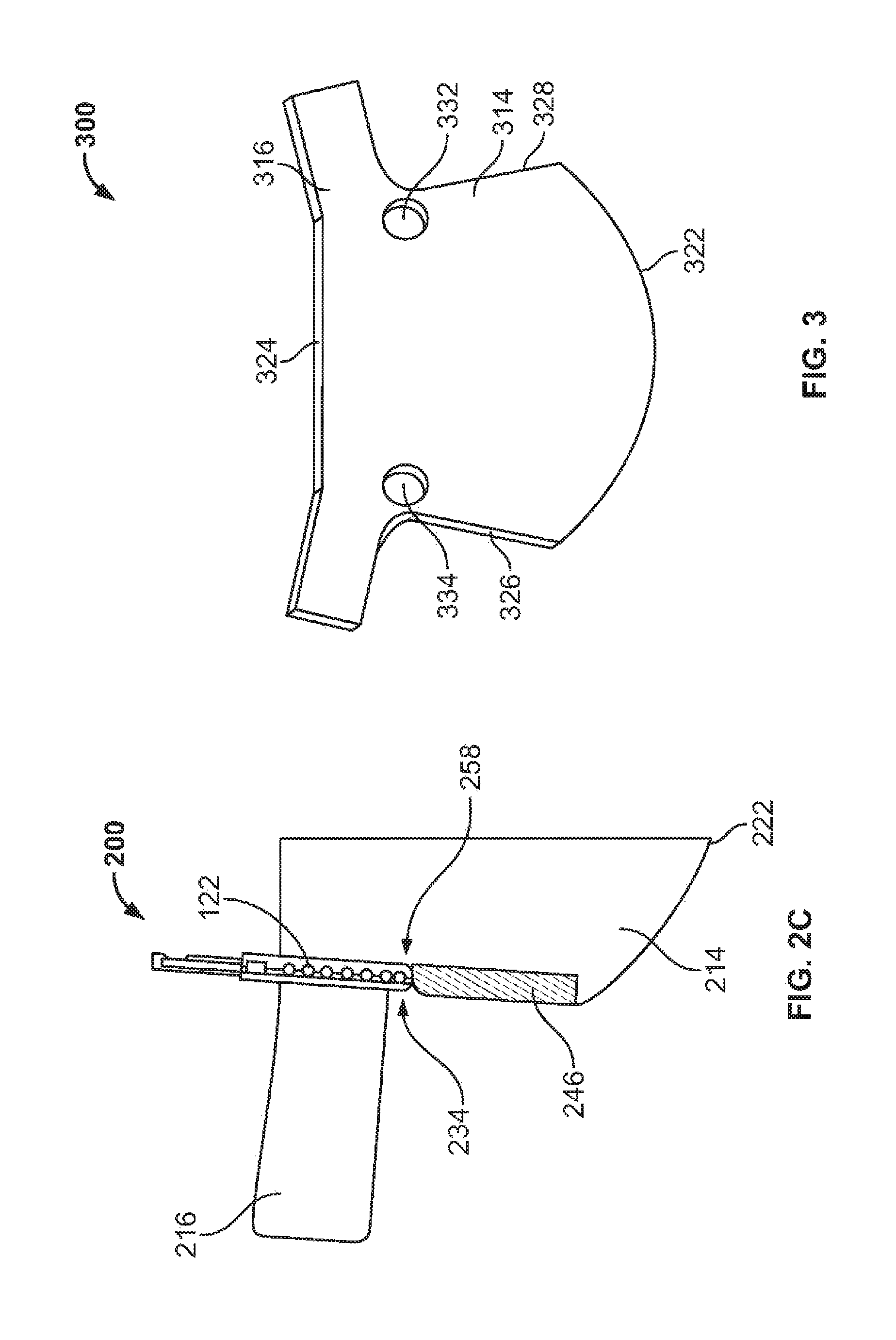
8. The prosthetic heart valve of claim 6, wherein the tubular seal comprises an outflow end region and an inflow end region, the inflow end region being a portion of the tubular seal comprising the fabric, wherein the fabric has a non-linear edge defining the interface between the inflow end region and the outflow end region.
9. The prosthetic heart valve of claim 8, wherein the non-linear edge of the fabric has a sinusoidal or scalloped shape.
10. The prosthetic heart valve of claim 8, wherein the inflow end region comprises a first substantially uniform thickness and the outflow end region comprises median thickness that is less than the first substantially uniform thickness.
11. The prosthetic heart valve of claim 8, wherein the outflow end region comprises a plurality of grommets.
12. The prosthetic heart valve of claim 1, wherein the tubular seal has a thickness range from about 30 microns to about 75 microns.
13. The prosthetic heart valve of claim 1, wherein the tubular seal has a thickness range from about 50 microns to about 120 microns.
14. A prosthetic heart valve comprising: an expandable tubular member; a plurality of leaflets secured together along side edges and retained within the expandable tubular member, each leaflet having a bottom edge at a blood inflow end of the expandable tubular member and a free edge at a blood outflow end of the expandable tubular member; and a tubular seal comprising an elastomeric polymer matrix and a fabric comprising a plurality of non-elastic fibers retained within an inflow end portion of the elastomeric polymer matrix, the inflow end portion of the tubular seal being secured to the bottom edges of the plurality of leaflets, wherein the fabric comprises a non-linear edge within the elastomeric polymer matrix.
15. The prosthetic heart valve of claim 14, wherein the non-linear edge of the fabric has a sinusoidal or scalloped shape.
16. The prosthetic heart valve of claim 14, wherein the non-elastic fibers comprise a polyester.
17. The prosthetic heart valve of claim 14, wherein the elastomeric polymer matrix comprises a first material composition and a second material composition, wherein the first material composition is different than the second material composition.
18. The prosthetic heart valve of claim 14, wherein the elastomeric polymer matrix comprises a polymer selected from polycarbonates, polyurethanes, silicones, and combinations thereof.
19. The prosthetic heart valve of claim 14, wherein the elastomeric polymer matrix comprises a polymer having a hardness ranging from 75 Shore A to 75 Shore D.
20. A prosthetic heart valve comprising: an expandable tubular member; a plurality of leaflets secured together along side edges and retained within the expandable tubular member, each leaflet having a bottom edge at a blood inflow end of the expandable tubular member; and a tubular seal comprising a polymer matrix and a fabric retained within an inflow end portion of the polymer matrix, wherein the fabric comprises a non-linear edge within the polymer matrix.
Description
FIELD
This document provides prosthetic heart valves having a tubular seal.
BACKGROUND
The human heart contains four valves: a tricuspid valve, a pulmonic valve, a mitral valve and an aortic valve. The main purpose of the valves is to maintain unimpeded forward flow through the heart and into the major blood vessels connected to the heart, for example, the pulmonary artery and the aorta. As a result of a number of disease processes, both acquired and congenital, any one of the four heart valves may malfunction and result in either stenosis (impeded forward flow) and/or backward flow (regurgitation). Either process burdens the heart and may lead to serious problems, for example, heart failure. Various procedures for fixing or replacing defective heart valves are known in the art. In some cases, artificial heart valves can be implanted in the heart of a patient to replace a diseased or damaged heart valve with a prosthetic equivalent.
Prosthetic heart valves can have a variety of designs. Two major types of prosthetic heart valves include mechanical heart valves and bioprosthetic heart valves. Mechanical heart valves can be made of synthetic materials, such as plastics or metals, while bioprosthetic heart valves can be made of biologic tissue mounted on a fabric covered plastic or metal frame. Bioprosthetic heart valves can include animal tissue, such as porcine or bovine tissue, that has been chemically treated to make the valve suitable for implantation in a human. Bioprosthetic valves do not generally require a patient to undergo anticoagulant therapy, which is typically required when using mechanical valves. As such, there is a need to further improve the design of bioprosthetic valves to retain its functionality during the life of the patient and minimize stenosis and regurgitation.
SUMMARY
Prosthetic heart valves provided herein can have a structure adapted to retain functionality during the life of the patient and to minimize stenosis and regurgitation by having an improved connection between different parts of the prosthetic heart valve.
In Example 1, a tubular seal for a prosthetic heart valve includes an elastomeric polymer matrix and a plurality of non-elastic fibers retained within the matrix. The non-elastic fibers can be arranged in the elastomeric polymer matrix to allow the tubular seal to stretch in axial and radial directions.
In Example 2, the tubular seal of Example 1, wherein the non-elastic fibers are part of a fabric.
In Example 3, the tubular seal of Example 2, wherein the fabric is a woven fabric.
In Example 4, the tubular seal of Example 3, wherein the woven fabric includes fibers in a warp direction and fibers in a waft direction, wherein the fibers in both the warp direction and the waft direction are angled with respect to a central axis of the tubular seal.
In Example 5, the tubular seal of Example 3, wherein the fibers in both the warp direction and the waft direct are angled at an angle of between 5 degrees and 70 degrees with respect to the central axis of the tubular seal.
In Example 6, the tubular seal of one of the preceding examples, wherein the non-elastic fibers are uniformly dispersed throughout the elastomeric polymer matrix.
In Example 7, the tubular seal of one of the preceding examples, wherein the tubular seal has a substantially uniform thickness.
In Example 8, the tubular seal of Examples 2-5, wherein the tubular seal comprises an outflow end region and an inflow end region, the inflow end region being a portion of the tubular seal comprising the fabric, wherein the fabric has a non-linear edge defining the interface between the inflow end region and the outflow end region.
In Example 9, the tubular seal of Example 8, wherein the non-linear edge of the fabric has a sinusoidal or scalloped shape.
In Example 10, the tubular seal of Example 8 or 9, wherein the inflow end region comprises a first substantially uniform thickness and the outflow end region comprises median thickness that is less than the first substantially uniform thickness.
In Example 11, the tubular seal of Examples 8-10, wherein the outflow end region comprises a plurality of grommets.
In Example 12, the tubular seal of one of the preceding examples, wherein the non-elastic fibers are retained within an inflow end portion of the elastomeric polymer matrix, the inflow end portion of the tubular seal are secured to the bottom edges of the plurality of leaflets, and the fabric comprises a non-linear edge within the elastomeric polymer matrix.
In Example 13, the tubular seal of Example 12, wherein the non-linear edge of the fabric has a sinusoidal or scalloped shape.
In Example 14, the tubular seal of one of the preceding examples, wherein the non-elastic fibers comprise a polyester.
In Example 15, the tubular seal of one of the preceding examples further comprising wherein an expandable tubular member and a plurality of leaflets secured together along side edges and retained within the expandable tubular member, each leaflet having a bottom edge at a blood inflow end of the expandable tubular member and a free edge at a blood outflow end of the expandable tubular member.
In Example 16, a prosthetic heart valve includes an expandable tubular member, a plurality of leaflets and a tubular seal. The plurality of leaflets can be secured together along side edges and retained within the expandable tubular member. Each leaflet can have a bottom edge at a blood inflow end of the expandable tubular member and a free edge at a blood outflow end of the expandable tubular member. The tubular seal can be secured to the bottom edge of each leaflet and along an outer portion of the expandable tubular member, wherein the tubular seal includes an elastomeric polymer matrix and a plurality of non-elastic fibers retained within the matrix, and wherein the non-elastic fibers are arranged in the elastomeric polymer matrix to allow the tubular seal to stretch in axial and radial directions.
In Example 17, the prosthetic heart valve of Example 16, wherein the non-elastic fibers are part of a fabric.
In Example 18, the prosthetic heart valve of Example 17, wherein the fabric is a woven fabric.
In Example 19, the prosthetic heart valve of Example 18, wherein the woven fabric comprises fibers in a warp direction and fibers in a waft direction, wherein the fibers in both the warp direction and the waft direction are angled with respect to a central axis of the tubular seal.
In Example 20, the prosthetic heart valve of Example 18, wherein the fibers in both the warp direction and the waft direct are angled at an angle of between 5 degrees and 70 degrees with respect to the central axis of the tubular seal.
In Example 21, the prosthetic heart valve of Example 16, wherein the non-elastic fibers are uniformly dispersed throughout the elastomeric polymer matrix.
In Example 22, the prosthetic heart valve of Example 21, wherein the tubular seal has a substantially uniform thickness.
In Example 23, the prosthetic heart valve of Example 21, wherein the tubular seal comprises an outflow end region and an inflow end region, the inflow end region being a portion of the tubular seal comprising the fabric, wherein the fabric has a non-linear edge defining the interface between the inflow end region and the outflow end region.
In Example 24, the prosthetic heart valve of Example 23, wherein the non-linear edge of the fabric has a sinusoidal or scalloped shape.
In Example 25, the prosthetic heart valve of Example 23, wherein the inflow end region comprises a first substantially uniform thickness and the outflow end region comprises median thickness that is less than the first substantially uniform thickness.
In Example 26, the prosthetic heart valve of Example 23, wherein the outflow end region comprises a plurality of grommets.
In Example 27, the prosthetic heart valve of Example 16, wherein the tubular seal has a thickness range from about 30 microns to about 75 microns.
In Example 28, the prosthetic heart valve of Example 16, wherein the tubular seal has a thickness range from about 50 microns to about 120 microns.
In Example 29, a prosthetic heart valve includes an expandable tubular member, a plurality of leaflets and a tubular seal. The plurality of leaflets can be secured together along side edges and retained within the expandable tubular member, each leaflet having a bottom edge at a blood inflow end of the expandable tubular member and a free edge at a blood outflow end of the expandable tubular member. The tubular seal can include an elastomeric polymer matrix and a fabric can include a plurality of non-elastic fibers retained within an inflow end portion of the elastomeric polymer matrix. The inflow end portion of the tubular seal can be secured to the bottom edges of the plurality of leaflets, wherein the fabric includes a non-linear edge within the elastomeric polymer matrix.
In Example 30, the prosthetic heart valve of Example 29, wherein the non-linear edge of the fabric has a sinusoidal or scalloped shape.
In Example 31, the prosthetic heart valve of Example 29, wherein the non-elastic fibers comprise a polyester.
In Example 32, the prosthetic heart valve of Example 29, wherein the elastomeric polymer matrix comprises a first material composition and a second material composition, wherein the first material composition is different than the second material composition.
In Example 33, the prosthetic heart valve of Example 29, wherein the elastomeric polymer matrix comprises a polymer selected from polycarbonates, polyurethanes, silicones, and combinations thereof.
In Example 34, the prosthetic heart valve of Example 29, wherein the elastomeric polymer matrix comprises a polymer having a hardness ranging from 75 Shore A to 75 Shore D.
In Example 35, a prosthetic heart valve includes an expandable tubular member, a plurality of leaflets and a tubular seal. The plurality of leaflets can be secured together along side edges and retained within the expandable tubular member, each leaflet having a bottom edge at a blood inflow end of the expandable tubular member. The tubular seal can include a polymer matrix and a fabric retained within an inflow end portion of the polymer matrix, wherein the fabric includes a non-linear edge within the polymer matrix.
Prosthetic heart valves provided herein can additionally have a reduced unexpanded profile. In some cases, prosthetic heart valves provided herein include a plurality of anchor elements. In some cases, anchor elements can be secured to an expandable tubular member. In some cases, the expandable tubular member can be a braided stent. In some cases, prosthetic heart valves provided herein include three or more leaflets. In some cases, the leaflets can have a body portion and sleeve portions one or both sides. In some cases, sides of the body portions can be secured together and sleeve portions secured to anchor elements (e.g., anchor elements attached to a braided stent). In some cases, prosthetic heart valves provided herein can include a tubular seal. In some cases, the tubular seal can be secured to bottom edges of body portions of the leaflets. In some cases, the seal can be secured to a blood inlet side of an expandable member.
The details of one or more embodiments of the invention are set forth in the accompanying drawings and the description below. Other features, objects, and advantages of the invention will be apparent from the description and drawings, and from the claims.
DESCRIPTION OF DRAWINGS
FIGS. 1A-1H illustrate an exemplary prosthetic heart valve and an exemplary deployment device provided herein. FIG. 1A is a perspective view of the heart valve connected to the deployment device. FIG. 1B is a side view of the exemplary prosthetic heart valve. FIGS. 1C-1H illustrate how the exemplary heart valve provided herein can be delivered by the deployment device.
FIGS. 2A-2C illustrates an exemplary leaflet, which can be used in prosthetic heart valves provided herein. FIG. 2A illustrates a rounded notch in a leaflet where a leaflet can be secured to an adjacent leaflet. FIGS. 2B and 2C illustrate a portion of an exemplary leaflet for prosthetic heart valves. FIG. 2B depicts the rounded notch in an armpit of a leaflet. FIG. 2C depicts attachment elements in the armpit of the leaflet.
FIG. 3 illustrates another exemplary leaflet, which can be used in prosthetic heart valves provided herein. FIG. 3 depicts apertures in a body of the exemplary leaflet.
FIGS. 4A-4G illustrate how adjacent leaflets can be stitched together in prosthetic heart valves provided herein.
FIGS. 5A-5C illustrate a cross stich provided herein for connecting a seal to a braided stent in an exemplary prosthetic heart valve provided herein. FIG. 5A shows a front view of a seal having apertures and stitch patterns used for securing the seal to the braided stent. FIG. 5B depicts a close up view of a cross stitch and a portion of a circumferential stitch used for securing the seal to the braided stent. FIG. 5C depicts a cross-sectional view showing the cross stitch and a portion of the circumferential stitch.
FIG. 6 depicts an apparatus that can be used to form a tubular seal provided herein.
FIGS. 7A-7E depict exemplary tubular seals having a fabric positioned within a matrix that can be used in a prosthetic heart valve provided herein.
Like reference symbols in the various drawings indicate like elements.
DETAILED DESCRIPTION
FIGS. 1A and 1B illustrate an exemplary prosthetic heart valve 100 provided herein. FIGS. 1C-1H depict how prosthetic heart valve 100 is deployed. FIG. 1A is a perspective view of prosthetic heart valve 100 connected to a deployment device 190.
FIG. 1B is a side view of prosthetic heart valve 100. As shown, prosthetic heart valve 100 includes an expandable member 110, three leaflets 200, three anchor elements 120 that secure sleeve portions 216 of leaflets 200 to expandable member 110, and a tubular seal 130 secured around a blood inflow end of prosthetic heart valve 100. Anchor elements 120 can include post leg compression elements 122 and clamping support structures 126 adapted to provide support along opposite sides of the sleeve portions 216. Expandable member 110 in FIGS. 1A-1D is a braided stent, which is adapted to transition between a restricted state having a smaller diameter and an expanded state having a larger diameter. Expandable member 110 can be self-expanding, mechanically expanded, or a combination thereof.
FIGS. 1C-1H depict how an exemplary heart valve delivery system can deliver the prosthetic heart valve provided herein. As shown in FIGS. 1C-1H, prosthetic heart valve 100 can be deployed using a heart valve delivery system 180. System 180 can include a sheath 182 for retaining the prosthetic heart valve 100 with the expandable member 110 in a restricted state. As discussed above, tubular seals provided herein can have a uniform thickness or a thickness that has a non-linear interface between an inflow end portion and an outflow end portion to provide a transition zone between a thinner outflow end portion to the thicker inflow end portion to facilitate loading of prosthetic heart valve 100 into sheath 182. For example, a substantially uniform thickness or a transition zone can reduce the probability for sections of the tubular seal to catch on an outer rim of sheath 182 during loading of prosthetic heart valve 100 in a restricted state. Additionally, tubular seals provided herein can allow for radial and/or axial expansion of the tubular seal in portions including non-elastic fibers, accordingly, a tubular seal used in prosthetic heart valves provided herein can have a non-expanded diameter that expands to the predetermined outer diameter of the expandable member and that stretches to an axially elongated but radially restricted configuration when the prosthetic heart valve is in a restricted state to further reduce the profile of the prosthetic heart valve within the sheath.
Within sheath 182, anchor elements 120 (FIGS. 1A and 1B) can be connected to pushing prongs 192 and a pull line 194 can be connected to a nose cap 196, or end cap, which is positioned at the end of the sheath 182. As shown in FIG. 1A, the pull line 194 can extend through expandable member 110 and through the valve opening between the leaflets 200. As shown by FIGS. 1D-1H, once a distal end of sheath 182 is delivered through the circulatory system to an appropriate location (e.g., within the heart), prosthetic heart valve 100 can be deployed. By advancing pushing prongs 192 and pull line 194 relative to sheath 182, prosthetic heart valve 100 can be pushed out of the sheath 182. In some cases, expandable member 110 can self-expand upon exiting sheath 182. In some cases, expandable member 110 can self-expand to a first intermediate diameter, and system 180 can mechanically expand expandable member 110 to a larger deployment diameter. For example, anchor elements 120 can include a locking mechanism to clip a portion of expandable member when the expandable member 110 is expanded to a predetermined locking diameter. In some cases, system 180 can mechanically expand expandable member 110 to a predetermined locking diameter. In some cases, system 180 can compress expandable member 110 between pushing prongs 192 and nose cap 196 by moving pull line 194 relative to pushing prongs 192. The predetermined locking diameter can be adapted to set the diameter of the prosthetic heart valve 100 during implantation. After prosthetic heart valve 100 is set, system 180 can move pull line 194 and nose cap 196 relative to pushing prongs 192 to move the end cap through the opening between leaflets 200 in prosthetic heart valve 100. Pushing prongs 192 can then be retracted from anchor elements 120 and retracted into sheath 182. In some cases, pushing prongs 192 can include a shape member material adapted to help radially expand expandable member 110 as the expandable member 110 exits sheath 182. A control handle 188 can be used to control the relative movements of sheath 182, pushing prongs 192, and pull wire 194. Prosthetic heart valves provided herein can be adapted to mitigate damage that might otherwise occur to valves during delivery and implantation.
In some cases, one or more radiopaque markers can be secured to prosthetic heart valves provided herein. As shown in FIGS. 1A and 1B, expandable member 110 includes a radiopaque marker 112. Any suitable radiopaque material (such as platinum, palladium, gold, tantalum, or alloys thereof) can be used as the radiopaque material in radiopaque marker 112. One or more radiopaque markers can be used with an imaging system to help a physician ensure that a valve is set in an appropriate location. In some cases, prosthetic heart valves provided herein include at least three radiopaque markers.
As shown in FIG. 1A, prosthetic heart valve 100 can include a plurality of leaflets 200. In some cases, as shown, prosthetic heart valve 100 includes three leaflets 200. In some cases, prosthetic heart valves provided herein can have any suitable number of leaflets, such as two, three, four, five, or more leaflets. In some cases, leaflets 200 are secured to one another. In some cases, leaflets 200 can be secured to one another via a plurality of sutures. Leaflets 200 can be sutured along side edges of a body portion of each leaflet. In some cases, prosthetic heart valves provide herein can include a single line of sutures, which can be adapted to minimize leaks, minimize the width of a seam, and/or minimize the profile of a replacement heart valve during percutaneous insertion. In some cases, prosthetic heart valves provide herein can include multiple lines of sutures.
Expandable member 110 can have any suitable structure, arrangement, or material. In some cases, expandable member 110 can include a braided wire stent. For example, U.S. Publication Number 2005/0143809, titled, "Methods and Apparatus for Endovascularly Replacing a Heart Valve," and filed on Nov. 5, 2004, which is herein incorporated by reference for its disclosure of possible structures and materials for a braided wire stent, discloses a braided wire stent. In some cases, expandable member 110 includes a shape memory material (e.g., a nickel-titanium alloy or a cobalt-chromium alloy).
Referring to FIGS. 2A-2C, a leaflet 200 can include a body portion 214 and sleeve portions 216. In some cases, the body portion 214 has a bottom edge 222, a first side edge 226, a second side edge 228, and a free edge 224. Leaflet 200 further includes a front (i.e., the side that blood flows toward), a back (i.e., the side that blood flows away from), a first side adjacent to the first side edge 226, and a second side adjacent to the second side edge 228. In some cases, the front of the leaflet 200 has a different texture than the back. In some cases, for example, the back of the leaflet may be prone to calcium build due to its cusp-shaped surface, therefore it can be beneficial to have a textured surface on the back of the leaflet to mitigate valve calcification issues. In some cases, however, having the back with a non-textured surface can mitigate calcification issues. In some cases, the leaflet 200 is made from tissue obtained from an animal, e.g., a pig or a cow. In some cases, leaflet 200 is made from bovine pericardium. Leaflets 200 can also be made from a synthetic material. Leaflets 200 can be assembled into a heart valve by aligning the opposite side regions of at least two adjacent leaflets 200 and stitching the leaflets 200 together along stitch line 246, as shown in FIG. 2C.
As shown in FIGS. 2A-2C, a prosthetic heart valve can include at least one leaflet 200 having a body portion 214 and two opposite sleeve portions 216. The body portion 214 can be defined by two side edges 226, 228 adjacent each sleeve portion 216. The at least one leaflet 200 can define at least one notch 232, 234 between at least one of the two side edges 226, 228 and the adjacent sleeve portion 216. In other words, each notch 232, 234 can be located along the side edges 228, 226 at a location that is adjacent to the sleeve portions 216, at an armpit of the leaflet 200, as depicted in FIGS. 2A and 2B. In some cases, leaflet 200 can define a notch 232, 234 generally along the side edges 228, 226. In some cases, a notch 232, 234 can be defined along the sleeve portion 216. In some cases, multiple notches 232, 234 can be located along the sleeve portion 216 or one of the side edges 228, 226, and/or at the armpit of the leaflet 200.
As shown in FIG. 2A and 2B, the body portion 214 of the leaflet can have a conical frustum shape defined by a bottom edge 222, the first side edge 226, the second side edge 228, and a free edge 224. In some cases, other suitable shapes for the body portion can be contemplated, for example, a generally square, rectangular, triangular or trapezoidal shaped body portion.
The sleeve portions, as shown in FIGS. 2A-2C, can extend outwardly from the body portion of the leaflet 200. Each sleeve portion may be angled away from free edge of the body portion. Sleeve portions can be generally rectangular-shaped extensions with lateral ends. In some cases, the sleeve portions can have rounded ends.
Still referring to FIGS. 2A-2C, notches 232, 234 can be generally U-shaped. Other suitable notch shapes can include, but are not limited to, a V-shaped, Z-shaped, rectangular-shaped and an oval-shaped notch. Notches can also have rounded edges to smooth the transition between a notch and the side edges 228, 226 of the leaflet 200. Notches 232, 234 can have a length dimension that can range from about 0.02 inches to about 0.20 inches (or from about 0.5 millimeters (mm) to about 4 mm).
Referring to FIG. 2C, notches 232, 234 can be shaped and sized to accommodate attachment of post leg compression elements 122. Post leg compression elements 122 can be a part of anchor elements 120 (shown in FIGS. 1A and 1B) that compress and restrain sleeve portions 216 along the same line as the stitch line 246. A suture 258 can be used to apply an appropriate and consistent compressive force between the post leg compression elements 122 in order to prevent leakage through sleeve portions 216 of the leaflets 200. Sutures that pierce the body portion 214 at or near the armpit of the leaflet, however, can pull, stretch and abrade the surrounding adjacent tissue, creating stress concentrations at or near the armpit of the leaflet. Stress concentrators can result in tears forming in the leaflet material. Using notches 232 and 234 and post leg compression elements 122, however, can minimize potential heart valve tearing caused by sutures at or near the armpit location. Notches 232, 234 can be positioned proximate to the post leg compression elements near the armpit of the leaflet, e.g., between at least one of the two side edges 226, 228 and the adjacent sleeve portion 216, to create enlarged openings that suture 258 can pass therethrough without pulling or stretching the adjacent tissue. Accordingly, a notched leaflet 200 can improve valve opening capabilities and the reliability of prosthetic heart valves provided herein.
FIG. 3 illustrates another exemplary leaflet, which can be used in prosthetic heart valves provided herein. As shown in FIG. 3, leaflet 300 can include a body portion 314 and at least two opposite sleeve portions 316. The body portion 314 can be defined by at least two side edges 326, 328 adjacent each sleeve portion 316. Leaflet 300 can define two apertures 332 and 334. Each aperture 332, 334 can be positioned adjacent the side edges 326, 328 and an adjacent sleeve portion 316. Each aperture 332, 334 can be adapted to secure one leaflet to an adjacent leaflet.
In some cases, the body portion 314 has a bottom edge 322, a first side edge 326, a second side edge 328, and a free edge 324. Leaflet 300 further includes a front, a back, a first side adjacent to the first side edge 326, and a second side adjacent to the second side edge 328. In some cases, the front of the leaflet 300 has a different texture than the back. In some cases, this occurs where the leaflet 300 is made from pig, cow, or other natural animal tissue. In some cases, leaflet 300 is made from bovine pericardium. Leaflets 300 can also be made from a synthetic material. Leaflets 300 can be assembled into a heart valve by aligning the opposite side regions of at least two adjacent leaflets 300 and stitching the leaflets 300 together along stitch line 246, as shown in FIG. 2C.
As shown in FIG. 3, leaflet 300 defines apertures 332 and 334 adjacent the side edges 328, 326 and adjacent the sleeve portions 316. Apertures 332 and 334 can be generally circular in shape. Other suitable aperture shapes can include, for example, a rectangular, an oval, a triangular, or a diamond shape. In some cases, apertures 332, 334 can have a length dimension or a diameter from about 0.02 inches to about 0.20 inches (or from about 0.5 mm to about 4 mm). In some cases, one or more apertures 332, 334 can be located in the side edges 328, 326 and/or the sleeve portions 316 of the leaflet 300. In some cases, multiple apertures can be located in a region that is adjacent to the side edges 328, 326 and the sleeve portions 316.
Apertures 332, 334 in the leaflets 300 can allow one leaflet to be secured to an adjacent leaflet. Similar to the notches discussed above, apertures 332 and 334 can be shaped and sized to accommodate attachment of post leg compression elements 122. Referring back to FIGS. 1A and 1B post leg compression elements 122 can be a part of anchor elements 120 that compress and restrain sleeve portions 216 along the same line as the stitch line 246. A suture 258 can be used to apply an appropriate and consistent compressive force between the post leg compression elements 122 in order to prevent leakage through sleeve portions 216 of the leaflets 200. As already discussed herein, sutures that pierce the body portion 214 at or near the armpit of the leaflet can create stress concentrations at or near the armpit of the leaflet that may result in tearing. Apertures 332 and 334 and post leg compression elements 122, however, can minimize this potential tearing caused by sutures near the armpit location. Apertures 332, 334 can be positioned proximate to the post leg compression elements near the armpit location to create enlarged openings that suture 258 can pass therethrough without pulling or stretching the adjacent tissue. Accordingly, leaflets 300 used in prosthetic heart valves provided herein can improve the reliability of prosthetic heart valves provided herein.
FIGS. 4A-4G depict how leaflets 200 can be connected (or jointed) with an improved stitch discussed herein. As shown, stitch 446 can be a single continuous line stitch traveling along a stitch line in a forward direction and back in a reverse direction. In some cases, stitch 446 can run along a leaflet from a bottom edge to a side edge of the leaflet (e.g., bottom edge 222 to side edge 226 of leaflet 200 in FIG. 2A-2B). In some cases, stitch 446 can run from a side edge to a notch of a leaflet (e.g., side edge 226 to notch 234 of leaflet 200 in FIG. 2A-2B).
As shown in FIGS. 4D-4G; stitch 446 can include a plurality of perpendicular loop segments 434 extending through an aperture in the two leaflets, around outer side edges of the two attached leaflets, and back through the aperture. Stitch 446 can include a plurality of parallel segments 436 extending between adjacent apertures along the stitch line. Stitch 446 can include two perpendicular loop segments 434 extending through apertures formed in the stitch line. In some cases, a first perpendicular loop segment 434 for a first aperture in the stitch line is formed when the stitch is formed in the forward direction and a second perpendicular loop segment 434 for the first aperture is formed in the reverse direction. In some cases, parallel segments 436 made in a forward direction alternate between opposite sides of the two leaflets between each aperture in the stitch line. In some cases, parallel segments 436 made in a reverse direction are formed on an opposite side of the two leaflets from parallel segments 436 made in a forward direction. In some cases, opposite parallel segments 436 made in the forward and reverse directions can provide a continuous compressive force along the entire length of the stitch line. Perpendicular loop segments 434 can provide compressive force to reinforce a seal formed between the two leaflets along the stitch line.
Stitch 446 can include any appropriate number of perpendicular loop segments formed through any appropriate number of apertures. As shown, stitch 446 includes six perpendicular loop segments formed through six apertures (two perpendicular loop segments per aperture). In some cases, stitch 446 can include up to twelve perpendicular loop segments formed through six or more apertures. In some cases, a stitch connecting side edge segments of leaflets can be formed using between 3 and 20 apertures and include between 3 and 40 perpendicular loop segments. In some cases, apertures can be positioned from about 0.008 inches to about 0.4 inches apart (about 0.2 mm to about 10 mm apart). In some cases, apertures can be positioned from about 0.008 inches to about 0.4 inches (about 0.2 mm to about 10 mm) away from the side edges of the leaflets.
Stitch 446 can be formed in a process depicted in FIGS. 4A-4G As shown in FIG. 4A, a thread needle 410 can be passed through aligned leaflet side edges 226a and 226b to create a first aperture at a location near bottom edges 222, e.g., a location approximately 1 mm from the bottom edges 222. The leaflet side edges 226a and 226b can be retained in a desired configuration by clamping the leaflets between clamp sides 422 and 424. Needle 410 pulls a leading end 431 of a thread 432 through the first aperture. As shown in FIG. 4B, needle 410 can then form a second aperture adjacent to the first aperture along the stitch line (towards the leaflet sleeve portion) about 0.5 mm away from the first aperture to pull leading end 431 of thread 432 through the second aperture to form a first parallel segment. As shown in FIG. 4C, a perpendicular loop segment 434 can be made by guiding needle 410 around the leaflet side edges and re-enter the second aperture from a backside. Thread 432 can be pulled through the second aperture until it sits firmly against the leaflet material (e.g., leaflet pericardium tissue). FIG. 4D shows a second parallel segment, which can be made by pushing needle 410 through leaflet tissue along the stitch line to form a third aperture approximately 1 mm from the second aperture (towards the sleeve segments of the leaflet). As shown in FIG. 4E, a second perpendicular loop segment 434 can be formed by again having needle 410 loop around the leaflet side edges and reenter the third aperture through the backside. This is repeated up to notch 234 to form a total of six parallel segments 436 and six perpendicular loop segments 434 in a forward direction, as shown in FIG. 4F. The stitch pattern can then be repeated in a reverse direction towards the bottom edges 222 of the leaflets through the previously formed apertures. Accordingly, each aperture can include two perpendicular loop segments 434 and parallel segments on the opposite sides can be formed from the parallel segments that were created in the forward direction, as shown in FIG. 4G The method and stitches depicted in FIGS. 4A-4G can be applicable to leaflets 200, 300 discussed herein.
Stitch 446 and other stitches provided herein can improve the reliability of a seal formed along a stitch line, create fewer apertures through the leaflets, and simplify the stitching operation. Having fewer apertures can help minimize the occurrence of blood leakage through the apertures. The single continuous line of stitch 446 using a single row of apertures can minimize a width of a side edge portion needed to form a continuous seal along the side edges of the leaflets, thus providing a reduced restricted profile for prosthetic heart valves provided herein. For example, U.S. Pat. No. 8,778,020 describes a variety of ways that leaflets can be sutured together using combinations of whip stitches and running stitches, but these stitches require additional apertures and multiple lines. Perpendicular loop segments 434 can stitch a plurality of leaflets together, similar to the whip stitches discussed in U.S. Pat. No. 8,778,020. Parallel segments 436 can secure valve leaflets to one another, similar to the running stitches discussed in U.S. Pat. No. 8,778,020. Although stitch 446 can provide an improved attachment between side edges of leaflets in prosthetic heart valves provided herein, some embodiments of prosthetic heart valves provided herein can use other stitch patterns, such as those described in U.S. Pat. No. 8,778,020, which is hereby incorporated by reference.
Important characteristics of the thread can include, but are not limited to, tensile strength, abrasion resistance and creep rupture resistance characteristics that allow the device to be delivered and implanted into a human anatomy. The thread used for suturing together portions of the heart valve, e.g., sides edges of the leaflets, can be composed of biocompatible materials that include, but are not limited to, polyethylenes such as ultra high molecular weight polyethylene (UHMWPE), polyesters (PET), and combinations thereof.
Referring back to FIGS. 1A and 1B, prosthetic heart valve 100 can include a tubular seal 130. Tubular seal 130 can be secured to bottom edges 222 (FIG. 2A) of the body portion 214 of at least one leaflet 200 by a circumferential running stitch 134 within prosthetic heart valve 100. Tubular seal 130 can be secured to expandable tubular member 110 by fasteners 136 and extended around the outside of expandable tubular member 110 to provide a seal that minimizes blood leakage around the leaflets 200 of an implanted prosthetic heart valve 100. The structure and materials of tubular seal 130 are discussed below in reference to FIGS. 6 and 7A-7E.
Referring to FIGS. 5A-5C, an improved tubular seal stitching pattern can include a cross stitch 132 between tubular seal 130 and expandable member 110. FIGS. 5A-5C illustrate how the tubular seal 130 can be secured to the expandable member 110, e.g., a braided stent, by a plurality of cross stitches connecting the tubular seal 130 to a pair of overlapping wire members of the braided stent. As shown in FIGS. 1A, 1B and 5A-5C, expandable member 110 can be a braided stent including one or more wires having a first set of segments 114 extending helically in a first direction and a second set of segments 116 extending helically in a second direction such that the first set of segments 114 cross the second set of segments 116 at intersection points 118. As shown, one or more wires can have inflow crowns 115 at an end of the braided stent where the wires transition from first segments 114 to second segments 116. In some cases, cross stitches 132 secure tubular seal 130 at an intersection 118 to two crossing segments 114, 116 of the braided stent. A separate circumferential running stitch 134 can be inserted into preformed apertures 133 to secure the adaptive seal to bottom edges 222 of leaflets 200 shown in FIGS. 2A and 2C. Cross-stitches around the intersections 118 can increase the strength of an attachment of tubular seal 130 to the expandable member 110 while also allowing for improved load transfer to the expandable member 110. In some cases, the cross stitches secure tubular seal 130 at intersections 118 located immediately above (proximal) the inflow crowns 115. Cross stitches 132 can be formed by passing two stitches 132a, 132b of a suture in orthogonal directions over the intersections 118 and through the tubular seal 130. In some cases, preformed apertures 131 for cross stitch 132 can be formed in the tubular seal 130. In some cases, a portion of the tubular seal 130 that is sutured by cross stitch 132 includes an internal fabric, such as those discussed below. Each cross stitch 132 can be knotted independently. As shown in FIG. 5C, cross stitches 132 each include a separate knot 137. Additionally, cross stitches 132 can be arranged to not pass through leaflets 200. Cross stitches 132 can be repeated at a plurality of intersections 118 (FIG. 5A) circumferentially around an inflow end of a prosthetic heart valve provided herein such that an entire circumference of tubular seal 130 is securely attached. In some cases, each intersection 118 immediately adjacent to inflow crowns 115 is sutured to tubular seal 130 via a cross stitch provided herein. The tubular seal stitching pattern provided herein can increase the strength of the attachment between the tubular seal 130 and the expandable member 110 while also allowing for improved load transfer to the expandable member 110 through the use of the plurality of cross stitches.
Tubular seal 130 can have any suitable structure. In some cases, tubular seal 130 can include an elastic material. In some cases, tubular seal 130 can include one or more layers of an elastomeric polymer. In some cases, tubular seal 130 can include a polycarbonate, polyurethane, silicone, polytetrafluoroethylene (PTFE), or a combination thereof. Other suitable materials include, but are not limited to, natural and synthetic rubbers, including cis-1,4-polyisoprene rubber, styrene/butadierie copolymers, polybutadiene rubber, styrene/isoprene/butadiene rubber, butyl rubber, halobutyl rubber; polyurethane elastomers, including elastomers based on both aromatic and aliphatic isocyanates; flexible polyolefins, including flexible polyethylene and polypropylene homopolymers and copolymers; styrenic thermoplastic elastomers; polyamide elastomers; polyamide-ether elastomers; ester-ether or ester-ester elastomers; flexible ionomers; thermoplastic vulcanizates; flexible poly(vinyl chloride) homopolymers and copolymers; flexible acrylic polymers; and blends and alloys of these, such as poly(vinyl chloride) alloys like poly(vinyl chloride)-polyurethane alloys. In some cases, tubular seal 130 can include an aliphatic polycarbonate-based thermoplastic urethane. In some cases, tubular seal 130 can include an elastomeric polymer having a hardness ranging from 3.07 MPa to 9.9 MPa, or a durometer ranging from 75 Shore A to 75 Shore D using ASTM standard D2240 in force on Jan. 1, 2014. In some cases, tubular seal 130 can include a polymeric material having the mechanical properties shown in Table I below. Notably, all of the listed ASTM standards refers to the standard in force on Jan. 1, 2014.
TABLE-US-00001 TABLE I ASTM Standard Durometer Range 75 Shore A-75 Shore D D2240 Available Specific Gravity 1.10-1.14 D792 Melt Flow 2-26 g/10 min (205.degree. C./3.26 kg) D1238 MECHANICAL ASTM PROPERTY RANGES Standard Durometer 75A-B20 55D 75D 75D Ultimate Tensile 400-9000 5000-10000 3000-8000 D638 Strength (psi) Tensile (psi) @50% elongation 350-650 1500-1800 3000-8000 D638 @100% elongation 550-850 1800-2200 3000-8000 D638 @200% elongation 600-1200 2800-4200 D638 @300% elongation 1200-2000 4200-10000 D630 Ultimate Elongation 350-750 200-400 100-300 D638 (%)
In some cases, referring back to FIG. 1A, tubular seal 130 can include attachment structures to improve the attachment of the tubular seal 130 to leaflets 200 and/or expandable member 110.
In some cases, as shown in FIG. 7A, a tubular seal 730 can include an inflow end section 740 and an outflow end section 750. The inflow end section 740 can include a fabric embedded within elastomeric material and the outflow end section 750 can include a plurality of grommets 732. The fabric of inflow end section 740 can be a woven material. In some cases, the fabric can have warp threads and/or weft threads. The fabric is composed of fibers having an average thread diameter from about 0.00002 inches to about 0.002 inches (or from about 0.5 microns to about 50 microns), more preferably from about 0.0008 inches to about 0.002 inches (or from about 20 micron to about 40 microns). In some cases, more preferably, the fabric is composed of fibers having a thread diameter of about 0.0011 inches (about 27 microns).
In some cases, the fabric can include non-elastomeric fibers. Suitable non-elastomeric fiber materials include, but are not limited to, polyolefins, polyesters such as PES 38/31 manufactured by SaatiTech, and polyamides. More particularly, the polyolefins may be, for example, one or more of polyethylene, polypropylene, polybutene, ethylene copolymers, propylene copolymers, and butene copolymers. Because the fabric can include non-elastic fibers, inflow end section 740 and outflow end section 750 can have different overall elastic properties. In some cases, tubular seal 730 can be used as a tubular seal 130 of prosthetic heart valve 100, as previously shown in FIG. 1A. In some cases, tubular seal 730 can be used in other prosthetic heart valves provided herein.
As shown in FIGS. 7A-7D, an interface 753 between the inflow end section 740 and the outflow end section 750 is non-linear due to a non-linear edge of fabric within the inflow end section 740. As shown in FIG. 7A, the non-linear edge can be sinusoidal 753. In some cases, as shown in FIGS. 7C-7D, the non-linear edge can be a zigzagged edge 754, a stepped edge 755, or a scalloped edge 756.
In some cases, inflow end section 740 can be thicker than outflow end section because of the presence of a fabric within inflow end section 740, 750. In some cases, inflow end section 740 can have a thickness of about 0.0028 inches (about 70 microns) and the outflow end section 750 can have a thickness of about 0.0020 inches (about 50 microns). Other suitable thicknesses for the inflow end section include thicknesses ranging from about 0.0020 inches to about 0.0035 inches (about 50 microns to about 90 microns), or more preferably, from about 0.0025 inches to about 0.0031 inches (about 60 microns to about 80 microns). Suitable thicknesses for the outflow end section include thicknesses ranging from about 0.0011 inches to about 0.0028 inches (about 30 microns to about 70 microns), or more preferably, from about 0.0016 inches to about 0.0023 inches (about 40 microns to about 60 microns). In some cases, suitable thickness ratios of the inflow end section relative to the outflow end section can range from 1:1 to 1.2:1, from 1.2:1 to 1.4:1, from 1.4:1 to 1.5:1, and from 1.5:1 to 2:1. A non-linear edge can providing a non-linear interface between the inflow end section 740 and the outflow end section 750. A prosthetic heart valve with the non-linear interface may have an increased overall diameter that tapers more gradually when compared to a prosthetic heart valve that has a linear interface. The non-linear edge of the fabric can also gradually transition the change in elastic properties between the outflow end section 750 and the inflow end section 740, mitigating the formation of stress concentrators along the interface 753 that can cause tearing in the tubular member. Additionally, the shape of non-linear interface 753 can limit the propagation of tears.
In some cases, the fabric can be arranged in the inflow end section 740 to allow for the fabric within inflow end section 740 to stretch in axial and/or radial directions to allow the tubular seal to stretch along with an expandable member during implantation. When the fabric does not allow the tubular seal to adequately stretch, the seal can cause non-uniform crimping during manufacturing or damage the expandable member during device deployment. In some cases, a woven fabric can be arranged to have the warp and the waft extend in directions oblique to the axis of the tubular seal. This can allow the fabric to flex in radial and/or axial directions relative to the axis of the tubular seal, but limit the fabric from stretching in a direction oblique to the axis. In some cases, both the warp and the waft can extend at an angle between 30 degrees and 60 degrees with the axis of the tubular seal. In some cases, both the warp and the waft can extend at an angle between 5 degrees and 70 degrees with the axis of the tubular seal. In some cases, the warp and waft can be arranged within the tubular member 730 to form an angle of about 45 degrees with the axis of the tubular seal. In some cases, the fabric can be a knit fabric arranged to allow for a predetermined amount of stretch in the axial and/or radial directions. Limiting the fabric within inflow end section 740 from stretching in a direction oblique to the axis can prevent the fabric from bunching and minimize non-uniform crimping during manufacturing.
Additional exemplary tubular seals including a fabric and grommets are described in U.S. Patent Application No. 2013/0090729, which is hereby incorporated by reference in its entirety. For example, U.S. Pat. No. 8,778,020 describes a seal that includes a multilayer, cylindrical seal body having projections alternating with recesses along the proximal edge of the seal body with proximal reinforcing grommets and a distal reinforcing band, which may be formed from a woven or nonwoven fabric and either incorporated within the interior of the multilayer seal body or adhered to the surface thereof.
In some cases, tubular seals described in U.S. Patent Application No. 2013/0090729 can be modified to include a fabric arrangement that allows a seal to stretch in axial and/or radial directions. In some cases, elastomeric materials provided herein can be incorporated into the tubular seals disclosed in U.S. Patent Application No. 2013/0090729. In some cases, the tubular seals described in U.S. Patent Application No. 2013/0090729 can be modified to include the non-linear interface 753 provided herein.
Referring back to FIG. 7A, tubular seal 730 can be created by producing one or more layers of elastomeric polymer, applying the fabric and grommets 732 to the one or more layers of elastomeric polymer, and overcoating the fabric and grommets 732 with one or more additional layers of elastomeric material. In some cases, different layers can have different elastomeric properties. In some cases, tubular seals (e.g., 130, 730, or 760) can include a radially innermost layer including at least one elastomeric polymer, e.g., a polycarbonate and a polyurethane; a radially outermost layer including at least one elastomeric polymer, e.g., a polycarbonate and a polyurethane; and at least one inner layer disposed between the radially outermost layer and a radially innermost layer. In some cases, the modulus of elasticity of the innermost layer is less than the modulus of elasticity of the radially innermost outer layer and the modulus of elasticity of the radially outermost outer layer. In some cases, the elongation to break of the inner layer is greater than the elongation to break of the radially innermost outer layer and the elongation to break of the radially outermost outer layer. Although the radially innermost outer layer and the radially outermost outer layer have been depicted as including the same material, it will be appreciated that they may be compositionally the same or different.
The multilayer tubular seals provided herein (e.g., 130, 730, 760) may be formed in a variety of ways. In some cases, multilayer tubular seals provided herein may be formed by successive applications of a polymer solution to an appropriately shaped mandrel, such as that illustrated in FIG. 6. Following a careful cleaning of the mandrel 600, the mandrel may be mounted to an appropriate holding fixture in a spray booth. A first coating composition including a carrier and at least one polymer may be applied to the mandrel 600 and subsequently dried to form a first coated mandrel. In some cases, the first coating composition includes one or more elastomeric polymers, e.g., polycarbonate and/or a polyurethane, and a volatile carrier. The coating composition may be applied as a single layer or multiple layers to achieve the desired dried coating thickness. The grommets 732 (FIG. 7A) and the fabric may be positioned on the first coated mandrel by inserting locating pins 620 in apertures 610 in the tapered mandrel 600 which align with corresponding perforations 30 provided in the grommets 32, 34, 36 and the fabric 40. In FIG. 6, only one pin 620 has been illustrated for clarity. In some instances, it may be desirable to secure the plurality of grommets 732 and the fabric to the mandrel or to an underlying coating layer by applying a drop of a first coating composition, or other adhesive composition, to each item to ensure that it remains properly positioned during subsequent processing. The fabric can be cut to a suitable shape having a non-linear edge using any suitable method. In some cases, the fabric can be die cut. In some cases, the fabric can be cut with a blade. In some cases, the fabric can be cut using a femtosecond laser. In some cases, a femtosecond laser cut fabric mitigate the chances of forming stress concentrators along the edge of the fabric.
A second coating composition including a carrier and at least one polymer may be applied to the first coated mandrel, the fabric, and the plurality of grommets. In some cases, the second coating composition includes one or more elastomeric polymers, e.g., polycarbonate and/or a polyurethane, and a volatile carrier. The carrier of the second coating composition may be removed, thereby forming a second coated mandrel. The second coating composition may be applied as a single layer or as multiple layers to achieve the desired dried coating thickness. In some cases, the second coating composition may be different from the first coating composition. In some cases, the second coating composition may be composed of the same material as the first coating composition.
In some cases, a third coating composition including a carrier and at least one polymer may be applied to the second coated mandrel. In some cases, the third coating composition includes one or more elastomeric polymers, e.g., polycarbonate and/or a polyurethane, and a volatile carrier. The carrier of the third coating composition may be removed thereby forming a tubular seal precursor. The third coating composition may be applied as a single layer or as multiple layers to achieve the desired dried coating thickness. In some cases, the third coating composition may be different from the first coating composition. In some cases, the third coating composition may be the same as the first coating composition. In some cases, the third coating composition may be different from the second coating composition. In some cases, the third coating composition may be the same as the second coating composition. Following removal of the carrier from the third coating composition, the tubular seal precursor may be inspected to ensure that it is fully formed and meets dimensional specifications, such as a thickness specification. In some cases, a suitable thickness for the tubular seal precursor can range from about 0.001 inches to about 0.0030 inches (about 30 microns to about 75 microns) or from about 0.002 inches to about 0.0047 inches (about 50 microns to about 120 microns). Other suitable thicknesses for the tubular seal precursor include a range from about 0.0008 inches to about 0.002 inches (about 20 microns to about 40 microns), about 0.001 inches to about 0.002 inches (about 30 microns to about 50 microns), about 0.002 inches to about 0.0029 inches (about 50 microns to about 75 microns), about 0.002 inches to about 0.004 inches (about 50 microns to about 100 microns), about 0.004 inches to about 0.0047 inches (about 100 microns to about 120 microns), about 0.004 inches to about 0.0059 inches (about 100 microns to about 150 microns), about 0.0059 inches to about 0.0079 inches (about 150 microns to about 200 microns), as well as any thickness value within any of the listed ranges.
In some cases, the tubular seal precursor may be inspected to ensure that it meets certain functional specifications, e.g., tensile and frictional specifications. The tubular seal precursor may then be trimmed by laser cutting, or blade cutting, to conform to dimensional specifications and removed from the tapered seal-forming mandrel as a formed tubular seal. In some cases, at least some preformed apertures for suturing tubular seal to expandable member 110 and/or leaflets 200 can be performed by laser cutting. In some cases, at least some of the grommets may be formed by a laser cutting operation performed on a tubular seal precursor. In some cases, grommets 732 of FIG. 7A may be added to the multilayer, generally cylindrical seal, in a step not illustrated, as a proximal band. Subsequent laser cutting of the tubular seal precursor would then simultaneously form grommets 732 by removing the portions of the proximal band located between the projections.
In some cases, coating compositions may be selected to provide a relatively stiff dried polymer such as a dried polymer having a Shore D hardness of about 55, or a hardness of about 6.21 Megapascals (Mpa). In some cases, coating compositions may be selected to provide a relatively elastomeric dried polymer such as a dried polymer having a Shore A hardness of about 80, or a hardness of about 3.45 MPa. In some cases, the first and third dried polymer layers may have a Shore D hardness of 55, or a hardness of 6.21 MPa, and the second layer may have a Shore A hardness of 80, or a hardness of 3.45 MPa.
Although in some cases described above, three polymer layers were employed, it will be appreciated that a greater or lesser number of layers may be employed and that each of the three or more layers may include two or more sublayers. In some cases, the plurality of grommets and the fabric can be positioned between the first and second coating layers. In some cases, the plurality of grommets and the fabric can be positioned elsewhere within the tubular seal, e.g., within a layer, or on the radially innermost or radially outermost surface of the tubular seal.
The mandrel 600 of FIG. 6 includes a taper which results in a tubular seal having a slightly smaller diameter proximal end compared to the diameter of the distal end. In some cases, the diameter of the proximal end can include a diameter reduction of about 3% to about 30% as compared to the diameter of the distal end. The taper allows the tubular seal to be removed from the mandrel with relative ease upon completion of the fabrication process. The smaller proximal diameter of the tubular seal tends to cause the proximal projections to lie more firmly against an anchor element of the replacement heart valve. In some cases, the surface of the mandrel may be textured to create a tubular seal with a reduced contact area. In some cases, the mandrel can be textured using a bead blasting process. In combination with the selection of a relatively hard outer layer, a textured seal surface is believed to result in a lower friction surface.
As shown in FIG. 7E, a tubular seal 760 can include a woven or non-woven fabric embedded throughout a polymer or metal matrix structure. In some cases, at least one leaflet of the heart valve can be secured to the tubular seal in a portion of the tubular seal including the woven or non-woven fabric to minimize blood leakage between the tubular seal and the leaflets.
In some cases, the matrix structure can be made of elastomeric material. In some cases, tubular seal 760 can be made of the fabric alone. The fabric can include non-elastic fibers arranged to allow for the tubular seal 760 to stretch in axial and/or radial directions relative to the axis of the tubular seal 760. In some cases, the non-elastic fibers can be arranged within the tubular member 760 to form an angle of about 45 degrees with the axis of the tubular seal. In some cases, the fabric can be a knit fabric arranged to allow for a predetermined amount of stretch in the axial and/or radial directions. In some cases, the fabric can be made of polymeric materials that include, but are not limited to, polyesters, polyolefins such as polyethylene and polypropylene, polyamides, nylons, and combinations thereof. In some cases, the fabric can have a thickness ranging from about 0.002 inches to about 0.003 inches (about 40 to about 80 microns). In some cases, the fabric can be woven such that spacings between individual fibers create openings in the fabric that together constitutes from about 20% to about 40% of a fabric surface.
A tubular seal having a fabric embedded throughout the elastomeric material can simplify the manufacturing process. For example, instead of requiring the use of the mandrel 600 to build up layers of elastomeric polymer and position a fabric in select portions of the tubular seal, tubular seal 760 can be created by coating a continuous tube of fabric including non-elastic fibers with an elastomeric polymer and cutting the tube into individual tubular seals. In some cases, a tube of fabric can be stretched in an axial direction during the coating of the fabric with the elastomeric polymer to enable the tubular seal to have more stretch in a radial direction than an axial direction.
A number of embodiments of the invention have been described. Nevertheless, it will be understood that various modifications may be made without departing from the spirit and scope of the invention. Accordingly, other embodiments are within the scope of the following claims.
* * * * *
References
D00000
D00001
D00002
D00003
D00004
D00005
D00006
D00007
D00008
D00009
D00010
D00011
D00012
D00013

D00014

D00015

D00016
D00017
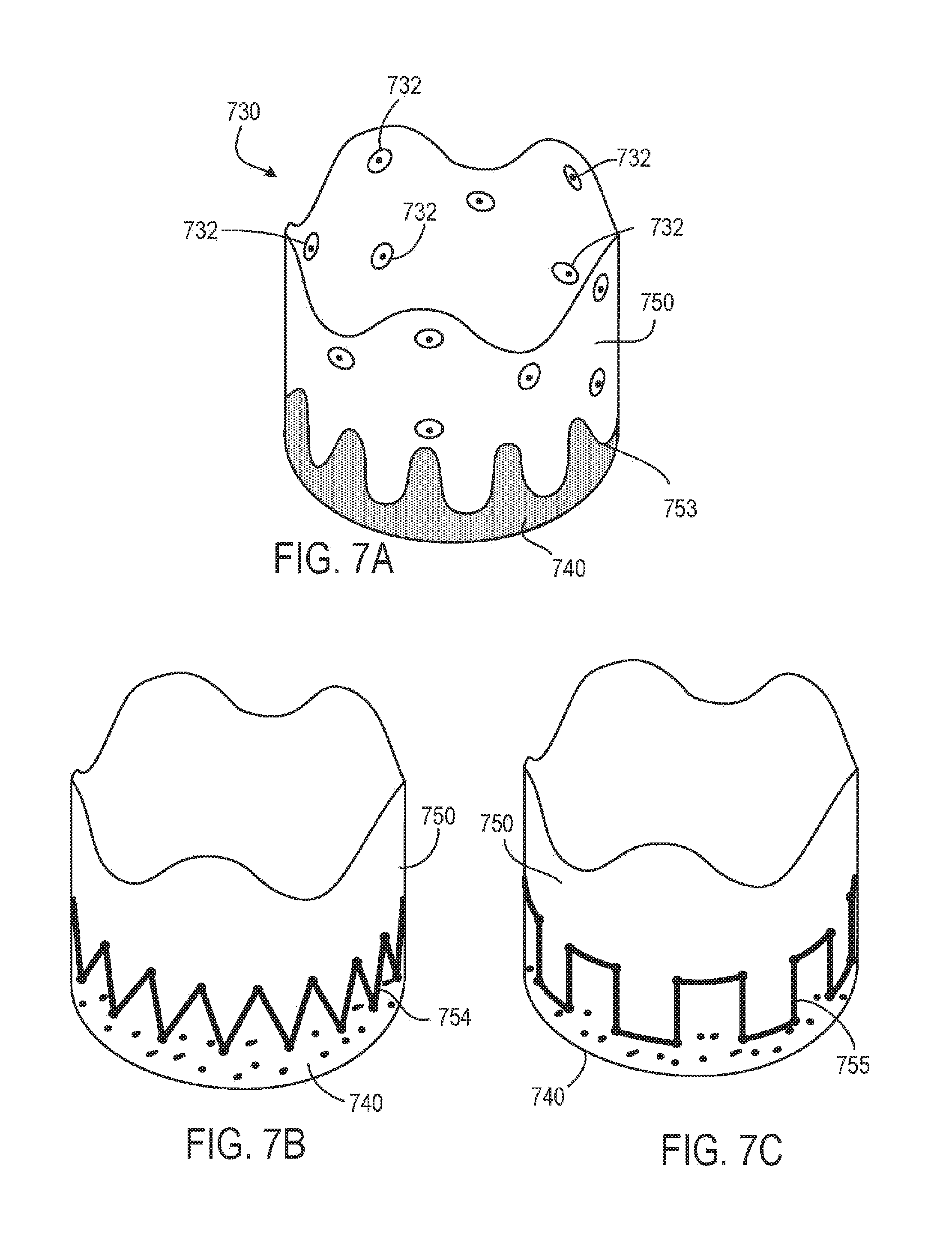
D00018
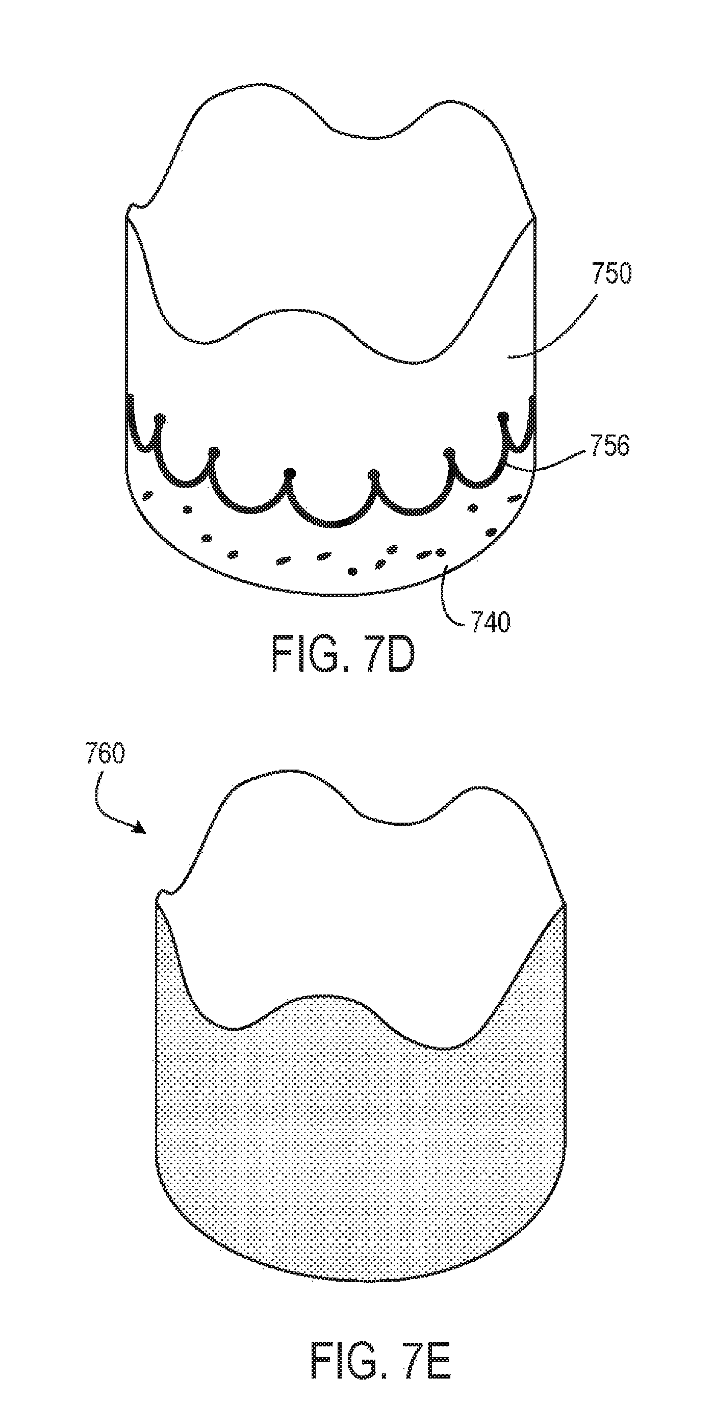
XML
uspto.report is an independent third-party trademark research tool that is not affiliated, endorsed, or sponsored by the United States Patent and Trademark Office (USPTO) or any other governmental organization. The information provided by uspto.report is based on publicly available data at the time of writing and is intended for informational purposes only.
While we strive to provide accurate and up-to-date information, we do not guarantee the accuracy, completeness, reliability, or suitability of the information displayed on this site. The use of this site is at your own risk. Any reliance you place on such information is therefore strictly at your own risk.
All official trademark data, including owner information, should be verified by visiting the official USPTO website at www.uspto.gov. This site is not intended to replace professional legal advice and should not be used as a substitute for consulting with a legal professional who is knowledgeable about trademark law.