Stent loading tool and method for use thereof
Tuval , et al. Ja
U.S. patent number 10,188,516 [Application Number 15/183,208] was granted by the patent office on 2019-01-29 for stent loading tool and method for use thereof. This patent grant is currently assigned to Medtronic Ventor Technologies Ltd.. The grantee listed for this patent is Medtronic Ventor Technologies Ltd.. Invention is credited to Raphael Benary, Guy Ezekiel, Ido Kilemnik, Igor Kovalsky, Yuri Sudin, Yosi Tuval.
View All Diagrams
| United States Patent | 10,188,516 |
| Tuval , et al. | January 29, 2019 |
Stent loading tool and method for use thereof
Abstract
A loading tool for withdrawing, crimping, and loading a stent-mounted valve into a delivery catheter, and for pushing the stent-mounted valve from the delivery catheter into a native heart valve orifice. The loading tool comprises at least one connector adapted for being removably connected to the stent of the stent-mounted valve. A crimping tool having a generally converging shape is adapted for use with the loading tool. Following connection of the loading tool to the stent-mounted valve, the loading tool operates to allow the stent-mounted valve to be drawn through the crimping tool, and loaded, in, a crimped state, into a delivery catheter. Also disclosed is a kit of the of the various components for effecting the delivery of the stent-mounted valve and a method for withdrawing, crimping, and loading a stent-mounted valve from a storage container into a delivery catheter for the performance of a transcatheter valve implantation procedure.
| Inventors: | Tuval; Yosi (Even Yehuda, IL), Sudin; Yuri (Netanya, IL), Kilemnik; Ido (Herzliya, IL), Kovalsky; Igor (Minnetonka, MN), Benary; Raphael (Tel Aviv, IL), Ezekiel; Guy (Netanya, IL) | ||||||||||
|---|---|---|---|---|---|---|---|---|---|---|---|
| Applicant: |
|
||||||||||
| Assignee: | Medtronic Ventor Technologies
Ltd. (Netanya, IL) |
||||||||||
| Family ID: | 40382910 | ||||||||||
| Appl. No.: | 15/183,208 | ||||||||||
| Filed: | June 15, 2016 |
Prior Publication Data
| Document Identifier | Publication Date | |
|---|---|---|
| US 20160361167 A1 | Dec 15, 2016 | |
Related U.S. Patent Documents
| Application Number | Filing Date | Patent Number | Issue Date | ||
|---|---|---|---|---|---|
| 14192614 | Feb 27, 2014 | 9393112 | |||
| 11841004 | Jun 10, 2014 | 8747458 | |||
| Current U.S. Class: | 1/1 |
| Current CPC Class: | A61F 2/0095 (20130101); A61F 2/2427 (20130101); A61F 2/2415 (20130101); A61F 2/2436 (20130101); A61F 2/2418 (20130101); A61F 2/9522 (20200501); A61F 2220/0016 (20130101); A61F 2230/0054 (20130101) |
| Current International Class: | A61F 2/24 (20060101); A61F 2/00 (20060101); A61F 2/95 (20130101) |
References Cited [Referenced By]
U.S. Patent Documents
| 3334629 | August 1967 | Cohn |
| 3409013 | November 1968 | Berry |
| 3540431 | November 1970 | Mobin-Uddin |
| 3587115 | June 1971 | Shiley |
| 3628535 | December 1971 | Ostrowsky et al. |
| 3642004 | February 1972 | Osthagen et al. |
| 3657744 | April 1972 | Ersek |
| 3671979 | June 1972 | Moulopoulos |
| 3714671 | February 1973 | Edwards et al. |
| 3755823 | September 1973 | Hancock |
| 3795246 | March 1974 | Sturgeon |
| 3839741 | October 1974 | Haller |
| 3868956 | March 1975 | Alfidi et al. |
| 3874388 | April 1975 | King et al. |
| 4035849 | July 1977 | Angell et al. |
| 4056854 | November 1977 | Boretos et al. |
| 4106129 | August 1978 | Carpentier et al. |
| 4222126 | September 1980 | Boretos et al. |
| 4233690 | November 1980 | Akins |
| 4265694 | May 1981 | Boretos |
| 4291420 | September 1981 | Reul |
| 4297749 | November 1981 | Davis et al. |
| 4339831 | July 1982 | Johnson |
| 4343048 | August 1982 | Ross et al. |
| 4345340 | August 1982 | Rosen |
| 4425908 | January 1984 | Simon |
| 4470157 | September 1984 | Love |
| 4501030 | February 1985 | Lane |
| 4574803 | March 1986 | Storz |
| 4580568 | April 1986 | Gianturco |
| 4592340 | June 1986 | Boyles |
| 4610688 | September 1986 | Silvestrini et al. |
| 4612011 | September 1986 | Kautzky |
| 4647283 | March 1987 | Carpentier et al. |
| 4648881 | March 1987 | Carpentier et al. |
| 4655771 | April 1987 | Wallsten |
| 4662885 | May 1987 | DiPisa, Jr. |
| 4665906 | May 1987 | Jervis |
| 4681908 | July 1987 | Broderick et al. |
| 4710192 | December 1987 | Liotta et al. |
| 4733665 | March 1988 | Palmaz |
| 4777951 | October 1988 | Cribier et al. |
| 4787899 | November 1988 | Lazarus |
| 4796629 | January 1989 | Grayzel |
| 4797901 | January 1989 | Baykut |
| 4819751 | April 1989 | Shimada et al. |
| 4834755 | May 1989 | Silvestrini et al. |
| 4856516 | August 1989 | Hillstead |
| 4872874 | October 1989 | Taheri |
| 4878495 | November 1989 | Grayzel |
| 4878906 | November 1989 | Lindemann et al. |
| 4883458 | November 1989 | Shiber |
| 4909252 | March 1990 | Goldberger |
| 4917102 | April 1990 | Miller et al. |
| 4922905 | May 1990 | Stecker |
| 4954126 | September 1990 | Wallsten |
| 4966604 | October 1990 | Reiss |
| 4979939 | December 1990 | Shiber |
| 4986830 | January 1991 | Owens et al. |
| 4994077 | February 1991 | Dobben |
| 5002559 | March 1991 | Tower |
| 5007896 | April 1991 | Shiber |
| 5026366 | June 1991 | Leckrone |
| 5032128 | July 1991 | Alonso |
| 5037434 | August 1991 | Lane |
| 5047041 | September 1991 | Samuels |
| 5059177 | October 1991 | Towne et al. |
| 5061273 | October 1991 | Yock |
| 5085635 | February 1992 | Cragg |
| 5089015 | February 1992 | Ross |
| 5152771 | October 1992 | Sabbaghian et al. |
| 5161547 | November 1992 | Tower |
| 5163953 | November 1992 | Vince |
| 5167628 | December 1992 | Boyles |
| 5217483 | July 1993 | Tower |
| 5232445 | August 1993 | Bonzel |
| 5272909 | December 1993 | Nguyen et al. |
| 5295958 | March 1994 | Shturman |
| 5327774 | July 1994 | Nguyen et al. |
| 5332402 | July 1994 | Teitelbaum et al. |
| 5350398 | September 1994 | Pavcnik et al. |
| 5370685 | December 1994 | Stevens |
| 5389106 | February 1995 | Tower |
| 5397351 | March 1995 | Pavcnik et al. |
| 5411552 | May 1995 | Andersen et al. |
| 5415633 | May 1995 | Lazarus et al. |
| 5431676 | July 1995 | Dubrul et al. |
| 5443446 | August 1995 | Shturman |
| 5449384 | September 1995 | Johnson |
| 5480424 | January 1996 | Cox |
| 5489294 | February 1996 | McVenes et al. |
| 5496346 | March 1996 | Horzewski et al. |
| 5500014 | March 1996 | Quijano et al. |
| 5507767 | April 1996 | Maeda et al. |
| 5545209 | August 1996 | Roberts et al. |
| 5545211 | August 1996 | An et al. |
| 5545214 | August 1996 | Stevens |
| 5554185 | September 1996 | Block et al. |
| 5575818 | November 1996 | Pinchuk |
| 5580922 | December 1996 | Park et al. |
| 5591195 | January 1997 | Taheri et al. |
| 5609626 | March 1997 | Quijano et al. |
| 5645559 | July 1997 | Hachtman et al. |
| 5665115 | September 1997 | Cragg |
| 5667523 | September 1997 | Bynon et al. |
| 5674277 | October 1997 | Freitag |
| 5695498 | December 1997 | Tower |
| 5702368 | December 1997 | Stevens et al. |
| 5713953 | February 1998 | Vallana et al. |
| 5716417 | February 1998 | Girard et al. |
| 5746709 | May 1998 | Rom et al. |
| 5749890 | May 1998 | Shaknovich |
| 5766151 | June 1998 | Valley et al. |
| 5782809 | July 1998 | Umeno et al. |
| 5800456 | September 1998 | Maeda et al. |
| 5800508 | September 1998 | Goicoechea et al. |
| 5817126 | October 1998 | Imran |
| 5824041 | October 1998 | Lenker |
| 5824043 | October 1998 | Cottone, Jr. |
| 5824053 | October 1998 | Khosravi et al. |
| 5824056 | October 1998 | Rosenberg |
| 5824061 | October 1998 | Quijano et al. |
| 5824064 | October 1998 | Taheri |
| 5840081 | November 1998 | Andersen et al. |
| 5843158 | December 1998 | Lenker et al. |
| 5851232 | December 1998 | Lois |
| 5855597 | January 1999 | Jayaraman |
| 5855601 | January 1999 | Bessler et al. |
| 5860996 | January 1999 | Tower |
| 5861028 | January 1999 | Angell |
| 5868783 | February 1999 | Tower |
| 5876448 | March 1999 | Thompson et al. |
| 5888201 | March 1999 | Stinson et al. |
| 5891191 | April 1999 | Stinson |
| 5906619 | May 1999 | Olson et al. |
| 5907893 | June 1999 | Zadno-Azizi et al. |
| 5911752 | June 1999 | Dustrude et al. |
| 5913842 | June 1999 | Boyd et al. |
| 5925063 | July 1999 | Khosravi |
| 5944738 | August 1999 | Amplatz et al. |
| 5954766 | September 1999 | Zadno-Azizi et al. |
| 5957949 | September 1999 | Leonhardt et al. |
| 5968068 | October 1999 | Dehdashtian et al. |
| 5984957 | November 1999 | Laptewicz, Jr. et al. |
| 5997573 | December 1999 | Quijano et al. |
| 6022370 | February 2000 | Tower |
| 6027525 | February 2000 | Suh et al. |
| 6029671 | February 2000 | Stevens et al. |
| 6042589 | March 2000 | Marianne |
| 6042598 | March 2000 | Tsugita et al. |
| 6051104 | April 2000 | Jang |
| 6059809 | May 2000 | Amor et al. |
| 6110201 | August 2000 | Quijano et al. |
| 6123723 | September 2000 | Konya et al. |
| 6146366 | November 2000 | Schachar |
| 6159239 | December 2000 | Greenhalgh |
| 6162208 | December 2000 | Hipps |
| 6162245 | December 2000 | Jayaraman |
| 6164339 | December 2000 | Greenhalgh |
| 6168614 | January 2001 | Andersen et al. |
| 6171335 | January 2001 | Wheatley et al. |
| 6192944 | February 2001 | Greenhalgh |
| 6200336 | March 2001 | Pavcnik et al. |
| 6203550 | March 2001 | Olson |
| 6210408 | April 2001 | Chandrasekaran et al. |
| 6218662 | April 2001 | Tchakarov et al. |
| 6221006 | April 2001 | Dubrul et al. |
| 6221091 | April 2001 | Khosravi |
| 6241757 | June 2001 | An et al. |
| 6245102 | June 2001 | Jayaraman |
| 6248116 | June 2001 | Chevilon |
| 6258114 | July 2001 | Konya et al. |
| 6258115 | July 2001 | Dubrul |
| 6258120 | July 2001 | McKenzie et al. |
| 6277555 | August 2001 | Duran et al. |
| 6299637 | October 2001 | Shaolia et al. |
| 6302906 | October 2001 | Goicoechea et al. |
| 6309382 | October 2001 | Garrison et al. |
| 6309417 | October 2001 | Spence et al. |
| 6327772 | December 2001 | Zadno-Azizi et al. |
| 6338735 | January 2002 | Stevens |
| 6348063 | February 2002 | Yassour et al. |
| 6350277 | February 2002 | Kocur |
| 6352708 | March 2002 | Duran et al. |
| 6371970 | April 2002 | Khosravi et al. |
| 6371983 | April 2002 | Lane |
| 6379383 | April 2002 | Palmaz et al. |
| 6380457 | April 2002 | Yurek et al. |
| 6398807 | June 2002 | Chouinard et al. |
| 6409750 | June 2002 | Hyodoh et al. |
| 6425916 | July 2002 | Garrison et al. |
| 6440164 | August 2002 | DiMatteo et al. |
| 6454799 | September 2002 | Schreck |
| 6458153 | October 2002 | Bailey et al. |
| 6461382 | October 2002 | Cao |
| 6468303 | October 2002 | Amplatz et al. |
| 6475239 | November 2002 | Campbell et al. |
| 6482228 | November 2002 | Norred |
| 6488704 | December 2002 | Connelly et al. |
| 6494909 | December 2002 | Greenhalgh |
| 6503272 | January 2003 | Duerig et al. |
| 6508833 | January 2003 | Pavcnik et al. |
| 6527800 | March 2003 | McGuckin, Jr. et al. |
| 6530949 | March 2003 | Konya et al. |
| 6530952 | March 2003 | Vesely |
| 6559603 | May 2003 | Iwami |
| 6562031 | May 2003 | Chandrasekaran et al. |
| 6562058 | May 2003 | Seguin et al. |
| 6569196 | May 2003 | Vesely |
| 6582462 | June 2003 | Andersen et al. |
| 6585758 | July 2003 | Chouinard et al. |
| 6592546 | July 2003 | Barbut et al. |
| 6605112 | August 2003 | Moll et al. |
| 6613077 | September 2003 | Gilligan et al. |
| 6622604 | September 2003 | Chouinard et al. |
| 6627873 | September 2003 | Tchakarov et al. |
| 6632243 | October 2003 | Zadno-Azizi et al. |
| 6635068 | October 2003 | Dubrul et al. |
| 6652571 | November 2003 | White et al. |
| 6652578 | November 2003 | Bailey et al. |
| 6656213 | December 2003 | Solem |
| 6663663 | December 2003 | Kim et al. |
| 6669724 | December 2003 | Park et al. |
| 6673089 | January 2004 | Yassour et al. |
| 6673109 | January 2004 | Cox |
| 6676698 | January 2004 | McGuckin, Jr. et al. |
| 6682558 | January 2004 | Tu et al. |
| 6682559 | January 2004 | Myers et al. |
| 6685739 | February 2004 | DiMatteo et al. |
| 6689144 | February 2004 | Gerberding |
| 6689164 | February 2004 | Seguin |
| 6692512 | February 2004 | Jang |
| 6692513 | February 2004 | Streeter et al. |
| 6695878 | February 2004 | McGuckin, Jr. et al. |
| 6702851 | March 2004 | Chinn et al. |
| 6719789 | April 2004 | Cox |
| 6730118 | May 2004 | Spenser et al. |
| 6730377 | May 2004 | Wang |
| 6733525 | May 2004 | Yang et al. |
| 6736846 | May 2004 | Cox |
| 6752828 | June 2004 | Thornton |
| 6758855 | July 2004 | Fulton, III et al. |
| 6769434 | August 2004 | Liddicoat et al. |
| 6786925 | September 2004 | Schoon |
| 6790229 | September 2004 | Berreklouw |
| 6792979 | September 2004 | Konya et al. |
| 6797002 | September 2004 | Spence |
| 6821297 | November 2004 | Snyders |
| 6830575 | December 2004 | Stenzel et al. |
| 6830584 | December 2004 | Seguin |
| 6830585 | December 2004 | Artof |
| 6846325 | January 2005 | Liddicoat |
| 6866650 | March 2005 | Stevens |
| 6872223 | March 2005 | Roberts |
| 6875231 | April 2005 | Anduiza et al. |
| 6883522 | April 2005 | Spence et al. |
| 6887266 | May 2005 | Williams et al. |
| 6890330 | May 2005 | Streeter et al. |
| 6893460 | May 2005 | Spenser et al. |
| 6896690 | May 2005 | Lambrecht et al. |
| 6908481 | June 2005 | Cribier |
| 6913600 | July 2005 | Valley et al. |
| 6929653 | August 2005 | Streeter |
| 6936066 | August 2005 | Palmaz et al. |
| 6939365 | September 2005 | Fogarty et al. |
| 6951571 | October 2005 | Srivastava |
| 6974474 | December 2005 | Pavcnik et al. |
| 6974476 | December 2005 | McGuckin et al. |
| 6986742 | January 2006 | Hart et al. |
| 6989027 | January 2006 | Allen et al. |
| 6989028 | January 2006 | Lashinski et al. |
| 6991649 | January 2006 | Sleevers |
| 7011681 | March 2006 | Vesely |
| 7018401 | March 2006 | Hyodoh et al. |
| 7041128 | May 2006 | Mcguckin, Jr. et al. |
| 7044966 | May 2006 | Svanjdze et al. |
| 7048014 | May 2006 | Hyodoh et al. |
| 7097659 | August 2006 | Woolfson et al. |
| 7101396 | September 2006 | Artof et al. |
| 7105016 | September 2006 | Shui et al. |
| 7115141 | October 2006 | Menz et al. |
| 7128759 | October 2006 | Osborne et al. |
| 7144408 | December 2006 | Keegan et al. |
| 7147663 | December 2006 | Berg et al. |
| 7153324 | December 2006 | Case et al. |
| 7160319 | January 2007 | Chouinard et al. |
| 7175656 | February 2007 | Khairkhahan |
| 7186265 | March 2007 | Sharkawy et al. |
| 7195641 | March 2007 | Palmaz et al. |
| 7198646 | April 2007 | Figulla et al. |
| 7201761 | April 2007 | Woolfson et al. |
| 7201772 | April 2007 | Schwammenthal et al. |
| 7252682 | August 2007 | Seguin |
| 7300457 | November 2007 | Palmaz |
| 7300463 | November 2007 | Liddicoat |
| 7316706 | January 2008 | Bloom et al. |
| 7329278 | February 2008 | Seguin |
| 7335218 | February 2008 | Wilson et al. |
| 7338520 | March 2008 | Bailey et al. |
| 7374571 | May 2008 | Pease et al. |
| 7377938 | May 2008 | Sarac et al. |
| 7381218 | June 2008 | Shreck |
| 7384411 | June 2008 | Condado |
| 7429269 | September 2008 | Schwammenthal et al. |
| 7442204 | October 2008 | Schwammenthal et al. |
| 7462191 | December 2008 | Spenser et al. |
| 7470284 | December 2008 | Lambrecht et al. |
| 7481838 | January 2009 | Carpentier et al. |
| 7544206 | June 2009 | Cohn et al. |
| 7547322 | June 2009 | Sarac et al. |
| 7556646 | July 2009 | Yang et al. |
| 7806919 | October 2010 | Bloom et al. |
| 8052750 | November 2011 | Tuval |
| 8167932 | May 2012 | Bourang et al. |
| 8348995 | January 2013 | Tuval |
| 8348996 | January 2013 | Tuval |
| 8414643 | April 2013 | Tuval |
| 8876895 | November 2014 | Tuval |
| 2001/0002445 | March 2001 | Vesely |
| 2001/0001314 | May 2001 | Davison et al. |
| 2001/0007956 | July 2001 | Letac et al. |
| 2001/0010017 | July 2001 | Letac et al. |
| 2001/0011189 | August 2001 | Drasler et al. |
| 2001/0021872 | September 2001 | Bailey et al. |
| 2001/0025196 | September 2001 | Chinn et al. |
| 2001/0032013 | October 2001 | Marton |
| 2001/0039450 | November 2001 | Pavcnik et al. |
| 2001/0041928 | November 2001 | Pavcnik et al. |
| 2001/0044591 | November 2001 | Stevens et al. |
| 2001/0044647 | November 2001 | Pinchuk et al. |
| 2002/0010508 | January 2002 | Chobotov |
| 2002/0029014 | March 2002 | Jayaraman |
| 2002/0032480 | March 2002 | Spence et al. |
| 2002/0032481 | March 2002 | Gabbay |
| 2002/0035396 | March 2002 | Heath |
| 2002/0042650 | April 2002 | Vardi et al. |
| 2002/0052651 | May 2002 | Myers et al. |
| 2002/0058995 | May 2002 | Stevens |
| 2002/0072789 | June 2002 | Hackett et al. |
| 2002/0077696 | June 2002 | Zadno-Azizi et al. |
| 2002/0095209 | July 2002 | Zadno-Azizi et al. |
| 2002/0099439 | July 2002 | Schwartz et al. |
| 2002/0103533 | August 2002 | Langberg et al. |
| 2002/0107565 | August 2002 | Greenhalgh |
| 2002/0111674 | August 2002 | Chouinard et al. |
| 2002/0123802 | September 2002 | Snyders |
| 2002/0133183 | September 2002 | Lentz et al. |
| 2002/0138138 | September 2002 | Yang |
| 2002/0151970 | October 2002 | Garrison et al. |
| 2002/0161392 | October 2002 | Dubrul |
| 2002/0161394 | October 2002 | Macoviak et al. |
| 2002/0193871 | December 2002 | Beyersdorf et al. |
| 2003/0014104 | January 2003 | Cribier |
| 2003/0023300 | January 2003 | Bailey et al. |
| 2003/0023303 | January 2003 | Palmaz et al. |
| 2003/0028247 | February 2003 | Cali |
| 2003/0036791 | February 2003 | Philipp et al. |
| 2003/0040771 | February 2003 | Hyodoh et al. |
| 2003/0040772 | February 2003 | Hyodoh et al. |
| 2003/0040792 | February 2003 | Gabbay |
| 2003/0050694 | March 2003 | Yang et al. |
| 2003/0055495 | March 2003 | Pease et al. |
| 2003/0065386 | April 2003 | Weadock |
| 2003/0069492 | April 2003 | Abrams et al. |
| 2003/0109924 | June 2003 | Cribier |
| 2003/0125795 | July 2003 | Pavcnik et al. |
| 2003/0130726 | July 2003 | Thorpe et al. |
| 2003/0130729 | July 2003 | Paniagua et al. |
| 2003/0139804 | July 2003 | Hankh et al. |
| 2003/0149476 | July 2003 | Damm et al. |
| 2003/0149475 | August 2003 | Hyodoh et al. |
| 2003/0149478 | August 2003 | Figulla et al. |
| 2003/0153974 | August 2003 | Spenser et al. |
| 2003/0181850 | September 2003 | Diamond et al. |
| 2003/0191519 | October 2003 | Lombardi et al. |
| 2003/0199913 | October 2003 | Dubrul et al. |
| 2003/0199963 | October 2003 | Tower et al. |
| 2003/0199971 | October 2003 | Tower et al. |
| 2003/0199972 | October 2003 | Zadno-Azizi et al. |
| 2003/0212410 | November 2003 | Stenzel et al. |
| 2003/0212452 | November 2003 | Zadno-Azizi et al. |
| 2003/0212454 | November 2003 | Scott et al. |
| 2003/0225445 | December 2003 | Derus et al. |
| 2004/0019374 | January 2004 | Hojeibane et al. |
| 2004/0034411 | February 2004 | Quijano et al. |
| 2004/0039436 | February 2004 | Spenser et al. |
| 2004/0049224 | March 2004 | Buehlmann et al. |
| 2004/0049262 | March 2004 | Obermiller et al. |
| 2004/0049266 | March 2004 | Anduiza et al. |
| 2004/0082904 | April 2004 | Houde et al. |
| 2004/0088045 | May 2004 | Cox |
| 2004/0092858 | May 2004 | Wilson et al. |
| 2004/0092989 | May 2004 | Wilson et al. |
| 2004/0093005 | May 2004 | Durcan |
| 2004/0093060 | May 2004 | Sequin et al. |
| 2004/0093075 | May 2004 | Kuehn |
| 2004/0097788 | May 2004 | Mourles et al. |
| 2004/0098112 | May 2004 | DiMatteo et al. |
| 2004/0106976 | June 2004 | Bailey et al. |
| 2004/0106990 | June 2004 | Spence et al. |
| 2004/0111096 | June 2004 | Tu et al. |
| 2004/0116951 | June 2004 | Rosengart |
| 2004/0117004 | June 2004 | Osborne et al. |
| 2004/0122468 | June 2004 | Yodfat et al. |
| 2004/0122514 | June 2004 | Fogarty et al. |
| 2004/0122516 | June 2004 | Fogarty |
| 2004/0127979 | July 2004 | Wilson |
| 2004/0138742 | July 2004 | Myers et al. |
| 2004/0138743 | July 2004 | Myers et al. |
| 2004/0153146 | August 2004 | Laskinski et al. |
| 2004/0167573 | August 2004 | Williamson |
| 2004/0167620 | August 2004 | Ortiz |
| 2004/0186563 | September 2004 | Lobbi |
| 2004/0193261 | September 2004 | Berreklouw |
| 2004/0210240 | October 2004 | Saint |
| 2004/0210304 | October 2004 | Seguin et al. |
| 2004/0210307 | October 2004 | Khairkhahan |
| 2004/0215333 | October 2004 | Duran |
| 2004/0215339 | October 2004 | Drasler et al. |
| 2004/0225353 | November 2004 | McGuckin, Jr. |
| 2004/0225354 | November 2004 | Allen |
| 2004/0225355 | November 2004 | Stevens |
| 2004/0254636 | December 2004 | Flagle et al. |
| 2004/0260317 | December 2004 | Bloom et al. |
| 2004/0260389 | December 2004 | Case et al. |
| 2004/0260394 | December 2004 | Douk et al. |
| 2004/0267357 | December 2004 | Allen et al. |
| 2005/0010246 | January 2005 | Streeter |
| 2005/0010285 | January 2005 | Lambrecht et al. |
| 2005/0010287 | January 2005 | Macoviak |
| 2005/0015112 | January 2005 | Cohn et al. |
| 2005/0027348 | February 2005 | Case et al. |
| 2005/0033398 | February 2005 | Seguin |
| 2005/0043790 | February 2005 | Seguin |
| 2005/0049692 | March 2005 | Numamoto |
| 2005/0049696 | March 2005 | Siess |
| 2005/0055088 | March 2005 | Liddicoat et al. |
| 2005/0060029 | March 2005 | Le |
| 2005/0060030 | March 2005 | Lashinski et al. |
| 2005/0075584 | April 2005 | Cali |
| 2005/0075712 | April 2005 | Biancucci |
| 2005/0075717 | April 2005 | Nguyen |
| 2005/0075719 | April 2005 | Bergheim |
| 2005/0075724 | April 2005 | Svanidze |
| 2005/0075727 | April 2005 | Wheatley |
| 2005/0075730 | April 2005 | Myers |
| 2005/0075731 | April 2005 | Artof |
| 2005/0085841 | April 2005 | Eversull et al. |
| 2005/0085842 | April 2005 | Eversull et al. |
| 2005/0085843 | April 2005 | Opolski et al. |
| 2005/0085890 | April 2005 | Rasmussen et al. |
| 2005/0085900 | April 2005 | Case et al. |
| 2005/0096568 | May 2005 | Kato |
| 2005/0096692 | May 2005 | Linder et al. |
| 2005/0096724 | May 2005 | Stenzel et al. |
| 2005/0096734 | May 2005 | Majercak et al. |
| 2005/0096735 | May 2005 | Hojeibane et al. |
| 2005/0096736 | May 2005 | Osse et al. |
| 2005/0096738 | May 2005 | Cali et al. |
| 2005/0107871 | May 2005 | Realyvasquez et al. |
| 2005/0113910 | May 2005 | Paniagua |
| 2005/0119688 | June 2005 | Bergheim |
| 2005/0131438 | June 2005 | Cohn |
| 2005/0137686 | June 2005 | Salahieh |
| 2005/0137688 | June 2005 | Salahieh et al. |
| 2005/0137692 | June 2005 | Haug |
| 2005/0137695 | June 2005 | Salahieh |
| 2005/0137701 | June 2005 | Salahieh |
| 2005/0143807 | June 2005 | Pavcnik et al. |
| 2005/0143809 | June 2005 | Salahieh |
| 2005/0148997 | July 2005 | Valley et al. |
| 2005/0149181 | July 2005 | Eberhardt |
| 2005/0165477 | July 2005 | Anduiza et al. |
| 2005/0187616 | August 2005 | Realyvasquez |
| 2005/0197695 | September 2005 | Stacchino et al. |
| 2005/0203549 | September 2005 | Realyvasquez |
| 2005/0203605 | September 2005 | Dolan |
| 2005/0203618 | September 2005 | Sharkawy |
| 2005/0222674 | October 2005 | Paine |
| 2005/0228495 | October 2005 | Macoviak |
| 2005/0234546 | October 2005 | Nugent |
| 2005/0240200 | October 2005 | Bergheim |
| 2005/0240263 | October 2005 | Fogarty et al. |
| 2005/0261759 | November 2005 | Lambrecht et al. |
| 2005/0283962 | December 2005 | Boudjemline |
| 2006/0004439 | January 2006 | Spenser et al. |
| 2006/0004469 | January 2006 | Sokel |
| 2006/0009841 | January 2006 | McGuckin et al. |
| 2006/0052867 | March 2006 | Revuelta et al. |
| 2006/0058775 | March 2006 | Stevens et al. |
| 2006/0089711 | April 2006 | Dolan |
| 2006/0100685 | May 2006 | Seguin et al. |
| 2006/0116757 | June 2006 | Lashinski et al. |
| 2006/0135964 | June 2006 | Vesely |
| 2006/0142848 | June 2006 | Gabbay |
| 2006/0162731 | July 2006 | Wondka |
| 2006/0167474 | July 2006 | Bloom et al. |
| 2006/0178740 | August 2006 | Stacchino et al. |
| 2006/0195134 | August 2006 | Crittenden |
| 2006/0206192 | September 2006 | Tower et al. |
| 2006/0206202 | September 2006 | Bonhoefer et al. |
| 2006/0212111 | September 2006 | Case et al. |
| 2006/0247763 | November 2006 | Slater |
| 2006/0259134 | November 2006 | Schwammenthal et al. |
| 2006/0259136 | November 2006 | Nguyen et al. |
| 2006/0259137 | November 2006 | Artof et al. |
| 2006/0265056 | November 2006 | Nguyen et al. |
| 2006/0271081 | November 2006 | Realyvasquez |
| 2006/0271166 | November 2006 | Thill et al. |
| 2006/0271175 | November 2006 | Woolfson et al. |
| 2006/0276874 | December 2006 | Wilson et al. |
| 2006/0276882 | December 2006 | Case et al. |
| 2006/0282161 | December 2006 | Huynh et al. |
| 2007/0005129 | January 2007 | Damm et al. |
| 2007/0005131 | January 2007 | Taylor |
| 2007/0010878 | January 2007 | Raffiee et al. |
| 2007/0016286 | January 2007 | Case et al. |
| 2007/0027518 | February 2007 | Herrmann et al. |
| 2007/0027533 | February 2007 | Douk |
| 2007/0038295 | February 2007 | Case et al. |
| 2007/0043431 | February 2007 | Melsheimer |
| 2007/0043435 | February 2007 | Seguin et al. |
| 2007/0051377 | March 2007 | Douk et al. |
| 2007/0073392 | March 2007 | Heyninck-Janitz |
| 2007/0078509 | April 2007 | Lotfy et al. |
| 2007/0078510 | April 2007 | Ryan |
| 2007/0088431 | April 2007 | Bourang et al. |
| 2007/0093869 | April 2007 | Bloom et al. |
| 2007/0100439 | May 2007 | Cangialosi |
| 2007/0100440 | May 2007 | Figulla |
| 2007/0100449 | May 2007 | O'Neil et al. |
| 2007/0112415 | May 2007 | Barlett |
| 2007/0162102 | July 2007 | Ryan et al. |
| 2007/0162113 | July 2007 | Sharkawy et al. |
| 2007/0185513 | August 2007 | Woolfson et al. |
| 2007/0203391 | August 2007 | Bloom et al. |
| 2007/0225681 | September 2007 | House |
| 2007/0232898 | October 2007 | Huynh et al. |
| 2007/0233228 | October 2007 | Eberhardt et al. |
| 2007/0233237 | October 2007 | Krivoruchko |
| 2007/0233238 | October 2007 | Huynh et al. |
| 2007/0238979 | October 2007 | Huynh et al. |
| 2007/0239254 | October 2007 | Marchand et al. |
| 2007/0239265 | October 2007 | Birdsall |
| 2007/0239266 | October 2007 | Birdsall |
| 2007/0239269 | October 2007 | Dolan et al. |
| 2007/0239271 | October 2007 | Nguyen |
| 2007/0239273 | October 2007 | Allen |
| 2007/0244544 | October 2007 | Birdsall et al. |
| 2007/0244545 | October 2007 | Birdsall et al. |
| 2007/0244546 | October 2007 | Francis |
| 2007/0244553 | October 2007 | Rafiee et al. |
| 2007/0244554 | October 2007 | Rafiee et al. |
| 2007/0244555 | October 2007 | Rafiee et al. |
| 2007/0244556 | October 2007 | Rafiee et al. |
| 2007/0244557 | October 2007 | Rafiee et al. |
| 2007/0250160 | October 2007 | Rafiee |
| 2007/0255394 | November 2007 | Ryan |
| 2007/0255396 | November 2007 | Douk et al. |
| 2007/0288000 | December 2007 | Bonan |
| 2008/0004696 | January 2008 | Vesely |
| 2008/0009940 | January 2008 | Cribier |
| 2008/0015671 | January 2008 | Bonhoeffer |
| 2008/0021552 | January 2008 | Gabbay |
| 2008/0048656 | February 2008 | Tan |
| 2008/0065001 | March 2008 | Marchand et al. |
| 2008/0065206 | March 2008 | Liddicoat |
| 2008/0071361 | March 2008 | Tuval et al. |
| 2008/0071362 | March 2008 | Tuval et al. |
| 2008/0071363 | March 2008 | Tuval et al. |
| 2008/0071366 | March 2008 | Tuval et al. |
| 2008/0071368 | March 2008 | Tuval et al. |
| 2008/0077234 | March 2008 | Styrc |
| 2008/0082165 | April 2008 | Wilson et al. |
| 2008/0082166 | April 2008 | Styrc et al. |
| 2008/0133003 | June 2008 | Seguin et al. |
| 2008/0140189 | June 2008 | Nguyen et al. |
| 2008/0147105 | June 2008 | Wilson et al. |
| 2008/0147180 | June 2008 | Ghione et al. |
| 2008/0147181 | June 2008 | Ghione et al. |
| 2008/0147182 | June 2008 | Righini et al. |
| 2008/0154355 | June 2008 | Benichow et al. |
| 2008/0154356 | June 2008 | Obermiller et al. |
| 2008/0161910 | July 2008 | Revuelta et al. |
| 2008/0161911 | July 2008 | Revuelta et al. |
| 2008/0183273 | July 2008 | Mesana et al. |
| 2008/0188928 | August 2008 | Salahieh et al. |
| 2008/0215143 | September 2008 | Seguin et al. |
| 2008/0215144 | September 2008 | Ryan et al. |
| 2008/0228254 | September 2008 | Ryan |
| 2008/0228263 | September 2008 | Ryan |
| 2008/0234797 | September 2008 | Stryc |
| 2008/0243246 | October 2008 | Ryan et al. |
| 2008/0255651 | October 2008 | Dwork |
| 2008/0255660 | October 2008 | Guyenot et al. |
| 2008/0255661 | October 2008 | Straubinger et al. |
| 2008/0262593 | October 2008 | Ryan et al. |
| 2008/0269878 | October 2008 | Iobbi |
| 2009/0005863 | January 2009 | Goetz et al. |
| 2009/0012600 | January 2009 | Styrc et al. |
| 2009/0048656 | February 2009 | Wen |
| 2009/0054976 | February 2009 | Tuval et al. |
| 2009/0069886 | March 2009 | Suri et al. |
| 2009/0069887 | March 2009 | Righini et al. |
| 2009/0069889 | March 2009 | Suri et al. |
| 2009/0082858 | March 2009 | Nugent et al. |
| 2009/0085900 | April 2009 | Weiner |
| 2009/0099653 | April 2009 | Suri et al. |
| 2009/0138079 | May 2009 | Tuval et al. |
| 2009/0164004 | June 2009 | Cohn |
| 2009/0171447 | July 2009 | VonSegesser et al. |
| 2009/0192585 | July 2009 | Bloom et al. |
| 2009/0192586 | July 2009 | Tabor et al. |
| 2009/0192591 | July 2009 | Ryan et al. |
| 2009/0198316 | August 2009 | Laske et al. |
| 2009/0216310 | August 2009 | Straubinger et al. |
| 2009/0216312 | August 2009 | Straubinger et al. |
| 2009/0216313 | August 2009 | Straubinger et al. |
| 2009/0222082 | September 2009 | Lock et al. |
| 2009/0234443 | September 2009 | Ottma et al. |
| 2009/0240264 | September 2009 | Tuval et al. |
| 2009/0240320 | September 2009 | Tuval |
| 2009/0287296 | November 2009 | Manasse |
| 2010/0036479 | February 2010 | Hill et al. |
| 2010/0094411 | April 2010 | Tuval et al. |
| 2010/0100167 | April 2010 | Bortlein et al. |
| 2010/0131054 | May 2010 | Tuval et al. |
| 2010/0137979 | June 2010 | Tuval et al. |
| 2010/0161045 | June 2010 | Righini |
| 2010/0198346 | August 2010 | Keogh et al. |
| 2010/0234940 | September 2010 | Dolan |
| 2010/0256723 | October 2010 | Murray |
| 2007-100074433 | Aug 2007 | CN | |||
| 3640745 | Jun 1987 | DE | |||
| 195 32 846 | Mar 1997 | DE | |||
| 195 46 692 | Jun 1997 | DE | |||
| 195 46 692 | Jun 1997 | DE | |||
| 198 57 887 | Jul 2000 | DE | |||
| 199 07 646 | Aug 2000 | DE | |||
| 100 49 812 | Apr 2002 | DE | |||
| 100 49 813 | Apr 2002 | DE | |||
| 100 49 815 | Apr 2002 | DE | |||
| 1057460 | Jun 2000 | EP | |||
| 1255510 | Nov 2002 | EP | |||
| 1469797 | Nov 2005 | EP | |||
| 2788217 | Dec 1999 | FR | |||
| 2815844 | May 2000 | FR | |||
| 2056023 | Mar 1981 | GB | |||
| 2433700 | Dec 2007 | GB | |||
| 1271508 | Nov 1986 | SU | |||
| 95/29640 | Nov 1995 | WO | |||
| 00/47136 | Aug 2000 | WO | |||
| 01/35870 | May 2001 | WO | |||
| 01/49213 | Jul 2001 | WO | |||
| 01/54625 | Aug 2001 | WO | |||
| 01/62189 | Aug 2001 | WO | |||
| 01/64137 | Sep 2001 | WO | |||
| 02/22054 | Mar 2002 | WO | |||
| 02/36048 | May 2002 | WO | |||
| 03/003943 | Jan 2003 | WO | |||
| 03/003949 | Jan 2003 | WO | |||
| 03/011195 | Feb 2003 | WO | |||
Attorney, Agent or Firm: Medler Ferro Woodhouse & Mills PLLC
Parent Case Text
RELATED APPLICATIONS
This application is a Continuation of and claims the benefit of U.S. patent application Ser. No. 14/192,614 filed Feb. 27, 2014, now allowed, which is a Division of and claims the benefit of U.S. patent application Ser. No. 11/841,004 filed Aug. 20, 2007, now U.S. Pat. No. 8,747,458. The disclosures of which are herein incorporated by reference in their entirety.
Claims
We claim:
1. A loading system for loading a valve prosthesis into a delivery catheter, the loading system comprising: a loading tool comprising a loading tool connection member, wherein the loading tool connection member comprises a first plurality of prongs, wherein the loading tool connection member includes an open state with the first plurality of prongs flared outwardly and a closed state with the first plurality of prongs radially contracted; a valve prosthesis including a radially compressed configuration and a radially expanded configuration, the valve prosthesis comprising valve prosthesis connection members configured to removably engage with a respective one of the first plurality of prongs, wherein the loading tool is configured to engage the valve prosthesis with the valve prosthesis in the radially expanded configuration and the loading tool in the open state; and a crimping tool comprising a proximal end and a distal end, wherein the diameter of the distal end is greater than the diameter of the proximal end, wherein the loading tool connection member, in the open state while engaged with the valve prosthesis in the radially expanded configuration, is configured to pass through the crimping tool such that the valve prosthesis crimps from the radially expanded configuration to the radially compressed configuration and the loading tool connection member radially contracts from the open state to the closed state.
2. The loading system of claim 1, wherein the loading tool is configured to automatically disengage from the valve prosthesis when the valve prosthesis is unloaded from a delivery catheter.
3. The loading system of claim 1, wherein the loading tool further comprises a pusher connector disposed opposite the loading tool connection member, wherein the pusher connector is configured for attachment to an inner shaft of the delivery catheter.
4. The loading system of claim 3, wherein the loading tool further comprises a detachable handle configured for attachment to the pusher connector during crimping of the valve prosthesis, wherein the detachable handle is configured for detachment from pusher connector after crimping of the valve prosthesis such that the pusher connector can be attached to the inner shaft of the delivery catheter.
5. The loading system of claim 1, further comprising a storage container for the valve prosthesis, wherein the loading tool and the crimping tool are provided separately from the storage container for valve prosthesis.
6. The loading system of claim 1, wherein each of the first plurality of prongs includes a radially outwardly facing notch, and wherein the valve prosthesis connection members are configured to be inserted into a respective radially outwardly facing notch.
7. The loading system of claim 1, wherein each of the first plurality of prongs includes a radially outwardly facing hook member, and wherein the valve prosthesis connection members each includes an aperture such that each outwardly facing hook member of the first plurality of prongs is configured to be inserted into the aperture of a corresponding one of the valve prosthesis connection members.
8. The loading system of claim 1, wherein the loading tool comprises a second plurality of prongs that are shorter than the first plurality of prongs, each prong of the second plurality of prongs being disposed circumferentially between a pair of prongs of the first plurality of prongs.
9. The loading system of claim 8, wherein the proximal end of the crimping tool includes an inner surface including an indentation, and wherein the indentation is configured to interact with at least one of the second plurality of prongs to prevent the loading tool from advancing distally through the crimping tool after the at least one of the second plurality of prongs is advanced proximally through the crimping tool such that the at least one of the second plurality of prongs is proximal of the indentation.
10. The loading system of claim 1, wherein the proximal end of the crimping tool includes an inner surface including an indentation, and wherein the indentation is configured to interact with at least one of the first plurality of prongs to prevent the loading tool from advancing distally through the crimping tool after the at least one of the first plurality of prongs is advanced proximally through the crimping tool such that the at least one of the first plurality of prongs is proximal of the indentation.
11. A kit comprising: a loading tool comprising a loading tool connection member, wherein the loading tool connection member comprises a first plurality of prongs, wherein the loading tool connection member includes an open state with the first plurality of prongs flared outwardly and a closed state with the first plurality of prongs radially contracted; a valve prosthesis including a radially compressed configuration and a radially expanded configuration, the valve prosthesis comprising valve prosthesis connection members configured to removably engage with a respective one of the first plurality of prongs, wherein the loading tool is configured to engage the valve prosthesis with the valve prosthesis in the radially expanded configuration and the loading tool in the open state; a crimping tool comprising a proximal end and a distal end, wherein the diameter of the distal end is greater than the diameter of the proximal end; and an openable container surrounding the valve prosthesis, the loading tool, and the crimping tool; wherein the loading tool connection member, in the open state while engaged with the valve prosthesis in the radially expanded configuration, is configured to pass through the crimping tool such that the valve prosthesis crimps from the radially expanded configuration to the radially compressed configuration and the loading tool connection member radially contracts from the open state to the closed state.
12. The kit of claim 11, wherein the loading tool is configured to automatically disengage from the valve prosthesis when the valve prosthesis is unloaded from a delivery catheter.
13. The kit of claim 11, wherein the loading tool further comprises a pusher connector disposed opposite the loading tool connection member, wherein the pusher connector is configured for attachment to an inner shaft of a delivery catheter.
14. The kit of claim 13, wherein the loading tool further comprises a detachable handle configured for attachment to the pusher connector during crimping of the valve prosthesis, wherein the detachable handle is configured for detachment from pusher connector after crimping of the valve prosthesis such that the pusher connector can be attached to the inner shaft of the delivery catheter.
15. The kit of claim 11, wherein each of the first plurality of prongs includes a radially outwardly facing notch, and wherein the valve prosthesis connection members are configured to be inserted into a respective radially outwardly facing notch.
16. The kit of claim 11, wherein each of the first plurality of prongs includes a radially outwardly facing hook member, and wherein the valve prosthesis connection members each includes an aperture such that each outwardly facing hook member of the first plurality of prongs is configured to be inserted the aperture of a corresponding one of the valve prosthesis connection members.
17. The kit of claim 11, wherein the loading tool comprises a second plurality of prongs that are shorter than the first plurality of prongs, each prong of the second plurality of prongs being disposed circumferentially between a pair of prongs of the first plurality of prongs.
18. The loading system of claim 17, wherein the proximal end of the crimping tool includes an inner surface including an indentation, and wherein the indentation is configured to interact with at least one of the second plurality of prongs to prevent the loading tool from advancing distally through the crimping tool after the at least one of the second plurality of prongs is advanced proximally through the crimping tool such that the at least one of the second plurality of prongs is proximal of the indentation.
Description
FIELD OF THE INVENTION
The present invention of a device and methods generally relates to the field of cardiac medical technology. In particular, the device relates to a loading tool that may be used in crimping, loading, and delivery a stent-mounted valve or other expandable prosthetic device.
BACKGROUND OF THE INVENTION
Stents are bioprosthetic devices that are typically used for counteracting restenosis, or the repeated narrowing of a blood vessel. Stents may also be used, for example, as shown in U.S. Patent Application 2006/0149360 to Schwammenthal, et al, as a component of a stent-mounted heart valve with mounted leaflets. The stent mounted valve implant described there includes clamping fingers that secure its position at a native valve orifice of the heart.
Such an implant is delivered to its site in the heart using a catheter assembly. To pass through the catheter, the prosthetic valve must be collapsed to a smaller profile. However, since the stent-mounted prosthetic valve has leaflets of pericardium material, it cannot be delivered to the hospital or medical facility in a collapsed or compressed state. Rather, the step of collapsing the implant for passage through the delivery device must be carried out shortly before the implantation procedure. Consequently, the valve, in an open slate, is delivered to the user in a container and that container typically contains a sterile, preservative medium such as glutaraldehyde.
Thus, prior to the implantation procedure, the stent-mounted valve must first be manually removed from the storage medium package, collapsed (perhaps by crimping), and then loaded into the delivery catheter in that crimped state.
Several cautions are to be observed prior to and during the step of loading the stent-mounted prosthetic valve. Since the material making up the stent is easily deformed or damaged, the stent must be handled with great care. Secondly, the stent must be crimped or otherwise collapsed to the smaller profile so that it fits properly inside of the catheter delivery tube. The step of collapsing the stent is a delicate process and, if not performed properly, may cause delay the implantation procedure or may entail excessive handling of the stent or even damage to the valve. Removal of the stem from the glutaraldehyde liquid medium in the storage and delivery container by surgically-gloved surgical personnel may be awkward.
Specialized tools may be used to minimize the risks associated with preparing the stent-mounted valve for the step of implanting the prosthetic valve in the heart.
U.S. Patent Application No. 2004/0186563, to Lobbi, discloses a heart valve that is loaded into the delivery catheter using a specialized tool. The valve is crimped or collapsed to a smaller profile by pulling it through a conical-shaped region of the specialized tool. One or more filaments threaded through the valve to allow such pulling and consequent crimping of the valve. A drawback to this procedure is that the step of threading the filaments through the valve can be a tedious and time-consuming process. Also, since the filaments have no purpose after the crimping step, they must be removed from the implant prior to the delivery procedure. Removal of the filaments may cause damage to the valve and may even partially undo the crimping step.
U.S. Patent Application No. 2003/0225445 to Derus et al., describes a loading device having a conical-shaped region for facilitating the collapse of a stent. As with the Lobbi procedure, a filament or the like is used to pull the stent through the loading device to collapse it.
Other devices for transferring a stent from a storage container to a delivery tool are described in U.S. Pat. No. 6,090,035 to Campbell, U.S. Pat. No. 5,693,066 to Rupp et al., U.S. Pat. No. 6,123,720 to Anderson et al., and European Patents WO 98/22044 and WO 97/09946, both to Borghi.
None of these patents or patent applications show the device and procedures described further hereinbelow, nor do they satisfactorily solve the problems which have been described above relating to transfer of the valve from a storage device, in which the valve is in an expanded state, to the delivery tool, in which the valve is in a substantially compressed state.
There is thus a need for a tool that allows for transfer of the valve or other prosthetic device from the storage container to the catheter delivery tube, in a relatively simple manner that requires only minimal handling.
SUMMARY OF THE INVENTION
Accordingly, it is a broad object of the present invention to overcome the above-mentioned disadvantages and limitations of the prior art and provide a loading tool suitable for extracting a stent-mounted valve from its packaging, crimping that stent-mounted valve into a profile suitable for introduction into a catheter delivery tube, and loading that stent mounted valve into a catheter delivery tube in a simple and reliable manner.
The described loading and delivery tool may be configured to become a part of the delivery system once it is loaded into a catheter delivery tube. Specifically, the loading tool may join to and be considered to become a part of an inner shaft of the catheter delivery tube, and, together with the inner shaft of the catheter, cooperate to push the stent-mounted valve outward from the catheter delivery tube once the appropriate location in the heart is reached. This functionality is due to the structure (and consequent rigidity) of the loading tool. The filaments used in the crimping step of the procedures found in the Lobbi and Derus et al published applications must be removed prior to the transcatheter procedure. As noted above, the filaments serve no function during the actual implantation of the stent.
The described loading tool may be used for withdrawing, crimping, and loading a stent-mounted valve into a catheter delivery tube, and further for facilitating pushing of the stent-mounted valve from the catheter delivery tube into a native heart valve orifice.
The loading tool may be configured to connect to and to be controllably be disconnected from the stent component of the stent-mounted valve. In one such variation, the loading tool may comprise one or more connectors adapted for being removably connected to the stent of the stent-mounted valve.
The connector or connection section of the loading tool may, for instance, comprise one or more prongs. For instance, the loading tool may comprise three prongs. Where the connector comprises one or more prongs, each prong may be characterized as having a substantially rigid portion and having a less rigid hinge region. Alternatively, each prong arm may be configured so that it flexes along its length. In either case, the flexibility of the prong allows the loading tool to become part of the delivery system during the transcatheter valve placement procedure. The distal end of each prong is configured in such a way that it may be attached to the stem-mounted valve via the stent component. In turn, the stent may include sites, portions, or members to be positioned in such a way to cooperate with, and thereby be attached to, the connector or connecting section of the loading tool. In certain instances, where the design of the stent and the connector permits, the stent may have at least three connecting members positioned around its periphery for facilitating attachment to three cooperating prongs of the loading tool.
Where prongs are used as connectors to the stent, the prongs may have a variety of configurations meeting the goal of removable and controllable attachment to and separation from the stent. In one variation, each prong is formed with a radial outwardly facing notch at its distal end which cooperatively engages a conforming connector of the stent-mounted valve. In usage, the operator places the ends of the prongs over the end of the stent and compresses the prongs on the loading tool to move the notched tips of the prongs and to align each of them with a corresponding connector on the stent. The user then releases the prongs such that each individual prong becomes engaged, with a single stem connecting member.
The prongs may have notches or openings that face outwardly or that face towards the end of the tool. In each instance, suitable interfering members would be employed to allow controllable attachment of the stem to the loading tool and subsequent release of the stent from the loading tool.
The loading tool may be pre-mounted onto the stent-mounted valve and provided in packaging together with a crimping tool. The crimping tool may have a generally converging-shape allowing the user to compress the stent-mounted valve just prior to introduction into the delivery catheter by pulling it from the packaging. This combination may be provided as a kit, perhaps sterilized and perhaps including a preservative for the valve and perhaps including printed instructions for use. In other variations, the loading tool and crimping tool may be provided separately, i.e., not attached to the stent-mounted valve. However, in the latter variation, the components may also be provided as a kit perhaps with separate or integrated packaging.
The crimping tool may have a converging-shape with an open, wide end and a narrower opposing end. The step of pulling the stent-mounted valve through the converging-shape crimping tool with the loading tool causes the stent-mounted valve to become compressed, due to the decreasing diameter of the crimping tool.
Once compressed, the stent-mounted valve (perhaps after a washing step to remove preservative) may be loaded directly into the catheter delivery tube for delivery using the transcatheter procedure. The loading tool and sleet may be configured so that the loading tool also grasps the stent by switching from a larger diameter (or expanded state) to a compressed state a it is drawn through the crimping tool along with the stent-mounted valve.
The loading tool may then be attached to a control and delivery member, e.g., a inner shaft or a catheter delivery tube, and then both the loading tool and the stent-mounted valve are drawn into the catheter delivery tube. This loading tool design greatly increases the ease of transfer of the valve front the storage device to the catheter delivery tube. Also, with this loading tool, the valve is subjected to minimal handling during transfer into the catheter delivery tube, a feature which assures the integrity of the valve itself.
As noted above, in one variation of the described component prongs, each prong is provided with a notched end to engage a cooperative connecting member or site located on, e.g., around the lower periphery of, the stent. In this variation, the diameter of the open connector, is larger than the diameter of the open stent. As the prongs are slightly compressed during attachment to the stent, the opening or notch in the end of the prong envelops a complementary connection on the stent to create and retain the connection with the stent.
In another variation, at least a portion of each of the prongs is constructed of a wire form. Each of the distal ends of the prongs is configured to engage a corresponding opening, e.g., an eye-hole, in a cooperating connector located on the stent.
The loading tool may comprise one or more medically safe polymeric, metallic, or combination materials which preserve a high degree of integrity during the procedure. Suitable materials include metals or alloys such as many of the stainless steels, super-elastic alloys such as NITINOL, titanium and titanium alloys, cobalt chromium alloys, and the like. Suitable materials also include polymers such as many of the Nylons, polycarbonates, polyimides, polyketones (such as polyetheretherketone (PEEK), polyetherketoneketone (PEKK), polyetherketone (PEK), polyetherketoneetherketoneketone (PEKEKK), and polyetheretherketoneketone (PEEKK), and generally a polyaryletheretherketone), and the like. Suitable polymeric materials, whether thermosets or thermoplastic, may be filled with, e.g., glass fibers, carbon fibers, polymeric fibers, ceramic fibers, and the like. The materials should be selected to have an elasticity allowing the loading tool to operate as described here.
The method of loading the stent mounted valve on the loading tool includes, in one variation, slightly compressing the prongs of the loading tool, inserting the prongs within the bottom of the stent-mounted valve, aligning the prongs with the stent connecting members, releasing the prongs to allow outward movement towards the stent causing the stent to become fixed into place. In this manner, the stent-mounted valve becomes connected to the loading tool and may now be drawn through the converging-shape crimping tool.
Once the stent is crimped, the loading tool is then coupled to a component of the delivery catheter assembly. The stool mounted valve and the loading tool are then drawn into the interior of the catheter delivery tube, the converging-shape crimping tool is detached, and the stent-mounted valve and loading tool are retracted farther into the catheter delivery tube in final preparation for the transcatheter procedure.
When the stent-mounted valve is delivered during the transcatheter procedure to the native heart valve, pushing the delivery tool slightly forward within the catheter delivery tube, or holding the stent-mounted valve in place as the catheter delivery tube is moved backward, will cause the stent-mounted valve to be exposed as it is released from constriction of the catheter delivery tube. The stent-mounted valve will then self-expand into position in the native heart valve.
There is also described a system for loading a stent-mounted valve into a catheter delivery tube for performance of a transcatheter valve implantation procedure. The system may include a loading tool configured to be removably connected to the stent of a stent-mounted valve. The loading tool may be configured to be coupled to the inner shaft of a catheter delivery tube. The system may also comprise d crimping tool having a generally converging shape.
The loading tool may comprise a handle detachable from the loading tool after the crimping of the stent-mounted valve is accomplished but prior to attachment of the loading tool to the catheter. By removing the handle, the loading tool and the stent-mounted valve may then be retracted together into the catheter delivery tube.
The stent may be comprised of a wire assembly and formed with a plurality of connecting members for facilitating connection to the prongs of the loading tool. The connecting members may comprise a region of the stern (e.g., when the stent is a wire-based structure or a specific wire is added to a stent structure for the purpose of connecting to the loading tool) or may comprise members specifically provided to cooperatively attach to a prong. In one variation, the prongs each comprise a notch for facilitating connection to the connecting members or regions of the stent. In other variations, the prongs each comprise a hook-shaped member for facilitating connection to the stent
There is also described a method for withdrawing a stent-mounted valve from a storage container, crimping the stent-mounted valve, and loading the crimped stent-mounted valve into a catheter delivery tube for the performance of a transcatheter valve implantation procedure. The method includes:
(a) providing a stent-mounted valve in a substantially open state inside of a storage container;
(b) providing a loading tool comprising at least one connector adapted for being removably connected to the stent-mounted valve, and further adapted for being coupled to a inner shaft of a catheter delivery tube;
(c) providing a generally converging-shape crimping tool;
(d) attaching the loading tool to the stent-mounted valve using the at least one connector;
(e) withdrawing the stent-mounted valve from the storage container using the loading tool;
(f) pulling the stent-mounted valve through the crimping tool using the loading tool such that the stent-mounted valve becomes crimped;
(g) coupling the loading tool to the inner shaft of the catheter delivery tube, and
(h) retracting the stent-mounted valve and the loading tool into the catheter delivery tube.
Step (d) of the procedure may be performed by the stent-mounted valve manufacturer. That step may comprise a step of providing a stent-mounted valve, the connected loading tool, and the converging-shape crimping tool inside of a storage container.
The procedure may include an additional step of washing the stent-mounted valve to remove traces of the storage medium.
The stent-mounted valve and the loading tool may be configured to automatically disconnect or separate from each other upon release and expansion of the stent-mounted valve within a native heart valve orifice.
Although the described device is described with reference to a stent-mounted valve, the loading tool may be readily adapted for use with any bio-prosthetic device which is switched from a substantially open state to a substantially closed state in order to load into a catheter delivery tube.
The described loading tool need not be disconnected from the stent-mounted valve prior to delivery, as required by prior art tools and methods. Instead, the loading tool itself becomes part of the delivery system and facilitates the release of the stent-mounted valve out of the catheter delivery tube when the implantation site is reached.
Additional features and advantages of the described device will become apparent from the following drawings and description.
BRIEF DESCRIPTION OF THE DRAWINGS
For a better understanding of the invention with regard to the embodiments thereof, reference is made to the accompanying drawings, not to scale, in which like numerals designate corresponding elements or sections throughout, and in which:
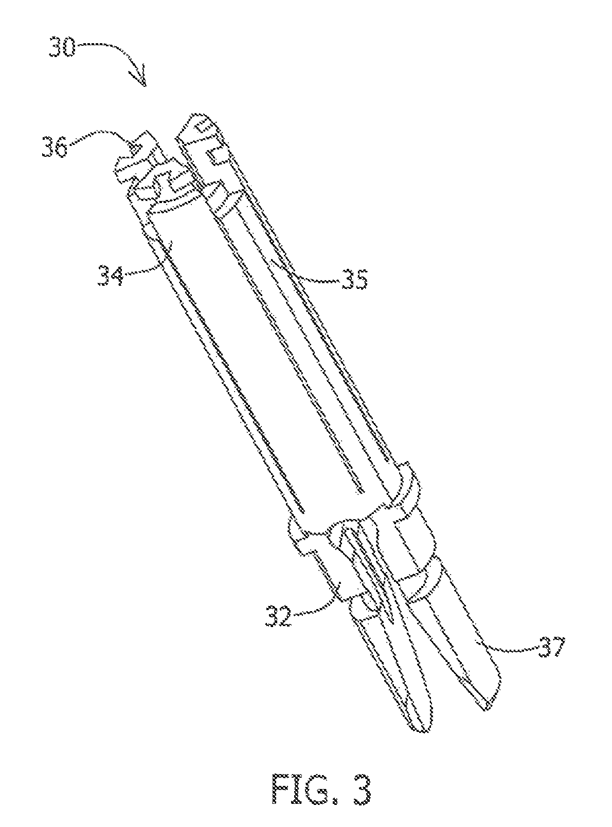
FIG. 1 is a perspective view of the stent-mounted valve, where the stent is a wire-based structure;
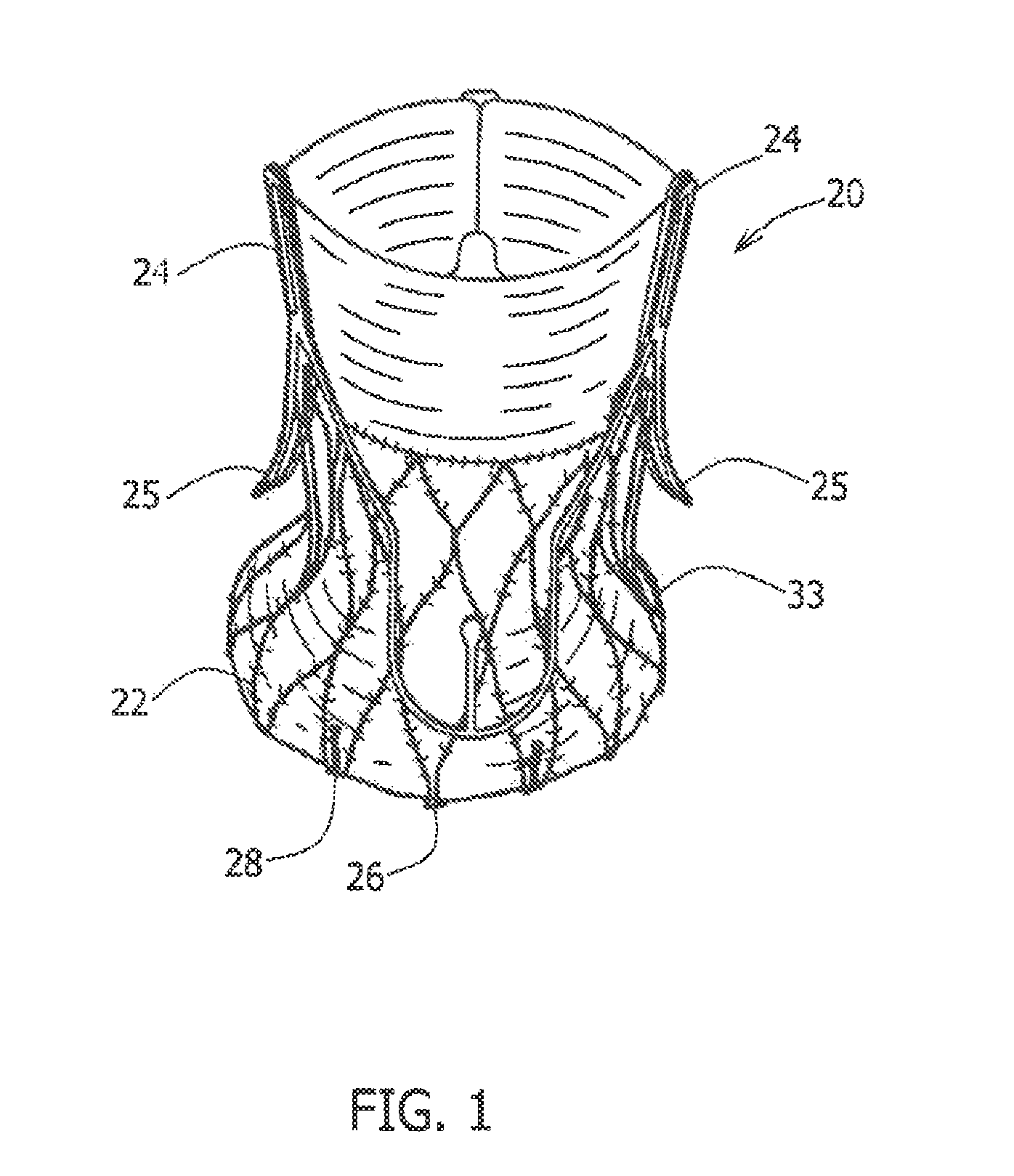
FIG. 2 is an enlarged, perspective view of a three-pronged loading tool in its natural, expanded state:
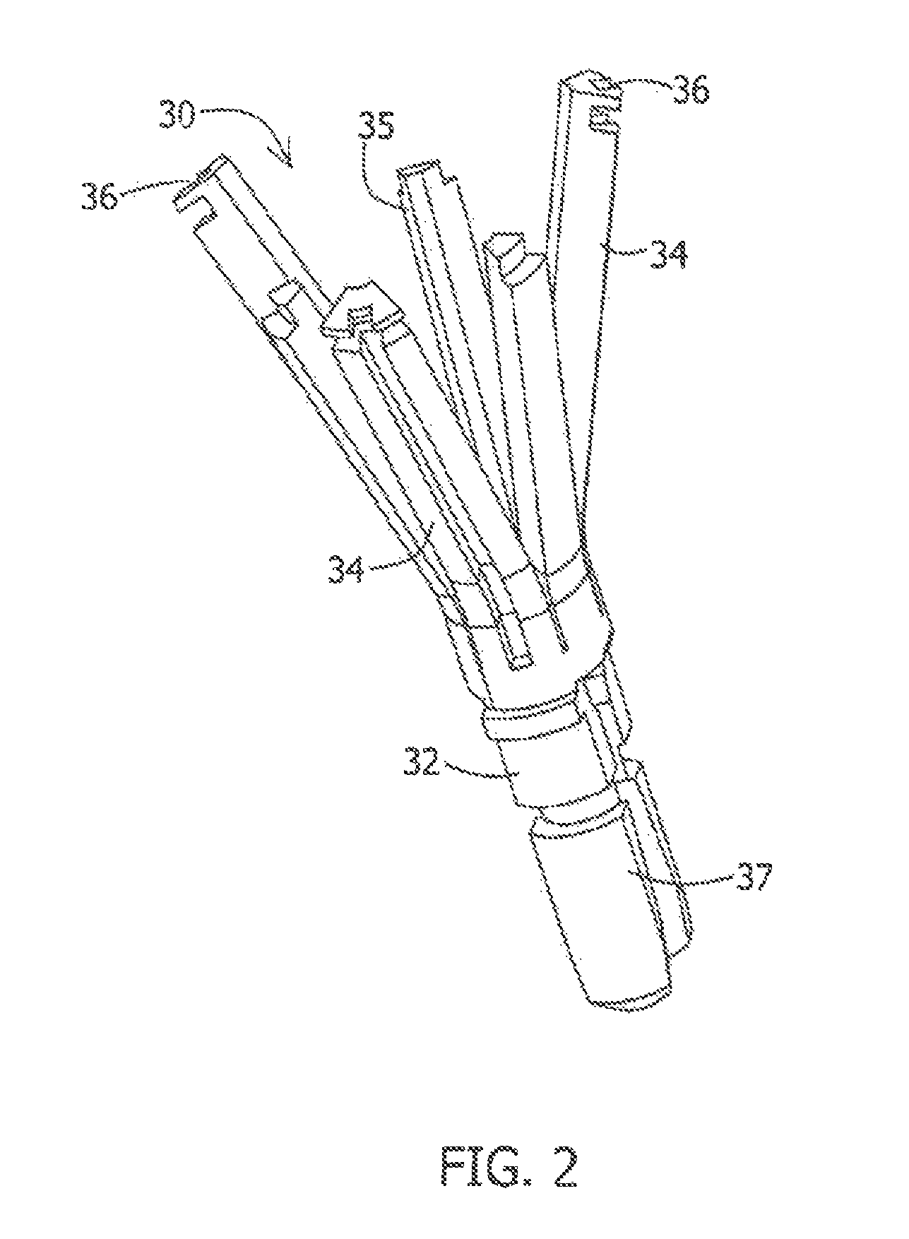
FIG. 3 is an enlarged view of a three-pronged loading tool, shown in its collapsed state;
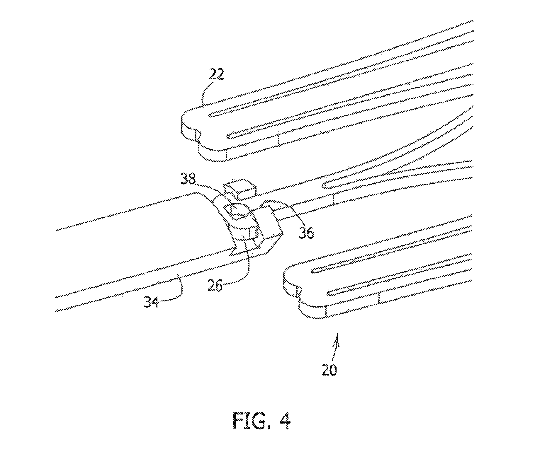
FIG. 4 is a close-up, detailed view showing attachment of the loading tool of FIGS. 2 and 3 to a self-expanding stent;
FIG. 5 is a close-up view of a portion of a self-expanding wire stent and a loading tool;
FIG. 6 is a schematic view, in partial cross-section, of a loading tool attached to a stent-mounted valve, a generally converging-shape crimping tool, in wide-mouthed bottle storage packaging;
FIG. 7A is a partial cross-sectional view of a bottle storage packaging containing a stent-mounted valve;
FIG. 7B is a partial cross-sectional view of three-prong loading tool attached to the stent-mounted valve of FIG. 7A by the user;
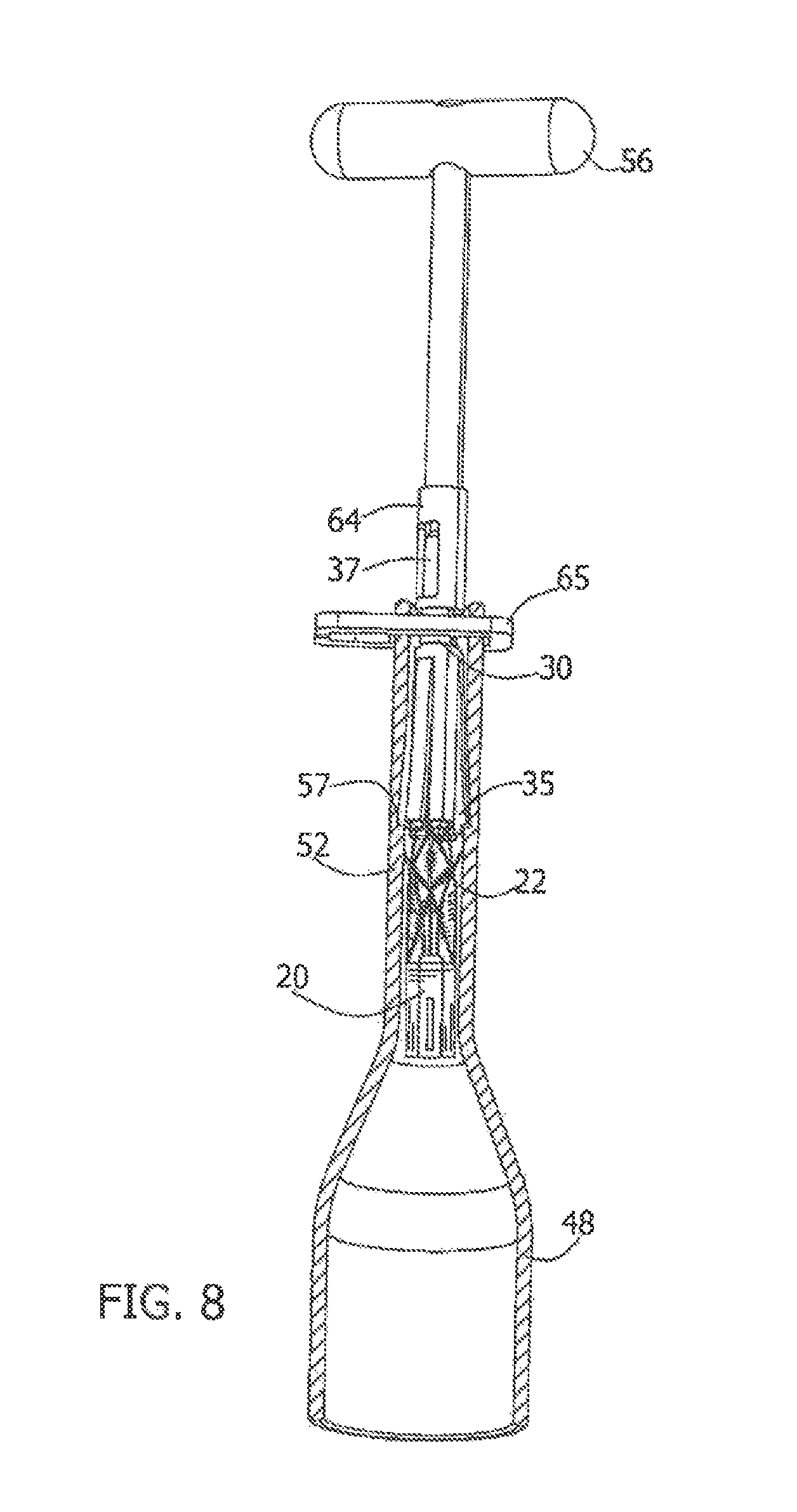
FIG. 8 is a partial cross-sectional view illustrating the loading tool and stent-mounted valve of FIG. 6 after the stent-mounted valve and the loading tool have been crimped inside of the converging-shape crimping tool;
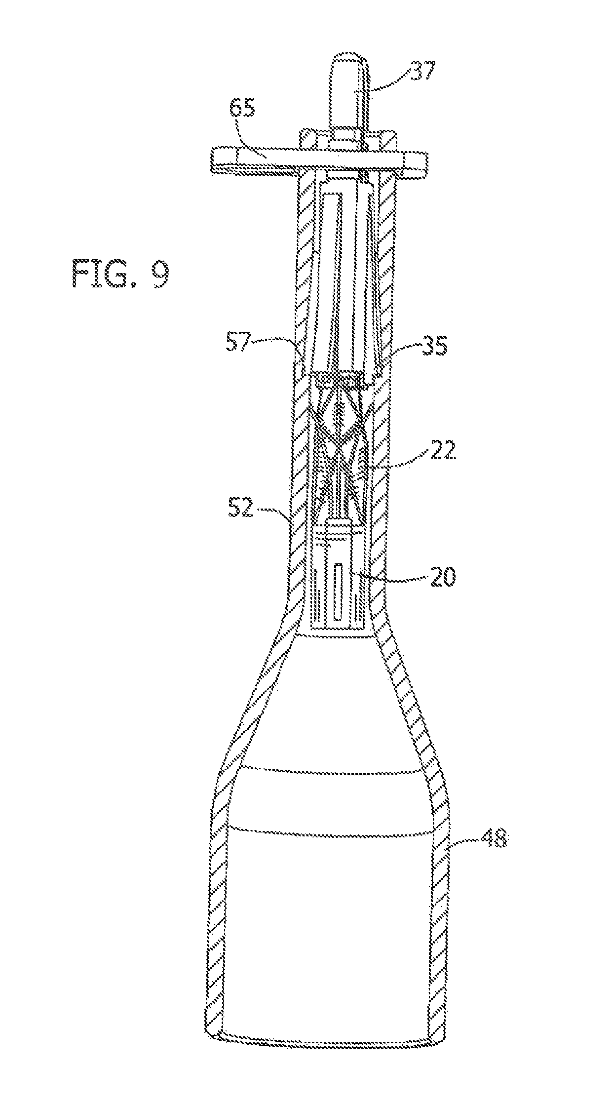
FIG. 9 is a partial cross-sectional view illustrating the loading tool and stent-mounted valve of FIG. 6 after the handle has been detached from the top of the loading tool;
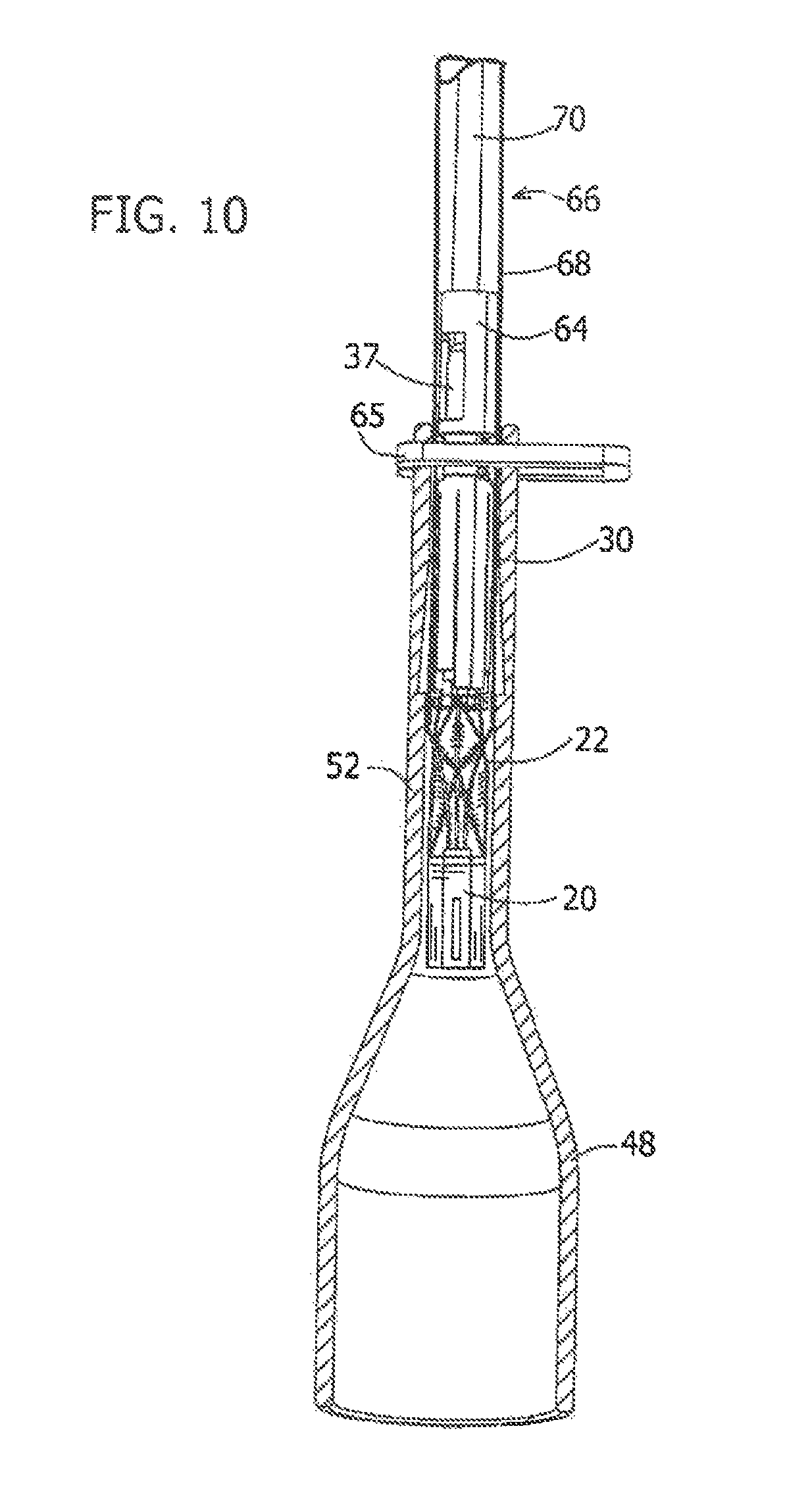
FIG. 10 is a partial cross-sectional view illustrating the loading tool and stent-mounted valve of FIG. 6, after the catheter has been attached to the sipper end of loading tool;
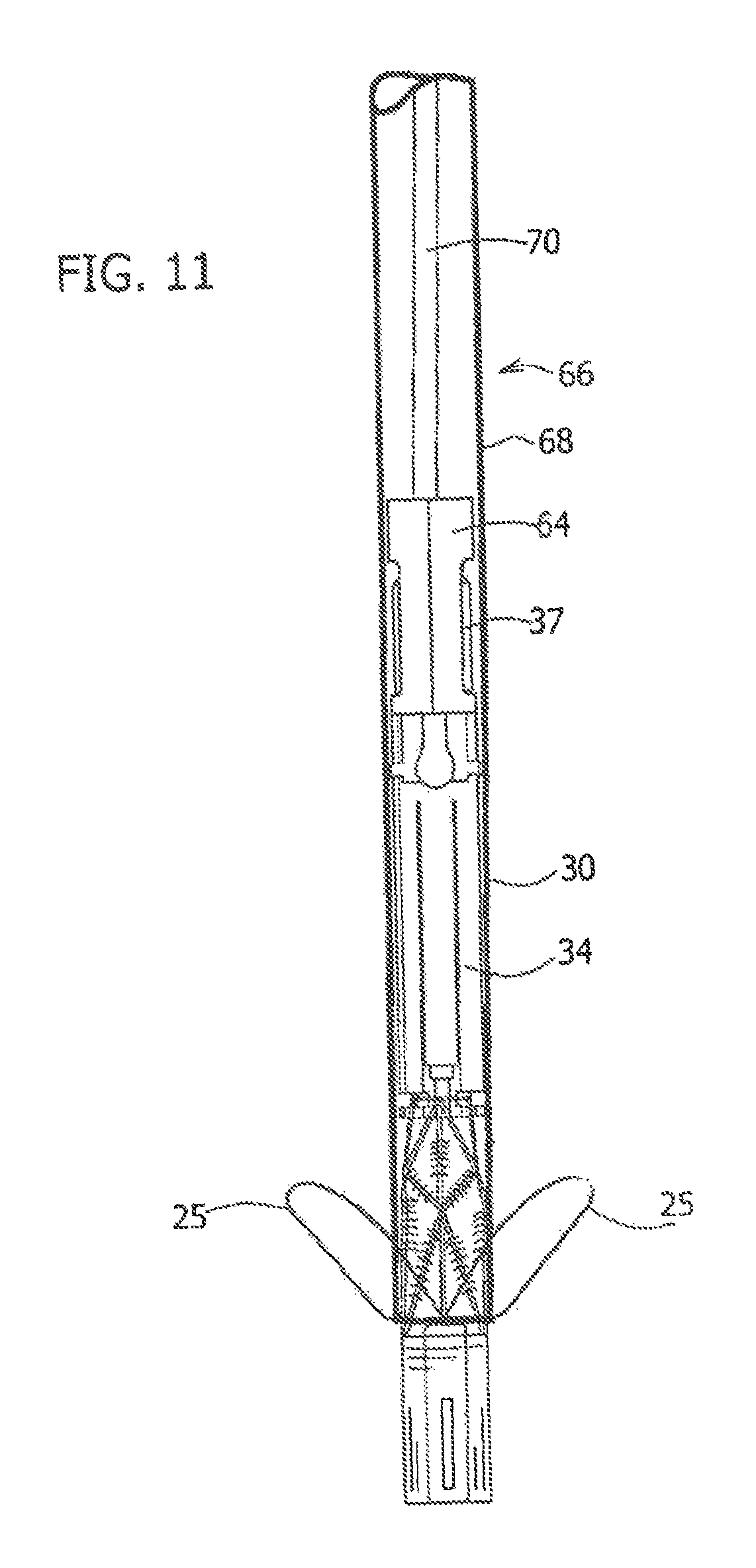
FIG. 11 is a side view illustrating the loading tool and stent-mounted valve of FIG. 6, after the loading tool and valve have been retracted into the catheter delivery tube and the converging-shape crimping tube has been removed; and
FIG. 12 is a schematic view illustrating the loading tool and the stent-mounted valve of FIG. 6, after the stent-mounted valve has been released from the catheter delivery tube during the implantation procedure.
DETAILED DESCRIPTION OF THE PREFERRED EMBODIMENTS
FIG. 1 is a perspective view of a self-expanding stent-mounted valve (20). Stent-mounted valve (20) may be of several types as is known to those skilled the art, but in the example of FIG. 1, the stem-mounted valve (20) is shown as a wire structure having a wire-mesh, expandable frame stent (22). Engagement arms (25) are typically configured to engage and/or rest against floors of aortic sinuses, to position the prosthetic valve assembly (20) in the native valve, and to apply an axial force directed towards the left ventricle. A more detailed description of our basic stent mounted valve is provided in U.S. patent application Ser. No. 11/024,908, filed Dec. 30, 2004, published as No. 2006/0149360, to Schwammenthal, et al., herein incorporated by reference in its entirety.
FIGS. 2 and 3 provide enlarged views of a three-prong loading tool (30) in an open state and in a closed state, respectively. The loading tool (30) has a base (32) and three prongs (34), extending therefrom for facilitating connection to the stent-mounted valve using the notches (36) found at the prong tips. Three additional short prongs (35) extend from base (32) between prongs (34). Short prongs (35) serve to secure the positioning of loading tool (30) inside of a crimping tool, in a manner to be described further below. Base (32) is provided with a pusher connector or base connectors (37) for coupling to a catheter assembly component, e.g., an inner shaft.
It is appreciated that prongs (34) in this variation should be sufficiently flexible to allow the tips to be squeezed together (as shown in FIG. 3) and allow attachment to a stent-mounted valve. The prongs (34) may have a comparatively stiff section adjacent the prong tips and a comparatively more flexible section, a hinge-like area opposite the prong tips to allow the desired movement in attachment to the stent. Alternatively, the desired flexibility of the prongs (34) may be designed into the length of the prongs (34), i.e., each increment of a prong bends in a similar amount, thereby eliminating the hinge area of the earlier discussed variation. Other variations of prong flexibility, e.g., variation of the prong flexibility from a higher value at the tip to a lower flexibility at the base, are also suitable. Otherwise, prongs (34) should be sufficiently rigid to allow them to form a portion of the catheter delivery system.
In the variation illustrated, each prong (34) is provided with a radially outwardly facing notch (36) at its tip or distal end for connection to the stent of a stent-mounted valve such as those shown in FIG. 1. Loading tool (30) may be formed from suitable, elastic, medically safe polymeric, metallic, or combination materials which preserve a high degree of integrity during the procedure. Specifically, unless breakage or deformation is desired as a component of a particular design, the materials should not otherwise break or become deformed when in use. Suitable materials include metals or alloys such as many of the stainless steels, super-elastic alloys such as nitinol, titanium and titanium alloys, cobalt chromium alloys, and the like. Suitable materials also include polymers such as many of the Nylons, polycarbonates, polyimides, polyketones (such as polyetheretherketone (PEEK), polyetherketoneketone (PEKK), polyetherketone (PEK), polyetherketoneetherketoneketone (PEKEKK), and polyetheretherketoneketone (PEEKK), and generally a polyaryletheretherketone), and the like. Suitable polymeric materials, whether thermosets or thermoplastics, may be filled with, e.g., glass fibers, carbon fibers, polymeric fibers, ceramic fibers, and the like.
The design specifics of the loading tool (30) may be altered from those illustrated in the drawings for connecting to the stent (22), so long as the function of the tool is preserved. For instance, in the variation shown in FIGS. 2 and 3, the loading tool (32) includes prongs (34) with notches (36) that open outwardly, the prongs switching from an open state allowing attachment to the stent, to a closed state, allowing loading into the catheter delivery tube. With appropriate modification, the notches may, however, open inwardly or be open at the end of the prongs. However, a suitable loading tool is simply one having a connector or connector region permitting controllable connection to the stent, facilitating compression (or crimping) of the stent-mounted valve, loading of the stent-mounted valve into a catheter delivery tube, and controllably releasing the stent-supported valve at the delivery site.
As mentioned above, the depicted loading tool (30) includes three prongs (34). This number of prongs (34) may be chosen as a balance between providing adequate support of the stent during the crimping step and providing the minimum number of suitably functional mechanical components. Of course, this variation of the loading tool may include any other suitable number of prongs such as, but not limited to, two, four, five or six. In each case, the stent-mounted valve would typically be provided with a corresponding number of connecting members (or connecting regions) in the slant to allow cooperative connection therebetween. For example, in variations where the loading tool has three prongs, the stent generally would also have three prongs. However, the stent may be designed to include more than three connection members, sites, or regions to ease the step of connection between the loading tool and the sent by providing additional connection sites.
FIG. 4 is an enlarged, detailed view showing the connection of the loading tool of FIGS. 2 and 3 to a stent-mounted valve. Notch (36) of prong (34) connects to the stent connector (26) of stent (22) in the manner illustrated, with connector (26) seated inside of notch (36). The sleet connector (26) radially slides into notch (36). However, the notch (36) is configured so that the stem connector (26) does not substantially move axially in either direction. This configuration means that the connection is firm whether the loading tool is being used to pull the stent-mounted valve through the crimping tool or to push the crimped stent-mounted valve through the delivery catheter.
The loading tool (30) has a longitudinal axis and the at least one connector, in this case, comprising the prong(s) (34) is configured to removably attach to the stent (22) of the stent valve (20).
The depicted stent connector (26) includes an aperture (38) that is not necessary for the connection shown in FIG. 4, but may be used in conjunction with other prong variations, such as that shown in FIG. 5.
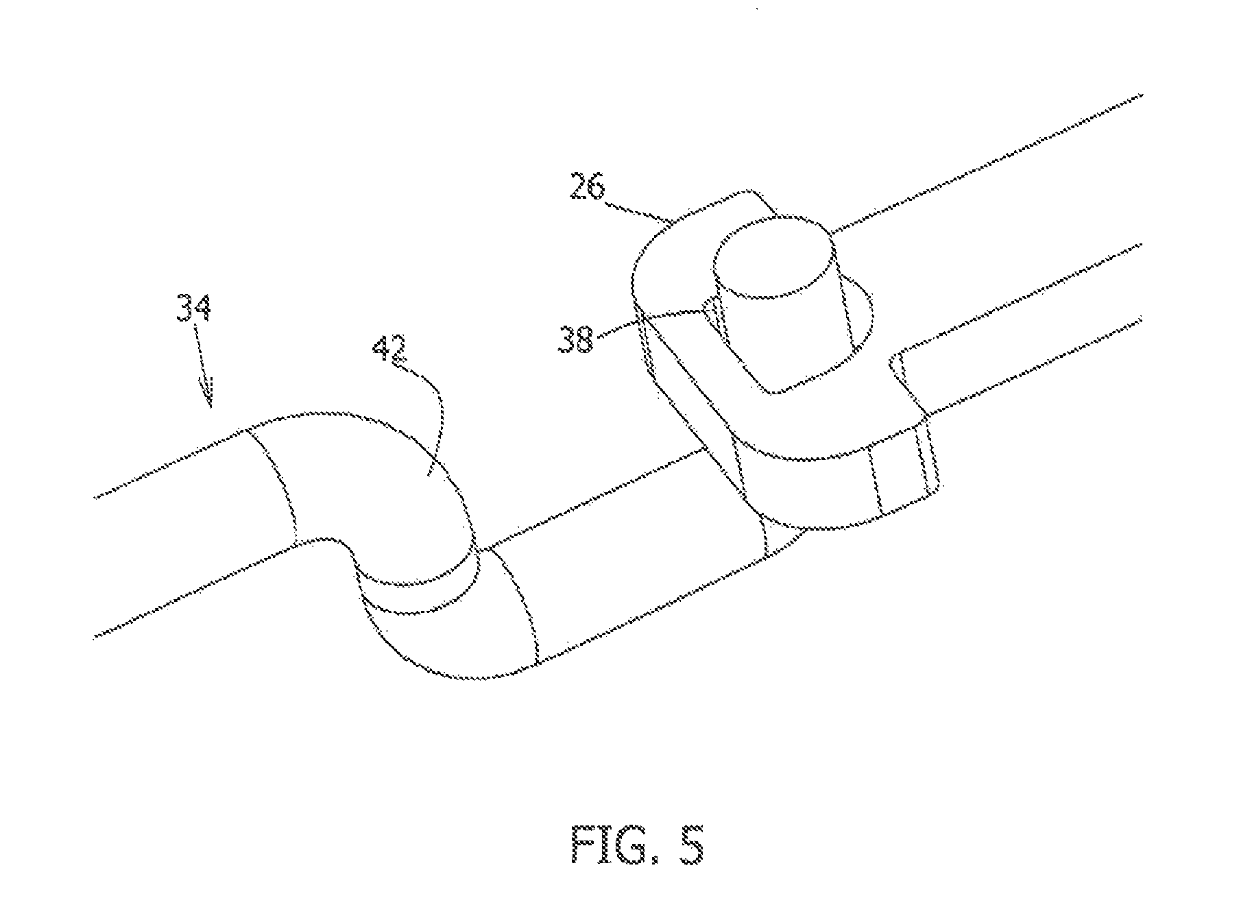
FIG. 5 is an enlarged, detailed view of an alternative connecting prong (34). In this variation, the prong (34) is provided with a hook member (42) at its distal end. The distal tip of the hook (42) passes through the aperture (38) in the stent connector (26). As is the case with prong variation discussed with regard to FIG. 3, the distal tip of the hook (42) prevents substantial, axial movement between the stent and the loading tool, but allows radial movement between the prong (34) and the stent valve during engagement and implantation of the valve.
The connection between the stent and the loading tool allows for the stent-mounted valve to be crimped and easily loaded into a catheter delivery tube, together with the loading tool. The depicted loading tools employ prongs having outward-facing notches. This means that the loading tool is placed inside the stent and the prongs grasp the stent from its interior. For those variations using a self-expanding stent, delivery of the stent-mounted valve allows the stent to undergo self-expansion. The stent expands away from the loading tool. This could be characterized as automatic disconnection of the stent from the loading tool.
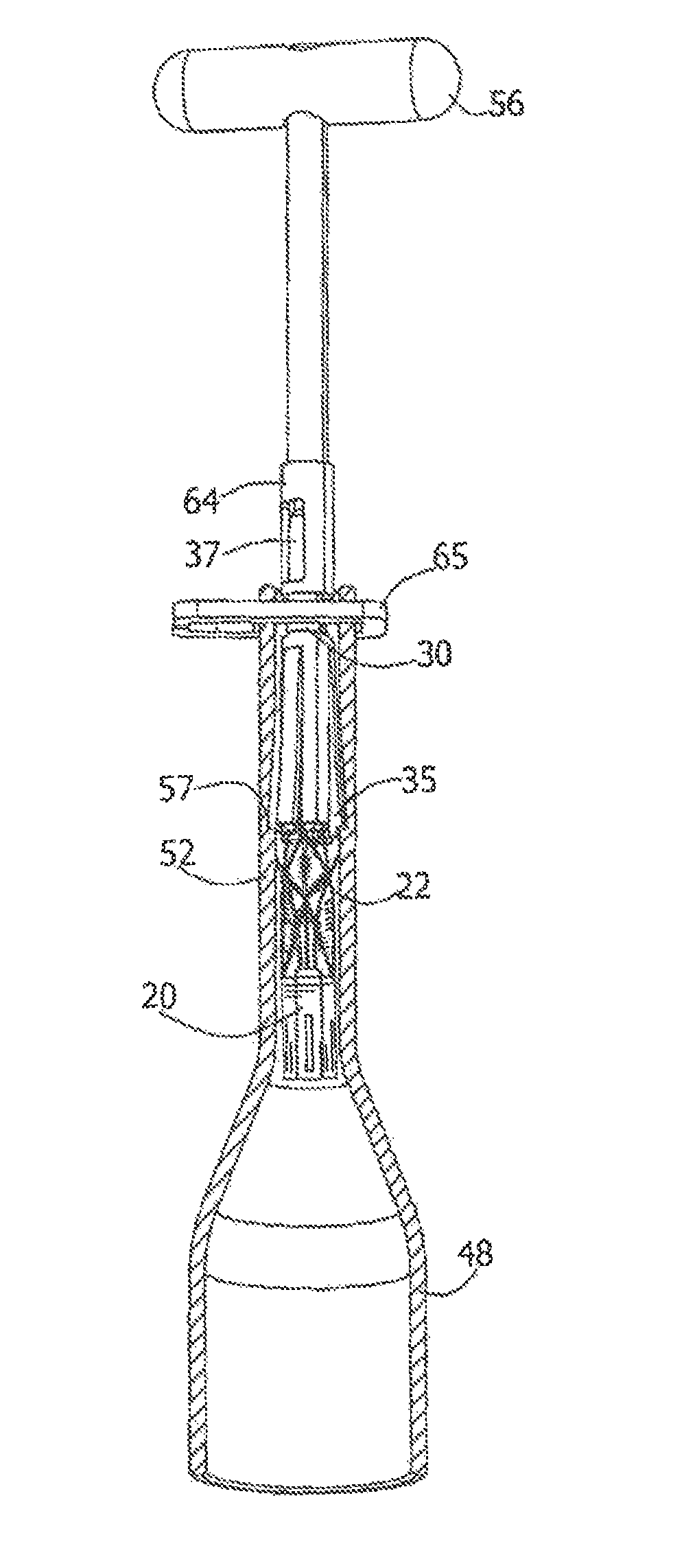
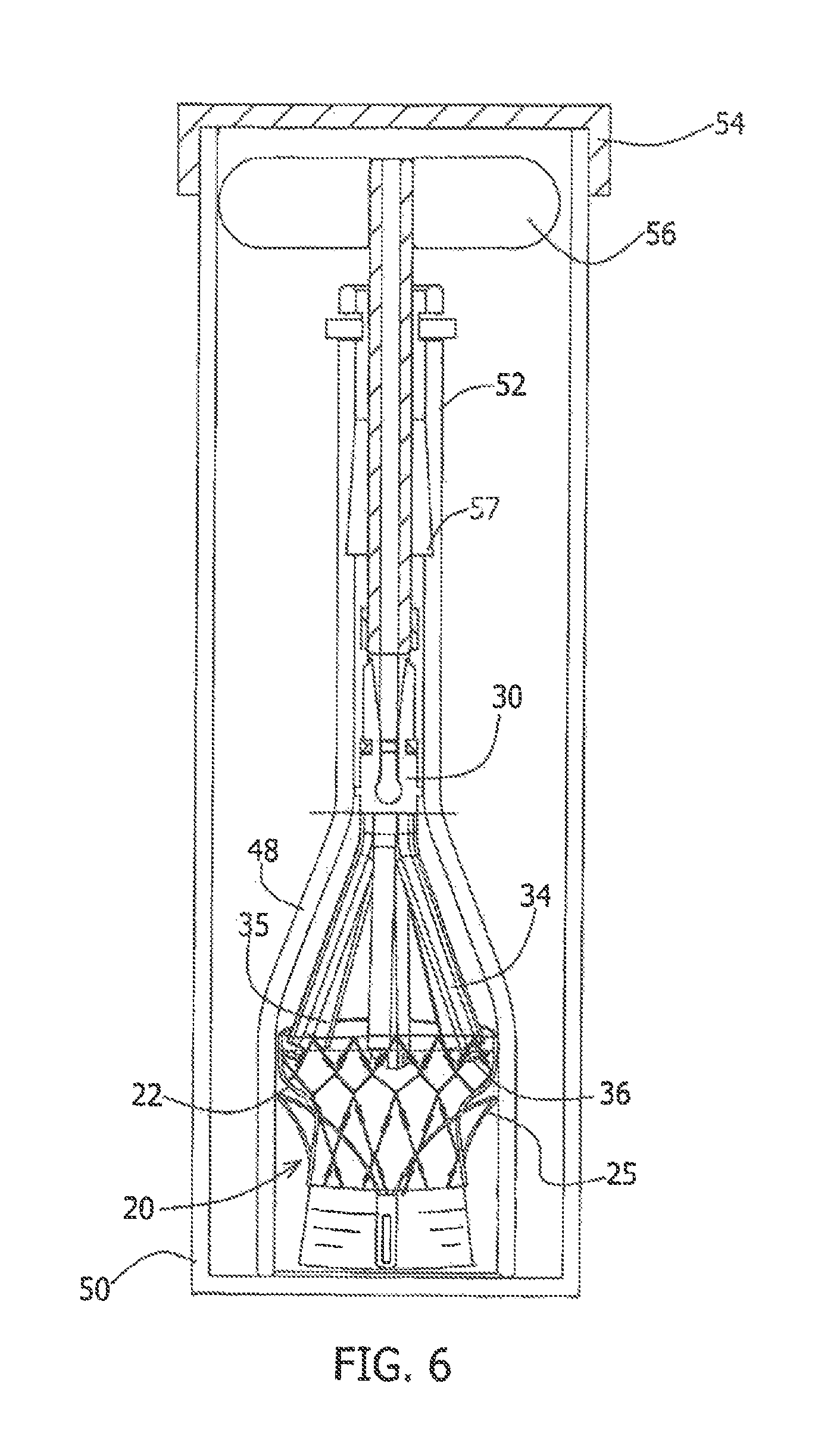
FIG. 6 shows a partial cross-section of an assembly useful as a self-contained kit suitable for commercial delivery to a surgical user, e.g., a hospital, clinic, surgical suite, physician, etc. In addition to the assembly described below, additional exterior packaging and written instructions may be included as necessary or appropriate. In any case, the assembly comprises a loading tool (30) attached to (or attachable to) a stent-mounted valve (20). A generally converging-shape (or converging diameter) crimping tool (48) substantially surrounds the loading tool (30) and valve (20). These components are all included within a wide-mouthed bottle storage container (50) serving as packaging for the assembly. The crimping tool (48) may have any suitable hollow, generally converging shape that compresses the stent-mounted valve (20) as it moves through the interior of the crimping tool (48).
Stent-mounted valve (20) is shown as sitting at the bottom of bottle storage container (50). In the example illustrated, three-prong loading tool (30) is attached to stent (22) of stent-mounted valve (20) by a cooperative connection in which the stent connector (26) slides radially into notch (36) of prong (34) of loading tool (30), as shown in FIG. 4. Stent-mounted valve (20) and attached loading tool (30) are situated within converging-shape crimping tool (48). Bottle delivery or storage container (50) is filled with a sterile, non-volatile preservative, a fluid, commonly glutaraldehyde. The glutaraldehyde should be washed from the crimped components after their removal from the delivery and storage container (50).
After any exterior packaging and the top (54) are removed storage container (50), a user (even a user wearing sterile disposable gloves) can easily remove the components from the storage container (50) by gripping the crimping tool (48) and handle (56). The handle (56) is removably connected to loading tool (30). Pulling handle (56) with respect to the crimping tool (48) draws the stent-mounted valve (20) and loading tool (30) upwards through that converging-shape crimping tool (48). The action crimps stent-mounted valve (20) and compresses prongs (34, 35) of loading tool (30) as these components pass into and through the narrow neck (52) of converging-shape crimping tool (48).
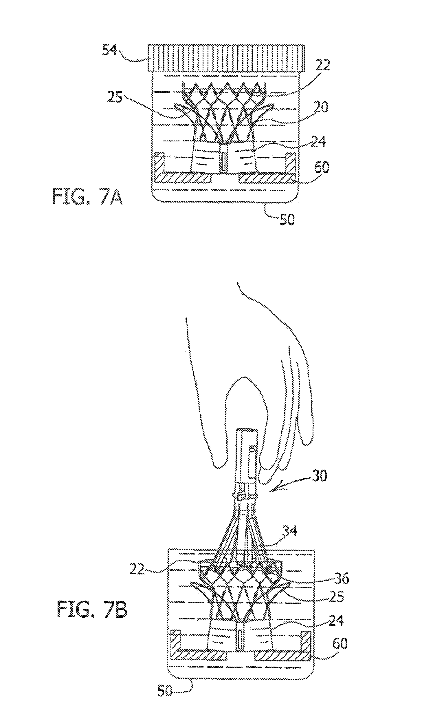
FIGS. 7A and 7B show alternative delivery packaging for the stent-mounted valve (20). In this variation, loading tool (30) and the converging shape crimping tool (48) are provided separately from the stent-mounted valve (20). In this variation, the stent-mounted valve (20) is enclosed in closed packaging, storage container (50) having closure or lid (54). The storage container (54) is typically filled with a liquid, e.g., comprising a preservative such as glutaraldehyde. The exemplified stent mounted valve (20) is shown having stent (22) with strut supports (24). A base (60) may be provided in the storage container (50) for supporting stent-mounted valve (20) in the liquid medium.
The various disclosed devices and combinations are also useful for other types of expandable stents, stent/valve combinations, and expandable prosthetics that are to be collapsed for delivery, delivered via a transcatheter procedure, and expanded at or before delivery.
In the variation shown in FIGS. 7A and 7B, to remove the stent-mounted valve (20) from the packaging, the user first removes cover (54) from storage container (50). The user the grasps loading tool (30) and slightly compresses prongs (34) inward and aligns the notches (36) of prongs (34) with the corresponding stem connectors (26) or regions of stent (22) such that when the prongs (34) are released in a controlled manner, stent (22) becomes connected to loading tool (30), as seen in FIG. 7B.
As noted above, prior to loading into the catheter delivery tube, the stent-mounted valve (20) may be washed to remove the preservative.
FIGS. 8-11 show the operation of the components, particularly the loading tool (30), stent-mounted valve (20), and converging-shape crimping tool (48), as they are taken from the integrated packaging (shown in FIG. 6) and placed in the catheter housing, and as the valve is implanted in the heart.
FIG. 8 is a schematic view illustrating the loading tool (30) and stent-mounted valve (20) after they have been removed from the packaging (50) a FIG. 6 and after the stent-mounted valve (20) and the loading tool (30) have been respectively, crimped and collapsed inside of the converging-shape crimping tool (48). The crimping of stent-mounted valve (20) and the collapsing of the prongs (34) of loading tool (30) are accomplished by pulling upwardly on handle (56). Handle (56) draws those components up and through converging-shape crimping tool (48) causing the prongs (34) of loading tool (30) to switch from an open to a closed configuration while remaining connected to stent-mounted valve (20).
Handle (56) is removably attached to loading tool (30) perhaps via a quick-release type mechanical coupling (64). However, other suitable coupler designs may be employed for removably connecting handle (56) to loading tool (30). A two position sliding clasp (65) or stopper is provided on the top of crimping tool (48). The sliding clasp (65) is shaped such that when in a first open position, handle (56) may be pulled upward. When the sliding clasp (65) is slid to a second (or closed) position, the sliding clasp (65) blocks upward movement of handle (56). Thus, following crimping of stent-mounted valve (20) by pulling it up into the neck (52) of crimping tool (48), the user slides sliding clasp (65) to the closed position and so prevents stent-mounted valve (20) and loading tool (30) from being prematurely released from crimping tool (48).
FIG. 8 also shows a circumferential indentation (57) in neck (52). This indentation (57) serves as a "safety stop," in the sense that it prevents the stent-mounted valve (20) from retracting into the larger diameter section a the crimping tool (48) after it has been pulled into the narrow neck (52). Specifically, as loading tool (30) and stent-mounted valve (20) are drawn upward through crimping tool (48), short prongs (35) of loading tool (30) engage indentation (57). This serves to prevent the stent mounted valve (20) from descending into the crimping tool (48), particularly after the handle (56) is removed, and to thereby prevent unwanted re-opening of stent-mounted valve (20). In sum, sliding clasp (65) prevents upward movement of loading tool (30) and valve (20); indentation (57) and short prongs (35) prevent downward movement of loading tool (30) and valve (20).
As is shown in FIG. 9, handle (56) is detached from loading tool (30) following crimping of stent-mounted valve (20) and loading tool (30) and subsequent closing of sliding clasp (65).
As illustrated in FIG. 10, loading tool (30) is then attached to a delivery catheter (66), comprising a catheter delivery tube (68) and an inner shaft (70) that extends coaxially through the interior a catheter delivery tube (68) to the loading tool (30). A mechanical coupling (64) connects the pusher or base connector (37) of loading tool (30) to inner shaft (70) of delivery catheter (66). Inner shaft (70) has the dual function of pulling the loading tool (30)/valve (20) into the catheter tube (68) and pushing the valve (20) our of the catheter tube (68) at implantation due to the relative motion between the inner shaft and the delivery tube. Said another way: backward movement of shaft (70) relative to the catheter delivery tube (68) causes loading tool (30) and stent-mounted valve (20) to be drawn out of crimping tool (48) and into catheter delivery tube (68). The loading tool (30) and stent-mounted valve (20) remain crimped or collapsed after entering the catheter delivery tube (68). The crimping tool (48) is then released and may be discarded. At this juncture, loading tool (30) and stent-mounted valve (20) are then retracted further into delivery catheter (66) by shaft (70). The assembly is then ready for passage through another catheter (or "outer tube") to the implantation site in the heart.
In FIG. 11, engagement arms (25) are shown to be external to catheter tube (68) during the passage of the stent-mounted valve (20) to the delivery site. During implantation, the delivery catheter (66) is advanced over a guidewire until the distal tip of the stent-mounted valve (20) and the engagement arms (25) pass through the native aortic valve. The delivery catheter (66) is then slightly withdrawn to flare the engagement arms (25) laterally into the valve sinuses. At this point, the stent is still in a compressed state in the catheter delivery tube (68).
Subsequent retraction of the catheter delivery tube (68), while maintaining the stent-mounted valve (20) stationary using the inner shaft (70), causes release of stent-mounted valve (20) and its placement and opening within the native heart valve orifice. The releasing and opening of the stent-mounted valve (20) causes the stent (22) to expand away from and be automatically disconnected from the still-compressed loading tool (30), as seen in FIG. 12. As mentioned above, the prongs (34) of the loading tool (30) reside in the interior of the stent (22), and when the stent (22) opens, the stent connectors readily exit the notches (36) formed in the prongs (34) of the loading tool (30).
Having described the invention with regard to certain specific embodiments thereof, it is to be understood that the description is not meant as a limitation, since further modifications may now suggest themselves to those skilled is the art, and it is intended to cover such modifications as fall within the scope of the appended claims.
* * * * *
D00000
D00001
D00002
D00003
D00004
D00005
D00006
D00007
D00008
D00009
D00010
D00011
D00012
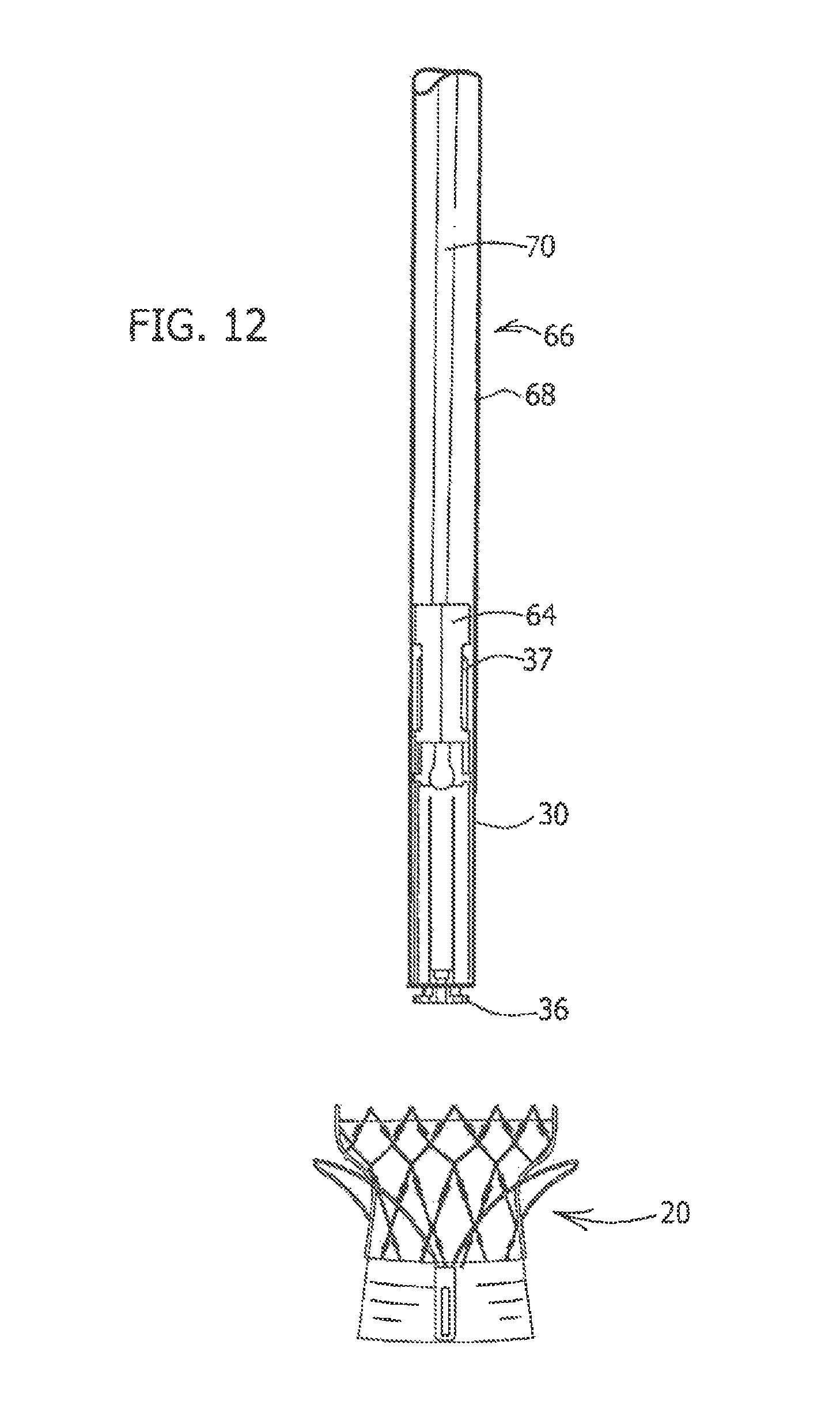
XML
uspto.report is an independent third-party trademark research tool that is not affiliated, endorsed, or sponsored by the United States Patent and Trademark Office (USPTO) or any other governmental organization. The information provided by uspto.report is based on publicly available data at the time of writing and is intended for informational purposes only.
While we strive to provide accurate and up-to-date information, we do not guarantee the accuracy, completeness, reliability, or suitability of the information displayed on this site. The use of this site is at your own risk. Any reliance you place on such information is therefore strictly at your own risk.
All official trademark data, including owner information, should be verified by visiting the official USPTO website at www.uspto.gov. This site is not intended to replace professional legal advice and should not be used as a substitute for consulting with a legal professional who is knowledgeable about trademark law.