Protective enclosure for encasing an electronic device
Martinez , et al. Ja
U.S. patent number 10,178,902 [Application Number 15/354,719] was granted by the patent office on 2019-01-15 for protective enclosure for encasing an electronic device. This patent grant is currently assigned to Otter Products, LLC. The grantee listed for this patent is OTTER PRODUCTS, LLC. Invention is credited to Oscar Lopez, Alfonso Martinez, Stephen James McFadden.


View All Diagrams
| United States Patent | 10,178,902 |
| Martinez , et al. | January 15, 2019 |
Protective enclosure for encasing an electronic device
Abstract
A protective enclosure for an electronic device includes a top member adapted to be removably coupled to a bottom member to enclose the electronic device. A first back engagement feature is disposed on an inside surface of a perimeter wall portion of the bottom member, and the first back engagement feature is adapted to engage a first front engagement feature disposed on an inner perimeter wall of the top member to removably secure the top member to the bottom member. A second back engagement feature is disposed on an outside surface of the perimeter wall portion of the bottom member, and the second back engagement feature is adapted to engage a second front engagement feature disposed on an outer perimeter wall of the top member to further removably secure the top member to the bottom member.
| Inventors: | Martinez; Alfonso (Escondido, CA), Lopez; Oscar (Descanso, CA), McFadden; Stephen James (San Diego, CA) | ||||||||||
|---|---|---|---|---|---|---|---|---|---|---|---|
| Applicant: |
|
||||||||||
| Assignee: | Otter Products, LLC (Fort
Collins, CO) |
||||||||||
| Family ID: | 61281751 | ||||||||||
| Appl. No.: | 15/354,719 | ||||||||||
| Filed: | November 17, 2016 |
Prior Publication Data
| Document Identifier | Publication Date | |
|---|---|---|
| US 20180064222 A1 | Mar 8, 2018 | |
Related U.S. Patent Documents
| Application Number | Filing Date | Patent Number | Issue Date | ||
|---|---|---|---|---|---|
| 15354522 | Nov 17, 2016 | ||||
| 62384314 | Sep 7, 2016 | ||||
| Current U.S. Class: | 1/1 |
| Current CPC Class: | G03B 17/08 (20130101); H04N 5/2252 (20130101); H04B 1/3888 (20130101); H04N 5/2254 (20130101); G03B 17/56 (20130101); A45C 13/008 (20130101); A45C 11/00 (20130101); A45C 2011/003 (20130101); A45C 2011/002 (20130101) |
| Current International Class: | A45C 13/00 (20060101); A45C 11/00 (20060101); A45F 5/00 (20060101); H04N 5/225 (20060101); H04B 1/3888 (20150101); G03B 17/08 (20060101); G03B 17/56 (20060101) |
| Field of Search: | ;206/320 |
References Cited [Referenced By]
U.S. Patent Documents
| 2392787 | January 1946 | Edmond |
| 2851670 | September 1958 | Senior |
| 3023885 | March 1962 | Kindseth |
| 3143384 | August 1964 | Senior |
| 3482895 | December 1969 | Becklin |
| 3665991 | May 1972 | Gillemot et al. |
| 3689866 | September 1972 | William |
| 3832725 | August 1974 | Cook |
| 3922477 | November 1975 | Glowacz |
| 4097878 | June 1978 | Cramer |
| 4298204 | November 1981 | Jinkins |
| 4312580 | January 1982 | Schwomma et al. |
| 4375323 | March 1983 | Inagaki et al. |
| 4383743 | May 1983 | Nozawa et al. |
| 4418830 | December 1983 | Dzung et al. |
| 4420078 | December 1983 | Belt et al. |
| 4546874 | October 1985 | Kirchhan |
| 4584718 | April 1986 | Fuller |
| 4649453 | March 1987 | Iwasawa |
| 4658956 | April 1987 | Takeda et al. |
| 4686332 | August 1987 | Greanias et al. |
| 4703161 | October 1987 | McLean |
| 4712657 | December 1987 | Myers et al. |
| 4733776 | March 1988 | Ward |
| 4762227 | August 1988 | Patterson |
| 4803504 | February 1989 | Maeno et al. |
| 4836256 | June 1989 | Meliconi |
| 4942514 | July 1990 | Miyagaki et al. |
| 4963902 | October 1990 | Fukahori |
| 4977483 | December 1990 | Perretta |
| 4994829 | February 1991 | Tsukamoto |
| 5002184 | March 1991 | Lloyd |
| D316932 | May 1991 | Escher |
| 5025921 | June 1991 | Gasparaitis et al. |
| D322165 | December 1991 | Lloyd |
| 5087934 | February 1992 | Johnson |
| 5092458 | March 1992 | Yokoyama |
| 5092459 | March 1992 | Uljanic et al. |
| 5175873 | December 1992 | Goldenberg et al. |
| 5177515 | January 1993 | Tsukamoto |
| 5219067 | June 1993 | Lima et al. |
| 5231381 | July 1993 | Duwaer |
| 5233502 | August 1993 | Beatty et al. |
| 5239323 | August 1993 | Johnson |
| 5239324 | August 1993 | Ohmura et al. |
| 5285894 | February 1994 | Kamata et al. |
| 5294988 | March 1994 | Wakabayashi et al. |
| 5305032 | April 1994 | Arai |
| 5336896 | August 1994 | Katz |
| 5360108 | November 1994 | Alagia |
| 5368159 | November 1994 | Doria |
| 5380968 | January 1995 | Morse |
| 5383091 | January 1995 | Snell |
| 5386084 | January 1995 | Risko |
| 5388691 | February 1995 | White |
| 5388692 | February 1995 | Withrow et al. |
| D365927 | January 1996 | Cho |
| 5505328 | April 1996 | Stribiak |
| 5508479 | April 1996 | Schooley |
| 5518802 | May 1996 | Colvin et al. |
| 5541813 | July 1996 | Satoh et al. |
| RE35318 | August 1996 | Warman |
| 5548306 | August 1996 | Yates et al. |
| 5583742 | December 1996 | Noda et al. |
| 5584054 | December 1996 | Tyneski et al. |
| 5586002 | December 1996 | Notarianni |
| 5590760 | January 1997 | Astarb |
| 5610655 | March 1997 | Wakabayashi et al. |
| 5613237 | March 1997 | Bent et al. |
| D378634 | April 1997 | LaPere |
| 5636101 | June 1997 | Bonsail et al. |
| 5660566 | August 1997 | Ohsumi |
| 5669004 | September 1997 | Sellers |
| 5681122 | October 1997 | Burke |
| 5707757 | January 1998 | Lee |
| 5713048 | January 1998 | Hayakawa |
| 5713466 | February 1998 | Tajima |
| 5845803 | December 1998 | Saito et al. |
| 5850915 | December 1998 | Tajima |
| 5907721 | May 1999 | Schelling et al. |
| 5946501 | August 1999 | Hayakawa |
| 5950816 | September 1999 | Reid |
| 5956291 | September 1999 | Nehemiah et al. |
| 5982520 | November 1999 | Weiser et al. |
| 5990874 | November 1999 | Tsumura et al. |
| D419297 | January 2000 | Richardson et al. |
| D419768 | February 2000 | Richardson et al. |
| 6031524 | February 2000 | Kunert |
| 6041924 | March 2000 | Tajima |
| D424035 | May 2000 | Steiner et al. |
| 6068119 | May 2000 | Derr et al. |
| 6092707 | July 2000 | Bowes |
| 6094785 | August 2000 | Montgomery et al. |
| 6128441 | October 2000 | Kamata et al. |
| 6132367 | October 2000 | Adair |
| 6201867 | March 2001 | Koike |
| D447634 | September 2001 | Snider |
| 6304459 | October 2001 | Toyosato et al. |
| 6311017 | October 2001 | Mori |
| 6313982 | November 2001 | Hino |
| 6317313 | November 2001 | Mosgrove et al. |
| 6349824 | February 2002 | Yamada |
| 6388877 | May 2002 | Canova et al. |
| 6396769 | May 2002 | Polany |
| 6398585 | June 2002 | Fukuda |
| 6415138 | July 2002 | Sirola et al. |
| 6445577 | September 2002 | Madsen et al. |
| 6447140 | September 2002 | Lu |
| 6456487 | September 2002 | Hetterick |
| D464196 | October 2002 | Parker |
| 6471056 | October 2002 | Tzeng |
| 6519141 | February 2003 | Tseng et al. |
| 6525928 | February 2003 | Madsen et al. |
| 6532152 | March 2003 | White et al. |
| 6536589 | March 2003 | Chang |
| 6571056 | May 2003 | Shimamura et al. |
| 6574434 | June 2003 | Matsuoto et al. |
| 6594472 | July 2003 | Curtis et al. |
| 6595608 | July 2003 | Minelli et al. |
| 6597865 | July 2003 | Negishi et al. |
| 6614423 | September 2003 | Wong et al. |
| 6614722 | September 2003 | Polany et al. |
| 6616111 | September 2003 | White |
| 6617973 | September 2003 | Osterman |
| 6625394 | September 2003 | Smith et al. |
| 6634494 | October 2003 | Derr et al. |
| 6636697 | October 2003 | Smith et al. |
| 6646864 | November 2003 | Richardson |
| 6659274 | December 2003 | Enners |
| 6665174 | December 2003 | Derr et al. |
| 6667738 | December 2003 | Murphy |
| 6669017 | December 2003 | Linihan |
| 6698608 | March 2004 | Parker et al. |
| 6721651 | April 2004 | Minelli |
| 6751552 | June 2004 | Minelli |
| 6760570 | July 2004 | Higdon |
| 6778388 | August 2004 | Minelli |
| 6785566 | August 2004 | Irizarry |
| 6819866 | November 2004 | Silva |
| 6822161 | November 2004 | Komatsu et al. |
| 6822640 | November 2004 | Derocher |
| 6844845 | January 2005 | Whiteside et al. |
| 6848930 | February 2005 | Fukuda |
| 6913201 | July 2005 | Wagner et al. |
| 6914774 | July 2005 | Albertini et al. |
| D507871 | August 2005 | DiMarchi et al. |
| 6953126 | October 2005 | Parker et al. |
| 6954405 | October 2005 | Polany et al. |
| 6955293 | October 2005 | Katsanevas |
| 6971517 | December 2005 | Chen |
| 6975888 | December 2005 | Buesseler et al. |
| 6980777 | December 2005 | Shepherd et al. |
| 6983130 | January 2006 | Chien et al. |
| 6987527 | January 2006 | Kossin |
| 6992659 | January 2006 | Gettemy |
| 6995976 | February 2006 | Richardson |
| D516807 | March 2006 | Richardson et al. |
| 7025274 | April 2006 | Solomon et al. |
| 7033215 | April 2006 | Kobayashi |
| 7046230 | May 2006 | Zadesky et al. |
| 7050712 | May 2006 | Shimamura |
| 7050841 | May 2006 | Onda |
| 7054441 | May 2006 | Pletikosa |
| 7061762 | June 2006 | Canova et al. |
| 7069063 | June 2006 | Halkosaari et al. |
| 7072467 | July 2006 | Ono |
| 7082264 | July 2006 | Watanabe et al. |
| 7085542 | August 2006 | Dietrich et al. |
| 7106959 | September 2006 | Sato |
| D530079 | October 2006 | Thomas et al. |
| 7146701 | December 2006 | Mahoney et al. |
| 7158376 | January 2007 | Richardson et al. |
| 7180735 | February 2007 | Thomas et al. |
| 7194086 | March 2007 | Pletikosa |
| 7194202 | March 2007 | Funahashi et al. |
| 7194291 | March 2007 | Peng |
| D542524 | May 2007 | Richardson et al. |
| 7230823 | June 2007 | Richardson et al. |
| 7236588 | June 2007 | Gartrell |
| 7255228 | August 2007 | Kim |
| 7263032 | August 2007 | Polany et al. |
| 7312984 | December 2007 | Richardson et al. |
| 7327841 | February 2008 | Schreiber et al. |
| 7341144 | March 2008 | Tajiri et al. |
| 7343184 | March 2008 | Rostami |
| 7352961 | April 2008 | Watanabe et al. |
| 7362570 | April 2008 | Su |
| 7365281 | April 2008 | Yamaguchi et al. |
| 7366555 | April 2008 | Jokinen et al. |
| 7369881 | May 2008 | Tsujimoto |
| 7389869 | June 2008 | Mason |
| 7400917 | July 2008 | Wood et al. |
| D574819 | August 2008 | Andre et al. |
| D575056 | August 2008 | Tan |
| 7409148 | August 2008 | Takahashi et al. |
| 7418278 | August 2008 | Eriksson et al. |
| 7428427 | September 2008 | Brunstrom et al. |
| 7436653 | October 2008 | Yang et al. |
| D581421 | November 2008 | Richardson et al. |
| 7448908 | November 2008 | Iwahori et al. |
| D582149 | December 2008 | Tan |
| 7464813 | December 2008 | Carnevali |
| 7464814 | December 2008 | Carnevali |
| 7495659 | February 2009 | Marriott et al. |
| 7495895 | February 2009 | Carnevali |
| 7499040 | March 2009 | Zadesky et al. |
| 7502550 | March 2009 | Ariga |
| 7511956 | March 2009 | Tomioka et al. |
| 7525792 | April 2009 | Yokote |
| 7535799 | May 2009 | Polany et al. |
| D593319 | June 2009 | Richardson et al. |
| 7555325 | June 2009 | Goros |
| D597089 | July 2009 | Khan et al. |
| 7558594 | July 2009 | Wilson |
| 7594576 | September 2009 | Chen et al. |
| 7609512 | October 2009 | Richardson et al. |
| D603603 | November 2009 | Laine et al. |
| 7613386 | November 2009 | Shimamura |
| 7623898 | November 2009 | Holmberg |
| D605850 | December 2009 | Richardson et al. |
| D606751 | December 2009 | Andre et al. |
| 7630746 | December 2009 | Holmberg |
| 7653292 | January 2010 | Yamaguchi et al. |
| 7663878 | February 2010 | Swan et al. |
| 7663879 | February 2010 | Richardson et al. |
| D611478 | March 2010 | Richardson et al. |
| 7679674 | March 2010 | Nishizawa |
| 7688580 | March 2010 | Richardson et al. |
| 7697269 | April 2010 | Yang et al. |
| D616430 | May 2010 | Fathollahi |
| 7733642 | June 2010 | Liou et al. |
| 7755975 | July 2010 | Pettersen et al. |
| D622716 | August 2010 | Andre et al. |
| 7772507 | August 2010 | Orr et al. |
| 7775354 | August 2010 | Latchford et al. |
| 7782610 | August 2010 | Diebel et al. |
| 7787756 | August 2010 | Funahashi et al. |
| D623180 | September 2010 | Diebel |
| D624532 | September 2010 | Huskinson |
| 7789228 | September 2010 | Zenzai |
| 7789696 | September 2010 | Umei et al. |
| 7801425 | September 2010 | Fantone et al. |
| D624908 | October 2010 | Huskinson |
| D624909 | October 2010 | Huskinson |
| 7850032 | December 2010 | Carnevali et al. |
| 7854434 | December 2010 | Heiman et al. |
| 7889489 | February 2011 | Richardson et al. |
| 7907394 | March 2011 | Richardson et al. |
| 7926818 | April 2011 | Isono |
| 7933122 | April 2011 | Richardson et al. |
| 7936566 | May 2011 | Shigyo et al. |
| 7941196 | May 2011 | Kawasaki et al. |
| 7944697 | May 2011 | Hata et al. |
| 7975870 | July 2011 | Laule et al. |
| 7978092 | July 2011 | Osaka |
| 7993071 | August 2011 | Clawson |
| 8004835 | August 2011 | Conti et al. |
| 8006020 | August 2011 | Minoo |
| D644636 | September 2011 | Richardson et al. |
| 8024015 | September 2011 | Araki et al. |
| 8031472 | October 2011 | Bicket et al. |
| 8032194 | October 2011 | Liu et al. |
| 8053668 | November 2011 | Lai et al. |
| 8068331 | November 2011 | Sauers et al. |
| 8089757 | January 2012 | Chen et al. |
| 8101859 | January 2012 | Zadesky |
| 8112130 | February 2012 | Mittleman et al. |
| 8138434 | March 2012 | Tang et al. |
| 8160657 | April 2012 | Perriello et al. |
| 8164899 | April 2012 | Yamaguchi et al. |
| 8167126 | May 2012 | Stiehl |
| 8191706 | June 2012 | Liu |
| 8204561 | June 2012 | Mongan et al. |
| 8223997 | July 2012 | Wilson, II et al. |
| 8245842 | August 2012 | Bau |
| 8251210 | August 2012 | Schmidt et al. |
| 8265264 | September 2012 | Yamaguchi et al. |
| 8269104 | September 2012 | Choraku et al. |
| 8286789 | October 2012 | Wilson et al. |
| 8295043 | October 2012 | Tai et al. |
| 8311595 | November 2012 | Takatsuka et al. |
| 8342325 | January 2013 | Rayner |
| 8373980 | February 2013 | Reber |
| 8393466 | March 2013 | Rayner |
| 8430240 | April 2013 | Kim |
| 8454101 | June 2013 | Kuo |
| 8520373 | August 2013 | Liu |
| 8526180 | September 2013 | Rayner |
| 8531824 | September 2013 | Rayner |
| 8531834 | September 2013 | Rayner |
| 8548541 | October 2013 | Rayner |
| 8564950 | October 2013 | Rayner |
| 8570737 | October 2013 | Rayner |
| 8584847 | November 2013 | Tages et al. |
| 8599547 | December 2013 | Richardson et al. |
| 8681103 | March 2014 | Cha et al. |
| 8708142 | April 2014 | Rayner |
| 8798675 | August 2014 | Salmon et al. |
| 8833379 | September 2014 | Kaplan |
| 8995126 | March 2015 | Rayner |
| 9276626 | March 2016 | Rayner |
| 2001/0040109 | November 2001 | Yaski et al. |
| 2002/0003584 | January 2002 | Kossin |
| 2002/0009195 | January 2002 | Schon |
| 2002/0065054 | May 2002 | Humphreys et al. |
| 2002/0071550 | June 2002 | Pletikosa |
| 2002/0079244 | June 2002 | Kwong |
| 2002/0085709 | July 2002 | Hsu |
| 2002/0090212 | July 2002 | Shimamura et al. |
| 2002/0122353 | September 2002 | Polany et al. |
| 2002/0136557 | September 2002 | Shimamura |
| 2002/0137475 | September 2002 | Shou et al. |
| 2002/0175096 | November 2002 | Linihan |
| 2002/0175901 | November 2002 | Gettemy |
| 2002/0193136 | December 2002 | Halkosaari et al. |
| 2002/0195910 | December 2002 | Hus et al. |
| 2003/0080947 | May 2003 | Genest et al. |
| 2003/0095374 | May 2003 | Richardson |
| 2003/0111366 | June 2003 | Enners |
| 2003/0118332 | June 2003 | Smith et al. |
| 2003/0118334 | June 2003 | Smith et al. |
| 2003/0128397 | July 2003 | Smith et al. |
| 2003/0223577 | December 2003 | Ono |
| 2004/0014506 | January 2004 | Kemppinen |
| 2004/0076415 | April 2004 | Silva |
| 2004/0089570 | May 2004 | Chien et al. |
| 2004/0120219 | June 2004 | Polany et al. |
| 2004/0121226 | June 2004 | Kaelin et al. |
| 2004/0188120 | September 2004 | Komatsu et al. |
| 2004/0195783 | October 2004 | Akagi et al. |
| 2004/0203502 | October 2004 | Dietrich et al. |
| 2004/0226836 | November 2004 | Schreiber et al. |
| 2005/0052425 | March 2005 | Zadesky et al. |
| 2005/0094024 | May 2005 | Sato |
| 2005/0110768 | May 2005 | Marriott et al. |
| 2005/0115852 | June 2005 | Funahashi et al. |
| 2005/0123161 | June 2005 | Polany et al. |
| 2005/0139498 | June 2005 | Goros |
| 2005/0167304 | August 2005 | Shimamura |
| 2005/0174727 | August 2005 | Thomas et al. |
| 2005/0181843 | August 2005 | Tsujimoto |
| 2005/0224508 | October 2005 | Tajiri et al. |
| 2005/0247584 | November 2005 | Lu |
| 2005/0279655 | December 2005 | Chen |
| 2005/0279661 | December 2005 | Hodges |
| 2006/0008261 | January 2006 | Watanabe et al. |
| 2006/0110146 | May 2006 | Ariga |
| 2006/0113173 | June 2006 | Matsumoto et al. |
| 2006/0255493 | November 2006 | Fouladpour |
| 2006/0274493 | December 2006 | Richardson et al. |
| 2007/0040931 | February 2007 | Nishizawa |
| 2007/0071423 | March 2007 | Fantone et al. |
| 2007/0074473 | April 2007 | Yamaguchi et al. |
| 2007/0086273 | April 2007 | Polany et al. |
| 2007/0109730 | May 2007 | Shigyo et al. |
| 2007/0110416 | May 2007 | Yamaguchi et al. |
| 2007/0115387 | May 2007 | Ho |
| 2007/0138920 | June 2007 | Austin et al. |
| 2007/0139873 | June 2007 | Thomas et al. |
| 2007/0146985 | June 2007 | Mick et al. |
| 2007/0158220 | July 2007 | Cleereman et al. |
| 2007/0171603 | July 2007 | Yang et al. |
| 2007/0184781 | August 2007 | Huskinson |
| 2007/0215663 | September 2007 | Chongson et al. |
| 2007/0241012 | October 2007 | Latchford et al. |
| 2007/0261976 | November 2007 | Anderson |
| 2007/0261978 | November 2007 | Sanderson |
| 2007/0280053 | December 2007 | Polany et al. |
| 2007/0297149 | December 2007 | Richardson et al. |
| 2008/0055258 | March 2008 | Sauers |
| 2008/0081679 | April 2008 | Kawasaki et al. |
| 2008/0157485 | July 2008 | Isono |
| 2008/0164267 | July 2008 | Huber |
| 2009/0005136 | January 2009 | Hutzel et al. |
| 2009/0009945 | January 2009 | Johnson et al. |
| 2009/0017884 | January 2009 | Rotschild |
| 2009/0028535 | January 2009 | Funahashi et al. |
| 2009/0032420 | February 2009 | Zenzai |
| 2009/0087655 | April 2009 | Yamada et al. |
| 2009/0090532 | April 2009 | Lai et al. |
| 2009/0109635 | April 2009 | Chen et al. |
| 2009/0117957 | May 2009 | Araki et al. |
| 2009/0167545 | July 2009 | Osaka |
| 2009/0211775 | August 2009 | Yamaguchi et al. |
| 2009/0215412 | August 2009 | Liu et al. |
| 2009/0260844 | October 2009 | Tseng |
| 2010/0006314 | January 2010 | Wilson, II et al. |
| 2010/0020393 | January 2010 | Mazzio |
| 2010/0044198 | February 2010 | Tang et al. |
| 2010/0053355 | March 2010 | Iwase et al. |
| 2010/0085691 | April 2010 | Yeh et al. |
| 2010/0093412 | April 2010 | Serra et al. |
| 2010/0104814 | April 2010 | Richardson et al. |
| 2010/0144194 | June 2010 | Umei et al. |
| 2010/0147737 | June 2010 | Richardson et al. |
| 2010/0181108 | July 2010 | Hata et al. |
| 2010/0200456 | August 2010 | Parkinson |
| 2010/0203931 | August 2010 | Hynecek et al. |
| 2010/0206601 | August 2010 | Choraku et al. |
| 2010/0238119 | September 2010 | Dubrovsky et al. |
| 2010/0251827 | October 2010 | Bourbeau et al. |
| 2010/0311475 | December 2010 | Takatsuka et al. |
| 2010/0313485 | December 2010 | Kuo |
| 2011/0002106 | January 2011 | Bentley et al. |
| 2011/0017620 | January 2011 | Latchford et al. |
| 2011/0024315 | February 2011 | Kim |
| 2011/0073608 | March 2011 | Richardson et al. |
| 2011/0157055 | June 2011 | Tilley et al. |
| 2011/0157800 | June 2011 | Richardson et al. |
| 2011/0228460 | September 2011 | Kim et al. |
| 2011/0300731 | December 2011 | Nakamura |
| 2012/0018325 | January 2012 | Kim |
| 2012/0019920 | January 2012 | Mongan et al. |
| 2012/0031914 | February 2012 | Liu |
| 2012/0043235 | February 2012 | Klement |
| 2012/0067711 | March 2012 | Yang |
| 2012/0099261 | April 2012 | Reber |
| 2012/0099262 | April 2012 | Reber et al. |
| 2012/0099265 | April 2012 | Reber |
| 2012/0099266 | April 2012 | Reber et al. |
| 2012/0100737 | April 2012 | Frey |
| 2012/0103844 | May 2012 | Piedra et al. |
| 2012/0118773 | May 2012 | Rayner |
| 2012/0168336 | July 2012 | Schmidt |
| 2012/0180852 | July 2012 | Cheng et al. |
| 2012/0261289 | October 2012 | Wyner et al. |
| 2012/0314354 | December 2012 | Rayner |
| 2013/0027862 | January 2013 | Rayner |
| 2013/0043777 | February 2013 | Rayner |
| 2013/0077226 | March 2013 | Rayner |
| 2013/0084728 | April 2013 | Omae et al. |
| 2013/0088130 | April 2013 | Rayner |
| 2013/0088813 | April 2013 | Su et al. |
| 2013/0088828 | April 2013 | Rayner |
| 2013/0092576 | April 2013 | Rayner |
| 2013/0098788 | April 2013 | McCarville et al. |
| 2013/0156218 | June 2013 | Annacone et al. |
| 2013/0188312 | July 2013 | Rayner |
| 2013/0220841 | August 2013 | Yang |
| 2013/0242481 | September 2013 | Kim et al. |
| 2013/0334072 | December 2013 | Rayner |
| 2014/0038443 | February 2014 | Campbell et al. |
| 2014/0065847 | March 2014 | Salmon et al. |
| 2014/0099526 | April 2014 | Powell et al. |
| 2014/0187289 | July 2014 | Cataldo et al. |
| 2014/0213088 | July 2014 | Furuya et al. |
| 2014/0228074 | August 2014 | Kulkarni et al. |
| 2014/0248787 | September 2014 | Suzuki et al. |
| 2014/0262848 | September 2014 | Fathollahi et al. |
| 2014/0339012 | November 2014 | Richardson et al. |
| 2015/0172798 | June 2015 | Chao |
| 29612454 | Sep 1996 | DE | |||
| 1018680 | Jul 2000 | EP | |||
| 1939263 | Jul 2008 | EP | |||
| 2129202 | Dec 2009 | EP | |||
| H0561069 | Aug 1993 | JP | |||
| H0818637 | Jun 1994 | JP | |||
| 3060175 | Jul 1999 | JP | |||
| 3066786 | Mar 2000 | JP | |||
| 2000125916 | May 2000 | JP | |||
| 2000341383 | Dec 2000 | JP | |||
| 2001046132 | Feb 2001 | JP | |||
| 2001061530 | Mar 2001 | JP | |||
| 2002280757 | Sep 2002 | JP | |||
| 2003164316 | Jun 2003 | JP | |||
| 3458295 | Oct 2003 | JP | |||
| 2003304161 | Oct 2003 | JP | |||
| 2004070657 | Mar 2004 | JP | |||
| 2005129807 | May 2005 | JP | |||
| 1994000037 | Jan 1994 | WO | |||
| 1999041958 | Aug 1999 | WO | |||
| 2000051315 | Aug 2000 | WO | |||
| 2002011161 | Feb 2002 | WO | |||
| 2012074151 | Jun 2012 | WO | |||
| 2012051358 | Dec 2012 | WO | |||
| 2012174175 | Dec 2012 | WO | |||
| 2013096927 | Jun 2013 | WO | |||
Claims
What is claimed is:
1. A protective enclosure for an electronic device having a first audio feature and a second audio feature, the electronic device having a front portion that includes an interactive screen and a back portion opposite the front portion, the protective enclosure comprising: a top member adapted to receive the front portion of the electronic device, a bottom member adapted to receive the back portion of the electronic device, the top member being releasably secured to the bottom member so as to form a shell that is adapted to at least partially encase the electronic device such that the electronic device is disposed within an interior volume within the shell, a seal assembly disposed in an aperture formed in at least one of the top member and the bottom member, the seal assembly comprising: a seal body that extends along a seal axis from a first end to a second end, the first end of the seal body adapted to be in engagement with a first portion and a second portion of the electronic device when the electronic device is disposed within the shell such that the electronic device compresses the seal body along the seal axis, the first portion of the of the electronic device surrounding the first audio feature and the second portion of the electronic device surrounding the second audio feature, wherein the seal body defines a first seal aperture extending from the first end of the seal body to the second end of the seal body along the seal axis, the first seal aperture at the first end of the seal body being adapted to surround the first audio feature of the electronic device such that the first end of the seal body is in sealing engagement with the first portion of the electronic device surrounding the first audio feature, wherein the seal body defines a second seal aperture extending from the first end of the seal body to the second end of the seal body along the seal axis, the second seal aperture at the first end of the seal body being adapted to surround the second audio feature of the electronic device such that the first end of the seal body is in sealing engagement with the second portion of the electronic device surrounding the second audio feature; a first membrane extending across the first seal aperture, wherein a portion of the first seal aperture between the first end of the seal body and the first membrane defines a first seal body volume; and a second membrane extending across the second seal aperture and a portion of the second seal aperture between the first end and the second membrane defines a second seal body volume, wherein a first leak channel extends through the seal body, the first leak channel having a first end open to the second seal body volume and a second end open to the first seal body volume, wherein the first leak channel is sized and configured to allow pressure to be relieved in the second seal body volume without allowing a significant amount of sound from the first seal body volume to travel through the first leak channel and into the second seal body volume.
2. The protective enclosure of claim 1, wherein the seal body is made from a silicone material.
3. The protective enclosure of claim 1, wherein the first seal aperture at the first end of the seal body surrounds the entire first audio feature to form a perimeter around the first audio feature.
4. The protective enclosure of claim 1, wherein the first membrane and the second membrane are each normal to the seal axis.
5. The protective enclosure of claim 1, wherein the first membrane and the second membrane are each liquid impermeable.
6. The protective enclosure of claim 1, wherein the second seal aperture at the first end of the seal body surrounds the entire second audio feature to form a perimeter around the second audio feature.
7. The protective enclosure of claim 1, wherein the second membrane is disposed at or adjacent to the second end of the seal body.
8. The protective enclosure of claim 1, wherein the first membrane extends across the first seal aperture between the first end of the seal body and the second end of the seal body.
9. The protective enclosure of claim 1, wherein the first leak channel has a diameter between 0.25 mm and 0.50 mm.
10. The protective enclosure of claim 1, wherein the first leak channel extends normal to the seal axis.
11. The protective enclosure of claim 1, wherein a second leak channel extends through the seal body, a first end of the second leak channel being open to the second seal body volume and a second end of the second leak channel being open to the interior volume within the shell.
12. The protective enclosure of claim 1, wherein the second end of the seal body abuts a portion of the top member and/or the bottom member to provide support against a compressive force provided by the electronic device.
13. The protective enclosure of claim 5, wherein at least one of the first membrane and the second membrane is air-impermeable.
14. A protective enclosure for an electronic device having a first audio feature, the electronic device having a front portion that includes an interactive screen and a back portion opposite the front portion, the protective enclosure comprising: a top member adapted to receive the front portion of the electronic device, a bottom member adapted to receive the back portion of the electronic device, the top member being releasably secured to the bottom member so as to form a shell that is adapted to encase the electronic device such that the electronic device is disposed within an interior volume within the shell, a seal assembly disposed in an aperture formed in at least one of the top member and the bottom member, the seal assembly comprising: a seal body that extends along a seal axis from a first end to a second end, the first end of the seal body adapted to be in engagement with a first portion of the electronic device when the electronic device is disposed within the shell such that the electronic device compresses the seal body along the seal axis, the first portion of the of the electronic device surrounding the first audio feature, wherein the seal body defines a first seal aperture extending from the first end of the seal body to the second end of the seal body along the seal axis, the first seal aperture at the first end of the seal body being adapted to surround the first audio feature of the electronic device such that the first end of the seal body is in sealing engagement with the first portion of the electronic device surrounding the first audio feature, a first membrane extending across the first seal aperture, wherein a portion of the first seal aperture between the first end of the seal body and the first membrane defines a first seal body volume, wherein the first membrane is air-impermeable; and wherein a first leak channel extends through the seal body, the first leak channel having a first end open to the interior volume within the shell and a second end open to the first seal body volume, wherein the first leak channel is sized and configured to allow pressure to be relieved in the first seal body volume without allowing a significant amount of sound from the interior volume to travel through the first leak channel and into the first seal body volume.
15. The protective enclosure of claim 14, wherein the seal body is made from a silicone material.
16. The protective enclosure of claim 14, wherein the first seal aperture at the first end of the seal body surrounds the entire first audio feature to form a perimeter around the first audio feature.
17. The protective enclosure of claim 14, wherein the first membrane is normal to the seal axis.
18. The protective enclosure of claim 14, wherein the first membrane is liquid impermeable.
19. The protective enclosure of claim 14, wherein the first membrane is disposed at or adjacent to the second end of the seal body.
20. The protective enclosure of claim 14, wherein the first leak channel has a diameter between 0.25 mm and 0.50 mm.
21. The protective enclosure of claim 14, wherein the second end of the seal body abuts a portion of the top member and/or the bottom member to provide support against a compressive force provided by the electronic device.
Description
FIELD OF THE DISCLOSURE
This disclosure relates generally to a protective enclosure for protecting one or more objects, such as an object in need of protection from the elements, mishandling, and/or other mistreatment.
BACKGROUND
Rain, dirt, dust, mud, snow, and water in all of its forms can be damaging to various objects. Additionally, objects that are fragile or otherwise breakable can be damaged by mistreatment and/or other inappropriate handling, such as by dropping or impact. It is, therefore, useful to have a protective enclosure within which an object in need of protection may be housed so as to protect it from inclement conditions, mistreatment, and/or inappropriate handling. Types of objects in need of such protection are electronic devices and/or the components thereof, precious items, perishable entities, and the like.
With respect to electronic devices, such devices are well known and widely used. For instance, a mobile telephone or tablet computer are electronic devices that are convenient tools that allow people to communicate with one another while on the go and away from traditional telephone landlines or internet connections. For instance, mobile devices allow people to communicate via voice, text message, short message service (SMS), instant messaging (IM), and the like. Other such portable devices include computers, personal digital assistants, electronic digital readers, electronic game devices, video recorders, cameras, and the like. While these devices may be portable and handy to use, they suffer from some drawbacks. For example, they are often expensive and contain fragile electronic components that make them prone to damage due to inclement weather and/or mishandling.
Accordingly, there is a need in the art for a mechanism whereby an object, such as a portable device, for instance, an electronic device and/or the components thereof, may be protected from inclement weather and/or errant handling and/or other damage that may result from contacting a fluid, such as water, dirt, dust, mud, snow, and the like. The present disclosure is directed to an apparatus and system for a protective enclosure or for encasing an object, such as a device and/or the components thereof in a manner that offers protection for the device from adverse environmental conditions, inclement weather, mishandling and/or damage, such as from contacting a fluid, such as water.
BRIEF SUMMARY OF THE DISCLOSURE
In one embodiment, a protective enclosure is provided for an electronic device, the protective enclosure including a top member adapted to receive a first portion of the electronic device. The top member has a front portion and an inner perimeter wall extending from the front portion and an outer perimeter wall extending from the front portion, the inner perimeter wall extending along an inner perimeter axis from a first end to a second end. The outer perimeter wall extends along an outer perimeter axis from a first end to a second end. A space between an outer surface of the inner perimeter wall and an inner surface of the outer perimeter wall defines a channel. The protective enclosure also includes a bottom member adapted to receive a second portion of the electronic device, the bottom member having a back portion and a perimeter wall portion extending from the back portion. The perimeter wall portion has an inside surface and an outside surface, the perimeter wall portion extending along a back perimeter axis from a first end to a second end. The protective enclosure includes a first back engagement feature disposed on the inside surface of the perimeter wall portion, the first back engagement feature adapted to engage a first front engagement feature disposed on the inner perimeter wall of the top member. The protective enclosure additionally includes a second back engagement feature disposed on an outside surface of the perimeter wall portion, wherein the second back engagement feature is adapted to engage a second front engagement feature disposed on the outer perimeter wall of the top member. When the top member is coupled to the bottom member to enclose the electronic device, the first back engagement feature engages the first front engagement feature and the second back engagement feature engages the second front engagement feature to removably secure the top member to the bottom member.
In another embodiment, a protective enclosure is provided for an electronic device having a front portion that includes an interactive screen and a back portion opposite the front portion, the protective enclosure including a top member adapted to receive the front portion of the electronic device, the top member extending lengthwise about a reference longitudinal axis and widthwise about a reference transverse axis. The reference longitudinal axis and the reference transverse axis define a reference plane. The top member has a front portion and a perimeter wall portion extending from the front portion, and a window if formed in the front portion. The window is defined by a perimeter edge, the perimeter edge adapted to correspond in shape to the interactive screen of the electronic device. The perimeter edge includes a top edge extending along a top edge axis, a bottom edge extending along a bottom edge axis, a first side edge extending along a first side edge axis, and a second side edge extending along a second side edge axis. The protective enclosure additionally includes a bottom member adapted to receive the back portion of the electronic device, the bottom member having a back portion and a perimeter wall portion extending from the back portion. The bottom member is removably coupled to the top member so as to form a shell around the electronic device. The protective enclosure also includes a seal disposed along a bottom surface of the front portion adjacent to the perimeter edge defining the window, and the seal corresponds in shape to the perimeter edge. When the electronic device is disposed in the shell, the seal is disposed between the bottom surface of the front portion and the interactive screen of the electronic device so as to form a fluid-tight seal between the bottom surface of the front portion and the interactive screen of the electronic device. The seal includes a top segment adjacent to the top edge of the perimeter edge, a bottom segment adjacent to the bottom edge of the perimeter edge, a first side segment adjacent to the first side edge of the perimeter edge, and a second side segment adjacent to the second side edge of the perimeter edge. The top segment includes a first end portion, a second end portion, and a main portion between the first end portion and the second end portion, wherein the main portion of the top segment has an arcuate shape when viewed along the reference plane such that at least a midpoint of the top segment is adapted to be biased into contact with a portion of the interactive screen of the electronic device. The bottom segment includes a first end portion, a second end portion, and a main portion between the first end portion and the second end portion, wherein the main portion of the top segment has an arcuate shape when viewed along the reference plane such that at least a midpoint of the bottom segment is adapted to be biased into contact with a portion of the interactive screen of the electronic device.
In a further embodiment, a protective enclosure is provided for an electronic device having a front portion that includes an interactive screen and a back portion opposite the front portion, the protective enclosure including a top member adapted to receive the front portion of the electronic device. The top member has a front portion and a perimeter wall extending from the front portion, and a window is formed in the front portion. The window is defined by a perimeter edge, and the perimeter edge is adapted to correspond in shape to the interactive screen of the electronic device. The protective enclosure also includes a bottom member adapted to receive the back portion of the electronic device, the bottom member having a back portion and a perimeter wall portion extending from the back portion. The bottom member is removably coupled to the front portion so as to form a shell around the electronic device. A lens insert member assembly is disposed in an aperture in the bottom member, the lens insert member assembly including a lens insert body defined by a perimeter surface that corresponds in shape to the aperture in the bottom member, the lens insert member body having an outside surface and an inside surface. The lens insert body includes a flash aperture that extends along a flash aperture axis from a first end at or adjacent to the inside surface to a second end at or adjacent to the outside surface, the flash aperture adapted to be aligned with a flash of the electronic device when the electronic device is disposed within the shell. The flash aperture is defined by a circumferential wall that extends from the first end of the flash aperture to the second end of the flash aperture, and a diameter of the circumferential wall of the flash aperture at the first end is greater than a diameter of the flash of the electronic device. A diameter of the circumferential wall of the flash aperture at the second end is greater than the diameter of the circumferential wall of the flash aperture at the first end. The lens insert body also includes a camera aperture that extends along a camera aperture axis from a first end at or adjacent to the inside surface to a second end at or adjacent to the outside surface, the camera aperture adapted to be aligned with a camera of the electronic device when the electronic device is disposed within the shell. The camera aperture is defined by a circumferential wall, and a diameter of the circumferential wall of the camera aperture at the first end is greater than a diameter of the camera of the electronic device. The lens insert member assembly also includes an optically-clear camera lens disposed within the camera aperture.
In a still further embodiment, a protective enclosure is provided for an electronic device having a front portion that includes an interactive screen and a back portion opposite the front portion, the protective enclosure including a top member adapted to receive the front portion of the electronic device. The top member has a front portion and a perimeter wall portion extending from the front portion, and a window is formed in the front portion. The window is defined by a perimeter edge, the perimeter edge adapted to correspond in shape to the interactive screen of the electronic device, and the perimeter edge defining a reference plane. The protective enclosure also includes a bottom member adapted to receive the back portion of the electronic device, the bottom member having a back portion and a perimeter wall portion extending from the back portion. The bottom member is removably coupled to the front portion so as to form a shell that is adapted to encase the electronic device such that the electronic device is disposed within an interior volume within the shell. A first sound path is formed in an end portion of one or both of the bottom member or the top member, the first sound path having a first end portion that is open to the interior volume within the shell and a second end portion that is open to an exterior of the shell. The first end portion of the first sound path is adapted to be aligned with a portion of a first audio feature of the electronic device when the electronic device is disposed within the shell, and the second end portion of the sound path being on or adjacent to the front portion of the top member. The first sound path includes a first segment that extends along a first segment axis from the first end portion to a first intermediate point and a second segment that extends along a second segment axis from a second intermediate point to the second end portion. The first segment axis in not parallel to or collinearly aligned with the second segment axis.
In one more embodiment, a protective enclosure is provided for an electronic device having a camera and a flash, the electronic device having a front portion that includes an interactive screen and a back portion opposite the front portion. The protective enclosure includes a top member adapted to receive the front portion of the electronic device and a bottom member adapted to receive the back portion of the electronic device. The top member is releasably secured to the bottom member, the bottom member having a back portion. A flash overlay is disposed at least partially on the back member, the flash overlay comprising an optically-clear material and adapted to overlay at least a portion of the flash of the electronic device when the electronic device is disposed between the top member and the bottom member. The flash overlay extends along a main axis from a first end to a second end opposite the first end. A first portion of the flash overlay extends between the first end of the flash overlay and an intermediate point of the flash overlay and a second portion of the flash overlay extends between the intermediate point of the flash overlay and the second end of the flash overlay. The first portion of the flash overlay has a shape that is different than a shape of the second portion of the flash overlay, and a cross-sectional shape of the first portion and a cross-sectional shape of the second portion cooperate to achieve uniform target illumination when the flash of the camera when the electronic device is disposed between the top member and the bottom member.
In one embodiment, a protective enclosure is provided for an electronic device having a first audio feature and a second audio feature, the electronic device having a front portion that includes an interactive screen and a back portion opposite the front portion, and the protective enclosure includes a top member adapted to receive the front portion of the electronic device. The protective enclosure also includes a bottom member adapted to receive the back portion of the electronic device, the top member being releasably secured to the bottom member so as to form a shell that is adapted to encase the electronic device such that the electronic device is disposed within an interior volume within the shell. The protective enclosure further includes a seal assembly disposed in an aperture formed in at least one of the top member and the bottom member, and the seal assembly includes a seal body that extends along a seal axis from a first end to a second end. The first end of the seal body is adapted to be in engagement with a first portion and a second portion of the electronic device when the electronic device is disposed within the shell such that the electronic device compresses the seal body along the seal axis, the first portion of the of the electronic device surrounding the first audio feature and the second portion of the electronic device surrounding the second audio feature. The seal body defines a first seal aperture extending from the first end of the seal body to the second end of the seal body along the seal axis, the first seal aperture at the first end of the seal body being adapted to surround the first audio feature of the electronic device such that the first end of the seal body is in sealing engagement with the first portion of the electronic device surrounding the first audio feature. The seal body defines a second seal aperture extending from the first end of the seal body to the second end of the seal body along the seal axis. The second seal aperture at the first end of the seal body is adapted to surround the second audio feature of the electronic device such that the first end of the seal body is in sealing engagement with the second portion of the electronic device surrounding the second audio feature. The seal assembly includes a first membrane extending across the first seal aperture, and a portion of the first seal aperture between the first end of the seal body and the first membrane defines a first seal body volume. A second membrane extends across the second seal aperture and a portion of the second seal aperture between the first end and the second membrane defines a second seal body volume. A first leak channel extends through the seal body, the first leak channel having a first end open to the second seal body volume and a second end open to the first seal body volume. The first leak channel is sized and configured to allow pressure to be relieved in the second seal body volume without allowing sound from the first seal body volume to travel through the first leak channel and into the second seal body volume.
In another embodiment, a protective enclosure is provided for an electronic device having a first audio feature, the electronic device having a front portion that includes an interactive screen and a back portion opposite the front portion, the protective enclosure including a top member adapted to receive the front portion of the electronic device. The protective enclosure also includes a bottom member adapted to receive the back portion of the electronic device, the top member being releasably secured to the bottom member so as to form a shell that is adapted to encase the electronic device such that the electronic device is disposed within an interior volume within the shell. The protective enclosure additionally includes a seal assembly disposed in an aperture formed in at least one of the top member and the bottom member, the seal assembly including a seal body that extends along a seal axis from a first end to a second end. The first end of the seal body is adapted to be in engagement with a first portion of the electronic device when the electronic device is disposed within the shell such that the electronic device compresses the seal body along the seal axis. The first portion of the electronic device surrounds the first audio feature. The seal body defines a first seal aperture extending from the first end of the seal body to the second end of the seal body along the seal axis, the first seal aperture at the first end of the seal body being adapted to surround the first audio feature of the electronic device such that the first end of the seal body is in sealing engagement with the first portion of the electronic device surrounding the first audio feature. A first membrane extends across the first seal aperture, and a portion of the first seal aperture between the first end of the seal body and the first membrane defines a first seal body volume. A first leak channel extends through the seal body, the first leak channel having a first end open to the interior volume within the shell and a second end open to the first seal body volume. The first leak channel is sized and configured to allow pressure to be relieved in the first seal body volume without allowing sound from the interior volume to travel through the first leak channel and into the first seal body volume.
BRIEF DESCRIPTION OF THE DRAWINGS
FIGS. 1A to 1E are various views of an embodiment of a protective enclosure;
FIGS. 1F to 1H are various isometric views of the embodiment of the protective enclosure of FIG. 1A;
FIGS. 2A to 2D are various isometric views of an embodiment of a top member of the embodiment of the protective enclosure of FIG. 1A;
FIGS. 3A to 3D are various isometric views of an embodiment of a bottom member of the embodiment of the protective enclosure of FIG. 1A;
FIG. 4A is a partial cross-sectional view of an embodiment of the protective enclosure of FIG. 1A;
FIG. 4B is a detailed partial cross-sectional view of the embodiment of the protective enclosure of FIG. 1A;
FIG. 5A is a partial cross-sectional view along a first plane of an embodiment of the protective enclosure of FIG. 1A;
FIG. 5B is a partial cross-sectional view along a second plane that is offset from the first plane of FIG. 5A;
FIG. 6 is partial sectional isometric view of an embodiment of a bottom member of a protective enclosure;
FIG. 7A is a cross-sectional view of the embodiment of the protective enclosure of FIG. 6;
FIG. 7B is a front view of an embodiment of a lens insert body of the embodiment of the protective enclosure of FIG. 6;
FIG. 7C is a cross-sectional view of the embodiment of the lens insert body of FIG. 7B;
FIG. 7D is a partial cross-sectional view of an embodiment of the lens insert body of FIG. 7B;
FIG. 7E is a partial cross-sectional view of an embodiment of a lens insert body;
FIG. 8A is an isometric cross-sectional views of an embodiment of a sound path of an embodiment of the protective enclosure;
FIG. 8B is cross-sectional views of the embodiment of the sound path of FIG. 8A;
FIG. 8C is an isometric cross-sectional views of another embodiment of a sound path of an embodiment of the protective enclosure;
FIG. 9A is an isometric view of an embodiment of a back member of a protective enclosure having a lens overlay;
FIG. 9B is a front view of an embodiment of the lens overlay of FIG. 9A;
FIG. 9C is a front view of an embodiment of the lens overlay of FIG. 9A
FIG. 9D is an isometric view of an embodiment of a back member of a protective enclosure having a lens overlay;
FIG. 9E is a cross-sectional view of an embodiment of a back member of a protective enclosure having a lens overlay;
FIG. 10A is a cross-sectional view of an embodiment of a top member of a protective enclosure having a seal disposed on the top member;
FIG. 10B is a partial cross-sectional view of an embodiment of the seal of FIG. 10A
FIG. 10C is a partial cross-sectional view of an embodiment of the seal of FIG. 10A;
FIG. 10D is a partial cross-sectional view of an embodiment of the seal of FIG. 10A taken along line 10D-10D of FIG. 10A;
FIG. 11A is an isometric cross-sectional view of an embodiment of a protective enclosure having an embodiment of a seal assembly;
FIG. 11B is a cross-sectional view of the embodiment of the seal assembly of FIG. 11A;
FIG. 11C is an isometric exploded view of a bottom portion of an embodiment of a protective enclosure having a seal assembly;
FIG. 11D is an isometric cross-sectional view of an embodiment of a protective enclosure having a further embodiment of a seal assembly;
FIG. 11E is a cross-sectional view of the embodiment of the seal assembly of FIG. 11D; and
FIG. 11F is an isometric view of a further embodiment of a seal assembly.
DETAILED DESCRIPTION
The subject matter described herein relates generally to a housing, or protective enclosure, for encasing an object. It is to be understood that although the singular "object" is used herein, the term encompasses one or more objects. The object or objects may be any object that is capable of being fit within the protective enclosure and/or in need of protecting from one or more adverse environmental conditions, inclement weather, mishandling and/or damage, such as damage from contacting a liquid, such as water, or damage from dropping. The protective enclosure may be of any appropriate size and dimension so long as it is capable of enclosing the object and protecting it, for instance, from adverse environmental conditions and/or rough treatment. The object may be fabricated, e.g., a textile; manufactured; e.g., an electronic or mechanical device; synthesized; naturally occurring; processed; perishable, e.g., a food product; a precious item; and the like. The object may be a single object, like an electronic device, or may be a plurality of objects, such as components that make up an electronic device.
The protective enclosure may be in the form of any typical container known and used in the art for containing the particular object. For example, the protective enclosure may be a case configured for encasing a device, such as an electronic device, that may be, for example, a mobile telephone device, a mobile computing device, and/or a smart phone. The electronic device may have an interactive screen, such as a touch screen. In other instances, the protective enclosure is part of a device, such as an electronic device, which encloses or encases various components of the electronic device. For example, the protective enclosure may be the protective enclosure or housing of a mobile device, or other electronic device, that encases the electronic components of the mobile telephone device (or other electronic device).
In certain embodiments the top member and the bottom ember of the protective enclosure are configured for being coupled together so as to from a waterproof seal and/or shockproof structure. By a water-resistant or waterproof seal, it is meant that a seal is formed by the coupling of the top member with the bottom member in which the seal does not substantially allow the passage of liquid, e.g., water, from one side of the protective enclosure (e.g., outside of or exterior to the protective enclosure) to the other side of the protective enclosure (e.g., inside of or in an interior of the protective enclosure). By a shock resistant or shockproof structure, it is meant that one or more members of the protective enclosure functions to reduce the amount of or change the characteristics of a mechanical load imparted on the protective case so as to reduce the probability of damage to the particular object.
As can be seen with respect to FIG. 1A, the protective enclosure may include a plurality of members, such as a top member and a bottom member, that are configured for being removably coupled together so as to form the protective enclosure 1. That is, the bottom member may be removably coupled to the top member so as to form a shell around the electronic device.
It is to be understood that although a particular embodiment is presented herein, such as a protective enclosure 1 for encasing the electronic device, such as a mobile phone, therein, the object to be housed may be any of a number of different objects, as described above, and the protective enclosure may, therefore, have a number of different shapes, sizes, and configurations without departing from the nature of the disclosure. For instance, as herein depicted below, the protective enclosure may include two separate members, e.g., separate individual top and bottom members, that are configured for being removably coupled together so as to surround an electronic device and thereby encase the electronic device. In certain instances (not shown), the top and bottom members may not be separate members, but rather may be members that are joined, for instance, by a common hinge element, or a single member configured for being folded upon itself and thereby forming the protective enclosure. Hence, the scope of the protective enclosures and systems described herein with respect to the particular embodiments set forth in reference to the figures is not intended to be unduly limiting. While the terms "enclosure," "encloses," "surround," and the like are used herein, the disclosed improvements may also be utilized in or with apparatuses which do not fully enclose the object with which the enclosure or apparatus is being used.
Accordingly, FIG. 1A illustrates a front view of a protective enclosure 1 that may include a top member 2 and a bottom member 3 that when removably coupled together form at least a portion of the protective enclosure 1 to receive an electronic device 100. The top member 2 maybe adapted to receive a front portion of the electronic device 100 and the bottom member 3 may be adapted to receive a back portion of the electronic device 100 when the bottom member 3 is removably coupled to the top member 2 so as to form a shell around the electronic device 100. In some embodiments the top member 2 maybe adapted to receive the bottom portion of the electronic device 100 and the bottom member 3 may be adapted to receive the front portion of the electronic device 100 when the bottom member 3 is removably coupled to the top member 2 so as to form a shell around the electronic device 100.
FIGS. 1B and 1C illustrate a left side view and a right side view, respectively, of the protective enclosure 1 of FIG. 1A and FIG. 1D illustrates a bottom side view of the protective enclosure 1 of FIG. 1A. FIG. 1E illustrates a bottom side view of the protective enclosure 1 of FIG. 1A. FIGS. 1F and 1G illustrate front perspective views of the protective enclosure 1 of FIG. 1A, and FIG. 1H illustrates a rear perspective view of the protective enclosure 1 of FIG. 1A.
The top member 2 and the bottom member 3 may be fabricated from any suitable material but typically are fabricated from materials that are capable of providing one or more of shock and liquid resistance to an encased device when the top and bottom members are properly coupled together. In certain embodiments, the top member 2 and bottom member 3 may be composed of various different components and therefore may be fabricated from a plurality of different materials. Suitable materials from which the top member 2 and the bottom member 3 may be fabricated include rigid, semi-rigid, and flexible materials that may be fabricated together so as to provide shock and/or liquid resistance to the protective enclosure. Such materials may include (but are not hereby limited to) plastics, metals, polycarbonates, nylon, liquid crystal polymers, rubber, thermal plastic urethanes, polyethylenes, polypropylenes, mixtures thereof and the like.
The top member 2 of the embodiment of the protective enclosure of FIG. 1A is illustrated in the front perspective views of FIGS. 2A and 2B, while FIGS. 2C and 2D illustrate rear perspective views of the embodiment of the protective enclosure of FIG. 1A. As can be seen with respect to FIG. 2A, the top member 2 of the protective enclosure 1 includes a front portion 18 having a front surface 25a and a back surface 25b (illustrated in FIG. 2C) opposite the front surface 25a, and the front portion 18 may be surrounded by a perimeter wall portion 20. As illustrated in FIG. 1B, the perimeter wall portion 20 may extend from (e.g., away from) the front portion 18 in a direction that is normal to or generally normal to the front portion 18. That is, if the front portion 18 extends or generally extends in, along, or parallel to the X-Y plane of the reference coordinate system illustrated in FIG. 1A, then the perimeter wall portion 20 may extend along or generally along the Z-axis of the reference coordinate system illustrated in FIGS. 1B and 2C. Referring to FIG. 2C, the perimeter wall portion 20 may be defined by a proximal end portion 21 and a distal end portion 22 as well as a first side portion 23 and a second side portion 24. The proximal end portion 21, the distal end portion 22, the first side portion 23, and the second side portion 24 may cooperate to have the same or similar shape and inner dimensions as an outer perimeter edge of the electronic device 100 so that the front portion of the electronic device 100 fits snugly or tightly within the perimeter wall portion 20 of the top member 2.
As illustrated in FIG. 1A, a window 160 may be formed in the front portion 18 of the top member 2 (e.g., as an opening in the front portion 18), and the window 160 may be defined by a perimeter edge 161. In other embodiments (not shown), the window 160 may alternatively be formed on the back portion 9 of the bottom member 3. The perimeter edge 161 may be adapted to correspond in shape to the interactive screen of the electronic device 100 (or a portion of the interactive screen of the electronic device 100) such that a user can access or contact the interactive screen 101 of the electronic device 100 when the electronic device 100 is disposed in the shell formed by the top member 2 and the bottom member 3. The window 160 will be discussed in more detail below.
The perimeter wall portion 20 may include a plurality of additional features. For example, as illustrated in FIGS. 1A, 1B, and 1C the perimeter wall portion 20 may include one or more button protection elements 191a, 191b, 191c that may be coupled to or disposed on the perimeter wall portion 20 to allow for the depressing or activation of corresponding buttons on the of the electronic device 100. The one or more button protection elements 191a, 191b, 191c may operate in conjunction with other portions of the protective enclosure (e.g., portions of the bottom ember 3) to allow for the depressing or activation of corresponding buttons of the electronic device 100. Any number of button protection elements 191a, 191b 191c may be coupled to or disposed on the perimeter wall portion 20 (and/or any other portion of the protective enclosure 1). The front portion 18 of the top member 2 may be composed of a single material or different materials, and the material(s) may be the same or different from the materials) of the perimeter wall portion 20.
As previously mentioned, the protective enclosure 1 may also include the bottom member 3 adapted to be removably coupled to the top member 2. The bottom member 3 of the embodiment of the protective enclosure of FIG. 1A is illustrated in the front perspective views of FIGS. 3A and 3B, while FIGS. 3C and 3D illustrate rear perspective views of the embodiment of the protective enclosure of FIG. 1A.
As illustrated in FIG. 3C, the bottom member 3 of the protective enclosure 1 may include a back portion 9 that may include a front surface 35a and a back surface 35b (see FIG. 3A). The back portion 9 may be surrounded by a perimeter wall portion 30, and the perimeter wall portion 30 may extend from (e.g., away from) the back portion 9 in a direction that is normal to or generally normal to the back portion 9 (e.g. along the Z-axis of the reference coordinate system of FIG. 3C). The perimeter wall portion 30 may be defined by a proximal end portion 31 and a distal end portion 32 as well as a first side portion 33 and a second side portion 34. The proximal end portion 31, the distal end portion 32, the first side portion 33, and the second side portion 34 may cooperate to have the same or similar shape and inner dimensions as an outer perimeter edge of the electronic device 100 so that the back portion of the electronic device 100 fits snugly or tightly within the perimeter wall portion 30 of the bottom member 3. The perimeter wall portion 30 of the bottom member 3 may include a headphone port sealing member 190 removably coupled to the perimeter wall portion 20 and a latch door 192 pivotably coupled to the perimeter wall portion 30 to allow access to interface features of the electronic device 100. However, in some embodiments, the headphone port sealing member 190 and/or the latch door 192 may be coupled to or located at any other suitable position on the protective enclosure 1. The back portion 9 of the bottom member 3 may be composed of a single material or different materials, and the material(s) may be the same or different from the material(s) of the perimeter wall portion 30. In certain embodiments, the back portion 9 of the protective enclosure 1 is formed of a semi-rigid material and a portion of the back portion 9 may be made of or comprise a transparent or translucent material.
FIGS. 1A to 1H illustrate the top member 2 and the bottom member 3 of the protective enclosure 1 fitted around an electronic device 100 enclosed therein. To couple the top member 2 and the bottom member 3, the top member 2 and the bottom member 3 are aligned with respect to the electronic device 100 to be enclosed within the protective enclosure 1, prior to the top member 2 and the bottom member 3 being fitted around the device and secured together.
Referring to FIG. 2C, a seal 159 (also known as a gasket) may be disposed between the front portion 18 of the top member 2 and a surface of the interactive screen 101 of the electronic device 100, and the seal 159 may have the general shape of the perimeter edge 161 of the window 160. So disposed, and as will be described in more detail below, the seal 159 may prevent liquid from passing or leaking between the front portion 18 of the top member 2 and a surface 102 of the interactive screen 101 of the electronic device 100.
The top member 2 and the bottom member 3 may be removably coupled in any suitable manner. For example, as illustrated in FIG. 4A, the bottom member 3 may include one or more first back engagement features 53, with each disposed on a portion of the perimeter wall portion 30 and each adapted to engage a corresponding first front engagement feature 55 disposed on a portion of the perimeter wall portion 20 of the top member 2. In addition (or alternatively), the bottom member 3 may include one or more second back engagement features 56, with each disposed on a portion of the perimeter wall portion 30 and each adapted to engage a corresponding second front engagement feature 59 disposed on a portion of the perimeter wall portion 20 of the top member 2.
More particularly, and still referring to FIG. 4A, all or a portion of the perimeter wall portion 20 of the top member 2 may include an inner perimeter wall 39 extending from the front portion 18 and an outer perimeter wall 40 extending from the front portion 18. The inner perimeter wall 39 may extend along an inner perimeter axis 41 from a first end 42 to a second end 43, and the first end 42 may be at or adjacent to the front portion 18. The outer perimeter wall 40 may extend along an outer perimeter axis 44 from a first end 45 to a second end 46, and the first end 45 may be at or adjacent to the front portion 18. A space (e.g., an offset along the X-axis of the reference coordinate system of FIG. 4A) between an outer surface 52 of the inner perimeter wall 39 and an inner surface 51 of the outer perimeter wall 40 defines a channel 50. The inner perimeter axis 41 and/or the outer perimeter axis 44 may be parallel to or generally parallel to the Z-axis of the reference coordinate system of FIG. 4A.
In some embodiments, such as that illustrated in FIG. 2C, all or a portion of the first side portion 23 and/or the second side portion 24 of the perimeter wall portion 20 of the top member 2 may include the inner perimeter wall 39 and the outer perimeter wall 40. In addition, or alternatively, all or a portion of the proximal end portion 21 and/or the distal end portion 22 of the perimeter wall portion 20 of the top member 2 may include the inner perimeter wall 39 and the outer perimeter wall 40.
Referring to FIG. 3C, the perimeter wall portion 30 of the bottom member 3 may extend along the entire perimeter of the back portion 9 or along one or more portions of the perimeter of the back portion 9. With reference to FIG. 4A, the perimeter wall portion 30 may extend along a back perimeter axis 47 from a first end 48 to a second end 49, and the first end 48 may be at or adjacent to the back portion 9. The back perimeter axis 47 may be parallel to or generally parallel to the Z-axis of the reference coordinate system of FIG. 4A. When the bottom member 3 is coupled to the front member 2 to form the shell to encase the electronic device 100, the second end 49 of the perimeter wall portion 30 may be disposed within the channel 50. In some embodiments, the back perimeter axis 47 may be parallel (or substantially parallel) to the outer perimeter axis 44 and/or the inner perimeter axis 41.
The bottom member 3 may include the first back engagement feature 53 disposed on an inside surface 57 of the perimeter wall portion 30, as illustrated in FIG. 4A. The first back engagement feature 53 may engage (or be adapted to engage) a first front engagement feature 55 disposed on the inner perimeter wall 39 of the top member 2. The first back engagement feature 53 may be disposed at any suitable location, and may be disposed at or adjacent to the second end 49 of the perimeter wall portion 30. In some embodiments, as illustrated in FIG. 2C, a plurality of first front engagement features 55 may be disposed on the inner perimeter wall 39 of the top member 2 along the first side portion 23 and the second side portion 24 of the perimeter wall portion 20. In addition, as illustrated in FIG. 3C, a plurality of first back engagement features 53 may be disposed on the inside surface 57 of the perimeter wall portion 30. FIG. 5A shows a cross-sectional view (taken along the X-Z plane of the reference coordinate system of FIG. 4A) of the protective enclosure 1 taken in a gap between adjacent first back engagement features 53 and between adjacent first front engagement features 55, while FIG. 5B shows a cross-sectional view (taken along the X-Z plane of the reference coordinate system of FIG. 4A) of the protective enclosure 1 of FIG. 5A that intersects one of the plurality of first back engagement features 53 and first front engagement features 55.
Referring again to FIG. 4A, the first front engagement feature 55 may be disposed at any suitable location on the inner perimeter wall 39 to removably or releasably engage the first back engagement feature 53, and the first front engagement feature 55 may be disposed between the first end 42 and the second end 43 of the inner perimeter wall 39 of the top member 2.
The first front engagement feature 55 may be any feature that may removably or releasably engage the first back engagement feature 53 to removably secure the top member 2 to the bottom member 3. For example, the first front engagement feature 55 may be a slot or a depression formed in the inner perimeter wall 39 of the top member 2, and the first back engagement feature 53 may be a protrusion adapted to be at least partially received into the slot or the depression of the first front engagement feature 55. In other embodiments, the first front engagement feature 55 may be a protrusion formed on the inner perimeter wall 39 of the top member 2, and the first back engagement feature 53 may be a slot or a depression, and the protrusion of the first front engagement feature 55 is adapted to be at least partially received into the slot or the depression of the first back engagement feature 53.
Still referring to FIG. 4A, the protective enclosure 1 may also include a second back engagement feature 56 disposed on an outer surface 58 of the perimeter wall portion 30 of the bottom member 3. The second back engagement feature 56 may engage (or may be adapted to engage) a second front engagement feature 59 disposed on the outer perimeter wall 40 (e.g., disposed on the inner surface 51 of the outer perimeter wall 40) of the top member 2.
As illustrated in FIG. 4A, the second back engagement feature 56 may be disposed at any suitable location on the perimeter wall portion 30 of the bottom member 3, and may be disposed between the first end 48 and the second end 49 of the perimeter wall portion 30. The second front engagement feature 59 may be disposed at any suitable location on the outer perimeter wall 40 to removably or releasably engage the second back engagement feature 56, and the second front engagement feature 59 may be disposed between the first end 45 and the second end 46 of the outer perimeter wall 40 of the top member 2.
The second front engagement feature 59 and the second back engagement feature 56 may be disposed at any suitable corresponding location around the perimeter wall portion 20 of the top member 2 and the perimeter wall portion 30 of the bottom member 3. For example, as illustrated in FIGS. 2C and 3C, the second front engagement feature 59 and the second back engagement feature 56 may extend along one or more of the proximal end portion 21 the distal end portion 22, the first side portion 23, and the second side portion 24 of the perimeter wall portion 20 of the top member 2 and along a corresponding one or more of the proximal end portion 31, the distal end portion 32, the first side portion 33, and the second side portion 34 of the perimeter wall portion 30 of the bottom member 3.
With reference to FIG. 4A, the second front engagement feature 59 may be any feature that may removably or releasably engage the second back engagement feature 56 to removably secure the top member 2 to the bottom member 3. For example, the second front engagement feature 59 may be a ridge 60 (or a protrusion) formed on the outer perimeter wall 40 (e.g., the inner surface 51 of the outer perimeter wall 40) of the top member 2. The second back engagement feature 56 may be a ridge 61 (or a protrusion) formed on the perimeter wall portion 30 (e.g., the outer surface 58 of the perimeter wall portion 30) of the bottom member 3. When the top member 2 is to be removably secured to the bottom member 3, the top member 2 may be aligned with the bottom member 3 such that the second end 49 of the perimeter wall portion 30 of the bottom member 3 is aligned with the channel 50 such that a displacement along the back perimeter axis 47 results in the second end 49 of the perimeter wall portion 30 of the bottom member 3 being inserted into the channel 50. Further displacement results in the second end 49 of the perimeter wall portion 30 of the bottom member 3 displacing normal to the back perimeter axis 47 (in an outward direction away from the electronic device 100) when the first back engagement portion 53 contacts the second end 43 of the inner perimeter wall 39 of the top member 2 and slides along the inside surface 52 of the inner perimeter wall 39. The force of the engagement of the first back engagement portion 53 with the inner perimeter wall 39 may also force the second end 43 of the inner perimeter wall 39 of the top member 2 to displace normal to the inner perimeter axis 41 (in an inward direction towards from the electronic device 100).
When the top member 2 is being displaced towards the bottom member 3 such that the second end 49 of the perimeter wall portion 30 of the bottom member 3 is inserted into the channel 50, the second front engagement feature 59 will initially contact the second back engagement feature 56 to initiate the engagement. That is, with reference to FIG. 4B, a bottom portion 64 of the second front engagement feature 59 may contact a top portion 65 of the second back engagement feature 56. Because the outer perimeter wall 40 is cantilevered, the contact will displace the second front engagement feature 59 (and the second end 46 of the outer perimeter wall 40) normal to the outer perimeter axis 44 (in an outward direction away from the electronic device 100). When the displacement of the top member 2 relative to the bottom member 3 (or vice versa) continues, an apex 66 of the second front engagement feature 59 will become aligned with an apex 67 of the second back engagement feature 56, and further displacement will result in the second front engagement feature 59 engaging the second back engagement feature 56. In some embodiments, this engagement includes a surface 60 on a bottom portion 68 of the second back engagement feature 56 contacting a surface 62 on a top portion 69 of the second front engagement feature 59. Because all or a portion of the surface 60 on a bottom portion 68 of the second back engagement feature 56 and all or a portion of the surface 62 on a top portion 69 of the second front engagement feature 59 are aligned (or generally aligned) and parallel (or generally parallel), and because the displacement of the second end 46 of the outer perimeter wall 40 normal to the outer perimeter axis 44 (in an outward direction away from the electronic device 100) essentially acts as a spring, the second end 46 of the outer perimeter wall 40 is biased to move or displace normal to the outer perimeter axis 44 (in an inward direction towards from the electronic device 100). This biasing action locks or engages the second back engagement feature 56 with the second front engagement feature 59 to releasably secure the top member 2 to the bottom member 3.
One having ordinary skill in the art would recognize that when the top member 2 is displaced away from the bottom member 3 such that the second end 49 of the perimeter wall portion 30 of the bottom member 3 is withdrawn or removed from the channel 50, the engagement process as previously described is reversed and the second back engagement feature 56 disengages with the second front engagement feature 59 and the first front engagement feature 55 disengages with the first back engagement feature 53.
As illustrated in FIG. 4B, the surface 62 of the ridge 60 of the second front engagement feature 59 may be in contact or engage with the surface 63 of the ridge 61 of the second back engagement feature 56 when the second front engagement feature 59 engages the second back engagement feature 56. In some embodiments, the surface 62 of the ridge 60 of the second front engagement feature 59 may be planar (or substantially planar) and the surface 63 of the ridge 61 of the second back engagement feature 56 may be planar (or substantially planar). In the engaged position, the 67 apex of the ridge 61 of the second back engagement feature 56 may be between the apex 66 of the ridge 60 of the second front engagement feature 59 and the second end 49 of the perimeter wall portion 30 of the bottom member 3 (when viewed normal to the back perimeter axis 47).
Referring again to FIG. 4A, the protective enclosure 1 may also include a seal 70 disposed in the channel 50, and a portion of the seal 70 may be disposed adjacent to at least one of the first end 42 of the inner perimeter wall 39 and the first end 45 of the outer perimeter wall 40. When the top member 2 is coupled to the bottom member 3 to enclose the electronic device 100, a portion of the second end 49 of the perimeter wall portion 30 of the bottom member 3 may engage the seal 70 (or a portion of the seal 70) to compress the seal 70 within the channel 50 to prevent liquids from entering an interior portion 71 of the shell of the protective enclosure 1.
So configured, the engagement of the first front engagement feature 55 with the first back engagement feature 53 and the second front engagement feature 59 with the second back engagement feature 56 when the top member 2 is coupled to the bottom member 3 allows for convenient and reliable coupling of the top member 2 and the bottom member 3 in a manner that prevents dust, fluid, moisture and/or debris from entering the interior volume of the protective enclosure 1. The disclosed coupling mechanism also reduces the height of the protective enclosure 1 (along the Z-axis of the reference coordinate system of FIG. 1B), thereby allowing for an advantageously slimmer profile of the protective enclosure 1.
As illustrated in FIGS. 6, which illustrates a perspective view of an electronic device 100 disposed within a protective enclosure 1 with a portion of the bottom member 3 removed, the protective enclosure 1 may also include a lens insert member assembly 72 coupled to the bottom member 3. FIG. 7A illustrates a cross-sectional view of the protective enclosure 1, and FIG. 7A illustrates that the lens insert member assembly 72 may be disposed in an aperture 73 in the bottom member 3. Referring to FIG. 7B, a front view of the lens insert member assembly 72 is provided and may include a lens insert body 74 defined by a perimeter surface 75 that corresponds in shape to the aperture 73 in the bottom member 3. Referring to FIG. 7D, which is a partial cross-sectional view of the lens insert member assembly 72, the lens insert member body 74 may have an outside surface 76 and an inside surface 77 each bounded by the perimeter surface 75, and the outside surface 76 may be disposed opposite to inside surface 77. A projection 98 (and/or a seal) may be disposed around the perimeter surface 75 of the lens insert body 74 and this projection 98 may be received in a corresponding channel (not shown) formed around the aperture 73 formed in the bottom member 3 such that no leakpath is formed between the perimeter surface 75 of the lens insert body 74 and the aperture 73 formed in the bottom member 3. The lens insert body 74 (and/optionally, the projection 98) may be a single, unitary part molded using a dark and/or opaque material. However, the lens insert body 74 may be made from or comprise two or more component parts that are coupled or secured to form the lens body insert 74.
Referring to FIG. 7C, which is a cross-sectional view of the lens insert body 74, the lens insert body 74 may include a flash aperture 78 that may extend along a flash aperture axis 79 from a first end 80 at or adjacent to the inside surface 77 to a second end 81 at or adjacent to the outside surface 76. As illustrated in FIGS. 6 and 7A, the flash aperture 78 may align (or be adapted to be aligned) with a flash 103 of the electronic device 100 when the electronic device 100 is disposed within the shell or enclosure formed by the top member 2 and the bottom member 3. Referring to FIG. 7D, the flash aperture 78 may be defined by a circumferential wall 82 (that may be circumferential or substantially circumferential) that extends from the first end 80 of the flash aperture 78 to the second end 81 of the flash aperture 78.
The circumferential wall 82 may have any shape to allow the flash 103 of the electronic device 100 to suitably illuminate a target object that is to be photographed, and the shape may be an oval or circle. In some embodiments, and with reference to FIG. 7D, a diameter of the circumferential wall 82 of the flash aperture 78 at the first end 80 is greater than a diameter of the flash 103 of the electronic device 100. In addition, a diameter of the circumferential wall 82 of the flash aperture 78 at an intermediate point 83 between the first end 80 and the second end 81 may be greater than the diameter of the circumferential wall 82 of the flash aperture 78 at the first end 80. In addition, a diameter of the circumferential wall 82 of the flash aperture 78 at the second end 81 may be greater than the diameter of the circumferential wall 82 of the flash aperture 78 at the intermediate point 83. In some embodiments without an intermediate point 83, the diameter of the circumferential wall 82 of the flash aperture 78 at the first end 80 is less than the diameter of the circumferential wall 82 of the flash aperture 78 at the second end 81.
In addition, a linear distance between the first end 80 and the intermediate point 83 (along or parallel to the flash aperture axis 79) is less than a linear distance between the second end 81 and the intermediate point 83 (along or parallel to the flash aperture axis 79). The linear distance between the first end 80 and the intermediate point 83 along the flash aperture axis 79 may be between 5% and 25% of a linear distance between the first end 80 and the second end 81 along the flash aperture axis 79. The diameter of the flash aperture 78 at the intermediate point 83 may be between 2% and 10% greater than the diameter of the flash aperture 78 at the first end 80, and the diameter of the flash aperture 78 at the second end 81 may be between 15% and 80% (or between 15% and 50%) greater than the diameter of the flash aperture 78 at the first end 80.
As illustrated in FIG. 7D, the lens insert member assembly 72 may also include a flash insert 90 disposed within (or at least partially within) the flash aperture 78 of the lens insert body 74. The flash insert 90 may extend along the flash aperture axis 79 from a first end 91 at or adjacent to the first end 80 of the flash aperture 78 to a second end 92 at or adjacent to the second end 81 of the flash aperture 78. The flash insert 90 may have a circumferential surface 93 that corresponds to or is identical in shape to the circumferential wall 82 defining the flash aperture 78 such that no leakpath is formed between the circumferential surface 93 of the flash insert 90 and the circumferential wall 82 defining the flash aperture 78. The flash insert 90 may be in-molded or co-molded in the flash aperture 78 to reduce or eliminate any gaps or potential leakpaths between the circumferential surface 93 of the flash insert 90 and the circumferential wall 82 defining the flash aperture 78. The flash insert 90 may be optically-clear. The flash insert 90 may be co-molded using the same material and at the same time as back member 3 is formed through a tunnel or aperture that is formed in the substantially circumferential wall 82.
Referring to FIG. 7C, the lens insert body 74 may also include a camera aperture 84 that extends along a camera aperture axis 85 from a first end 86 at or adjacent to the inside surface 77 to a second end 87 at or adjacent to the outside surface 76. As illustrated in FIG. 7A, the camera aperture 84 is aligned (or is adapted to be aligned) with a camera 104 of the electronic device 100 when the electronic device 100 is disposed within the shell or enclosure formed by the top member 2 and the bottom member 3. As shown in FIG. 7C, the camera aperture 84 may be defined by a circumferential wall 88, and a diameter of the circumferential wall 88 of the camera aperture 84 at the first end 86 may be greater than a diameter of the camera 104 of the electronic device 100.
As illustrated in FIG. 7A, the lens insert member assembly 72 may also include a camera lens 89 disposed within the camera aperture 84. The camera lens 89 may be optically-clear and may be anti-reflectively coated. The camera lens 89 may extend along the camera aperture axis 85 from a first end 94 to a second end 95, and the camera lens 89 may include a circumferential surface 97 that may correspond in shape to the circumferential wall 88 defining the camera aperture 84 such that no leakpath is formed between the circumferential surface 97 of the camera lens 89 and the circumferential wall 88 defining the camera aperture 84. An adhesive may be used between the lens insert body 74 and the camera lens 89 to create a waterproof seal. The adhesive may be located at the first end 94 of the camera lens 89 or at the circumferential surface 93.
As illustrated in FIG. 7A, the first end 94 of the camera lens 89 may be offset from a surface 105 of the camera 104 of the electronic device 100 when the electronic device 100 is disposed within the shell or enclosure formed by the top member 2 and the bottom member 3.
As illustrated in FIG. 7B and FIG. 7E, which is a partial cross-sectional view of the lens insert body 74 of FIG. 7B, the lens insert body 74 may also include a microphone aperture 120 that may extend along a microphone aperture axis 121 from a first end 122 at or adjacent to the inside surface 77 to a second end 123 at or adjacent to the outside surface 76. The microphone aperture 120 may be aligned (or may be adapted to be aligned) with a microphone (not shown) of the electronic device 100 when the electronic device 100 is disposed within the shell or enclosure formed by the top member 2 and the bottom member 3. A waterproof and sound-permeable membrane 124 may extend across the microphone aperture 120 (e.g., in a direction normal to the microphone aperture axis 121) to prevent liquids (or solids) from displacing from the second end 123 of the microphone aperture 120 to the first end 122 of the microphone aperture 120. The membrane 124 may be disposed at any suitable location, and in some embodiments, the membrane may be disposed at or adjacent to the second end 123 of the microphone aperture 120.
Configured as described, the lens insert member assembly 72 simplifies the assembly of the lenses associated with the flash 103 and the camera 104 of the electronic device 100 with the bottom member 3 while also minimizing the size of the lens insert member assembly 72. The shape of the flash aperture 78 also avoids structural interference with the operation of the flash 103 of the electronic device 100, thereby allowing for improved illumination relative to other phone cases.
Referring to FIG. 8A, which is a perspective view of a cross-section of the protective enclosure 1, a first sound path 130 that may be formed in an end portion of one or both of the bottom member 3 and the top member 2 of the protective enclosure 1. For example, as illustrated in the cross-sectional view of FIG. 8B, the first sound path 130 may be formed in, at, or adjacent to the proximal end portion 21 of the top member 2 and/or in, at, or adjacent to the proximal end portion 31 of the bottom member 3. The first sound path 130 may include a first end portion 131 that is open to an interior volume 132 within the shell formed by the top member 2 and the bottom member 3 (when the electronic device 100 is not disposed in the protective enclosure 1) and/or may be adjacent to or immediately adjacent to a portion of a first audio feature 106 of the electronic device 100 when the electronic device 100 is disposed in the protective enclosure 1.
The first sound path 130 may also include a second end portion 133 that is open to an exterior 134 of the shell formed by the top member 2 and the bottom member 3 (or open to the exterior 134 of the protective enclosure 1). The first end portion 131 of the first sound path 130 may be adapted to be aligned with the portion of the first audio feature 106 of the electronic device 100 when the electronic device 100 is disposed within the shell (or the protective enclosure 1), and the second end portion 133 of the first sound path 130 may be on or adjacent to the front portion 18 of the top member 2. Thus, the first sound path 130 may be a channel or opening formed through the top member 2 and/or the bottom member 3 that channels sound emanating from the first audio feature 106 of the electronic device 100 to the second end portion 133 of the first sound path 130. Alternatively, the first sound path 130 may be a channel or opening formed through the top member 2 and/or the bottom member 3 that channels sound emanating from the second end portion 133 (such as by a user speaking) to the first audio feature 106 of the electronic device 100 when the electronic device 100 is disposed within the shell (or the protective enclosure 1). Because the second end portion 133 of the first sound path 130 is disposed in a portion of the top member 2 and/or the bottom member 3 that faces the user when the user is speaking when the electronic device 100 is being used as a telephone, the first sound path 130 routes sound directly towards the user and/or directly from the user to the first audio feature 106 of the electronic device 100. Accordingly, sound clarity is increased and sound quality is improved.
As illustrated in FIG. 8B, the first sound path 130 may include a first segment 135 that extends along a first segment axis 136 from the first end portion 131 to a first intermediate point 137. The first sound path 130 may also include a second segment 138 that may extend along a second segment axis 139 from a second intermediate point 140 to the second end portion 133. In some embodiments, the first intermediate point 137 may be disposed at or adjacent to the second intermediate point 140 such that the first sound path 130 includes only the first segment 135 and the second segment 138. However, the first intermediate point 137 may be disposed remote from the second intermediate point 140 such than one or more additional segments (not shown) are included in the first sound path 130. The first segment axis 136 may not be parallel to or collinearly aligned with the second segment axis 139. In some embodiments, the first segment axis 136 forms an angle between 45.degree. and 105.degree. with the second segment axis 139. In some embodiments, the first segment axis 136 may form an angle between 85.degree. and 95.degree. with the second segment axis 139.
In some embodiments, the first segment axis 136 may be aligned or parallel to a longitudinal axis of the electronic device 100 when the electronic device 100 is disposed within the shell (or the protective enclosure 1). In some embodiments, as illustrated in FIG. 1A, the top member 2 and the bottom member 3 may each extend along a reference longitudinal axis 141 (that may extend from the proximal end portion 21, 31 to the distal end portion 22, 32), and the reference longitudinal axis 141 may be aligned with or parallel to the Y-axis of the reference coordinate system of FIG. 8B and/or with the longitudinal axis of the electronic device 100. In some embodiments, the first segment axis 136 may be aligned or parallel to the reference longitudinal axis 141, or may form an angle between 0.degree. to 10.degree. with the reference longitudinal axis 141.
In some embodiments, as illustrated in FIG. 1A, a reference transverse axis 142 may extend along the top member 2 and the bottom member 3 and the reference transverse axis 142 may extend normal to the reference longitudinal axis 141. The reference transverse axis 142 may extend from the first side portion 23, 33 (of the top member 2 and bottom member 3, respectively) to the second side portion 24, 34 (of the top member 2 and bottom member 3, respectively), and the reference transverse axis 142 may be aligned with or parallel to the X-axis of the reference coordinate system of FIG. 1A. The reference longitudinal axis 141 and the reference transverse axis 142 form a reference plane 158 (of FIG. 1C) that is parallel to the X-Y plane of the reference coordinate system of FIGS. 1A and 8B. In some embodiments, and as illustrated in FIG. 8B, the second segment axis 139 may be normal or substantially normal to the reference plane 158. In some embodiments, the second segment axis 139 may form an angle between 45.degree. and 120.degree. with the reference longitudinal axis 141 and/or the first segment axis 136 (or between 0.degree. and 10.degree. with an axis that is normal to the reference plane 158 and/or that is parallel to the Z-axis of the reference coordinate system of FIG. 8B). The first segment axis 136 of first sound path 130 may be disposed a first distance from the reference longitudinal axis 141.
As illustrated in FIG. 8B, a first membrane 145 may be disposed within the first sound path 130. The first membrane 145 may be made from a mesh material that is liquid permeable, and the first membrane 145 may prevent debris from passing through the first sound path 130. The first membrane 145 may be disposed in the first segment 135, and the first membrane 145 may be disposed at or adjacent to the first intermediate point 137 of the first segment axis 136.
A second membrane 146 may be disposed within the first sound path 130. The second membrane 146 may be made from a semi-permeable material that is liquid impermeable, and the second membrane 146 may prevent liquid from passing through the first sound path 130. The second membrane 146 may be disposed in the first segment 135, and the second membrane 146 may be disposed between the first membrane 145 and the first end portion 131 or between the intermediate point 137 and the first end portion 131 of the first sound path 130.
In some embodiments, as illustrated in FIGS. 1A and 8C, the protective enclosure 1 may include a second sound path 143 that may be identical or substantially identical to the first sound path 130. In some embodiments, the second sound path 143 may be symmetrically disposed from the first sound path 130 about the reference longitudinal axis 141 so as to be a mirror image of the first sound path 130. As illustrated in FIG. 8C, the second sound path 143 may have a first end portion 144 (that may be identical to the first end portion 131 of the first sound path 130), and the first end portion 144 of the second sound path 143 may be adapted to be aligned with a portion of a second audio feature 107 of the electronic device 100 when the electronic device 100 is disposed within the shell. Further sound paths (not shown) are also contemplated. These further sound paths may have any one or more features of the sound paths discussed herein. In some embodiments, the first audio feature 106 may be a speaker or a microphone, and the second audio feature 107 may be a speaker or a microphone. In some embodiments, the first audio feature 106 or the second audio feature 107 may be a microphone and speaker located on the electronic device 100 in close proximity such that the sound path 130 serves both the microphone and speaker.
As illustrated in FIG. 9A, which illustrates a partial back perspective view of the protective enclosure 1, the protective enclosure 1 may also include a flash overlay 147 formed on the back member 3 (e.g., on the back portion 9 of the back member 3) that is adapted to overlay the flash 103 of the electronic device 100. In some embodiments, the flash overlay 147 may be integrally formed with a portion of the back member 3, and the portion of the back member 3 (and the flash overlay 147) may be made from an optically-clear material or from a material having preferred optical qualities. As illustrated in FIG. 9B, which illustrates a front view of the flash overlay 147, the flash overlay 147 may extend along a main axis 148 from a first end 149 to a second end 150. The main axis 148 may be parallel to or aligned with the Y-axis of the reference coordinate system of FIG. 9B and/or with the reference longitudinal axis 141 of FIG. 1A. An intermediate point 151 may be disposed between the first end 149 and the second end 150. A first portion 152 of the flash overlay 147 may extend between the first end 149 and the intermediate point 151 and a second portion 153 of the flash overlay 147 may extend between the intermediate point 151 and the second end 150. The first portion 152 of the flash overlay may have a shape (e.g., a cross-sectional shape when viewed normal to the main axis 148) that is different than a shape (e.g., a cross-sectional shape when viewed normal to the main axis 148) of the second portion 153 of the flash overlay.
The first portion 152 may include a convex surface that may have a generally triangular shape when viewed in cross-section along the X-axis. That is, in the cross-sectional view of FIG. 9C that is viewed along the X-axis of the reference coordinate system of FIG. 9B, a surface edge 154 of the first portion 152 decreases in height from the first end 149 to the intermediate point 151, and the surface edge 154 may have a convex shape. The first end 149 may be offset from the back portion 9 of the bottom member 3 along the Z-axis of the reference coordinate system of FIG. 9C. The intermediate point 151 may be adjacent to the back portion 9 of the bottom member 3 when viewed in cross-section along the X-axis. The geometry (e.g., the convex curvature) of the first portion 152 evens out the illumination of the flash 103 as the light passes through the first portion 152 and prevents a "dead zone" of shadow caused by case geometry that extends between the flash 103 and the camera 104.
The second portion 153 may include a concave surface when viewed in cross-section along the X-axis. That is, when viewed along the X-axis of the reference coordinate system of FIG. 9B, a surface edge 155 of the second portion 153 has a concave shape, and the second end 150 and the intermediate point 151 may both be at or adjacent to the back portion 9 of the bottom member 3 when viewed in cross-section along the X-axis. In some embodiments, the second end 150 may be recessed from the back portion 9. The concave curvature of the second portion 153 may transition to the flat surface at the second end 150 of the second portion 153 to smooth out the illumination pattern of the flash in the field of view. Accordingly, the cross-sectional shape of the first portion 152 and the second portion 153 may cooperate to achieve uniform target illumination despite the presence of interfering or obstructing case elements.
When the electronic device 100 is disposed in the shell, the flash 103 of the electronic device 100 is disposed adjacent to the first portion 152 and/or the second portion 153 of the flash overlay 147. That is, a bottom surface 156 of the flash overlay 147 may be in contact with or adjacent to the flash 103 of the electronic device 100 such that light (e.g., all light) exiting the flash 103 passes through one or both of the first portion 152 and/or the second portion 153.
As illustrated in the partial cross-sectional view of FIG. 9D, the camera 104 of the electronic device 100 may be adjacent to the flash 103 and positioned above the flash 103 (e.g., closer to the distal end portion 32 of the bottom member 3). An axis extending through a center point of the cameral 104 and the flash 103 may be parallel to the reference longitudinal axis 141 of FIG. 1A. The camera 104 may be aligned with a camera aperture 156 that may be formed in an opaque part of the bottom member 3. As illustrated in the cross-sectional view of the bottom member 3 of FIG. 9E, the camera aperture 156 may be at least partially surrounded by a recessed area 157 that prevents the material of the bottom member 3 from limiting or interfering with the field of view of the camera 104.
Referring to FIG. 2C, the protective enclosure 1 may also include the seal 159 disposed on the top member 2 and adapted to seal with an interactive screen 101 of the electronic device 100 to eliminate a membrane covering the interactive screen 101 and to prevent leaks between the interactive screen 101 and the top member 2.
As illustrated in FIG. 1A, the window 160 may be formed in the top member 2 (e.g., the front portion 18 of the top member 2) and the window 160 may be defined by the perimeter edge 161. The perimeter edge 161 may be adapted to correspond in shape to the interactive screen 101 of the electronic device 100 (or a portion of the interactive screen 101 of the electronic device 100, and the perimeter edge 161 may have any shape to allow access to all or a portion of the interactive screen 101 of the electronic device 100. In some embodiments, as illustrated in FIG. 1A, the perimeter edge 161 may have a rectangular shape (when viewed normal to the reference plane 158 formed by the reference longitudinal axis 141 and the reference transverse axis 142 of FIG. 1A), and the perimeter edge 161 may include a top edge 162 extending along a top edge axis 163. The top edge axis 163 may be generally parallel to the reference transverse axis 142. The perimeter edge 161 may also include a bottom edge 164 extending along a bottom edge axis 165. The bottom edge axis 165 may be generally parallel to the reference transverse axis 142 and may be offset from the top edge axis 163 along the reference longitudinal axis 141. The perimeter edge 161 may further include a first side edge 166 extending along a first side edge axis 167, and the first side edge axis 167 may be generally parallel to the reference longitudinal axis 141. The perimeter edge 161 may additionally include a second side edge 168 extending along a second side edge axis 169, and the second side edge axis 169 may be generally parallel to the reference longitudinal axis 141 and offset from the first side edge axis 167 along the reference transverse axis 142.
Referring to FIG. 2C, the seal 159 may be disposed along a bottom surface 170 of at least a portion of the front portion 9 adjacent to the perimeter edge 161 defining the window 160, and the seal 159 may correspond or generally correspond in shape to the perimeter edge 161. In some embodiments, the seal 159 may extend around all (or a portion of) the perimeter edge 161. When the electronic device 100 is disposed in the shell or enclosure formed by the top member 2 and the bottom member 3, the seal 159 may be disposed between the bottom surface 170 of the front portion 9 and the interactive screen 101 of the electronic device 100 so as to form a fluid-tight seal between the bottom surface 170 of the front portion 9 and the interactive screen 101 of the electronic device 100.
In the embodiment of FIG. 2C, the seal 159 may include a top segment 171 at or adjacent to the top edge 162 of the perimeter edge 161 and a bottom segment 172 at or adjacent to the bottom edge 164 of the perimeter edge 161. The seal 159 may also include a first side segment 173 at or adjacent to the first side edge 165 of the perimeter edge 161, and a second side segment 174 at or adjacent to the second side edge 168 of the perimeter edge 161.
As illustrated in FIG. 10A, which illustrates a cross-sectional view of the top member 2, the top segment 171 of the seal 159 may include a first end portion 175, a second end portion 176, and a main portion 177 between the first end portion 175 and the second end portion 176. The first end portion 175 may be disposed adjacent to the second side edge 168 and the second end portion 176 may be disposed adjacent to the first side edge 165. The main portion 177 of the top segment 171 may have an arcuate, curved, or cambered shape when viewed along the reference plane 158 such that at least a midpoint 178 (or apex) of the top segment 171 is adapted to be biased into contact with a portion of the interactive screen 101 of the electronic device 100, and this biasing force acts as a spring to maintain sealing engagement between the top segment and the interactive screen 101 of the electronic device 100. Said another way, the midpoint 178 may be closer to the reference plane 158 (or to the back portion 9 of the bottom member 3) than either or both of the first end portion 175 and the second end portion 176. The top segment 171 may be symmetrical about the reference longitudinal axis 141.
In addition, all or a portion of the top edge 162 (and the top edge axis 163) of the perimeter edge 161 may be non-linear and have an arcuate, curved, or cambered shape that may be similar or identical to the shape of the top segment 171--or the main portion 177 of the top segment 171--when viewed along the reference plane 158. That is, as illustrated in FIG. 10A, the top edge 162 (and the top edge axis 163) may include a first end portion 179, a second end portion 180, and a main portion 181 between the first end portion 179 and the second end portion 180. The first end portion 179 may be disposed adjacent to first end portion 175 of the top segment 171 and the second side edge 168 of the perimeter edge 161. The second end portion 180 may be disposed adjacent to the second end portion 176 of the top segment 171 and the first side edge 165 of the perimeter edge 161.
The main portion 181 of the top edge 162 may have an arcuate or cambered shape (or the shape of an arc or a segment of a circle) when viewed along the reference plane 158 such that at least a midpoint 182 (or apex) of the top edge 162 is adapted to be biased into contact with a portion of the interactive screen 101 of the electronic device 100 and to bias the midpoint 178 of the top segment 171 into contact with a portion of the interactive screen 101 of the electronic device 100. As illustrated in FIG. 10D, which is a cross-sectional view taken from FIG. 10A, the portion of the front portion 18 that terminates in the top edge 162 extends away from the distal end portion 22 of the top member 2 is cantilevered, so the cambered shape provides a downward biasing force (for example, a leaf spring force) in this portion of the front portion 18 that is maximized at or adjacent to the midpoint 182 of the top edge 162, and this maximum force provides for a sealing force that is greater than a hydrostatic pressure force and a desired depth when the protective enclosure is submerged in liquid at the desired depth. One having ordinary skill in the art would recognize that the arcuate, curved, or cambered shape (and the predeflection enabled by the shapes) provides optimal sealing forces that can facilitate thinner cases without compromising sealing forces.
As illustrated in FIG. 10B, which illustrates a segmented cross-section of the seal 159, the first end portion 175 of the top segment 171 may extend along a linear first end portion top axis 183, and the first end portion top axis 183 may form a first acute angle .theta.1 relative to the reference plane 158 when viewed along the reference plane 158 and/or the reference longitudinal axis 141. In addition the second end portion 176 of the top segment 171 may extend along a linear second end portion top axis 184, and the second end portion top axis 184 may form a second acute angle .theta.2 relative to the reference plane 158 when viewed along the reference plane 158 and/or the reference longitudinal axis 141. Each of the first acute angle .theta.1 and the second acute angle .theta.2 may be between 1.degree. and 20.degree.. In some embodiments, the first acute angle .theta.1 and the second acute angle .theta.2 may be equal.
The bottom segment 172 of the seal 159 and the bottom edge 164 may also be shaped similarly or identically to the top segment 171 and top edge 162 described above. In addition, one or both of the first side segment 174 and the second side segment 174 of the seal 159 (and the first side edge 165 and the second side edge 168) may be shaped similarly or identically to the top segment 171 and top edge 162 described above. However, in some embodiments, at least one of the bottom segment 172 of the seal 159 (and the bottom edge 164) and the first side segment 174 and the second side segment 174 of the seal 159 (and the first side edge 165 and the second side edge 168) may not be cambered or may not have end portions extending along an axis that makes an acute angle with the reference plane 158.
The skilled person would recognize that shape of one or more of the edges of the perimeter edge 161 may require small variations in the shape of the corresponding portion of the seal 159. For example, as illustrated in FIG. 2C, the bottom edge 164 of the perimeter edge and the corresponding bottom segment 172 may include a depressed portion 185 that may correspond in shape to a depressed feature on the front of the electronic device 100 to maintain a sealing engagement through or over such a depressed feature on the front of the electronic device 100.
As illustrated in the partial cross-sectional view of the top member 2 and the seal 159 of FIG. 10C, at least one side portion 186 of the interactive screen 101 of the electronic device 100 may be curved, angled, or contoured and these side portions 186 may be disposed adjacent to the first side edge 166 and/or the second side edge 168 (and/or the top edge 162 and/or the bottom edge 164). A portion of the bottom surface 170 of each of the first side edge 166 and/or the second side edge 168 (and/or the top edge 162 and/or the bottom edge 164) may extend along an axis 187 that may be parallel to an axis 188 that is tangent to the side portion 186 of the interactive screen 101 at the contact point 189 of the first side segment 173/second side segment 174 of the seal 159. The arrangement of the axis 187 and the axis 188 ensures proper sealing along the one or more curved side portions 186 of the interactive screen 101.
The seal 159 be made from or comprise any suitable material or combination of materials to form a fluid-tight seal between the bottom surface 170 of the front portion 9 and the interactive screen 101 of the electronic device 100 when the electronic device 100 is disposed in the shell or enclosure formed by the top member 2 and the bottom member 3. For example, the seal 159 may be a liquid elastomer applied to and cured to at least a portion of the bottom surface 170 of the front portion 18 of the top member 2.
In some embodiments, the top member 2 (or a portion of the top member 2) and/or the bottom member 3 (or a portion of the bottom member 3) may have be made from or comprise a transparent or translucent material. For example, as illustrated in FIG. 9A, a bottom portion 193 of the bottom member 3 may be made from or comprise a transparent or translucent material. In some embodiments, nanoclay anti-scratch resin additives may be added to the material comprising the transparent material of the bottom member 3 and/or the top member 2. By blending the nanoclay additive into the base resin used to mold the bottom member 3 and/or the top member 2, the surfaces of the bottom member 3 and/or the top member 2 achieve improved scratch & mar resistance. The nanoclay additive can be used instead of hardcoated labels or paints for surface protection that are typically used, thereby reducing cost and complexity of manufacture. Importantly, the nanoclay additive has little effect on mechanical, optical or physical properties of the base resin.
FIG. 11A illustrates a partial cross-sectional view of an embodiment of the protective enclosure 1 that may include a seal assembly 195a disposed within an aperture formed in the top member 2 and/or the bottom member 3 of the protective enclosure 1, and the seal assembly 195a may have a capillary leak path to relieve pressure within a volume of the seal assembly 195a. An exploded view of such a seal assembly 195a is illustrated in FIG. 11C. In the cross-sectional view of FIG. 11B, the seal assembly 195a may include a seal body 196a that extends along a seal axis 197a from a first end 198a to a second end 199a. The first end 198a of the seal body 196a may be in sealing engagement with a portion of the electronic device 100 when the electronic device 100 is disposed within the protective enclosure 1 such that the electronic device 100 compresses the seal body 196a along the seal axis 197a to achieve a tight seal. The second end 199a of the seal body 196a may abut, contact, or rest against a portion of the top member 2 and/or the bottom member 3 to provide support against the compressive force provided by the electronic device 100 on the seal body 196a. The seal body 196a (or portions of the seal body 196a) may be made from or comprise a molded silicone or other rubber material (or may be made from a sandwich or a laminate assembly of component parts that include a molded silicone material). Part of the sandwich or laminate forming the seal body 196a may be plastic layers to give structure to the seal body 196a and/or adhesive layers to bond adjacent layers.
The seal body 196a may define at least one first seal aperture 200a that surrounds or is adapted to surround a first audio feature 108 (which may be a speaker) of the electronic device 100, and the first seal aperture 200a may extend from the first end 198a to the second end 199a of the seal body 196a. The seal body 196a may surround the entire first audio feature 108 and may form a perimeter around the first audio feature 108 to define the first seal aperture 200a. The seal body 196a may partially surround the entire first audio feature 108 and may form a partial perimeter around the first audio feature 108 to define the first seal aperture 200a. A first membrane 201a may extend across the first seal aperture 200a (and may be normal to the seal axis 197a), and the first membrane 201a may be disposed between the first end 198a to the second end 199a of the seal body 196a. The first membrane 201a may be liquid impermeable. The portion of the first seal aperture 200a between the first end 198a and the first membrane 201a may define a first seal body volume 202a.
The seal body 196a may additionally define a second seal aperture 203a that surrounds or is adapted to surround a second audio feature 109 (which may be a microphone) of the electronic device 100, and the second seal aperture 203a may extend from the first end 198a to the second end 199a of the seal body 196a. The seal body 196a may surround the entire second audio feature 109 and may form a perimeter around the second audio feature 109 to define the second seal aperture 203a. A second membrane 204a may extend across the second seal aperture 203a (and may be normal to the seal axis 197a), and the second membrane 204a may be disposed at or adjacent to the second end 199a of the seal body 196a. The second membrane 204a may be liquid impermeable (and some embodiments may also be air impermeable). The portion of the second seal aperture 203a between the first end 198a and the second membrane 204a may define a second seal body volume 205a. The second membrane 204a may be an acoustic membrane. The second membrane 204a may be an expanded PTFE material.
In use, pressure may increase in the second seal body volume 205a, and this pressure can adversely affect microphone performance and the microphone's ability to capture some audio frequencies. Accordingly, a leak channel 206a is provided in the seal body 196a, and the leak channel 206a may have a first end 207a open to the second seal body volume 205a and a second end 208a open to the first seal body volume 202a. The leak channel 206a may be sized and configured to allow pressure to be relieved in the second seal body volume 205a without allowing sound from the first seal body volume 202a to travel through the leak channel 206a and into the second seal body volume 205a and thereby degrade the audio signal captured from the second audio feature 109 (e.g., the microphone 109). In addition, the leak channel 206a may be sized and configured to allow pressure to be relieved in the second seal body volume 205a without allowing moisture to travel into the second seal body volume 205a. The leak channel 206a may have any suitable cross-sectional shape (e.g., circular or a slot-shape) and any suitable size to allow air to escape from the second seal body volume 205a without allowing (or limiting) sound (or moisture) into the second seal body volume 205a. For example, the leak channel 206a may have a diameter between 0.25 mm and 0.50 mm. The leak channel 206a may extend in any suitable direction, such as normal to the seal axis 197a.
In some embodiments, the first end 207a of the leak channel 206a may be open to the second seal body volume 205a and the second end 208a may be open to an interior volume 209 defined in the interior of the protective enclosure 1. In some embodiments, the seal body 196a includes only a single leak channel 206a, and the second end 208a may be open to the interior volume 209 or the first seal body volume 202a. In other embodiments, the seal body 196a includes two or more leak channels 206a, and each corresponding second end 208a may be open to the interior volume 209 and/or the first seal body volume 202a. The leak channel 206a may extend in any suitable direction, and may extend normal or substantially normal to the seal axis 197a.
As illustrated in the perspective cross-sectional view of the protective enclosure 1 of FIG. 11 D (and as shown in more detail in the cross-sectional view of FIG. 11 E), an embodiment of the seal body 196b may define a single seal aperture 203a that surrounds or is adapted to surround a third audio feature 110 (which may be a microphone) of the electronic device 100, and the seal aperture 203b may extend from the first end 198b to the second end 199b of the seal body 196b. The seal body 196b may surround the entire third audio feature 110 and may form a perimeter around the third audio feature 110 to define the seal aperture 203b. A third membrane 204b may extend across the seal aperture 203b (and may be normal to the seal axis 197b), and the third membrane 204b may be disposed at or adjacent to the second end 199a of the seal body 196a. The third membrane 204b may be liquid impermeable (and may optionally be air-impermeable). The portion of the seal aperture 203b between the first end 198b and the third membrane 204b may define a third seal body volume 205b. The third membrane 204b may be an acoustic membrane. At least one leak channel 206b may be provided in the seal body 196b, and the leak channel 206b may have a first end 207b open to the third seal body volume 205b and a second end 208b open to the interior volume 209 defined in the interior of the protective enclosure 1. The at least one leak channel 206b may be sized and configured to allow pressure to be relieved in the third seal body volume 205b without allowing sound from the interior volume 209 to travel through the leak channel 206b and into the third seal body volume 205b and thereby degrade the audio signal captured from the third audio feature 110 (which may be a microphone) of the electronic device 100.
FIG. 11F illustrates a perspective view of an additional embodiment of a seal assembly 195c that may be used instead of or in addition to any or all of the previously-discussed embodiments 195a, 195b. The seal assembly 195c may include a seal body 196c that may extend along a seal axis from a first end 210c to a second end 212c, and a cavity portion 214c may be disposed between the first end 210c and the second end 212c. The first end 210c of the seal body 196c may be in sealing engagement with a portion of the electronic device 100 when the electronic device 100 is disposed within the protective enclosure 1 such that the electronic device 100 compresses the seal body 196c along the seal axis to achieve a tight seal. The second end 212c of the seal body 196c may abut, contact, or rest against a portion of the top member 2 and/or the bottom member 3 to provide support against the compressive force provided by the electronic device 100 on the seal body 196c. The seal body 196c (or portions of the seal body 196c) may be made from or comprise a molded silicone or other rubber material (or may be made from a sandwich or a laminate assembly of component parts that include a molded silicone material). Part of the sandwich or laminate forming the seal body 196c may be plastic layers to give structure to the seal body 196c and/or adhesive layers to bond adjacent layers. The seal assembly 195c may include one or more membranes that were described with reference to the seal assemblies 195a, 195b. The seal assembly 195c may also include one or more leak channels that were described with reference to the seal assemblies 195a, 195b, and the one or more leak channels may be disposed on any suitable portion or portions of the seal body 196c.
While various embodiments have been described above, this disclosure is not intended to be limited thereto. Variations can be made to the disclosed embodiments that are still within the scope of the appended claims. One having ordinary skill in the art would recognize that any of the components or features of the protective enclosure 1 described herein may be used in combination with any other (or all) of the components or features of the protective enclosure 1 described herein.
* * * * *
D00000
D00001
D00002
D00003
D00004
D00005
D00006
D00007
D00008
D00009
D00010
D00011
D00012
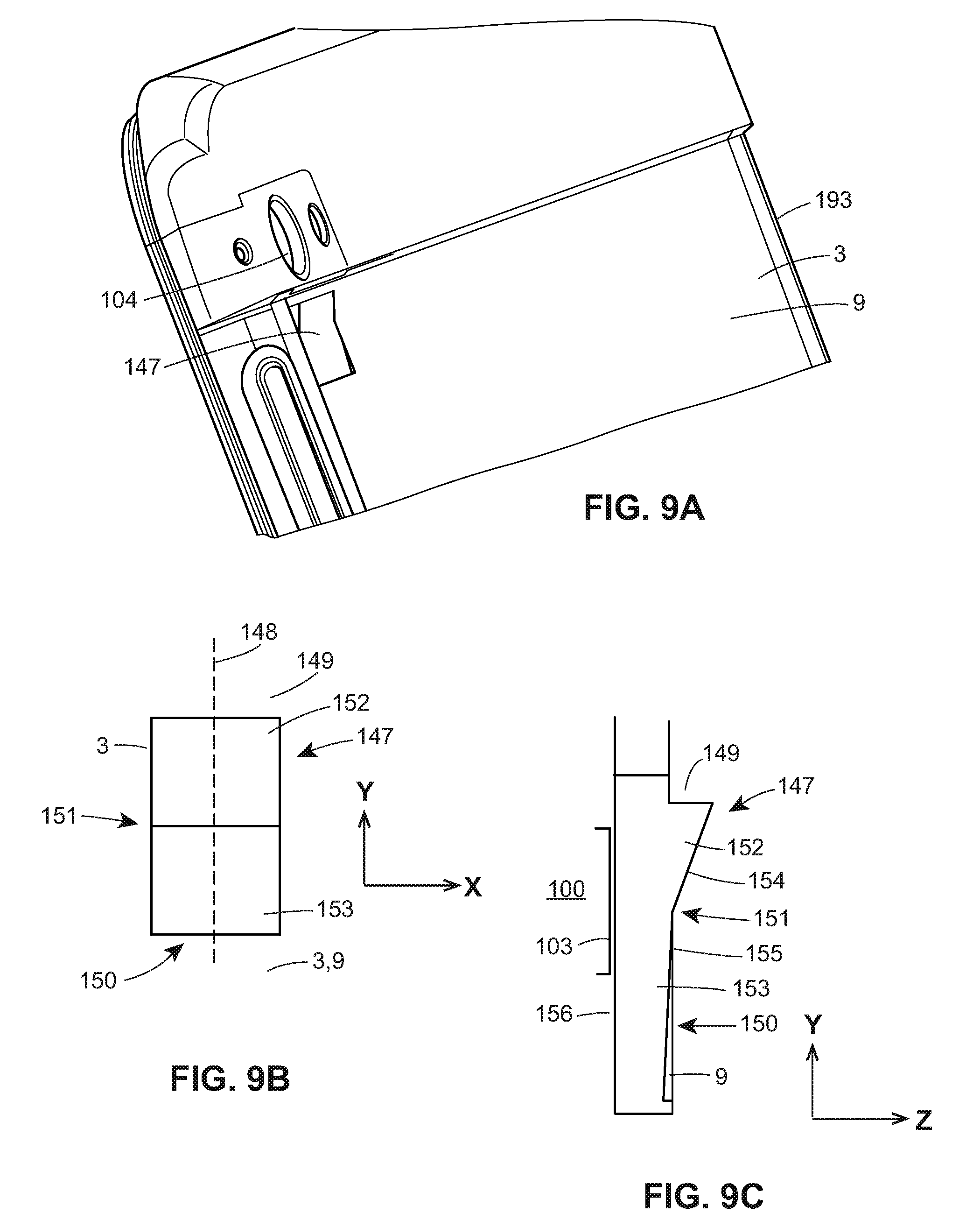
D00013

D00014
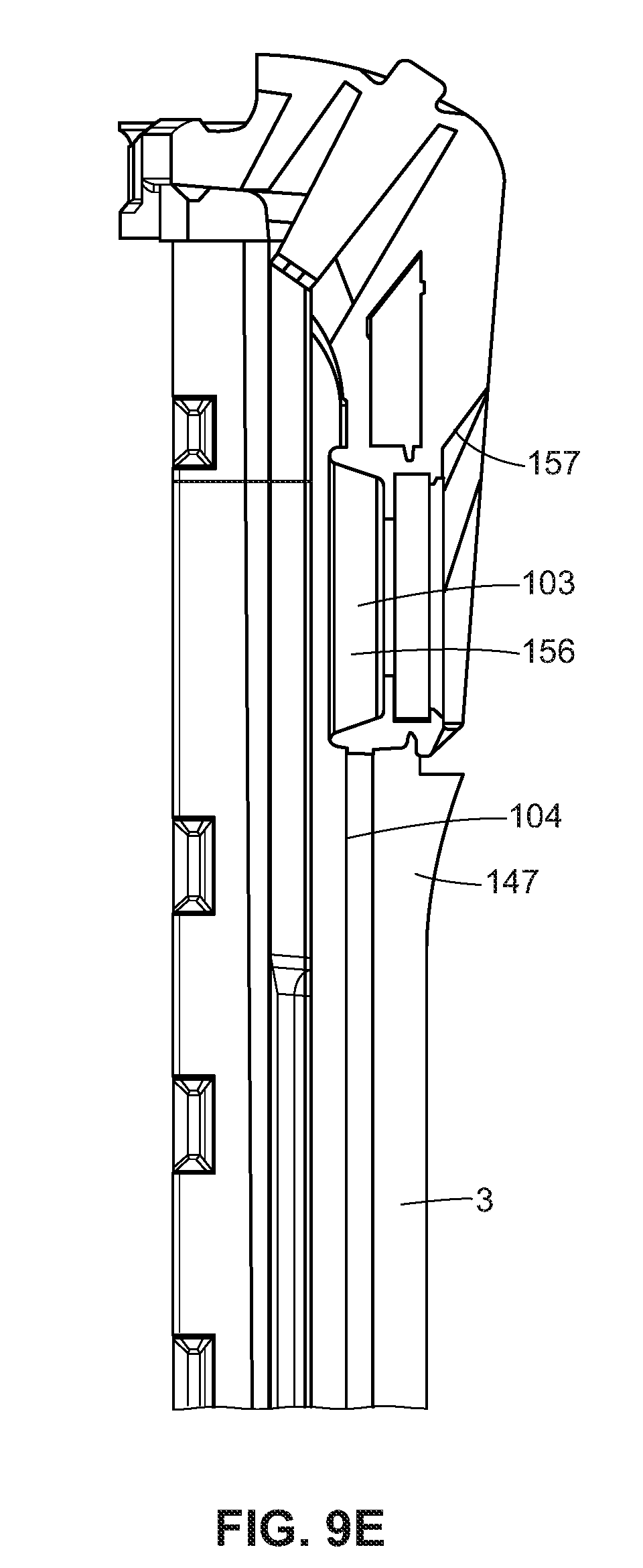
D00015

D00016

D00017

D00018

D00019

D00020

XML
uspto.report is an independent third-party trademark research tool that is not affiliated, endorsed, or sponsored by the United States Patent and Trademark Office (USPTO) or any other governmental organization. The information provided by uspto.report is based on publicly available data at the time of writing and is intended for informational purposes only.
While we strive to provide accurate and up-to-date information, we do not guarantee the accuracy, completeness, reliability, or suitability of the information displayed on this site. The use of this site is at your own risk. Any reliance you place on such information is therefore strictly at your own risk.
All official trademark data, including owner information, should be verified by visiting the official USPTO website at www.uspto.gov. This site is not intended to replace professional legal advice and should not be used as a substitute for consulting with a legal professional who is knowledgeable about trademark law.