System for landscape lighting customization and communication
Rivera , et al. J
U.S. patent number 10,178,747 [Application Number 15/873,113] was granted by the patent office on 2019-01-08 for system for landscape lighting customization and communication. This patent grant is currently assigned to Chien Luen Industries Co., Ltd., Inc.. The grantee listed for this patent is Chien Luen Industries Co., Ltd., Inc.. Invention is credited to Charles E. Bucher, Tien S. Lowe, Ronald R. Portorreal, Eliezer Rivera, Zachary Zauhar.


| United States Patent | 10,178,747 |
| Rivera , et al. | January 8, 2019 |
System for landscape lighting customization and communication
Abstract
Systems, devices and methods for providing a controller to be wired between a transformer and zones of landscape lights to provide power to and for turning on and off different landscape lights, creating and deleting landscape light zones based on a schedule loaded onto the controller by a wireless communication from a portable digital device, such as a smart phone having a landscape scheduling App thereon. Additional embodiments include wireless receivers in the landscape lights which allow for the portable digital device to remotely change colors of the landscape lights. Additional embodiments for controlling other accessories used in landscapes such as but not limited to sprinkler systems, speakers, and the like.
| Inventors: | Rivera; Eliezer (Plantation, FL), Portorreal; Ronald R. (Sunrise, FL), Zauhar; Zachary (Oakland Park, FL), Bucher; Charles E. (Tampa, FL), Lowe; Tien S. (Cooper City, FL) | ||||||||||
|---|---|---|---|---|---|---|---|---|---|---|---|
| Applicant: |
|
||||||||||
| Assignee: | Chien Luen Industries Co., Ltd.,
Inc. (Oakland Park, FL) |
||||||||||
| Family ID: | 64815792 | ||||||||||
| Appl. No.: | 15/873,113 | ||||||||||
| Filed: | January 17, 2018 |
Related U.S. Patent Documents
| Application Number | Filing Date | Patent Number | Issue Date | ||
|---|---|---|---|---|---|
| 62447659 | Jan 18, 2017 | ||||
| Current U.S. Class: | 1/1 |
| Current CPC Class: | F21S 10/02 (20130101); H05B 47/16 (20200101); H05B 47/155 (20200101); F21Y 2113/10 (20160801); H05B 45/20 (20200101); F21W 2131/109 (20130101) |
| Current International Class: | H05B 41/36 (20060101); F21S 10/02 (20060101); H05B 33/08 (20060101); H05B 37/02 (20060101); H05B 39/04 (20060101) |
References Cited [Referenced By]
U.S. Patent Documents
| 3194952 | July 1965 | Wells |
| 3777138 | December 1973 | Metzler |
| 5226721 | July 1993 | Stokes |
| 6249091 | June 2001 | Belliveau |
| 6331756 | December 2001 | Belliveau |
| 6357892 | March 2002 | Beadle |
| 6483470 | November 2002 | Hohnstein et al. |
| 6580361 | June 2003 | Bucher |
| 6782309 | August 2004 | Laflamme et al. |
| 6784357 | August 2004 | Wang |
| 6874905 | April 2005 | Beadle |
| 6984944 | January 2006 | Garrity |
| 7021787 | April 2006 | Kuelbs |
| 7083315 | August 2006 | Hansler |
| 7172307 | February 2007 | Izardel |
| 7192155 | March 2007 | Morrow et al. |
| 7204608 | April 2007 | Beeman et al. |
| 7309965 | December 2007 | Dowling et al. |
| 7387409 | June 2008 | Beadle |
| D574532 | August 2008 | Lee et al. |
| 7502034 | March 2009 | Chemel et al. |
| 7630776 | December 2009 | Harwood |
| 7659674 | February 2010 | Mueller et al. |
| 7817063 | October 2010 | Hawkins et al. |
| 7841734 | November 2010 | Wilcox |
| 8002428 | August 2011 | Boyer et al. |
| 8010319 | August 2011 | Walters et al. |
| 8042961 | October 2011 | Massara et al. |
| 8090453 | January 2012 | Harwood |
| D654611 | February 2012 | Chen |
| D663457 | July 2012 | Ho et al. |
| 8382347 | February 2013 | McCanless |
| 8534867 | September 2013 | Beadle |
| 8602585 | December 2013 | Lowe et al. |
| 8632234 | January 2014 | Lowe et al. |
| 8818530 | August 2014 | Netzel, Sr. et al. |
| 9004706 | April 2015 | Banfield |
| 9668053 | May 2017 | Rivera et al. |
| 2003/0127990 | July 2003 | Weng |
| 2004/0130909 | July 2004 | Mueller et al. |
| 2005/0002183 | January 2005 | Wardzala |
| 2005/0024857 | February 2005 | Vishwamitra |
| 2005/0253533 | November 2005 | Lys et al. |
| 2006/0039570 | February 2006 | Yeh |
| 2006/0126860 | June 2006 | Sievers et al. |
| 2006/0154598 | July 2006 | Rudland et al. |
| 2006/0203471 | September 2006 | Hodges et al. |
| 2007/0223723 | September 2007 | Haase |
| 2008/0074867 | March 2008 | Chen |
| 2009/0195063 | August 2009 | Joseph |
| 2009/0196016 | August 2009 | Massara et al. |
| 2009/0207607 | August 2009 | Haase et al. |
| 2010/0084985 | April 2010 | Woytowitz |
| 2010/0215201 | August 2010 | Kalomirakis et al. |
| 2011/0074266 | March 2011 | Sun |
| 2011/0175553 | July 2011 | Sampsell |
| 2012/0320572 | December 2012 | Fischer et al. |
| 2015/0102731 | April 2015 | Altamura et al. |
| 2015/0237700 | August 2015 | Woytowitz |
| 2015/0334811 | November 2015 | So |
Other References
|
Band I, Wikipedia, Aug. 15, 2012, retrieved from https://en.wikipedia.org/wiki/band_I, 3 pages. cited by applicant . FM Broadcasting in Japan, Wikipedia Aug. 15, 2012, retrieved from https://en.wikipedia.org/wiki/FM_broadcasting_in_Japan, 1 page. cited by applicant . America Starpower X2 Wireless Microphone System Operation Instructions, NADY Systems, Sep. 14, 2004, 4 pages. cited by applicant. |
Primary Examiner: A; Minh D
Attorney, Agent or Firm: Steinberger; Brian S. Law Offices of Brian S. Steinberger, P.A.
Parent Case Text
CROSS REFERENCE TO RELATED APPLICATION
This application claims the benefit of priority to U.S. Provisional Application Ser. No. 62/447,659 filed Jan. 18, 2017, the entire disclosure of which is incorporated herein by specific reference thereto.
Claims
We claim:
1. A communication system for controlling landscape lights, comprising: a transformer connected to a power source; a plurality of landscape lights mounted at different locations being powered through the transformer; and a computer controller wired between the transformer and the plurality of landscape lights, the controller for providing power to and for controlling operation of each of the landscape lights, the computer controller having a wireless receiver for receiving a schedule transmitted from a remote digital device, wherein the plurality of landscape lights includes a plurality of separate zones of landscape lights, each zone having at least one landscape light, and all of the zones are hardwired in series with the power source, and each zone is separately hardwired in parallel with the computer controller.
2. The communication system of claim 1, wherein the power source includes 120 volt power supply, and the transformer converts the 120 volt power supply to a 12 volt power.
3. The communication system of claim 1, wherein the schedule provides times for turning on and off the landscape lights.
4. The communication system of claim 1, wherein the schedule provides times for turning on and off the landscape lights.
5. The communication system of claim 4, wherein the schedule further provides scheduling times for adding a new zone having at least one landscape light to the plurality of zones and for deleting at least one of the plurality of zones.
6. The communication system of claim 1, wherein the controller includes: a wireless receiver antenna.
7. The communication system of claim 6, wherein the controller further includes: a real time clock for running the schedule.
8. The communication system of claim 7, wherein the controller further includes: a battery power supply to hold the settings in the real-time clock.
9. The communication system of claim 1, wherein the controller includes; a plurality of terminals for a plurality of zones.
10. The communication system of claim 9, wherein the plurality of terminals includes four terminals and the plurality of zones includes four zones.
11. The communication system of claim 1, wherein the remote digital device is selected from at least one of a smart phone, a tablet and a laptop computer.
12. The communication system of claim 11, wherein the remote digital device includes: an App downloaded onto the remote digital device for determining the schedule for operation of the landscape lights.
13. The communication system of claim 1, wherein the operation includes changing colors of each of the landscape lights.
14. The communication system of claim 13, wherein each of the landscape lights includes: a wireless receiver for receiving color changing instructions from the remote digital device for scheduling changes in the colors of each of the landscape lights.
15. The communication system of claim 14, wherein each of the landscape lights includes: light emitting diodes (LEDs).
16. A communication system for controlling landscape lights, comprising: a transformer in combination with a computer controller hardwired to a power supply, the transformer combined with the computer controller having a wireless receiver for receiving a schedule transmitted from a remote digital device; and a plurality of landscape lights mounted at different locations being powered through the combined transformer and controller, wherein the transformer combined with the controller is useful for controlling operation of each of the landscape lights, the plurality of landscape lights includes a plurality of zones, each zone having at least one landscape light, the combined transformer and controller controls activating and deactivating individual landscape lights and individual zones, and all of the zones are hardwired in series with the power source, and each zone is separately hardwired in parallel with the computer controller.
Description
FIELD OF INVENTION
This invention relates to landscape lighting, and in particular to systems, devices and methods for providing a controller to be wired between a transformer and zones of landscape lights to provide power to and for turning on and off different landscape lights, creating and deleting landscape light zones based on a schedule loaded onto the controller by a wireless communication from a portable digital device, such as a smart phone having a landscape scheduling App thereon, and another embodiment for providing landscape lights each with individual wireless receivers or power-line communication receivers so the portable digital device remotely changes colors of the landscape lights, and additional embodiments for controlling other accessories used in landscapes such as but not limited to sprinkler systems, speakers, and the like.
BACKGROUND AND PRIOR ART
Landscape lights are popular for lighting up residential and commercial pathways, driveways, yards, and the like. Typically, individual low voltage landscape lights are hard wired directly to a transformer which in turn is hardwired to a power source. Once installed the lights are generally controlled by the transformer having a photocell that turns the lights on at dusk and off after a user selectable amount of time or at dawn.
The prior art generally allows for only controlling one string of lights at a time, and not control multiple zones, where each zone can have a string of lights. The prior art generally does not allow for controlling individual lights or accessories connected to a string of lights. Accessories can include but are not limited to speakers, motion detectors, sprinklers, water fall pumps, and the like.
In the prior art, the user must run the powered cable from a 120 volt power supply to a transformer, which then is directly wired to a line of landscape lights. Here, a single switch is often used to power all lighting down the line. As such, there are problems with these prior art setups.
The single switch control is undesirable for the customer because the landscape lighting power source would need to be powered on at all times consuming energy and affecting the lifetime use of the power source.
Additionally, the operator would have to cut the landscape lighting cable for each light and then make two wiring connections in order for the switch to operate correctly.
Additionally, each zone of a string of landscape lights would also require separate switches to turn on and off the selected zone of landscape lights. As such, the more zones of the landscape lights, the more manual time is needed to operate and control the zones.
Thus, the need exists for solutions to the above problems with the prior art.
SUMMARY OF THE INVENTION
A primary objective of the present invention is to provide systems, devices and methods for providing a controller to be wired between a transformer and multiple zones of landscape lights to provide power to and for turning on and off different landscape lights, creating and deleting landscape light zones based on a schedule loaded onto the controller by a wireless communication from a portable digital device, such as a smart phone having a landscape scheduling App.
A secondary objective of the present invention is to provide systems, devices and methods for providing a controller to be wired between a transformer and multiple zones of landscape lights to provide power to and for turning on and off different landscape lights, creating and deleting landscape light zones based on a schedule loaded onto the controller by a wireless communication from a portable digital device, and for providing the landscape lights each with individual wireless receivers (or power-line communication receivers) so the portable digital device remotely changes colors of the landscape lights.
A third objective of the present invention is to provide systems, devices and methods for providing a controller to be wired between a transformer and landscape accessories, such as but not limited to speakers, sprinklers, and the like, for controlling those accessories, wherein a schedule in the controller is loaded from a wireless communication (or power-line communication receivers) from portable digital devices, such as but not limited to sprinkler systems, speakers, and the like.
A fourth objective of the present invention is to provide systems, devices and methods for providing a controller to be wired between a transformer and multiple zones of landscape lights. for universal or individual zone programming.
A fifth objective of the present invention is to provide systems, devices and methods for providing a controller to be wired between a transformer and multiple zones of landscape lights for universal or individual On/Off function capability.
A sixth objective of the present invention is to provide systems, devices and methods for providing a controller to be wired between a transformer and multiple zones of landscape lights for universal or individual timer function capability.
A communication system for controlling landscape lights, can include a transformer connected to a power source, a plurality of landscape lights mounted at different locations being powered through the transformer, and a controller wired between the transformer and the plurality of landscape lights, the controller for providing power to and for controlling operation of each of the landscape lights, the controller having a wireless receiver for receiving a schedule transmitted from a remote digital device.
The power source can include 120 volt power supply, and the transformer converts the 120 volt power supply to a 12 volt power.
The schedule can provide times for turning on and off the landscape lights.
The plurality of landscape lights can include a plurality of zones of landscape lights. Each zone can be separately hardwired to the controller.
The schedule can further provide scheduling times for adding a new zone having at least one landscape light to the plurality of zones and for deleting at least one of the plurality of zones.
The controller can include a wireless receiver antenna and a computer for storing the schedule. The controller can further include a real time clock for running the schedule. The controller can further include a battery power supply to hold the settings in the real-time clock.
The controller can include a plurality of terminals for a plurality of zones, such as four terminals and four zones.
The remote digital device can be selected from at least one of a smart phone, a tablet and a laptop computer. The remote digital device can include an App downloaded onto the remote digital device for determining the schedule for operation of the landscape lights.
The operation can include changing colors of each of the landscape lights.
Each of the landscape lights can include a wireless receiver for receiving color changing instructions from the remote digital device for scheduling changes in the colors of each of the landscape lights. Each of the landscape lights can include light emitting diodes (LEDs).
A communication system for controlling landscape lights, can include a transformer in combination with a controller hardwired to a power supply, the transformer combined with the controller having a wireless receiver for receiving a schedule transmitted from a remote digital device, and a plurality of landscape lights mounted at different locations being powered through the combined transformer and controller, wherein the transformer combined with the controller is useful for controlling operation of each of the landscape lights.
The plurality of landscape lights can include a plurality of zones.
The combined transformer and controller can control activating and deactivating individual landscape lights and individual zones.
Further objects and advantages of this invention will be apparent from the following detailed description of the presently preferred embodiments which are illustrated schematically in the accompanying drawings.
BRIEF DESCRIPTION OF THE FIGURES
The drawing figures depict different implementations in accord with the present concepts, by way of example only, not by way of limitations. In the figures, like reference numerals refer to the same or similar elements.
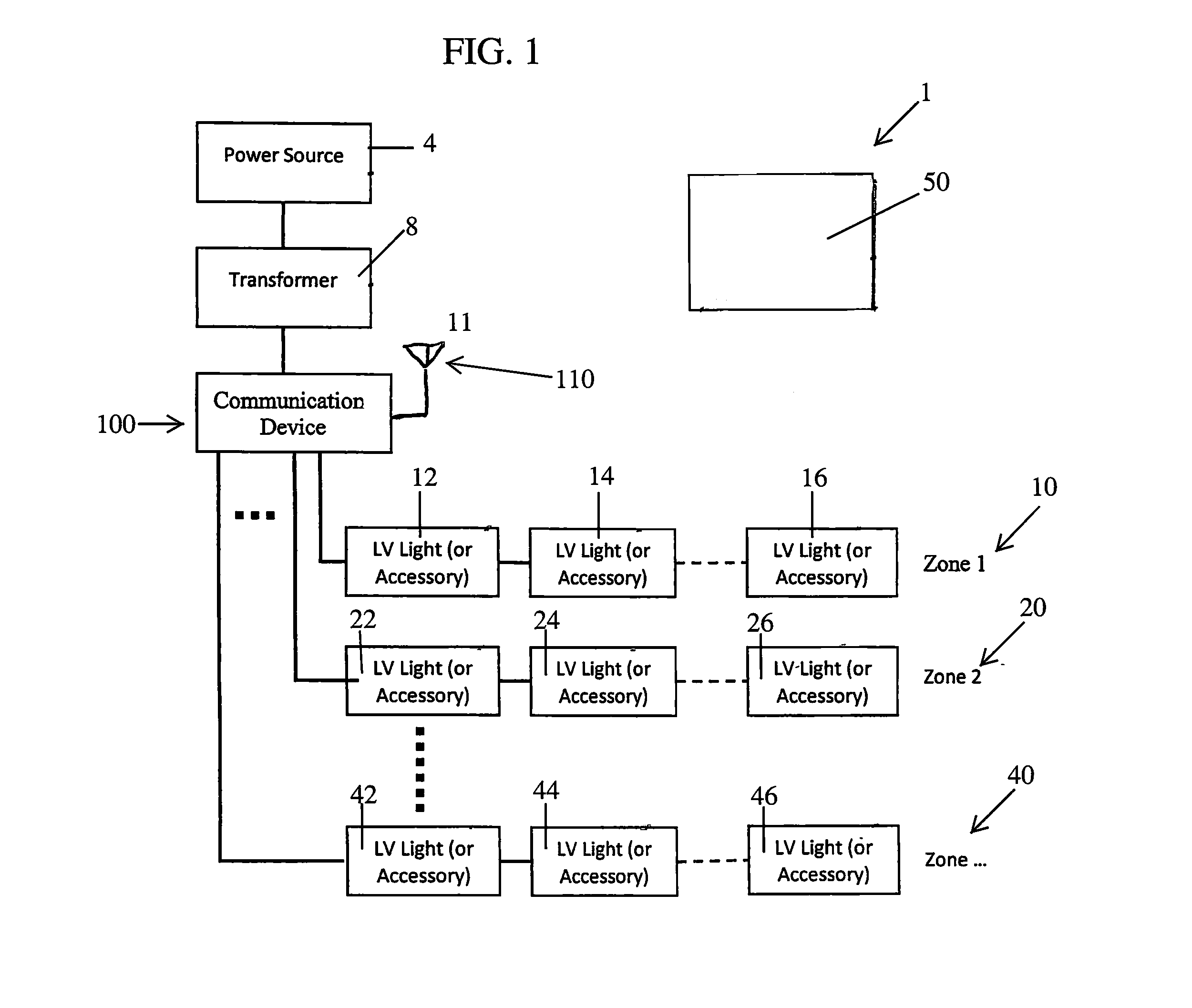
FIG. 1 is an overview of the landscape lighting system with communication device having a schedule loaded from a portable digital device.
FIG. 2 is another overview of the landscape lighting system of FIG. 1 with transformer hardwired to a communication device which is wired to different zones of landscape lights.
FIG. 3 is a block diagram of the circuit used in the communication device in FIGS. 1 and 2.
FIG. 4 is a flowchart of steps for setting up a schedule for the landscape lights.
FIGS. 5A, 5B, 5C and 5D are screen shots of pages from the portable digital device in FIGS. 1-3 running through the steps of setting up a schedule for the landscape lights and zones of FIGS. 1 and 2.
FIG. 6 is an overview of a second embodiment of the lighting system and communication device and portable digital device of FIG. 1 with each landscape light having wireless receivers that allow for the portable digital device to change colors of the landscape lights.
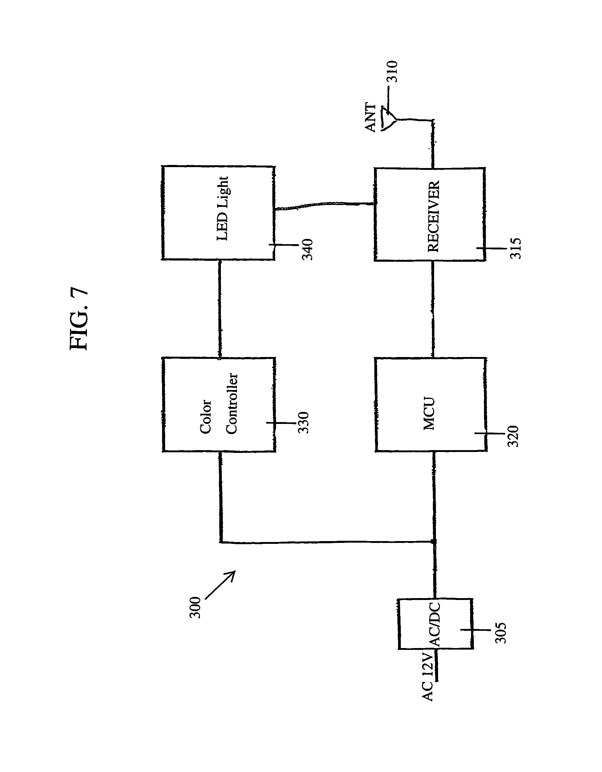
FIG. 7 is a block diagram of the circuit of a landscape light with a wireless receiver and color changeable LED lights used in FIG. 6.
DESCRIPTION OF THE PREFERRED EMBODIMENTS
Before explaining the disclosed embodiments of the present invention in detail it is to be understood that the invention is not limited in its applications to the details of the particular arrangements shown since the invention is capable of other embodiments. Also, the terminology used herein is for the purpose of description and not of limitation.
In the Summary above and in the Detailed Description of Preferred Embodiments and in the accompanying drawings, reference is made to particular features (including method steps) of the invention. It is to be understood that the disclosure of the invention in this specification does not include all possible combinations of such particular features. For example, where a particular feature is disclosed in the context of a particular aspect or embodiment of the invention, that feature can also be used, to the extent possible, in combination with and/or in the context of other particular aspects and embodiments of the invention, and in the invention generally.
In this section, some embodiments of the invention will be described more fully with reference to the accompanying drawings, in which preferred embodiments of the invention are shown. This invention may, however, be embodied in many different forms and should not be construed as limited to the embodiments set forth herein. Rather, these embodiments are provided so that this disclosure will be thorough and complete, and will convey the scope of the invention to those skilled in the art. Like numbers refer to like elements throughout, and prime notation is used to indicate similar elements in alternative embodiments.
A list of components will now be described. 1 Landscape lighting system for scheduling lights 4 power source 8 transformer 10 zone 1 landscape lights 12 landscape light 14 landscape light 16 landscape light 20 zone 2 landscape lights 22 landscape light 24 landscape light 26 landscape light 30 zone 3 landscape lights 32 landscape light 34 landscape light 36 landscape light 40 zone 4 landscape lights 42 landscape light 44 landscape light 46 landscape light 50 remote digital device (smart phone, tablet computer, laptop computer . . . ) 100 smart controller/communication device 110 antenna 115 wireless receiver 120 micro controller unit 105 per illustration in FIG. 3 power supply 140 realtime clock 150 battery 160 terminal one 170 terminal two 180 terminal three 190 terminal four 200 Second embodiment lighting system for changing colors of lights 210 zone 1 landscape lights 212 landscape light 214 landscape light 216 landscape light 220 zone 2 landscape lights 222 landscape light 224 landscape light 226 landscape light 240 zone 4 landscape lights 242 landscape light 244 landscape light 246 landscape light 300 landscape light with wireless receiver for changing light colors 305/105 power supply 310 antenna 315 receiver 320 micro controller 330 color controller 340 Light, i.e. LED (light emitting diode).
FIG. 1 is an overview of the landscape lighting system 1 with communication device (smart controller) 100 having a schedule loaded from a portable digital device 50. FIG. 2 is another overview of the landscape lighting system 1 of FIG. 1 with transformer 8 hardwired to a communication device (smart controller) which is wired to different zones 10, 20, 30, 40 of landscape lights 12-46. FIG. 3 is a circuit diagram that can be used in the communication device 100 in FIGS. 1 and 2.
Referring to FIGS. 1-3, the landscape lighting system 1 can receive power such as 120 volt power from a power source in a commercial building or residential building and the like. A low voltage transformer 8 can provide 12 volts by wire connection to the smart controller (communication device 100, which provides power by being hardwired to zones 10, 20, 30, and 40. Each zone having at least one, and preferably more than one landscape light(s) in series in each zone.
For this embodiment, the power source, transformer and a string of landscape lights in series can use low voltage landscape/pathway lights shown and described in U.S. Pat. No. 8,602,585 to Lowe et al. and U.S. Pat. No. 9,668,053 to Rivera et al., each of which is assigned to the same assignee as the subject patent application, and each of which are incorporated by reference in their entirety.
The novel communication device (smart controller) 100 is preferably hardwired between the transformer and each of the zones 10, 20, 30, 40 of landscape lights 12-46. The communication device 100 can include a MCU (micro controller) 120 that can have a schedule of landscape light zones 10, 20, 30, 40 and landscape lights 12-46 programmed into the MCU 120 by a remote digital device 50 through receiving antenna 110 through an RF wireless module 115 for external communication.
The smart controller (communicator) 100 can be powered by 12 volt AC from transformer 8, and a power supply circuit 105 can provide power to the MCU 120, RF module 115 and RTC (real time clock) 140. The RTC 140 can be a real time clock for scheduling the times of the lights 12-46 and zones 10-40. A battery 150, such as a 12 volt battery and the like, can be used to hold and maintain the settings in the RTC 140. The battery 150 can run the real time clock during power failures, and can have a long battery lifespan up to for example, three or more years.
In a preferred embodiment the smart controller (communicator device) 100 can have four terminals 160, 170, 180, 190 each for controller respective zones 10, 20, 30, 40 of landscape lights. A zone can have at least one landscape light, and a zone can have a plurality of landscape lights. For example, zone 1 (10) can have a plurality of landscape lights 12, 14, 16. Zone 2 (20) can have a plurality of landscape lights 22, 24, 26. Zone 3 (30) can have a plurality of landscape lights 32, 34, 36. Zone 4 (40) can have a plurality of landscape lights 42, 44, 46. Although each zone is shown and described as having four lights, each zone can have less than or more than four lights.
The portable digital device 50 that can be used to send a schedule by wireless transmission to the smart controller (communication device) 100 can be selected from at least one of a smart phone, a tablet computer and a laptop computer, and the like. The wireless transmission can be through Bluetooth, WIFI, Zigbee, RF (radio frequency) and the like.
Referring to FIG. 3, the antenna 110 can also be used to transmit data through a wireless medium (such as but not limited to Bluetooth, and the like) to the portable digital device 50. The data can include but is not limited to data described below, such as but not limited to wattage information, power saving modes, and the like.
While the embodiment in FIGS. 1-3 show the transformer 8 hardwired to the communication device (smart controller), a transformer can be combined with the communication device (smart controller) as a single combined unit.
FIG. 4 is a flowchart of steps for setting up a schedule to be programmed into the MCU 120 of the smart controller (communication device) 100 for the landscape lights 12-46.
The portable digital device 50 can have an App downloaded thereon from a website.
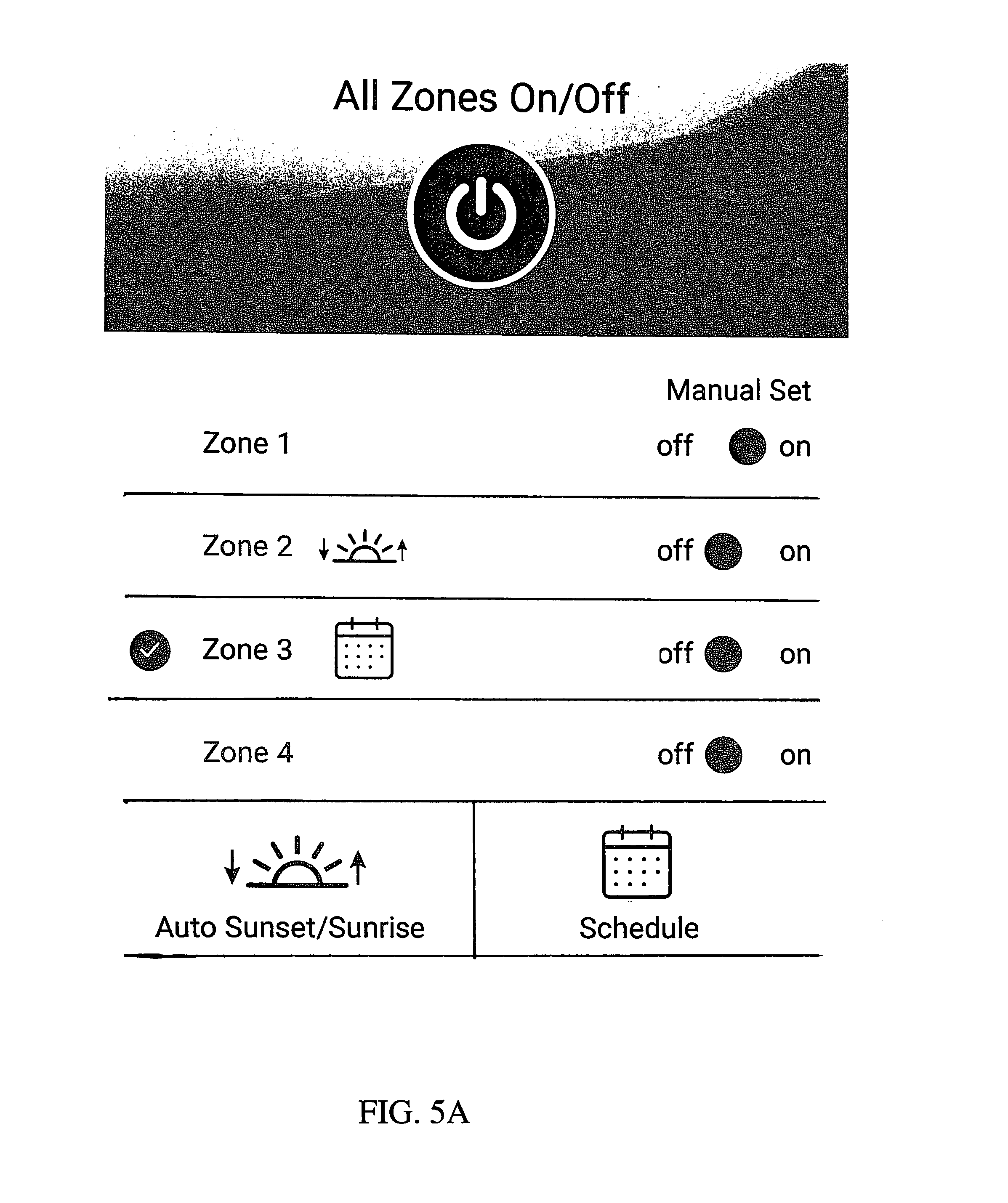
FIGS. 5A, 5B, 5C and 5D are screen shots of pages from the portable digital device in FIGS. 1-3 running through the steps of setting up a schedule for the landscape lights and zones of FIGS. 1 and 2.
FIG. 5A shows a main page that shows the following:
1. Put zones into manual on/off
2. Turn all zones on/off
3. Select multiple zones
4. Add zone(s)
5. Set sunset/sunrise mode
6. Enter scheduling.
The main page in FIG. 5A can also:
1. Put zones into manual on/off
2. Select multiple zones
3. Set View if in sunset/sunrise mode
4. View if in schedule
FIG. 5B shows a schedule page that includes the following:
1. Select days of the week
2. Set Auto on
3. Set Auto off
4. Set exact on time
5. Set exact off time
6. Clear schedules
The schedule page can also display:
1 Select days of the week
2 Sunset sunrise time
3 Zone name and number
Referring to FIGS. 5A-5B, icons (having sunrise/sunset design and schedule design) and all other features can be push button or slide button activated. Check symbol designs can be push button activated for activating each of the zones.
FIG. 5C shows a screen shot of a setting for the Sunrise Auto off. An On/off time display can be selected (showing Sunset at 7:34 pm and Sunrise 6:45 am). The Auto slider can be set to OFF. The time picker screen can be slid to a selected time (showing for example 7 05 am).
Referring to the schedule page, the user can:
1. Set Auto off (sunrise)
2. Set hrs off (select hrs 1, 2, 3, 4, 5, 6)
3. Set exact off time
4. Clear schedules
FIG. 5D shows a screen shot for On Time.
Referring to the schedule page, the user can:
1. Set Auto on (sunset)
2. Set exact on time
3. Clear schedules
The Sunset to Sunrise scheduling can be based off of zip code (universal or individual)
FIG. 6 is an overview of a second embodiment of the lighting system 200 and communication device 100 and portable digital device 50 of FIG. 1 for zone 1 (210), zone 2 (220) and zone ## (240). Each landscape lights 212, 214, 216, 222, 224, 226, 242, 244, 246 having wireless receivers that allow for the portable digital device 50 to change colors of each landscape light(s) 212-246.
FIG. 7 is a circuit diagram 300 of an individual landscape light (212-246) with a wireless receiver 310 and color changeable LED light 340) used in FIG. 6.
Referring to FIGS. 1-3 and 6-7, the system 200 can operate similar to the previous embodiment with power supply 305(105) with the addition of having landscape lights 212-246 each with antennas 310 and micro controller unit 320 with color controller 330 which control and are able to change the colors of individual lights 340, such as LED (light emitting diodes) 360 and the like.
The individual landscape lights can include an antenna and MCU such as those shown and described in U.S. Pat. No. 9,668,053 to Rivera et al, which is assigned to the same assignee as the subject patent application and incorporated by reference in its' entirety. Color changing LEDs (light emitting diodes) 340 and color controller 330 can include those shown and described in U.S. Pat. No. 6,782,309 to Laflamme et al, which is incorporated by reference, as well as those shown and described in U.S. Patent Application Publications 2005/0253533 to Lys et al. and 2015/0102731 to Altamura et al. which are both incorporated by reference in their entirety.
Similar to the smart controller/communication device 100, the antenna 310 can also be used to transmit data through a wireless medium (such as but not limited to Bluetooth, and the like) to either or both the portable digital device 50 and the smart controller/communication device. The data can include but is not limited to data described below, such as but not limited to wattage information, power saving modes, and the like.
The portable digital device 50 can have an App downloaded from a website that allows for controlling colors or each landscape light, and/or for controlling colors of each zone, as selected.
Similar to the previous embodiment, power can be supplied through transformer 8 which is wired to the smart controller (communication device) 110 and through each terminal 160, 170, 180, 190, that are each wire connected in series to respective string of lights 212-216, 222, 226, 242-246.
The power passing into each zone 210, 220, 230 can be supplied by the transformer power 8 that is hardwired to the power input 305 and MCU 320 and color controller 330 of LED Light 340 of each landscape light 212-246.
A preferred embodiment can communicate with the antenna 310 on each light through wireless frequency communications from the portable digital device 50. Alternatively, communication can run through the power lines as modulated data using a power-line communication protocol.
Data that can be communicated between each landscape light can include but not be limited to Real Time Wattage Usage.
Real Time Wattage Usage can be described when the installer can visually understand an estimated energy consumption of each zone. This is important to know since the zones cannot exceed 100 w each zone. It also can send feedback if after the system is configured, and the wattage consumption changes, it would be an indication that a device may not be on when it is supposed to be. a. Detection of current wattage usage from items on a low voltage cable b. Sending or receiving of this real-time wattage data to designate a sub task Sub Task can include but not limited to Real time wattage to be transferred back to master communications device, such as a smart phone. i. SMS (or notification depicting usage ii. A light or screen revealing usage is under or exceeding a certain wattage. iii. "Smart sense" where the wattage is monitored to determine an average wattage consumption. If the wattage drops below the average established, the owner is notified to check the system. A light or lights can have gone out.
The invention can use photo cell function Photo Cell Function where a photo cell triggers an event based on the current generated by the energy picked up from light coming into the photo cell. If the current generated falls below a programmed value, the system is triggered. If the current goes above the programmed value, the system is triggered.
The invention can be customized to use for designated zones
User based feedback that can be utilized to control settings in the device.
User feedback can enable the sub action to take place. Examples of sub actions can include but not limited to, something being turned on or off, dimmed, color changed
User feedback can include: a. Hand waving (Motion Activation)--using passive infrared sensor or PIR the system can pick up movement to trigger a function b. Touch activation--Using sensors, such as a capacitive sensor, the system can trigger a function. c. Audible interaction (Voice launching based on specific commands)
Weather based settings can be incorporated into the invention. a. Weather data can be gathered from a communications device and initiate a set of sub actions i. Example 1: It is 5 pm and a communications device or system collects information that it is predicted to rain that evening at 7 pm. At 5 pm the lights can start repeatedly diming to notify others that rainfall is coming. ii. Example 2: It is 5 pm and a communications device or system collects information that it is predicted to rain that evening at 7 pm. At 5 pm the lights can start repeatedly diming and get faster to notify others that rainfall is coming and is close by. iii. Example 3: It is 5 pm and a communications device or system collects information that it is predicted to rain that evening at 7 pm. At 5 pm the lights can change color to notify others that lightning is coming. iv. System can create noise that resembles lighting or rain fall to notify users of incoming weather conditions
Holiday Based settings can be incorporated into the invention. Based on the time or date a holiday based setting can be implemented can be gathered from a communications device and initiate a set of sub actions: i. Example 1: It is 1 week before Halloween and a communications device or system collects information that based on a date or time certain light color themes, for this case an orange and purple light color theme should be started for a certain period of time. ii. Example 2: It is 2 weeks before Christmas and a communications device or system collects information that based on a date or time certain light color themes, for this case a Green and Red light color theme should be started for a certain period of time. iii. Example 3: It is 3 weeks before Christmas and a communications device or system collects information that based on a date or time certain projection such as a snow flake or other Christmas themed lenses can be initiated and projected on a home. iv. Example 4: It is 2 days before St. Patrick's day and a communications device or system collects information that based on a date or time certain projection such as a 4 leaf clover or other Saint Patrick themed lenses can be initiated and projected on a home.
The system can play holiday music provided by user that is stored on device, such as but not limited to: 1. Halloween music 2. Christmas music 3. User Created Content
Power saving based settings can be incorporated into the invention:
A system that can detect a power saving mode that alter performance based on savings desired. An example would be a "power saving mode" that can be a setting on a smartphone and once set would send a signal to a listening device and initiate power saving activity to select devices.
Energy Conservation mode where the user gives the system a set amount of power it can consume and require it to turn off after that power requirement has been met
Power Outage setting to turn on/off:
Communication enabling device to turn on/off Diming, which can be Fully Customizable with Low/Medium/High settings.
The invention can enable customization of zones for different portions of a yard. A Set timer or let dawn to dusk program can adjust it automatically based on Geolocation of an object, such as a wireless device, mobile phone, or internet connected device.
The invention can incorporate a feature that enables a projector to display different color patterns or images via feedback from a connections device Security settings based on feedback, such as: a. Example 1: would be if a button is pressed inside and designated lights can turn on to ward off potential risks. b. Example 2: Would be if a sensor or other alarm is triggered than different colored lights can be lite in certain areas of a home. Multiple motion sensors go off and a spotlight turns on. Multiple motion sensors go off and a red light turns on.
Security settings based on motion can be incorporated where for example, a person walking or moving in a yard, pathway, driveway, or area within range of the motion sensor:
a. Motion sensors to turn on designated lights.
b. User based setting that enables the playing of audio or tone
Setting to control other communications devices such as a sprinkler system, ceiling fan, television, pool lights, and the like.
The invention can include a method incorporating wireless or in-line landscape lighting accessories to landscape lighting systems. Accessories such as motion detectors, security cameras, and photo sensors can activate landscape lighting systems by sending a wired or wireless signal to the power source of the landscape lighting system.
The accessories can operate on a rechargeable battery when the landscape lighting system was powered off. When the landscape lighting system is powered, the battery would recharge using the current provided by the landscape lighting power source.
The advantage of the wireless connectivity would allow the landscape lighting system to be turned off in a hibernation mode while waiting for the accessory to signal the landscape lighting power source to turn on.
In prior art, the user must run the powered cable to the accessory first and then the accessory would act as a switch to power all lighting down the line. This is undesirable for the customer because the landscape lighting power source would need to be powered on at all times consuming energy and affecting the lifetime use of the power source. Also, the operator would have to cut the landscape lighting cable at the prior art accessory and then make two wiring connections in order for the switch to operate correctly. In the current innovation, the accessory can be placed in any location along the powered cable that is in radio frequency range of the landscape lighting power source.
Although the invention is described for use with landscape lights, the invention can be used with other accessories. Accessories can include but are not limited to: a. Low Voltage Lights b. Color Changing Lights c. Speaker Systems d. Weather Based Sensor e. Hub f. Ceiling fans g. Pool lights h. Remote control i. Solar lights j. Solar system k. Sprinkler system l. Smartphone m. Smart device n. Security PIR Sensors o. Security system p. IOT (internet of things) device, such as a remote device connected to internet through a hub or router. q. Pond/fountain Pumps
While the embodiments refer to four zones, the invention can work with as few as two zones, as well as more than four zones, such as but not limited to up to eight zones, and more.
Although FIG. 6 shows a wireless communication, the system can alternatively use power line communications protocol where data is modulated with the power supply connection lines.
While a portable digital device 50 is shown and described, the invention can include a desktop computer, and the like to provide the wireless transmission to the smart controller (communication device) 100.
The term "approximately" can be +/-10% of the amount referenced. Additionally, preferred amounts and ranges can include the amounts and ranges referenced without the prefix of being approximately.
While the invention has been described, disclosed, illustrated and shown in various terms of certain embodiments or modifications which it has presumed in practice, the scope of the invention is not intended to be, nor should it be deemed to be, limited thereby and such other modifications or embodiments as may be suggested by the teachings herein are particularly reserved especially as they fall within the breadth and scope of the claims here appended.
* * * * *
References
D00000
D00001
D00002
D00003
D00004
D00005
D00006
D00007
D00008
D00009
D00010
XML
uspto.report is an independent third-party trademark research tool that is not affiliated, endorsed, or sponsored by the United States Patent and Trademark Office (USPTO) or any other governmental organization. The information provided by uspto.report is based on publicly available data at the time of writing and is intended for informational purposes only.
While we strive to provide accurate and up-to-date information, we do not guarantee the accuracy, completeness, reliability, or suitability of the information displayed on this site. The use of this site is at your own risk. Any reliance you place on such information is therefore strictly at your own risk.
All official trademark data, including owner information, should be verified by visiting the official USPTO website at www.uspto.gov. This site is not intended to replace professional legal advice and should not be used as a substitute for consulting with a legal professional who is knowledgeable about trademark law.