Registration Of Local Content Between First And Second Augmented Reality Viewers
MCCALL; Marc Alan
U.S. patent application number 17/429100 was filed with the patent office on 2022-04-28 for registration of local content between first and second augmented reality viewers. This patent application is currently assigned to Magic Leap, Inc.. The applicant listed for this patent is Magic Leap, Inc.. Invention is credited to Marc Alan MCCALL.
| Application Number | 20220130116 17/429100 |
| Document ID | / |
| Family ID | |
| Filed Date | 2022-04-28 |


| United States Patent Application | 20220130116 |
| Kind Code | A1 |
| MCCALL; Marc Alan | April 28, 2022 |
REGISTRATION OF LOCAL CONTENT BETWEEN FIRST AND SECOND AUGMENTED REALITY VIEWERS
Abstract
A method of viewing image data of local content is disclosed. An augmented reality view is created by storing a first device coordinate frame (DCF), moving a first registration marker to select a first feature point (FP1) and a second feature point (FP2) on at least one real-word object viewable by the user through a display. A uniform coordinate system (UCS) alignment module stores locations of the registration marker when selecting the FP1 and the FP2, determines a user coordinate frame (UCF) based on the locations of the first registration marker when selecting the FP1 and the FP2, transforms the DCF to the UCF and displays image data of local content received on a first data source with a projector through the display to the user based on the transformation from the first DCF to the first UCF.
| Inventors: | MCCALL; Marc Alan; (Plantation, FL) | ||||||||||
| Applicant: |
|
||||||||||
|---|---|---|---|---|---|---|---|---|---|---|---|
| Assignee: | Magic Leap, Inc. Plantation FL |
||||||||||
| Appl. No.: | 17/429100 | ||||||||||
| Filed: | February 26, 2020 | ||||||||||
| PCT Filed: | February 26, 2020 | ||||||||||
| PCT NO: | PCT/US2020/019871 | ||||||||||
| 371 Date: | August 6, 2021 |
Related U.S. Patent Documents
| Application Number | Filing Date | Patent Number | ||
|---|---|---|---|---|
| 62817318 | Mar 12, 2019 | |||
| 62836417 | Apr 19, 2019 | |||
| International Class: | G06T 19/00 20060101 G06T019/00; G06V 20/20 20060101 G06V020/20; G06T 7/70 20060101 G06T007/70; G06F 3/01 20060101 G06F003/01; G02B 27/01 20060101 G02B027/01 |
Claims
1. A viewing system comprising: a first augmented reality viewer that includes: a first display that permits a first user to see real world objects; a first data source to hold image data of local content; a first projector to display the image data of local content through the first display to the first user while the first user views the real world objects; a first processor; a first computer-readable medium connected to the first processor; and a first set of vision data and algorithms on the first computer-readable medium and executable by the processor, wherein the first set of vision data and algorithms comprises: a first device coordinate frame (DCF); a first registration marker operable by the first user to select a first feature point (FP1) and a second feature point (FP2) on at least one of the real word objects; and a first uniform coordinate system (UCS) alignment module including: a first feature point storing module that stores locations of the first registration marker when selecting the FP1 and the FP2; a first user coordinate frame calculator determining a first user coordinate frame (UCF) based on the locations of the first registration marker when selecting the FP1 and the FP2; a first transformer to transform the first DCF to the first UCF; and a first render engine that displays the image data of local content on the first data source based on the transformation from the first DCF to the first UCF.
2. The viewing system of claim 1, further comprising: a second augmented reality viewer that includes: a second display that permits a second user to see real world objects; a second data source to hold image data of local content; a second projector to display the image data of local content through the second display to the second user while the second user views the real world objects; and a second processor; a second computer-readable medium connected to the second processor; a second set of vision data and algorithms on the second computer-readable medium and executable by the processor, including: a second device coordinate frame (DCF); a second registration marker operable by the second user to select the FP1 and the FP2 on said at least one of the real word objects; a second uniform coordinate system (UCS) alignment module having: a second feature point storing module that stores locations of the second registration marker when selecting the FP1 and the FP2; a second user coordinate frame calculator determining a second user coordinate frame (UCF) based on the locations of the second registration marker when selecting the FP1 and the FP2; a second transformer to transform the second DCF to the second UCF; and a second render engine that displays the image data of local content on the second data source based on the transformation from the second DCF to the second UCF.
3. The viewing system of claim 2, wherein the first augmented reality viewer includes: a first head-mountable frame that is wearable on a head of the first user; and a first six degree of freedom (6 dof) controller that is movable relative to the first head-mountable frame by the first user to select the FP1 and FP2, wherein the first set of vision data and algorithms includes: a first feature point location calculator that determines the locations of the first registration marker when selecting the FP1 and FP2 by determining locations of the first 6 dof controller relative to the first head-mountable frame when selecting the FP1 and FP2; and a first feature storing module that stores the locations of the 6 dof controller in the first DCF.
4. The viewing system of claim 3, wherein the second augmented reality viewer includes: a second head-mountable frame that is wearable on a head of the second user; and a second six degree of freedom (6 dof) controller that is movable relative to the second head-mountable frame by the second user to select the FP1 and FP2, wherein the second set of vision data and algorithms includes: a second feature point location calculator that determines the locations of the second registration marker when selecting the FP1 and FP2 by determining locations of the 6 dof controller relative to the second head-mountable frame when selecting the FP1 and FP2; and a second feature storing module that stores the locations of the second 6 dof controller in the second DCF.
5. The viewing system of claim 1, wherein the first viewing device further includes: a first DCF determining routine executable by the first processor to calculate the first DCF that changes upon movement of the first head-mountable frame; and a first DCF storing instruction executable by the first processor to store the first DCF on the first computer-readable medium.
6. The viewing system of claim 5, wherein the first viewing device further includes: a first real object detection device that detects positioning of at least one real object; a first world object identification routine executable by the first processor to identify positioning of at least one point on a surface of the real object; a first world frame determining routine executable by the first processor to calculate a first world coordinate frame based on the at least one point; and a first world frame storing instruction executable by the first processor to store the world coordinate frame on the computer-readable medium, wherein the DCF determining routine determines the DCF relative to the world frame.
7. The viewing system of claim 6, wherein the first real object detection device is a camera.
8. The viewing system of claim 6, wherein the first real object detection device detects positioning of a plurality of real objects.
9. The viewing system of claim 6, wherein the first world object identification routine identifies positioning of a plurality of points on a surface of the real object.
10. The viewing system of claim 9, wherein the first world frame determining routine calculates the first world coordinate frame based on the plurality of points.
11. The viewing system of claim 5, wherein the first viewing device further includes: a first inertial measurement unit (IMU) secured to the first head-mountable frame, the first IMU including a first gravitational sensor that detects a first direction of gravitational force relative to the first head-mountable frame and the DCF determining routine calculates the DCF frame based on the first direction of gravitational force.
12. The viewing system of claim 11, wherein the first IMU includes at least one of a first accelerometers and a first gyroscope.
13. A method of viewing image data of local content comprising: creating a first augmented reality view including: storing a first device coordinate frame (DCF) on a first computer-readable medium; moving, by a first user, a first registration marker to select a first feature point (FP1) and a second feature point (FP2) on at least one real word object viewable by the first user through a first display; executing a first uniform coordinate system (UCS) alignment module by: storing locations of the first registration marker when selecting the FP1 and the FP2; determining a first user coordinate frame (UCF) based on the locations of the first registration marker when selecting the FP1 and the FP2; transforming the first DCF to the first UCF; and displaying image data of local content received on a first data source with first projector through the first display to the first user, while the first user views real world objects, based on the transformation from the first DCF to the first UCF.
14. The method of claim 13, further comprising: creating a second augmented reality view including: storing a second device coordinate frame (DCF) on a second computer-readable medium; moving, by the second user, a second registration marker to select a first feature point (FP1) and a second feature point (FP2) on at least one the real word object viewable by the user through a second display; executing a second uniform coordinate system (UCS) alignment module by: storing locations of the second registration marker when selecting the FP1 and the FP2; determining a second user coordinate frame (UCF) based on the locations of the second registration marker when selecting the FP1 and the FP2; transforming the second DCF to the second UCF; and displaying image data of local content received on a second data source with second projector through the second display to the second user, while the second user views the real world objects, based on the transformation from the second DCF to the second UCF.
15. The method of claim 16, further comprising: wearing, on a head of the first user, a first head-mountable frame; and moving, by the first user, a first six degree of freedom (6 dof) controller relative to the first head-mountable frame to select the FP1 and FP2; executing a first feature point location calculator to determine the locations of the first registration marker when selecting the FP1 and FP2 by determining locations of the first 6 dof controller relative to the first head-mountable frame when selecting the FP1 and FP2; and executing a first feature storing module to store the locations of the 6 dof controller in the first DCF.
16. The method of claim 15, further comprising: wearing, on a head of the second user, a second head-mountable frame; and moving, by the second user, a second six degree of freedom (6 dof) controller relative to the second head-mountable frame to select the FP1 and FP2; executing a second feature point location calculator to determine the locations of the second registration marker when selecting the FP1 and FP2 by determining locations of the second 6 dof controller relative to the second head-mountable frame when selecting the FP1 and FP2; and executing a second feature storing module to store the locations of the 6 dof controller in the second DCF.
17. The method of claim 13, further comprising: executing, with a first processor, a first DCF determining routine to calculate the first DCF that changes upon movement of the first head-mountable frame; and executing, with the first processor, a first DCF storing instruction executable by the first processor to store the first DCF on the first computer-readable medium.
18. The method of claim 17, further comprising: detecting, with a first real object detection device, positioning of at least one real object; identifying, with a first world object identification routine executable by the first processor, positioning of at least one point on a surface of the real object; calculating, with a first world object identification routine executable by the first processor, a first world coordinate frame based on the at least one point; and storing, with a first world frame storing instruction executable by the first processor, the world coordinate frame on the computer-readable medium, wherein the DCF determining routine determines the DCF relative to the world frame.
19. The method of claim 18, wherein the first real object detection device is a camera.
20. The method of claim 18, wherein the first real object detection device detects positioning of a plurality of real objects.
Description
CROSS-REFERENCE TO RELATED APPLICATIONS
[0001] This application claims priority from U.S. Provisional Patent Application No. 62/817,318, filed on Mar. 12, 2019 and U.S. Provisional Patent Application No. 62/836,417, filed on Apr. 19, 2019, each of which is incorporated herein by reference in their entirety.
BACKGROUND OF THE INVENTION
1). Field of the Invention
[0002] This invention relates to a viewing system having first and second augmented reality viewers and registration of local content for viewing by the viewers.
2). Discussion of Related Art
[0003] Modern computing and display technology has facilitated the development of user interaction systems that include "augmented reality" viewers. Such a viewer usually has a head unit with a head-mountable frame that a user can secure to their head and frequently includes two waveguides, one in front of each eye of the user. The waveguides are transparent so that ambient light from real-world objects can transmit through the waveguides and the user can see the real-world objects. Each waveguide also serves to transmit projected light from a projector to a respective eye of the user. The projected light forms an image on the retina of the eye. The retina of the eye thus receives the ambient light and the projected light. The user simultaneously sees real-world objects and one or more virtual objects that are created by the projected light.
[0004] In this manner, a user can see a rendering of local content within the real world. Two users within a room will each have their own local content displayed to them. It may sometimes be required that two users see the same local content in the same location. Two users may, for example, wish to see the same local content in the same location when they collaborate over a project, play a game, join in the watching of a sports event, etc.
SUMMARY OF THE INVENTION
[0005] The invention provides a viewing system including a first augmented reality viewer that includes a first display that permits a first user to see real world objects, a first data source to hold image data of local content, a first projector to display the image data of local content through the first display to the first user while the first user views the real world objects, a first processor, a first computer-readable medium connected to the first processor, a first set of vision data and algorithms on the first computer-readable medium and executable by the processor, including a first device coordinate frame (DCF) a first registration marker operable by the first user to select a first feature point (FP1) and a second feature point (FP2) on at least one of the real word objects, a first uniform coordinate system (UCS) alignment module having a first feature point storing module that stores locations of the first registration marker when selecting the FP1 and the FP2, a first user coordinate frame calculator determining a first user coordinate frame (UCF) based on the locations of the first registration marker when selecting the FP1 and the FP2, a first transformer to transform the first DCF to the first UCF and a first render engine that displays the image data of local content on the first data source based on the transformation from the first DCF to the first UCF.
[0006] The invention also provides a method of viewing image data of local content including creating a first augmented reality view including storing a first device coordinate frame (DCF) on a first computer-readable medium, moving, by the first user, a first registration marker to select a first feature point (FP1) and a second feature point (FP2) on at least one the real word object viewable by the user through a first display, executing a first uniform coordinate system (UCS) alignment module by: storing locations of the first registration marker when selecting the FP1 and the FP2, determining a first user coordinate frame (UCF) based on the locations of the first registration marker when selecting the FP1 and the FP2, transforming the first DCF to the first UCF and displaying image data of local content received on a first data source with first projector through the first display to the first user while the first user views the real world objects based on the transformation from the first DCF to the first UCF.
BRIEF DESCRIPTION OF THE DRAWINGS
[0007] The invention is further described by way of example with reference to the accompanying drawings, wherein:
[0008] FIG. 1 is a perspective view of a viewing system, according to an embodiment of the invention, that is being used by first and second users, together with a table and renderings that are only visible to the users;
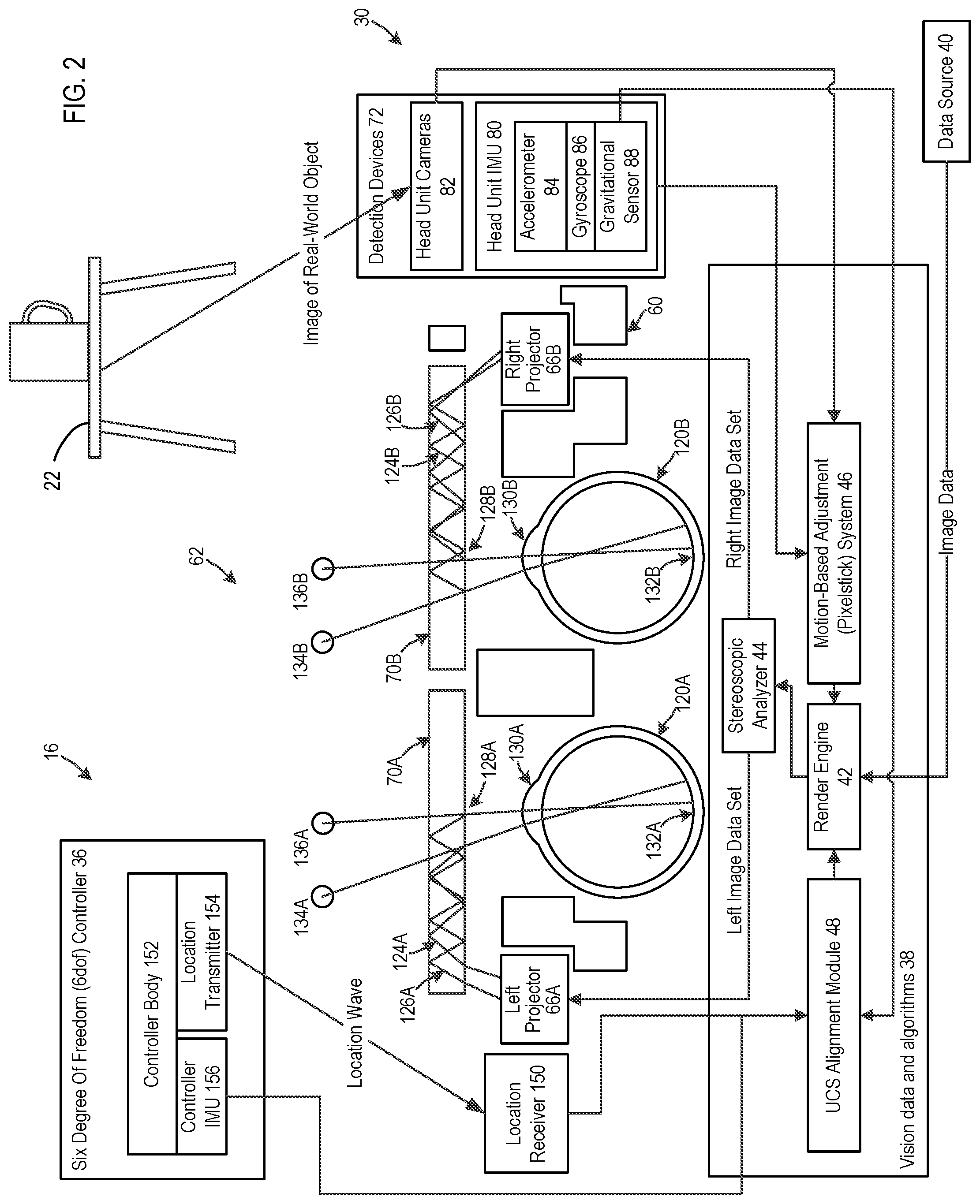
[0009] FIG. 2 is a schematic diagram that shows components of an augmented reality viewer and eyes of one user in cross-sectional plan view, further components of the augmented reality viewer in block diagram form, and a table inside view;
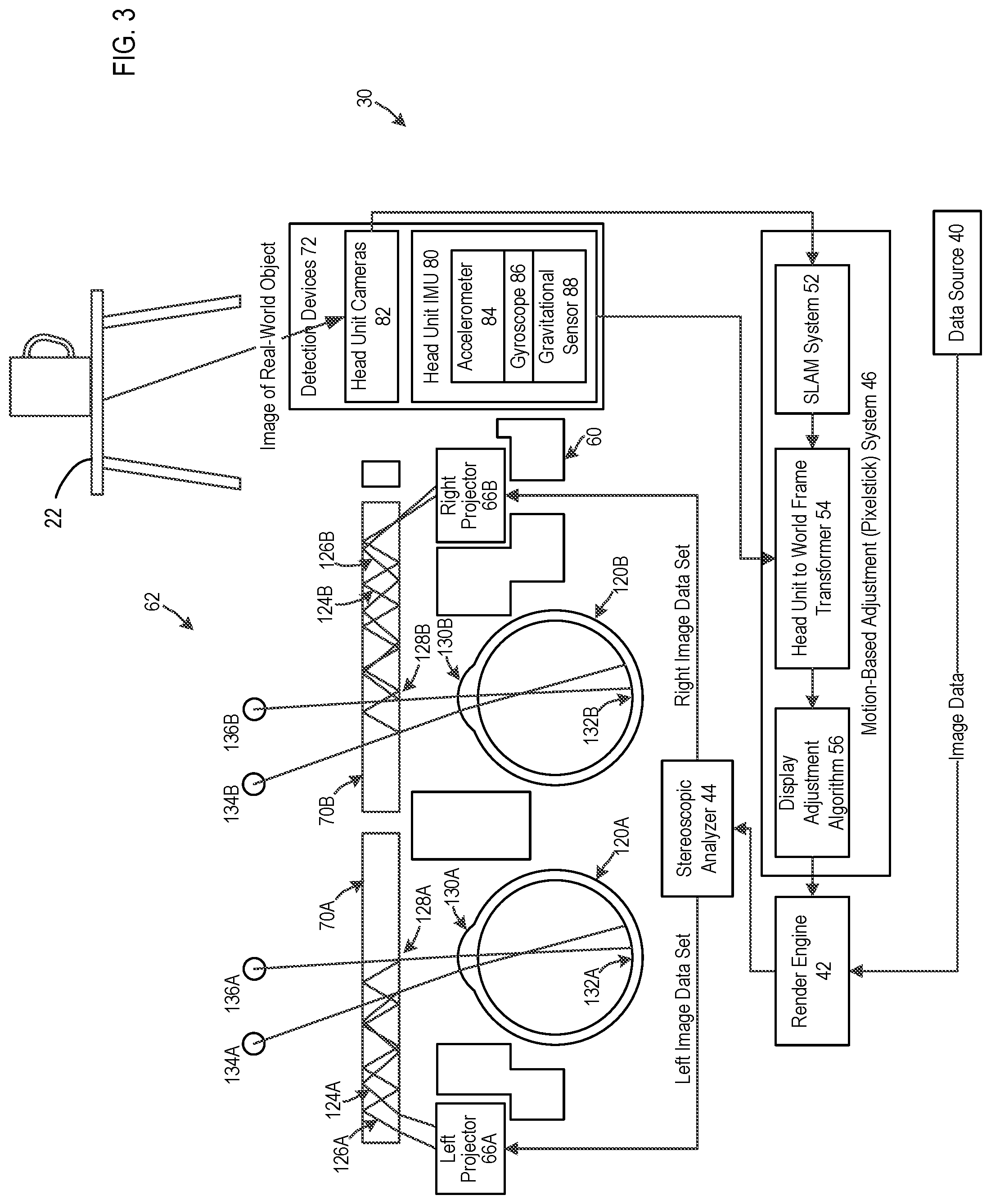
[0010] FIG. 3 is a view similar to FIG. 2 with emphasis on a motion-based adjustment system;
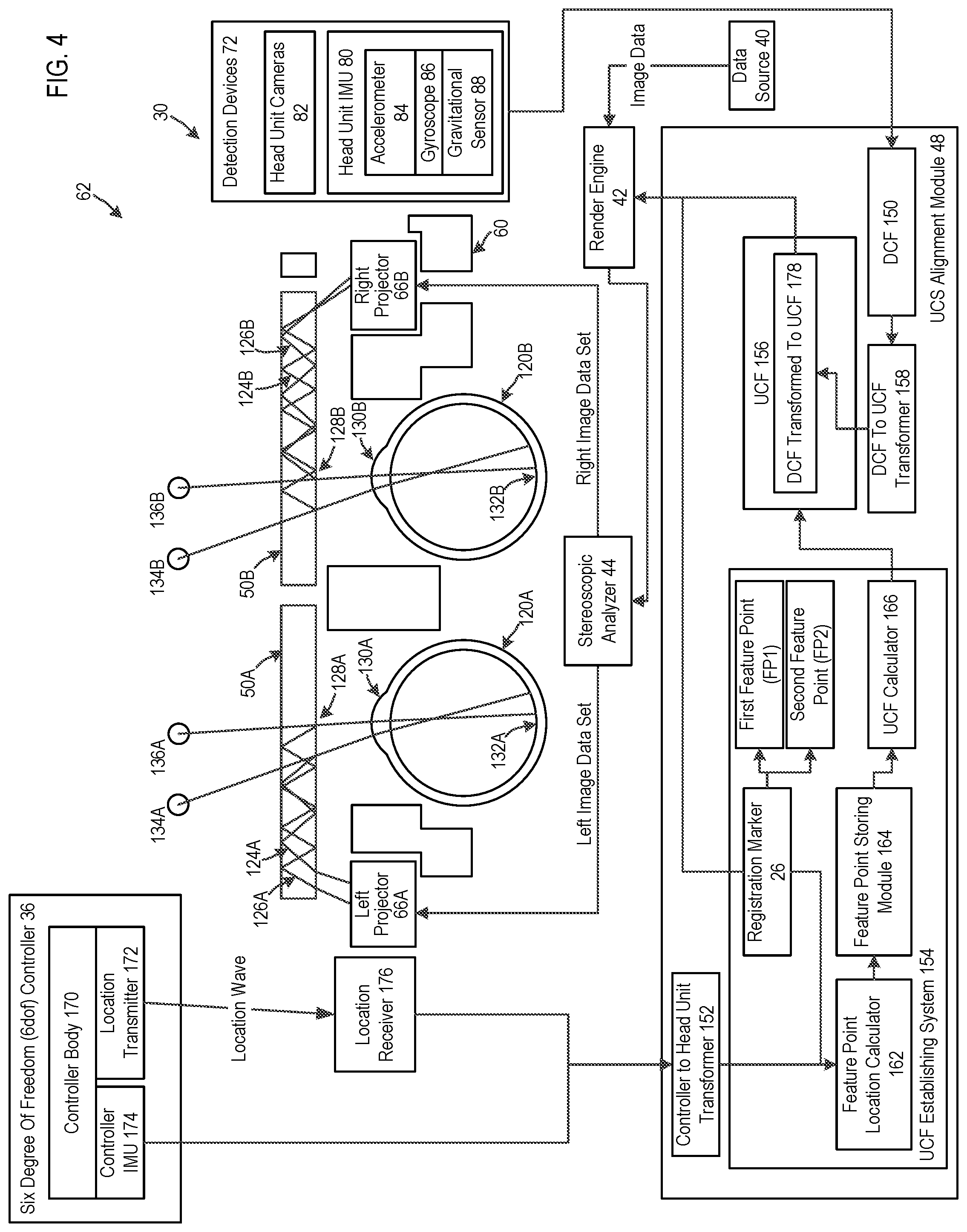
[0011] FIG. 4 is a view similar to FIG. 3 with emphasis on a system that is used for registering local content between the users;
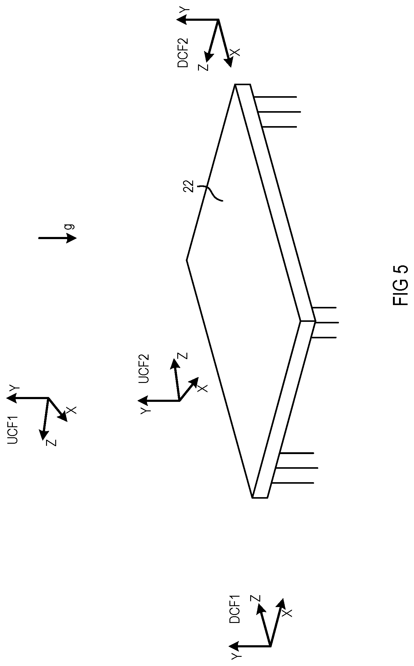
[0012] FIG. 5 is a perspective view illustrating the table and various coordinate frames that reside within vision data and algorithms of the respective augmented reality viewers, and further illustrates a direction of gravitational force;
[0013] FIG. 6 is a view similar to FIG. 5 illustrating how the users select first and second feature points;
[0014] FIG. 7 is a view similar to FIG. 6 illustrating how coordinate frames are transformed; and
[0015] FIG. 8 is a block diagram of a machine in the form of a computer that can find application in the present invention system, in accordance with one embodiment of the invention.
DETAILED DESCRIPTION OF THE INVENTION
[0016] FIG. 1 of the accompanying drawings illustrates first and second users 10 and 12 that interact with a viewing system 14, according to one or more embodiments of the invention. The viewing system 14 includes a respective augmented reality viewer 16 for each user 10 and 12, a network 18 and a server 20. The first and second users are located within an environment with a real object in the form of a table 22. Various renderings are viewable by the users 10 and 12 using the augmented reality viewers 16, including a rendering of local content 24 and renderings of registration markers 26.
[0017] Each augmented reality viewer 16 includes a head unit 30, a belt pack 32, a cable connection 34, and a six degrees of freedom (6 dof) controller 36. The respective user 10 or 12 secures the head unit 30 to their head and the belt pack 32 remotely from the head unit 30 on their waist (or other suitable location, such as a backpack, for example). The cable connection 34 connects the head unit 30 to the belt pack 32. The head unit 30 includes technologies that are used to display a virtual object or objects to a user while the user is permitted to see real objects such as the table 22. The belt pack 32 includes primarily processing and communications capabilities of the augmented reality viewer 16. In another embodiment, the processing and communication capabilities may reside entirely in the head unit 30, thus dispensing the need for the belt pack 32.
[0018] The belt pack 32 is connected via a wireless connection to the network 18. The server 20 is connected to the network 18 and holds data representative of local content. The belt pack 32 downloads the local content from the server 20 via the network 18. The belt pack 32 provides the data via the cable connection 34 to the head unit 30. The head unit 30 typically includes a display that includes a light source, which could be laser light or LED light or any other suitable light, and a waveguide that guides the light so that the light is received by a retina of each eye of the respective user 10 or 12. The display of the head unit 30 creates slightly different images for left and right eyes of the user 10 or 12 so that a brain of the user 10 or 12 perceives the light as a three-dimensional image of the local content 24. The proportions of the local content 24 and its location and distance from the user 10 or 12 are determined by the data representing local content 24 and various coordinate frames that are used to display the local content 24 to the respective user 10 or 12.
[0019] The local content 24 is displayed to both users 10 and 12 in the same location relative to the table 22. In the given example, the local content 24 is a head of a character that faces towards the first user 10 from the viewpoint of the first user 10 and from the viewpoint of the second user 12.
[0020] The 6 dof controller 36 includes a location transmitter and the head unit 30 includes a location receiver. The location transmitter transmits a location signal and the location receiver receives the location signal. The location signal includes data representing a location of the location transmitter, and therefore the 6 dof controller 36, relative to the location receiver and therefore the head unit 30.
[0021] In use, the user 10 or 12 mounts the head unit 30 to their head and the belt pack 32 to their waist. The belt pack 32 downloads image data over the network 18 from the server 20. The user 10 or 12 can see the table 22 through a display of the head unit 30. A projector forming part of the head unit 30 receives the image data from the belt pack 32 and generates light based on the image data. The light travels through one or more waveguides forming part of the display of the head unit 30. The light then leaves the waveguide and propagates on to a retina of an eye of the user 10 or 12. The projector generates the light in a pattern that is replicated on to a retina of the eye of the user 10 or 12. The light that falls on the retina of the eye of the user 10 or 12 has a selected field of depth so that the user 10 or 12 perceives an image at a preselected depth behind the waveguide. In addition, both eyes receive slightly different images so that a brain of the user 10 or 12 perceives a three-dimensional image or images at selected distances from the head unit 30. In the present example, both users 10 and 12 perceive the local content 24 as an augmentation to seeing the table 22.
[0022] Each user 10 or 12 can also perceive one of the registration markers 26 in three-dimensions. A location of a registration marker 26 is always in a set direction relative to the 6 dof controller 36 that is held by the respective user 10 or 12. The registration marker 26 thus moves left to right and forward and backward as the respective 6 dof controller 36 is moved left and right and forwards and backwards. The registration marker 26 attaches itself to a surface of a real object. When a user thus moves the 6 dof controller 36, the registration marker 26 may for example move across a surface of the table 22. The user 10 or 12 can then select particular points on the table 22, for example one or more corners of the table 22.
[0023] The local content 24 and the registration markers 26 are not visible from the perspective of the drawing and are only visible to the users 10 and 12 due their use of the augmented reality viewers 16. The local content 24 and the registration markers 26 are initially data structures that reside within vision data and algorithms in the belt pack 32. The data structures then manifest themselves as light when the projectors in the head units 30 generate light based on the data structures. Although the local content 24 and the registration markers 26 have no existence in three-dimensional space in front of the users 10 and 12 (e.g. are virtual objects), they are represented in FIG. 1 in three-dimensional space. The visualization of computer data in three-dimensional space is used throughout this description to illustrate how the data structures that facilitate the renderings that are perceived by the users 10 and 12 related to one another within the data structures of the vision algorithms in the belt pack 32.
[0024] FIG. 2 illustrates one of the augmented reality viewers 16 in more detail, including the head unit 30, the 6 dof controller 36, and vision data and algorithms 38. In some embodiments, the vision data and algorithms 38 reside primarily with the belt pack 32 in FIG. 1. In other embodiments, the vision data and algorithms 38 may reside entirely within a head unit or may be split between a head unit and a belt pack.
[0025] FIG. 2 further includes a data source 40. In the present example, the data source 40 includes image data that is received from the server 20 in FIG. 1 and then stored on a storage device of the belt pack 32. The image data may, for example, be three-dimensional image data that can be used to render the local content 24. The image data may be time sequenced data that allows for the creation of a video that moves in two- or three-dimensions in a predefined or non-predefined sequence, and may be located on a real-world object such as the table 22 in FIG. 1.
[0026] The vision data and algorithms 38 include a render engine 42, a stereoscopic analyzer 44, a motion-based adjustment (Pixelstick) system 46, and a uniform coordinate system (UCS) alignment module 48.
[0027] The render engine 42 is connected to the data source 40, the motion-based adjustment system 46, and the UCS alignment module 48. The render engine 42 is capable of receiving inputs from various systems, in the present example the motion-based adjustment system 46 and the UCS alignment module 48.
[0028] As shown in FIG. 3, the motion-based adjustment system 46 includes a simultaneous localization and mapping (SLAM) system 52, a head unit to world frame transformer 54, and a display adjustment algorithm 56. The render engine 42 is connected to the display adjustment algorithm 56. The display adjustment algorithm 56 receives an input from the head unit to world frame transformer 54. The head unit to world frame transformer 54 is connected to the SLAM system 52. The SLAM system 52 is capable of receiving image data, analyzing the image data for purposes of determining objects within images of the image data, and recording the locations of the image data. The head unit to world frame transformer 54 is capable of transforming a head unit coordinate frame to a world coordinate frame.
[0029] The stereoscopic analyzer 44 is connected to the render engine 42. The stereoscopic analyzer 44 is capable of determining left and right image data sets from a data stream that is provided by the render engine 42.
[0030] The head unit 30 includes a head unit body 60 and display system 62. The head unit body 60 has a shape that fits over a head of a user. The display system 62 is secured to the head unit body 60.
[0031] The display system 62 includes left and right projectors 66A and 66B, left and right waveguides 70A and 70B and detection devices 72. The left and right projectors 66A and 66B are connected to power supplies. Each projector 66A or 66B has a respective input for image data to be provided to the respective projector 66A or 66B. The respective projector 66A or 66B, when powered, generates light in two-dimensional patterns and emanates the light therefrom. The left and right waveguides 70A and 70B are positioned to receive light from the left and right projectors 66A and 66B, respectively. The left and right waveguides 70A and 70B are transparent waveguides.
[0032] The detection devices 72 include a head unit inertial motion unit (IMU) 80 and one or more head unit cameras 82. The head unit IMU 80 includes an accelerometer 84 (or more than one accelerometer), a gyroscope 86 (or more than one gyroscope) and a gravitational sensor 88. The components of the IMU are typically formed in a semiconductor chip. The accelerometer and the gyroscope are capable of detecting movement of the head unit IMU 80 and the head unit body 60, including movement along three orthogonal axes and rotation about the orthogonal axes. The gravitational sensor 88 is capable of detecting the direction of gravitational force.
[0033] The head unit cameras 82 continually capture images from an environment around the head unit body 60. The images can be compared to one another to detect movement of the head unit body 60 and the head of the user wearing the head unit body 60.
[0034] The SLAM system 52 is connected to the head unit cameras 82. The head unit to world frame transformer 54 relies on data from the SLAM system 52 and the head unit IMU 80 to transform a coordinate frame of the head unit 30 to a world coordinate frame, namely a coordinate frame that includes a real object such as the table 22 in FIG. 1.
[0035] In use, a user mounts the head unit body 60 to their head. Components of the head unit body 60 may, for example, include a strap (not shown) that wraps around the back of the head of the user. The left and right waveguides 70A and 70B are then located in front of left and right eyes 120A and 120B of the user.
[0036] The render engine 42 receives image data from the data source 40. The render engine 42 enters the image data into the stereoscopic analyzer 44. The image data is three-dimensional image data of the local content 24 in FIG. 1. The stereoscopic analyzer 44 analyzes the image data to determine left and right image data sets based on the image data. The left and right image data sets are data sets that represent two-dimensional images that differ slightly from one another for purposes of giving the user 10 a perception of a three-dimensional rendering.
[0037] The stereoscopic analyzer 44 enters the left and right image data sets into the left and right projectors 66A and 66B. The left and right projectors 66A and 66B then create left and right light patterns. The components of the display system 62 are shown in plan view, although it should be understood that the left and right patters are two-dimensional patterns when shown in front elevation view. Each light pattern includes a plurality of pixels. For purposes of illustration, light rays 124A and 126A from two of the pixels are shown leaving the left projector 66A and entering the left waveguide 70A. The light rays 124A and 126A reflect from sides of the left waveguide 70A. It is shown that the light rays 124A and 126A propagate through internal reflection from left to right within the left waveguide 70A, although it should be understood that the light rays 124A and 126A also propagate in a direction into the paper using refractory and reflective systems.
[0038] The light rays 124A and 126A exit the left light waveguide 70A through a pupil 128A and then enter a left eye 120A through a pupil 130A of the left eye 120A. The light rays 124A and 126A then fall on a retina 132A of the left eye 120A. In this manner, the left light pattern falls on the retina 132A of the left eye 120A. The user is given the perception that the pixels that are formed on the retina 132A are pixels 134A and 136A that the user perceives to be at some distance on a side of the left waveguide 70A opposing the left eye 120A. Depth perception is created by manipulating the focal length of the light.
[0039] In a similar manner, the stereoscopic analyzer 44 enters the right image data set into the right projector 66B. The right projector 66B transmits the right light pattern, which is represented by pixels in the form of light rays 124B and 126B. The light rays 124B and 126B reflect within the right waveguide 70B and exit through a pupil 128B. The light rays 124B and 126B then enter through a pupil 130B of the right eye 120B and fall on a retina 132B of a right eye 120B. The pixels of the light rays 124B and 126B are perceived as pixels 134B and 136B behind the right waveguide 70B.
[0040] The patterns that are created on the retinas 132A and 132B are individually perceived as left and right images. The left and right images differ slightly from one another due to the functioning of the stereoscopic analyzer 44. The left and right images are perceived in a mind of the user as a three-dimensional rendering.
[0041] As mentioned, the left and right waveguides 70A and 70B are transparent. Light from a real-life object on a side of the left and right waveguides 70A and 70B opposing the eyes 120A and 120B can project through the left and right waveguides 70A and 70B and fall on the retinas 132A and 132B.
[0042] The head unit IMU 80 detects every movement of the head of the user. Should the user 10, for example, move their head counterclockwise and simultaneously move their body together with their head towards the right, such movement will be detected by the accelerometer 84 and gyroscope 86 in the head unit IMU 80. The head unit IMU 80 provides the measurements from the accelerometer 84 and gyroscope 86 to the display adjustment algorithm 56. The display adjustment algorithm 56 calculates a placement value and provides the placement value to the render engine 42. The render engine 42 modifies the image data received from the data source 40 to compensate for the movement of the head of the user. The render engine 42 provides the modified image data to the stereoscopic analyzer 44 for display to the user 10.
[0043] The head unit cameras 82 continually capture images as the user moves their head. The SLAM system 52 analyzes the images and identifies images of objects within the image. The SLAM system 52 analyzes movement of the objects to determine a pose position of the head unit body 60. The SLAM system 52 provides the pose position to the display adjustment algorithm 56. The display adjustment algorithm 56 uses the pose position to further refine the placement value that the display adjustment algorithm 56 provides to the render engine 42. The render engine 42 thus modifies the image data received from the data source 40 based on a combination of the motion sensors in the head unit IMU 80 and images taken by the head unit cameras 82. By way of a practical example, if the user rotates their head to the right, a location of the local content 24 rotates to the left within the view of the user thus giving the user the impression that the location of the local content 24 remains stationary relative to the table 22 and other real-world objects.
[0044] Referring to FIG. 4, the UCS alignment module 48 includes a device coordinate frame (DCF) 150, a controller to head unit transformer 152, a user coordinate frame (UCF) establishing system 154, a UCF 156, and a DCF to UCF transformer 158.
[0045] The DCF 150 is connected to the gravitational sensor 88 through a combination of hardware, software, and firmware. The gravitational sensor 88 measures a direction of gravitational force relative to the head unit body 60. The DCF 150 is a coordinate frame with three orthogonal axes, wherein one of the axes is aligned with the direction of gravitational force.
[0046] The UCF establishing system 154 includes the registration marker 26 shown in FIG. 1, a feature point location calculator 162, a feature point storing module 164, and a user coordinate frame calculator 166. The feature point location calculator 162 is connected through routines and calls to the controller to head unit transformer 152 and receives an input from the registration marker 26. The registration marker 26 is used to select a first feature point (FP1) and a second feature point (FP2). The feature point storing module 164 is connected to the feature point location calculator 162 and stores locations of the first and second feature points FP1 and FP2. The user coordinate frame calculator 166 receives the locations of the feature points FP1 and FP2 from memory and calculates the UCF 156 based on the locations of the first and second feature points, FP1 and FP2.
[0047] The 6 dof controller 36 includes a controller body 170, a location transmitter 172 and a controller IMU 174. The controller body 170 has a shape that is convenient for a user to hold on to. The location transmitter 172 and the controller IMU 174 are mounted within the controller body 170. A battery (not shown) within the controller body 170 is used to power the location transmitter 172 and the controller IMU 174.
[0048] The head unit 30 includes a location receiver 176. The location receiver 176 is mounted in a stationary position to the head unit body 60.
[0049] In use, the user holds the controller body 170 in one of their hands. The user can move the controller body 170 in three orthogonal directions and rotate the controller body 170 about three orthogonal axes. The location transmitter 172 continually transmits a location wave and the location receiver 176 receives the location wave. The location wave includes data indicative of the location of the location transmitter 172 relative to the location receiver 176. Because the location transmitter 172 is stationary within the 6 dof controller 36 and the location receiver 176 is stationary within the head unit 30, the location wave includes data representing a relationship between the 6 dof controller 36 and the head unit 30. The controller to head unit transformer 152 receives data from the location receiver 176 and calculates the location of the 6 dof controller 36 relative to the head unit 30. The controller IMU 174 includes one or more accelerometers and one or more gyroscopes. Data from the controller IMU 174 is wirelessly transmitted from the 6 dof controller 36 and received via a combination of hardware, firmware and software by the controller to head unit transformer 152. The controller to head unit transformer 152 combines the data from the location receiver 176 and the controller IMU 174 in a "fusion" routine. By fusing data from the location transmitter 172 and the controller IMU 174, jitter is reduced when compared to the use of the location transmitter 172 alone.
[0050] The registration marker 26 is provided to the render engine 42 and is visualized to the user in a similar manner as the image data from the data source 40. As mentioned above, the user can move the registration marker 26 by moving the 6 dof controller 36. The user uses the registration marker 26 to select the first feature point FP1 and the second feature point FP2. When the user selects the first and second feature points FP1 and FP2, the feature point location calculator 162 calculates a location of the respective feature point FP1 or FP2 within a world frame. The feature point storing module 164 stores the locations of the first and second feature points FP1 and FP2. The UCF calculator 166 then calculates the UCF 156 based on the locations of the first and second feature points FP1 and FP2. The UCF calculator 166 then stores the UCF 156 in memory.
[0051] The DCF to UCF transformer 158 transforms the DCF 150 to the UCF 156, resulting in the DCF transformed to UCF 178.
[0052] Each one of the users 10 and 12 in FIG. 1 has a different DCF 150 and a different UCF 156 and hence a different DCF transformed to UCF 178. The users 10 and 12 agree on the locations (e.g. verbally agree) on the table 22 where they select the first and second feature points FP1 and FP2. The locations of the first and second feature points FP1 and FP2 appear different from the perspectives of each user 10 and 12 and their mathematical locations are also calculated to be different within the feature point location calculator 162 of each augmented reality viewer 16. However, because the users 10 and 12 select the same feature points FP1 and FP2 within the real world, namely on the table 22, the local content 24 can be rendered in the same location relative to the table 22 from the perspectives of both of the users 10 and 12.
[0053] FIG. 5 illustrates the respective coordinate frames before either user establishes a uniform coordinate frame. Each augmented reality viewer has a respective DCF (DCF1 and DCF2). One of the axes (the Y-axis) is aligned with the direction of gravitational force (g) and the other two axes (the X-axis and the Z-axis) are fixed relative to the head unit 30. Neither user has established a UCF. For purposes of illustration only, arbitrary UCF's (UCF1 and UCF2) are shown in the figure and are only included in the figure to show that there is no uniformity in coordinate frames between the augmented reality viewers 16 that are used by the first and second users 10 and 12 (FIG. 1).
[0054] FIG. 6 illustrates the establishment of a UCF for each augmented reality viewer (UCF1 and UCF2). Each user 10 and 12, from their perspective, selects the first and second feature points FP1 and FP2 on the table 22. The respective augmented reality viewers of the respective users then calculate the respective UCF's (UCF1 and UCF 2). Both UCF's (UCF1 and UCF 2) are located and oriented on the same location on the table 22.
[0055] FIG. 7 illustrates the transformations that are made by the respective DCF to UCF transformers 158 (FIG. 4) of the respective augmented reality viewers. Each augmented reality viewer transforms its respective DCF (DCF1 or DCF2) to its respective UCF (UCF1 or UCF2), respectively. The local content 24 (FIG. 1) is displayed to the respective user based on the respective transformation from the respective DCF (DCF1 or DCF2) to the respective UCF (UCF1 or UCF2).
[0056] The viewing system 14 can readily be expanded for use by three, four or more viewing augmented reality viewers that are used by three, four or more users. Each augmented reality viewer has its own DCF (DCF1, DCF2, DCF3 . . . Dafne) and calculates a respective UCF (UCF1, UCF2, UCF3 . . . UCFn) using a respective pair of feature points (FP1 and FP2). Each augmented reality viewer then transforms its respective DCF (e.g., DCF4) to a respective UCF (e.g., UCF4) as described above.
[0057] FIG. 8 shows a diagrammatic representation of a machine in the exemplary form of a computer system 900 within which a set of instructions, for causing the machine to perform any one or more of the methodologies discussed herein, may be executed, according to some embodiments. In alternative embodiments, the machine operates as a standalone device or may be connected (e.g., networked) to other machines. Further, while only a single machine is illustrated, the term "machine" shall also be taken to include any collection of machines that individually or jointly execute a set (or multiple sets) of instructions to perform any one or more of the methodologies discussed herein.
[0058] The exemplary computer system 900 includes a processor 902 (e.g., a central processing unit (CPU), a graphics processing unit (GPU) or both), a main memory 904 (e.g., read only memory (ROM), flash memory, dynamic random access memory (DRAM) such as synchronous DRAM (SDRAM) or Rambus DRAM (RDRAM), etc.), and a static memory 906 (e.g., flash memory, static random access memory (SRAM), etc.), which communicate with each other via a bus 908.
[0059] The computer system 900 may further include a disk drive unit 916, and a network interface device 920.
[0060] The disk drive unit 916 includes a machine-readable medium 922 on which is stored one or more sets of instructions 924 (e.g., software) embodying any one or more of the methodologies or functions described herein. The software may also reside, completely or at least partially, within the main memory 904 and/or within the processor 902 during execution thereof by the computer system 900, the main memory 904 and the processor 902 also constituting machine-readable media.
[0061] The software may further be transmitted or received over a network 18 via the network interface device 920.
[0062] The computer system 900 includes a driver chip 950 that is used to drive projectors to generate light. The driver chip 950 includes its own data store 960 and its own processor 962.
[0063] While the machine-readable medium 922 is shown in an exemplary embodiment to be a single medium, the term "machine-readable medium" should be taken to include a single medium or multiple media (e.g., a centralized or distributed database, and/or associated caches and servers) that store the one or more sets of instructions. The term "machine-readable medium" shall also be taken to include any medium that is capable of storing, encoding, or carrying a set of instructions for execution by the machine and that cause the machine to perform any one or more of the methodologies of the present invention. The term "machine-readable medium" shall accordingly be taken to include, but not be limited to, solid-state memories, optical and magnetic media, and carrier wave signals.
[0064] While certain exemplary embodiments have been described and shown in the accompanying drawings, it is to be understood that such embodiments are merely illustrative and not restrictive of the current invention, and that this invention is not restricted to the specific constructions and arrangements shown and described since modifications may occur to those ordinarily skilled in the art.
* * * * *
D00000
D00001
D00002
D00003
D00004
D00005
D00006
D00007
D00008
XML
uspto.report is an independent third-party trademark research tool that is not affiliated, endorsed, or sponsored by the United States Patent and Trademark Office (USPTO) or any other governmental organization. The information provided by uspto.report is based on publicly available data at the time of writing and is intended for informational purposes only.
While we strive to provide accurate and up-to-date information, we do not guarantee the accuracy, completeness, reliability, or suitability of the information displayed on this site. The use of this site is at your own risk. Any reliance you place on such information is therefore strictly at your own risk.
All official trademark data, including owner information, should be verified by visiting the official USPTO website at www.uspto.gov. This site is not intended to replace professional legal advice and should not be used as a substitute for consulting with a legal professional who is knowledgeable about trademark law.