Capillary Device For Use In Heat Pipe And Method Of Manufacturing Such Capillary Device
McGlen; Ryan James ; et al.
U.S. patent application number 17/521273 was filed with the patent office on 2022-04-28 for capillary device for use in heat pipe and method of manufacturing such capillary device. The applicant listed for this patent is Aavid Thermal Corp.. Invention is credited to Ryan James McGlen, John Gilbert Thayer.
| Application Number | 20220128312 17/521273 |
| Document ID | / |
| Family ID | 1000006079007 |
| Filed Date | 2022-04-28 |


View All Diagrams
| United States Patent Application | 20220128312 |
| Kind Code | A1 |
| McGlen; Ryan James ; et al. | April 28, 2022 |
CAPILLARY DEVICE FOR USE IN HEAT PIPE AND METHOD OF MANUFACTURING SUCH CAPILLARY DEVICE
Abstract
A capillary device (102) for use in a heat pipe in which heat is transferred from at least one evaporation region to at least one condensation region by means of evaporated working fluid is disclosed. The capillary device comprises a body portion defining chambers (108) containing powdered material (110) therein, wherein at least part of the periphery of at least one said chamber is porous to allow flow of condensed working fluid, by means of capillary action, through said powdered material in said chamber when flowing from a condensation region to an evaporation region.
| Inventors: | McGlen; Ryan James; (Northumberland, GB) ; Thayer; John Gilbert; (Lancaster, PA) | ||||||||||
| Applicant: |
|
||||||||||
|---|---|---|---|---|---|---|---|---|---|---|---|
| Family ID: | 1000006079007 | ||||||||||
| Appl. No.: | 17/521273 | ||||||||||
| Filed: | November 8, 2021 |
Related U.S. Patent Documents
| Application Number | Filing Date | Patent Number | ||
|---|---|---|---|---|
| 16254684 | Jan 23, 2019 | 11168944 | ||
| 17521273 | ||||
| 14119814 | Mar 14, 2014 | |||
| PCT/EP2012/059681 | May 24, 2012 | |||
| 16254684 | ||||
| Current U.S. Class: | 1/1 |
| Current CPC Class: | F28D 15/046 20130101; F28D 15/04 20130101; Y10T 29/10 20150115; F28D 15/0233 20130101; Y10T 29/49353 20150115; B23P 15/26 20130101; Y10T 29/49396 20150115 |
| International Class: | F28D 15/04 20060101 F28D015/04; F28D 15/02 20060101 F28D015/02; B23P 15/26 20060101 B23P015/26 |
Foreign Application Data
| Date | Code | Application Number |
|---|---|---|
| May 24, 2011 | EP | 11167303.4 |
Claims
1. A heat transfer pipe in which heat is transferred from an evaporation region to a condensation region by means of working fluid, the heat transfer pipe comprising: a body portion defining a central channel, the central channel extending between and in fluid communication with the evaporation region and the condensation region; and a capillary structure within the body portion and surrounding the central channel, wherein the capillary structure comprises a plurality of spaced-apart porous protrusions extending radially into the central channel with each protrusion separated from an adjacent protrusion by a gap therebetween; wherein the heat transfer pipe includes successive layers of metal powder that are located over a donor material and have been melted by an energetic beam, wherein the successive layers at least partially define the plurality of porous protrusions.
2. A heat transfer pipe according to claim 1, wherein each porous protrusion of the plurality of porous protrusions includes a hollow interior and contains unfused metal powder within the hollow interior.
3. A heat transfer pipe according to claim 2, wherein the successive, melted layers of metal powder at least partially define the hollow interiors.
4. A heat transfer pipe according to claim 2, wherein the unfused metal powder is aluminum.
5. A heat transfer pipe according to claim 1, wherein the body portion is formed from aluminum.
7. A heat transfer pipe according to claim 1, wherein each of the gaps extends in a longitudinal direction parallel to the central channel.
8. A heat transfer pipe according to claim 1, further comprising lattice capillary structures positioned in the gaps between the porous protrusions, wherein each of the capillary lattice structures extends longitudinally along a length of the heat transfer pipe between the evaporation region and the condensation region.
9. A heat transfer pipe according to claim 8, wherein the lattice capillary structures do not extend to the evaporation region.
10. A heat transfer pipe according to claim 8, wherein the lattice capillary structures are formed from a plurality of pores which increase in size along lengths of the lattice capillary structures from the condensation region to the evaporation region.
11. A heat transfer pipe according to claim 1, wherein the successive layers at least partially define the body portion.
12. A heat transfer pipe in which heat is transferred from an evaporation region to a condensation region by means of working fluid, the heat transfer pipe comprising: a solid outer body portion; a porous capillary structure within the outer body portion extending between and in fluid communication with the evaporation region and the condensation region; and a plurality of vapor flow channels embedded in the capillary structure and extending between and in fluid communication with the evaporation region and the condensation region.
13. A heat transfer pipe according to claim 12, wherein the plurality of vapor flow channels is spaced circumferentially around an interior region of the porous structure.
14. A heat transfer pipe according to claim 12, wherein the heat transfer pipe includes successive layers of metal powder that are located over a donor material and have been melted by an energetic beam, wherein the successive layers at least partially define the porous capillary portion and the vapor flow channels.
15. A heat transfer pipe according to claim 12, further comprising a fluid flow passage formed in the center of the porous capillary structure and extending between and in fluid communication with the evaporation region and the condensation region.
16. A heat transfer pipe according to claim 15, further comprising a region of powder metal between the porous capillary structure and the fluid flow passage.
17. A heat transfer pipe in which heat is transferred from an inlet chamber to an outlet chamber by means of working fluid, the heat pipe comprising: an outer body portion; and a porous capillary structure positioned within the outer body portion between and in fluid communication with the inlet chamber and the outlet chamber, wherein the porous capillary structure has a porous rigid outer wall and contains unfused powder material.
18. A heat transfer pipe according to claim 17, wherein the inlet chamber and the outlet chamber are divided by the porous capillary structure.
19. A heat transfer apparatus comprising: an evaporation chamber; and a condensation chamber in fluid communication with the evaporation chamber, wherein heat is transferred from the evaporation chamber to the condensation region by means of working fluid, wherein the evaporation chamber includes an outer cylindrical body that defines an interior volume, a porous capillary structure positioned within the interior volume adjacent an interior surface of the outer cylindrical body, wherein the porous capillary structure defines an interior annular chamber enclosing a layer of unfused metal powder, an elongate escape channel positioned between the interior surface of the outer cylindrical body and the interior annular chamber, wherein the elongate escape channel extends from an interior of the porous capillary structure to a first opening in the porous capillary structure, wherein the first opening is in fluid communication with the interior volume and is formed at an end face of the porous capillary structure, a plurality of spaced-apart circumferential vapor channels interconnected by the elongate escape channel, and a central bore surrounded by the interior annular chamber, wherein the central bore extends between the end face and a second opening of the porous capillary structure to the interior volume, wherein the second opening is in fluid communication with the interior volume and positioned opposite the end face.
20. A heat transfer apparatus according to claim 19, wherein the evaporation chamber and the condensation chamber are in the form of a loop heat pipe.
21. A heat transfer pipe comprising: an evaporation region; a condensation region; a body portion extending between and in fluid communication with the evaporation region and the condensation region; and a capillary structure configured to direct working fluid between the evaporation region and the condensation region; wherein the capillary structure includes successive layers of metal powder that have each been melted by an energetic beam to be secured to one or more other layers of the successive layers.
22. The heat transfer pipe of claim 21, wherein the condensation region includes a condenser plate, wherein the condenser plate defines a donor material, wherein the successive layers of metal powder include a first, melted layer of metal powder disposed on the donor material and a second, melted layer of metal powder disposed on the first layer of metal powder.
23. The heat transfer pipe of claim 22, wherein the first, melted layer of metal powder and the second, melted layer of metal powder define a rigid, porous structure that defines a portion of the capillary structure.
24. The heat transfer pipe of claim 23, wherein the capillary structure extends along an interior surface of the body portion.
25. The heat transfer pipe of claim 22, wherein the condenser plate is an aluminum plate, wherein the first, melted layer of metal powder is aluminum powder, and wherein the second, melted layer of metal powder is aluminum powder.
26. The heat transfer pipe of claim 21, wherein the evaporation region includes an evaporator plate, wherein the evaporator plate defines a donor material, wherein the successive layers of metal powder include a first, melted layer of metal powder disposed on the donor material and a second, melted layer of metal powder disposed on the first layer of metal powder.
27. The heat transfer pipe of claim 26, wherein the first, melted layer of metal powder and the second, melted layer of metal powder define a portion of the body portion.
28. The heat transfer pipe of claim 27, wherein the successive layers of metal powder further include additional layers of melted, metal powder that define the capillary structure, wherein the capillary structure is disposed within the body portion.
29. The heat transfer pipe of claim 28, wherein the capillary structure includes rigid, porous protrusions.
30. The heat transfer pipe of claim 21, wherein the body portion also includes successive layers of metal powder that have each been melted by an energetic beam to be secured to one or more other layers of the successive layers of the body portion.
Description
CROSS-REFERENCE TO RELATED APPLICATIONS
[0001] This application is a continuation of U.S. patent application Ser. No. 16/254,684, filed Jan. 23, 2019, which is a continuation of U.S. application Ser. No. 14/119,814, filed Mar. 14, 2014, which is a 371 of international PCT/EP2012/059681, filed May 24, 2012, which claims priority to EP 11167303.4, filed May 24, 2011, issued as EP2715265, the entire contents of each of which are incorporated herein by reference.
[0002] The present invention relates to a device for use in a heat exchange apparatus and to a method of manufacturing such a device. The invention also relates particularly, but not exclusively, to a capillary device for use in a heat pipe.
[0003] Heat pipes are devices in which heat is rapidly removed from a first region by means of evaporation of working fluid, and subsequently released at a second location by means of condensation of the working fluid.
[0004] A conventional loop heat pipe is shown in FIG. 1. The heat pipe 2 comprises a cylindrical evaporator 4 having an inlet 6 for condensed working fluid, the inlet 6 being in communication with a compensation chamber 8, and a cylindrical vapour passage 10 communicating with an outlet 12 for enabling evaporated working fluid to pass to a condenser 14. A capillary structure 16 surrounds a gap 18 surrounding the inlet 6, and is in turn surrounded by the vapour passage 10. The purpose of the compensation chamber 8 is to ensure that the gap 18 is always filled with condensed working fluid and to prevent over pressure within the loop heat pipe, since condensed working fluid is displaced into the compensation chamber as vapour is generated.
[0005] During operation of the heat pipe 2, heat in the vicinity of the evaporator 4, for example generated by electronics operating in a confined space, travels in the direction of arrows A to cause evaporation of the working fluid in the capillary structure 16. The evaporated working fluid then passes along vapour passage 10 and outlet 12 to the condenser 14 where heat can be more easily removed in the direction of arrows B and condensed working fluid is returned via inlet 6 and compensation chamber 8 to fill the gap 18 surrounding the inlet 6. Condensed working fluid is then transferred from the gap 18 to the vapour passage 10 through the capillary structure 16 by means of capillary action. The capillary structure 16 of the heat pipe 2 is manufactured by sintering of fine metal powder and subsequent machining to form the flow passages.
[0006] This arrangement suffers from the drawback that the sintering technique can only be carried out on a limited range of materials, and the complexity of possible shapes and dimensions of flow channels is limited by the machining technique.
[0007] A conventional axially grooved heat pipe 16 is shown in FIG. 2. The heat pipe 16 has capillary structure 19 which is extruded from a suitable material and comprises a plurality of axial grooves 20 surrounding a central channel 22. Vaporised working fluid travels along the central channel 22 from a hot end of the heat pipe 16 to a cold end, and condensed working fluid travels in the opposite direction along grooves 20 by means of capillary action. The arrangement shown in FIG. 2 suffers from the drawback that the range of shapes and sizes of grooves 22 is limited by extrusion techniques, as a result of which the grooves 22 have channel widths in the region of 0.1 to 1 mm wide. This dimension of channel width is too large to provide sufficient surface tension to entrain condensed working fluid when operating against gravity, as a result of which this type of device can generally only be used in space applications such as satellite cooling.
[0008] Preferred embodiments of the present invention seek to overcome one or more of the above disadvantages of the prior art.
[0009] According to an aspect of the present invention, there is provided a capillary device for use in a heat transfer apparatus in which heat is transferred from at least one first region to at least one second region by means of working fluid, the capillary device comprising a body portion defining at least one chamber containing unmelted powdered material therein, wherein at least part of the periphery of at least one said chamber is porous to allow flow of condensed working fluid through said unmelted powdered material in said chamber by means of capillary action.
[0010] By providing at least one chamber containing unmelted powdered material therein, wherein at least part of the periphery of at least one said chamber is porous to allow flow of condensed working fluid through said unmelted powdered material in said chamber, this provides the advantage in the case of a heat pipe using capillary action to transport condensed working fluid, of increasing fluid transfer by means of capillary action, while minimising thermal conduction into the powdered material of the chamber, which in turn minimises the effect of parasitic heating of the working fluid passing through the powdered material. This in turn improves the cooling performance of a heat pipe incorporating the device.
[0011] The capillary device may be adapted to be used in a heat pipe in which heat is transferred from at least one evaporation region to at least one condensation region by means of evaporated working fluid, and at least part of the periphery of at least one said chamber may be porous to allow flow of condensed working fluid, by means of capillary action, through said unmelted powdered material in said chamber when flowing from a condensation region to an evaporation region.
[0012] At least a portion of said body portion in the vicinity of an evaporation region may have a porosity different from a porosity of at least a portion of said body portion remote from said evaporation region.
[0013] This provides the advantage of enabling the capillary action to be tailored to the various parts of the device and fluid flow to thereby be maximised.
[0014] The body portion may surround an elongate channel and at least one said chamber may be located between at least part of said channel and an evaporation region in use.
[0015] This provides the advantage of enhancing capillary action and thereby increasing fluid flow, thereby enabling the apparatus to be used when subject to gravity.
[0016] A plurality of said chambers may be spaced apart around the periphery of, and protruding into, said channel.
[0017] The capillary device may further comprise at least one vapour flow passage in said body portion for allowing flow of evaporated working fluid from an evaporation region to a condensation region.
[0018] At least part of the periphery of at least one said vapour flow passage may be porous.
[0019] Said body portion may comprise at least one support portion adapted to resist compressive forces applied to the capillary device, wherein at least part of at least one said support portion is porous to allow flow of condensed working fluid therethrough.
[0020] By providing at least one support portion which can contribute to the capillary action, this provides the advantage of reducing the weight of the capillary device.
[0021] According to another aspect of the present invention, there is provided a heat transfer apparatus comprising at least one capillary device as defined above.
[0022] At least one said capillary device may be connected to a plurality of condenser devices.
[0023] This provides the advantage of enabling a capillary device to be constructed by means of selective melting of powdered material to thereby enable a wider range of dimensions and properties of capillary structure to be provided, while enabling condenser devices manufactured according to simpler techniques such as extrusion to be used.
[0024] According to a further aspect of the present invention, there is provided a method of manufacturing a body portion of a capillary device for use in a heat transfer apparatus in which heat is transferred from at least one first region to at least one second region by means of working fluid, the method comprising forming successive layers of said body portion by means of selective melting of powdered material by means of an energetic beam, such that at least part of said body portion is porous to enable flow of condensed working fluid therethrough.
[0025] By forming successive layers of said body portion by means of selective melting of powdered material by means of an energetic beam, this provides the advantage of enabling a wider range of shapes of device to be constructed, and a wider range of materials to be used. This is particularly advantageous in the case of heat pipes which use capillary action to transfer condensed working fluid from a condensation region to an evaporation region. For example, the method of the present invention enables body portions of complex shapes having voids or hollow portions to save weight to be provided.
[0026] The selective melting of powdered material may provide melted powdered material and unmelted powdered material, and said body portion may define at least one chamber containing unmelted powdered material therein, wherein at least part of the periphery of at least one said chamber is porous.
[0027] The powdered material encapsulated in at least one said chamber may be the same material as the powdered material from which the successive layers are formed.
[0028] This provides the advantage of increasing the ease and speed of manufacture of the capillary device.
[0029] The method may be a method of manufacturing a capillary device adapted to be used in a heat pipe in which heat is transferred from at least one evaporation region to at least one condensation region by means of evaporated working fluid, wherein at least part of the periphery of at least one said chamber is porous to allow flow of condensed working fluid, by means of capillary action, through said powdered material in said chamber when flowing from a condensation region to an evaporation region.
[0030] The body portion may define at least one chamber, and the method may further comprise encapsulating powdered material in at least one said chamber to allow flow of condensed working fluid, by means of capillary action, through said powdered material in said chamber when flowing from a condensation region to an evaporation region.
[0031] The method may further comprise directing at least one stream of powdered material to a location at which said powdered material is melted by means of the energetic beam.
[0032] This provides the advantage of increasing the range of locations at which the device can be used.
[0033] At least one said stream of said powdered material may be constrained in a stream of inert gas.
[0034] Preferred embodiments of the invention will now be described, by way of example only and not in any limitative sense, with reference to the accompanying drawings, in which:
[0035] FIG. 1 is a schematic diagram of a conventional loop heat pipe;
[0036] FIG. 2 is a cross sectional view of a conventional axially grooved heat pipe;
[0037] FIG. 3 is a perspective view of a flat heat pipe of a first embodiment of the present invention with an upper evaporator plate thereof removed;
[0038] FIG. 4 is a schematic view of a process for forming the heat pipe of FIG. 3;
[0039] FIG. 5 is a detailed view of region C of the heat pipe of FIG. 4;
[0040] FIG. 6 is a detailed view of part of a heat pipe of a second embodiment of the present invention;
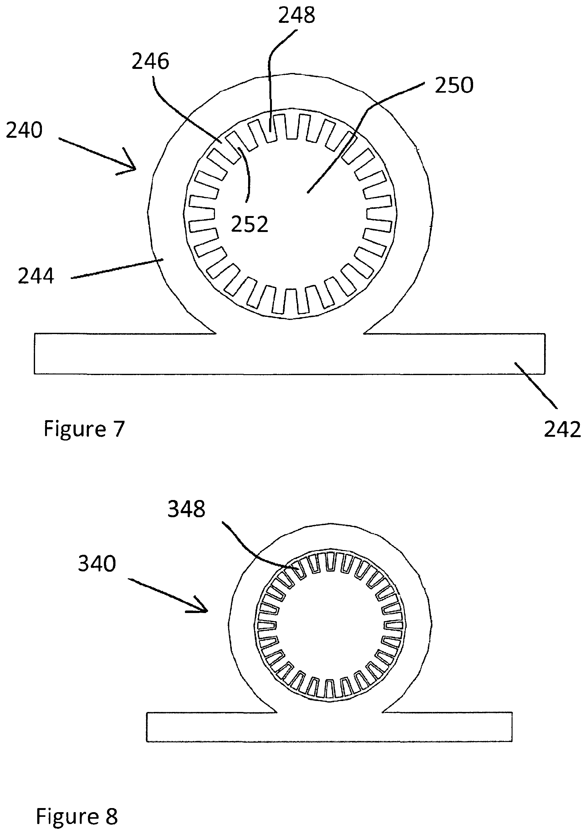
[0041] FIG. 7 is a side cross sectional view of a capillary device of an axially grooved heat pipe of a third embodiment of the present invention;
[0042] FIG. 8 is a side cross sectional view, corresponding to FIG. 7, of a capillary device of an axially grooved heat pipe of a fourth embodiment of the present invention;
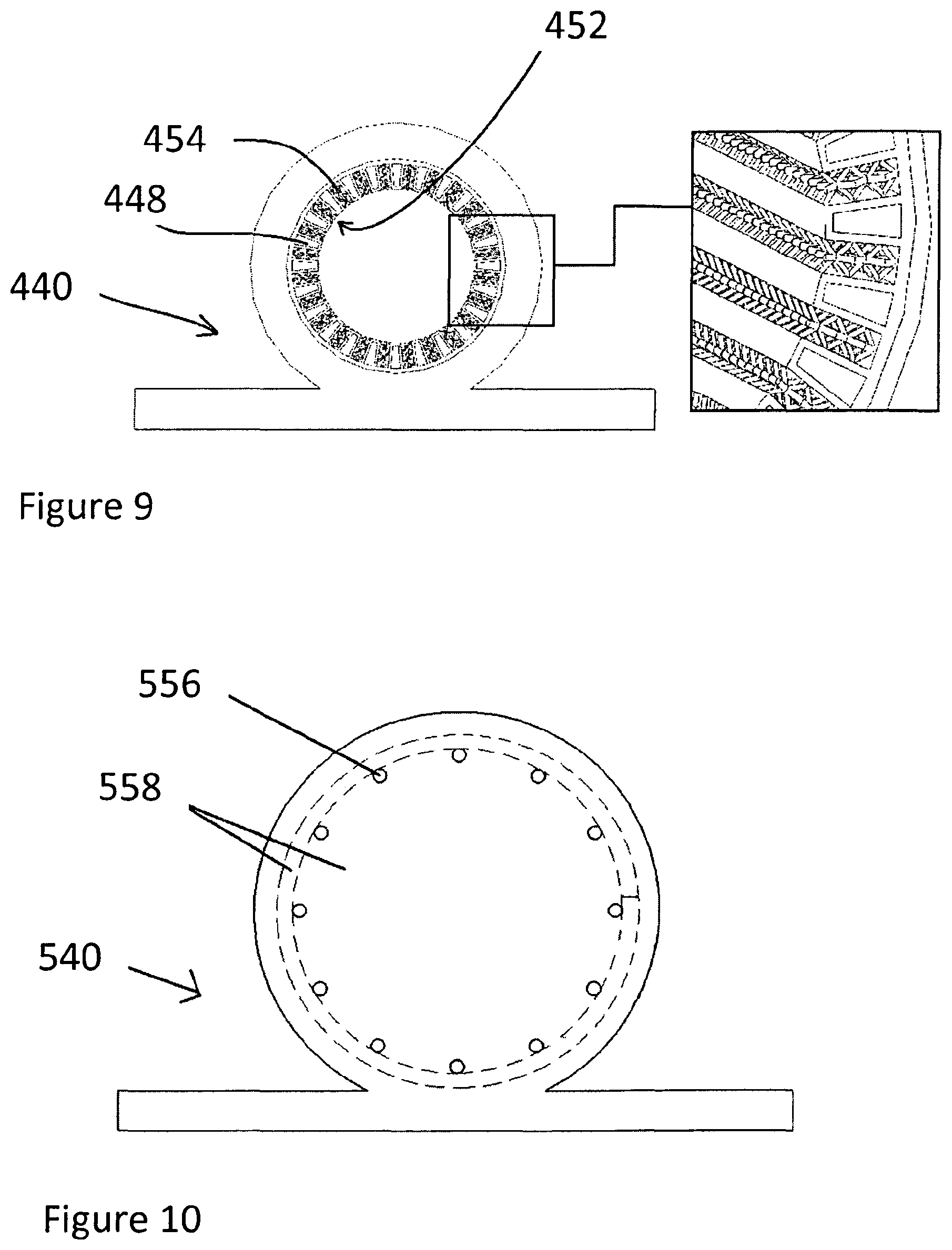
[0043] FIG. 9 is a side cross sectional view, corresponding to FIG. 8, of a capillary device of a fifth embodiment of the present invention;
[0044] FIG. 10 is a side cross sectional view, corresponding to FIG. 9, of a capillary device of a sixth embodiment of the present invention;
[0045] FIG. 11 is a side cross sectional view, corresponding to FIG. 10, of a capillary device of a heat pipe of a seventh embodiment of the present invention;
[0046] FIG. 12 is a schematic view of a heat transfer apparatus of an eighth embodiment of the present invention;
[0047] FIG. 13 is a perspective view of a heat transfer apparatus of a ninth embodiment of the present invention;
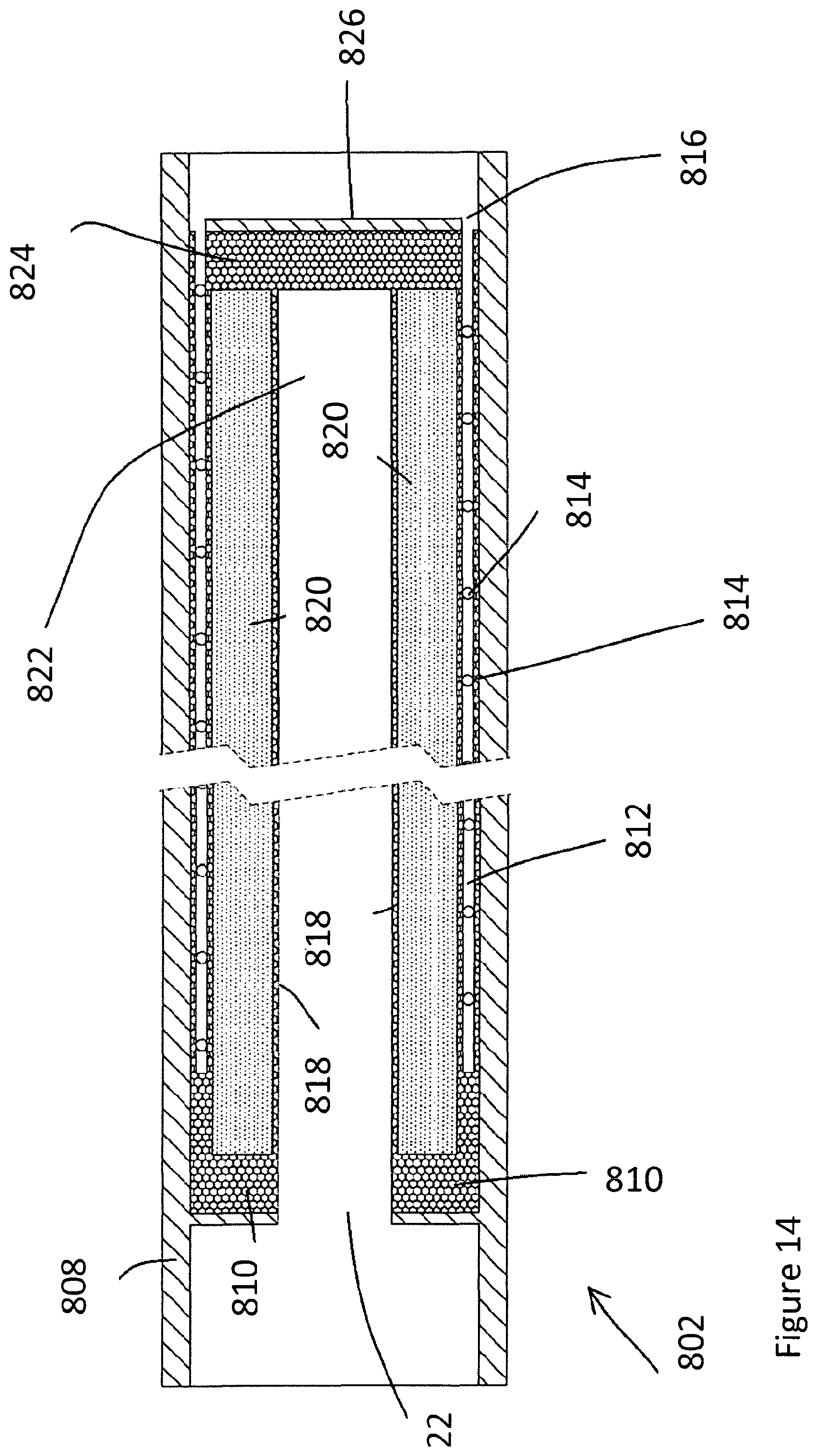
[0048] FIG. 14 is a side cross sectional view of an evaporation apparatus of the heat transfer apparatus of FIG. 13;
[0049] FIG. 15 is a perspective view of a heat transfer apparatus of a tenth embodiment of the present invention;
[0050] FIG. 16 is a view of an evaporation apparatus and a condenser apparatus of the heat transfer apparatus of FIG. 15 with an adiabatic section of the heat transfer apparatus removed; and
[0051] FIG. 17 is a schematic view of a heat transfer apparatus of an eleventh embodiment of the present invention.
[0052] Referring to FIG. 3, a flat heat pipe 102 of a first embodiment of the present invention is formed from aluminium and has an upper evaporator plate 124 (FIG. 4), a lower condenser plate 104 and solid side walls 106. Porous chambers 108 formed from aluminium are arranged between the upper evaporator plate 124 and the lower condenser plate 104, and unmelted aluminium powder 110 is provided inside the chambers 108. The regions 112 between the chambers 108 form a vapour space 109 covered by a layer 122 on the underside of upper evaporator plate 124 such that working fluid such as water is caused by the upper evaporator plate 124 to evaporate and transfer heat via the vapour space 109 to the lower condenser plate 104, and condensed working fluid passes by capillary action through the walls of the chambers 108 and the powdered aluminium 110 in the chambers 108 back to the upper evaporator plate 124. The powdered aluminium 110 enhances fluid flow due to capillary action, but thermal conduction through the powdered aluminium 110 is limited, as a result of which the parasitic heating effect on condensed working fluid passing through the aluminium powder 110 is minimised. This in turn maximises the amount of heat removed from the upper evaporator plate 124 by evaporation of the working fluid.
[0053] The formation of the heat pipe 202 of FIG. 3 is shown in detail with reference to FIGS. 4(a) to 4(h). Initially, as shown in FIG. 4(a), a solid sheet of aluminium is provided, to form lower condenser plate 104 and a layer 114 of powdered aluminium is placed on the donor material, as shown in FIG. 4(b). A high intensity energy beam (not shown) such as a laser beam is then directed onto the layer 114 of powdered material and the path of the beam controlled to selectively melt the layer of powder in the selected regions to form rigid porous regions 116 forming the base of the vapour space 109, separated by regions 118 of unfused powder material which forms the powdered aluminium 110 in the chambers 108. Further layers of powdered aluminium are added and selectively melted in FIGS. 4(c) to 4(e) to form porous side walls 120 of the chambers 108. Similarly, porous upper walls 122 of the vapour space 109 can be formed on the lower surface of solid upper evaporator plate 124 as shown in FIGS. 4(f) to 4(h).
[0054] As shown in greater detail in FIG. 5, each of the chambers 108 encapsulates unmelted powdered material 110, and the vapour space 109 encloses a volume of working fluid at reduced pressure. In use, heat is removed from the upper evaporator plate 124 by evaporation of the working fluid enclosed in chambers 108 and transferred to the lower condenser plate 104 by condensation of the working fluid. The condensed working fluid can pass through the porous walls 120 of chambers 108 into the unfused powder material 110 and returned to the upper evaporator plate 124 through the powder material 110 by means of capillary action.
[0055] Referring to FIG. 6, in which parts common to the embodiment of FIGS. 3 to 5 are denoted by like reference numerals but increased by 100, a heat pipe of a second embodiment of the present invention differs from the arrangement shown in FIGS. 4 and 5 in that one or more support struts 228a, 228b, 228c extend through the interior of one or more of the chambers 208 to assist in capillary transfer of condensed working fluid between the condenser 204 and evaporator 224 plates and to enhance the mechanical strength of the heat pipe. The struts may be a single solid strut 228a, a 3D CAD generated micro capillary strut 228b, or a combination strut 228c consisting of a 3D micro capillary core 230 having a sintered structure 232 mounted on its outer walls. The struts 228b, 228c provide the advantage that by tailoring the 3D CAD geometry and the sintering and/or selective laser melting treatment, the capillary structure can be formed with a graded porosity and permeability, which allows customisation of the mass flow rate of the condensed working fluid around the device. In an alternative arrangement, the sintered structure can be provided on the inside of the strut 228c and the 3D CAD capillary structure on the external surface of the strut.
[0056] Referring to FIG. 7, a capillary device 240 for use in an axially grooved heat pipe of a third embodiment of the present invention is shown. The capillary device 240 is built up by means of selected laser melting of aluminium powder to build up successive layers on a solid donor plate 242 for placing in contact with a heat source, a solid aluminium housing 244, and a capillary structure 246 comprising circumferentially separated porous aluminium protrusions 248 protruding into a central elongate channel 250. By use of the selective laser melting technique used to form the capillary structure 246, the porous protrusions 248 can be separated by smaller channel widths than in the case of the known arrangement shown in FIG. 2, as a result of which the protrusions 248 and gaps 252 therebetween generate significantly enhanced capillary action compared with the arrangement shown in FIG. 2, thereby enabling the heat pipe to operate under the influence of gravity and have improved heat transfer performance.
[0057] In operation, one end of the capillary device 240 is placed in contact with a heat source, and the other end is placed in contact with cooling means to form a condenser. The heat source causes the working fluid to evaporate, and evaporated working fluid travels along the central channel 250 to the condenser. Condensed working fluid travels along the axial gaps 252 between protrusions 248, and is drawn through the porous protrusions 248 by capillary action at the hot end of the heat pipe to maintain the flow of condensed working fluid to the evaporator. The porous protrusions 248 and gaps 252 cooperate to enhance the capillary action to the extent that the capillary action can overcome the effects of gravity.
[0058] Referring to FIG. 8, in which parts common to the embodiment of FIG. 7 are denoted by like reference numerals but increased by 100, a capillary device 340 of a heat pipe of a fourth embodiment of the present invention differs from the arrangement shown in FIG. 7 in that porous protrusions 348 are hollow and contain unfused aluminium powder to enhance the capillary action of flow of condensed working fluid through the porous walls of the protrusions 348 and the powder contained in the protrusions 348.
[0059] FIG. 9 shows a capillary device 440 of a heat pipe of a fifth embodiment of the present invention, in which parts common to the embodiment of FIG. 8 are denoted by like reference numerals but increased by 100. The capillary device 440 of FIG. 9 differs from the arrangement shown in FIG. 8 in that a lattice capillary structure 454 is formed in longitudinal gaps 452 between porous protrusions 448 by means of a selective laser melting or sintering process to form capillary pores having characteristic dimensions below 50 microns at the condenser end of the heat pipe to draw condensed working fluid into the capillary structure. At the condenser, there is also a transition from sintered capillary to lattice within the channel, and as the lattice moves towards the evaporator region, the minimum characteristic dimension is graded to produce open channels with minimum characteristic dimension that are suitable to allow passage of evaporated working fluid. At the evaporator, the lattice may be removed completely to remove any restriction to flow of evaporated working fluid into the vapour channel along the centre of the heat pipe. By grading the pore size along the length of the heat pipe, the means in which it interacts with the working fluid can be manipulated. At the condenser end of the heat pipe, the capillary structure 454 is tailored to draw in and become flooded with condensed working fluid, and the adiabatic region of the heat pipe is tailored to provide a high mass flow rate of fluid from the condenser to the evaporator regions. At the evaporator region, the capillary structure 454 is tailored to allow much larger surface heat fluxes to be input over this region. Through the thickness of the evaporator capillary structure, its properties are graded to allow the vapour to easily pass from the capillary structure 454 into the vapour space and also to provide a flow of liquid fluid to the vapour generation sites.
[0060] Referring to FIG. 10, a selective laser melting process is used to build up a capillary device 540 as a single solid component having vapour flow channels 556 for passage of evaporated working fluid. To improve heat transfer, the vapour flow channels 556 are entirely embedded within a porous capillary structure 558, in order to increase the evaporation heat transfer surface area around the walls of the vapour flow channels 556. Since it is no longer necessary to machine the vapour flow channels 558, the shape and flow path into the device is unlimited.
[0061] Referring to FIG. 11, in which parts common to the embodiment of FIG. 10 are denoted by like reference numerals, a capillary device 640 differs from the arrangement shown in FIG. 10 in that the porous capillary structure 658 in which the vapour flow channels are formed encapsulates aluminium powder material 660 and has a radial inner wall 662 surrounding a central fluid flow passage 664.
[0062] A heat transfer apparatus 700 of a further embodiment of the present invention is shown in FIG. 12. The apparatus 700 has a main body 704 divided by a porous capillary structure 702, having porous rigid walls and containing unmelted powdered material, into an inlet chamber 706 and an outlet chamber 708. Liquid working fluid introduced through an inlet 710 enters the capillary structure 702 via the inlet chamber 706 and is heated by heat passing through the side wall of the main body 704. The heated working fluid then passes in heated liquid or vapour form via the outlet chamber 708 and through an outlet 712.
[0063] Referring to FIGS. 13 and 14, a heat transfer apparatus 800 of a ninth embodiment of the present invention is in the form of a flanged loop heat pipe comprising an evaporation chamber 802 cooperating with a condensation loop 804 and a cylindrical compensation chamber 806. As shown in more detail in FIG. 14, the evaporation chamber 802 has an outer cylindrical body 808 in which a porous capillary structure 810 defines a complex 3D vapour flow network 812 comprising a series of circumferential vapour channels 814 interconnected by an elongate escape channel 816. The capillary structure 810 also defines an annular chamber 818 enclosing unmelted metallic powder material 820. The chamber 818 surrounds a central bore 822 which is closed by an end face 824 of the capillary structure 810 and a solid wall 826. By manufacturing the capillary structure 810 by means of selective melting of metallic powder to form successive layers, complex 3D capillary structures having a wider range of dimensions and properties can be provided.
[0064] In operation, the evaporation device 802 cooperates with the compensation chamber 806 such that the central bore 822 of the evaporation device 802 is filled with condensed working fluid which passes into the capillary structure 810 and unmelted metallic powder 820 within the chamber 818 by means of capillary action. When the evaporation chamber 802 is brought into contact with a source of heat (not shown), working fluid evaporates from the radially outer parts of the capillary structure 810 and passes into the vapour flow network 812 and out of the fluid vapour escape hole 816 into condensation loop 804 where it is condensed by means of cooling at a location separated from the heat source. Condensed working fluid then passes into the end of the compensation chamber 806 remote from the evaporation chamber 802.
[0065] FIGS. 15 and 16 show a heat pipe 900 in which an evaporation section 902, manufactured in successive layers by means of selective melting of metallic powder, is connected, by means of a curved adiabatic section 904, to a much longer extruded condenser section 906 having a flow channel design 910 which matches that of the evaporation section 902. The evaporation section 902 has a grooved capillary structure 908, which may contain unmelted metallic powder, having enhanced performance which therefore enables larger amounts of heat to be input into the evaporator section 902, thereby enabling the device 900 to cool smaller, high power devices. Evaporated working fluid passes along a central channel (not shown) of the curved adiabatic section 904 to the longer condenser section 906, while condensed working fluid passes along a capillary structure (not shown) contained in the curved adiabatic section 904 to the capillary structure 908 of the evaporation section 902.
[0066] FIG. 17 shows a heat transfer apparatus 1000 of an eleventh embodiment of the present invention in which a single central evaporator section 1002 having a capillary structure (not shown), manufactured in successive layers by means of selective melting of powdered metallic material using an energetic beam, is connected to multiple, larger condensation sections 1004, each of which is manufactured by means of conventional extrusion methods.
[0067] It will be appreciated by persons skilled in the art that the above embodiments have been described by way of example only and not in any limitative sense, and that various alterations and modifications are possible without departure from the scope of the invention as defined by the appended claims. For example, as an alternative to a selective laser melting process, electron beam melting may be used. In addition, as an alternative to selective melting of a layer of powdered material, a stream of powdered material may be directed by means of inert gas to the location at which the powdered material is melted by the energy beam. This enables a wider range of applications of the process to be used. Furthermore, in addition to aluminium, other powdered materials such as metals, metal alloys or polymer materials may be used.
* * * * *
D00000
D00001
D00002
D00003
D00004
D00005
D00006
D00007
D00008
D00009
D00010
D00011
XML
uspto.report is an independent third-party trademark research tool that is not affiliated, endorsed, or sponsored by the United States Patent and Trademark Office (USPTO) or any other governmental organization. The information provided by uspto.report is based on publicly available data at the time of writing and is intended for informational purposes only.
While we strive to provide accurate and up-to-date information, we do not guarantee the accuracy, completeness, reliability, or suitability of the information displayed on this site. The use of this site is at your own risk. Any reliance you place on such information is therefore strictly at your own risk.
All official trademark data, including owner information, should be verified by visiting the official USPTO website at www.uspto.gov. This site is not intended to replace professional legal advice and should not be used as a substitute for consulting with a legal professional who is knowledgeable about trademark law.