Compressor, And Refrigeration Device
TOYAMA; Toshiyuki
U.S. patent application number 17/572151 was filed with the patent office on 2022-04-28 for compressor, and refrigeration device. The applicant listed for this patent is DAIKIN INDUSTRIES, LTD.. Invention is credited to Toshiyuki TOYAMA.
| Application Number | 20220128280 17/572151 |
| Document ID | / |
| Family ID | |
| Filed Date | 2022-04-28 |


| United States Patent Application | 20220128280 |
| Kind Code | A1 |
| TOYAMA; Toshiyuki | April 28, 2022 |
COMPRESSOR, AND REFRIGERATION DEVICE
Abstract
A compressor includes a casing that stores lubricating oil in a bottom of the casing, a compression mechanism housed in the casing, a housing that supports the compression mechanism and forms a crank chamber, a first oil return passage arranged to guide the lubricating oil flowing into the crank chamber downward, and a second oil return passage. The first oil return passage is provided with an oil return guide that contracts a flow of the lubricating oil. An upper portion of the casing forms an oil separation space that separates the lubricating oil from a high-pressure refrigerant discharged from the compression mechanism in the oil separation space. The second oil return passage guides the lubricating oil separated in the oil separation space downward, and an outlet of the second oil return passage is disposed near an outlet of the oil return guide.
| Inventors: | TOYAMA; Toshiyuki; (Osaka, JP) | ||||||||||
| Applicant: |
|
||||||||||
|---|---|---|---|---|---|---|---|---|---|---|---|
| Appl. No.: | 17/572151 | ||||||||||
| Filed: | January 10, 2022 |
Related U.S. Patent Documents
| Application Number | Filing Date | Patent Number | ||
|---|---|---|---|---|
| PCT/JP2020/021574 | Jun 1, 2020 | |||
| 17572151 | ||||
| International Class: | F25B 43/02 20060101 F25B043/02; F25B 31/02 20060101 F25B031/02 |
Foreign Application Data
| Date | Code | Application Number |
|---|---|---|
| Jul 11, 2019 | JP | 2019-129494 |
Claims
1. A compressor comprising: a casing configured to store lubricating oil in a bottom of the casing; a compression mechanism housed in the casing; a housing that supports the compression mechanism and forms a crank chamber; a first oil return passage arranged to guide the lubricating oil flowing into the crank chamber downward, the first oil return passage being provided with an oil return guide that contracts a flow of the lubricating oil; and a second oil return passage, an upper portion of the casing forming an oil separation space configured to separate the lubricating oil from a high-pressure refrigerant discharged from the compression mechanism therein, the second oil return passage being configured to guide the lubricating oil separated in the oil separation space downward, and an outlet of the second oil return passage being disposed near an outlet of the oil return guide.
2. The compressor of claim 1, wherein the second oil return passage includes a pipe that penetrates the housing.
3. The compressor of claim 1, further comprising: an oil return plate disposed to surround, together with an inner wall surface of the casing, at least a lower portion of the second oil return passage and at least a lower portion of the oil return guide.
4. The compressor of claim 2, further comprising: an oil return plate disposed to surround, together with an inner wall surface of the casing, at least a lower portion of the second oil return passage and at least a lower portion of the oil return guide.
5. The compressor of claim 3, wherein a space surrounded by the oil return plate and the inner wall surface of the casing narrows downward from a vicinity of the outlets of the second oil return passage and oil return guide.
6. A refrigeration apparatus including the compressor of claim 1.
7. A refrigeration apparatus including the compressor of claim 2.
8. A refrigeration apparatus including the compressor of claim 3.
9. A refrigeration apparatus including the compressor of claim 5.
Description
CROSS-REFERENCE TO RELATED APPLICATIONS
[0001] This is a continuation of International Application No. PCT/JP2020/021574 filed on Jun. 1, 2020, which claims priority to Japanese Patent Application No. 2019-129494, filed on Jul. 11, 2019. The entire disclosures of these applications are incorporated by reference herein.
BACKGROUND
Field of Invention
[0002] The present disclosure relates to a compressor and a refrigeration apparatus.
Background Information
[0003] WO2011/093385 discloses a compressor. In this compressor, mist-like lubricating oil, which is contained in a compressed refrigerant gas discharged into a top space (a space in a casing above a compression mechanism), is separated in a liquid state from the refrigerant gas by means of a centrifugal force generated by a swirling flow, thereby reducing oil loss.
[0004] In this compressor having a known structure, a static pressure in the top space is lower than a static pressure of a space above a motor (a space in the casing into which a high-pressure refrigerant gas discharged downward from the compression mechanism flows). Thus, a negative pressure generated by contraction of the flow of the refrigerant gas flowing from the compression mechanism into the space above the motor causes the lubricating oil separated in the top space to return from the top space to an oil reservoir at the bottom of the casing via the space above the motor.
SUMMARY
[0005] A first aspect of the present disclosure is directed to a compressor, including a casing configured to store lubricating oil in a bottom of the casing, a compression mechanism housed in the casing, a housing that supports the compression mechanism and forms a crank chamber, a first oil return passage arranged to guide the lubricating oil flowing into the crank chamber downward, and a second oil return passage. The first oil return passage is provided with an oil return guide that contracts a flow of the lubricating oil. An upper portion of the casing forms an oil separation space configured to separate the lubricating oil from a high-pressure refrigerant discharged from the compression mechanism therein. The second oil return passage is configured to guide the lubricating oil separated in the oil separation space downward, and an outlet of the second oil return passage is disposed near an outlet of the oil return guide.
BRIEF DESCRIPTION OF THE DRAWINGS
[0006] FIG. 1 is a schematic view of a refrigerant circuit of a refrigeration apparatus including a compressor according to an embodiment.
[0007] FIG. 2 is a longitudinal sectional view of the compressor according to the embodiment.
[0008] FIG. 3 is a detailed longitudinal sectional view of an upper portion of the compressor shown in FIG. 2.
[0009] FIG. 4A is a perspective view illustrating an oil return guide of the compressor shown in FIG. 2 as viewed from a drive shaft, and FIG. 4B is a perspective view illustrating the same as viewed from a casing.
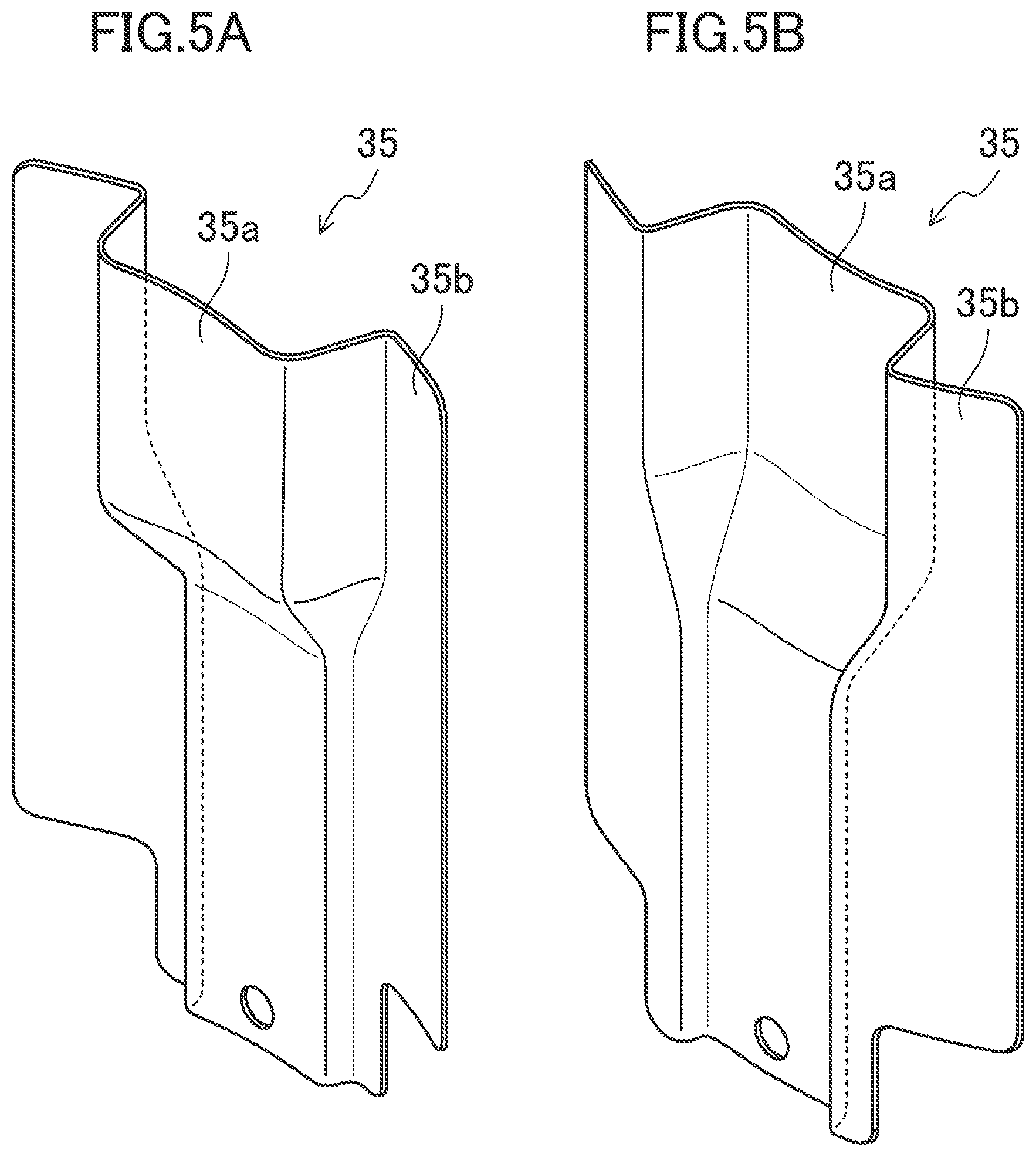
[0010] FIG. 5A is a perspective view illustrating an oil return plate of the compressor shown in FIG. 2 as viewed from the drive shaft, and FIG. 5B is a perspective view illustrating the same as viewed from the casing.
[0011] FIG. 6 is a perspective view illustrating a compression mechanism, housing, and other adjacent components of the compressor shown in FIG. 2 before a second oil return passage is attached.
[0012] FIG. 7 is a perspective view illustrating the compression mechanism, housing, and other adjacent components of the compressor shown in FIG. 2 after the second oil return passage is attached.
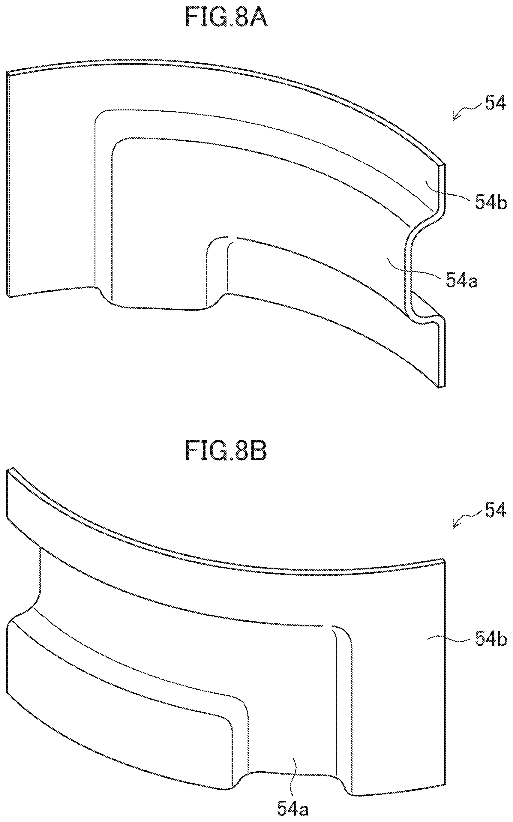
[0013] FIG. 8A is a perspective view illustrating a variation of an internal refrigerant discharge pipe of the compressor shown in FIG. 2 as viewed from the drive shaft, and FIG. 8B is a perspective view illustrating the same as viewed from the casing.
DETAILED DESCRIPTION OF EMBODIMENT(S)
[0014] An embodiment of the present disclosure will be described below with reference to the drawings. The embodiment below is merely an exemplary one in nature, and is not intended to limit the scope, applications, or use of the invention.
Configuration of Refrigeration Apparatus
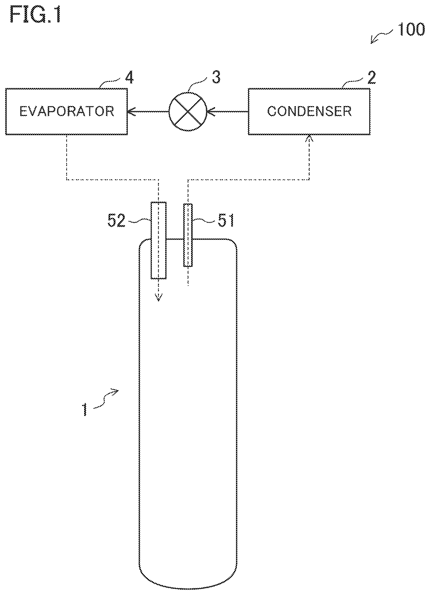
[0015] FIG. 1 is a schematic view illustrating a refrigerant circuit of a refrigeration apparatus (100) including a compressor (1) of the present embodiment.
[0016] As illustrated in FIG. 1, the refrigeration apparatus (100) includes the compressor (1) of the present embodiment, a condenser (2), an expansion mechanism (3), and an evaporator (4). The refrigeration apparatus (100) performs an operation of a refrigeration cycle in which a refrigerant circulates in a refrigerant circuit shown in FIG. 1. Specifically, the refrigerant discharged from a discharge pipe (51) of the compressor (1) is introduced into a suction pipe (52) of the compressor (1) through the condenser (2), the expansion mechanism (3), and the evaporator (4).
Configuration of Compressor
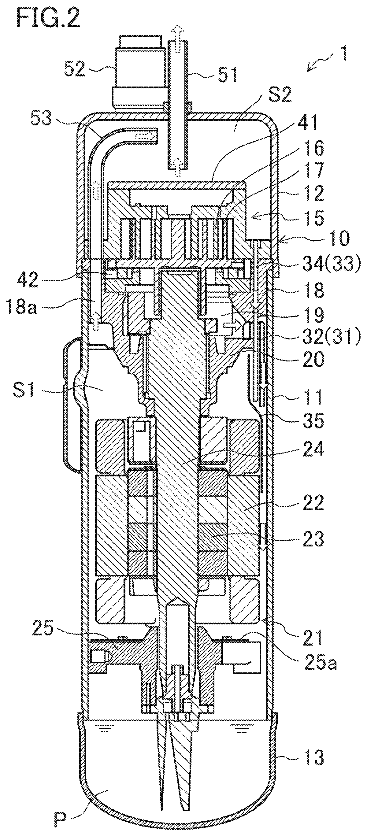
[0017] FIG. 2 is a longitudinal sectional view of the compressor (1) of the present embodiment, and FIG. 3 is a detailed longitudinal sectional view illustrating an upper portion of the compressor (1) shown in FIG. 2. The compressor (1) is a scroll compressor configured to compress a refrigerant when at least one of two scroll parts meshing with each other turns.
[0018] As illustrated in FIGS. 2 and 3, the casing (10) of the compressor (1) includes a substantially cylindrical barrel (11), a bowl-shaped top wall portion (12) hermetically welded to an upper end of the barrel (11), and a bowl-shaped bottom wall portion (13) hermetically welded to a lower end of the barrel (11). The casing (10) is made of a rigid member that is less likely to be deformed and damaged when pressure and temperature inside and outside the casing (10) change. The casing (10) is placed so that the axial direction of the substantially cylindrical barrel (11) extends along the vertical direction. The casing (10) houses, for example, a compression mechanism (15) for compressing the refrigerant, a drive motor (21) disposed below the compression mechanism (15), and a drive shaft (24) disposed to extend vertically in the casing (10). The discharge pipe (51) and the suction pipe (52) for the refrigerant are hermetically joined to the casing (10). The refrigerant is introduced into the casing (10) through the suction pipe (52), compressed in the compression mechanism (15), and then discharged outside the casing (10) through the discharge pipe (51).
[0019] In the compressor (1), a space in the casing (10) between the compression mechanism (15) and the drive motor (21) will be referred to as a space (S1) above the motor (herein referred to as "above-motor space (S1)"), and a space in the casing (10) above the compression mechanism (15) as an oil separation space (S2).
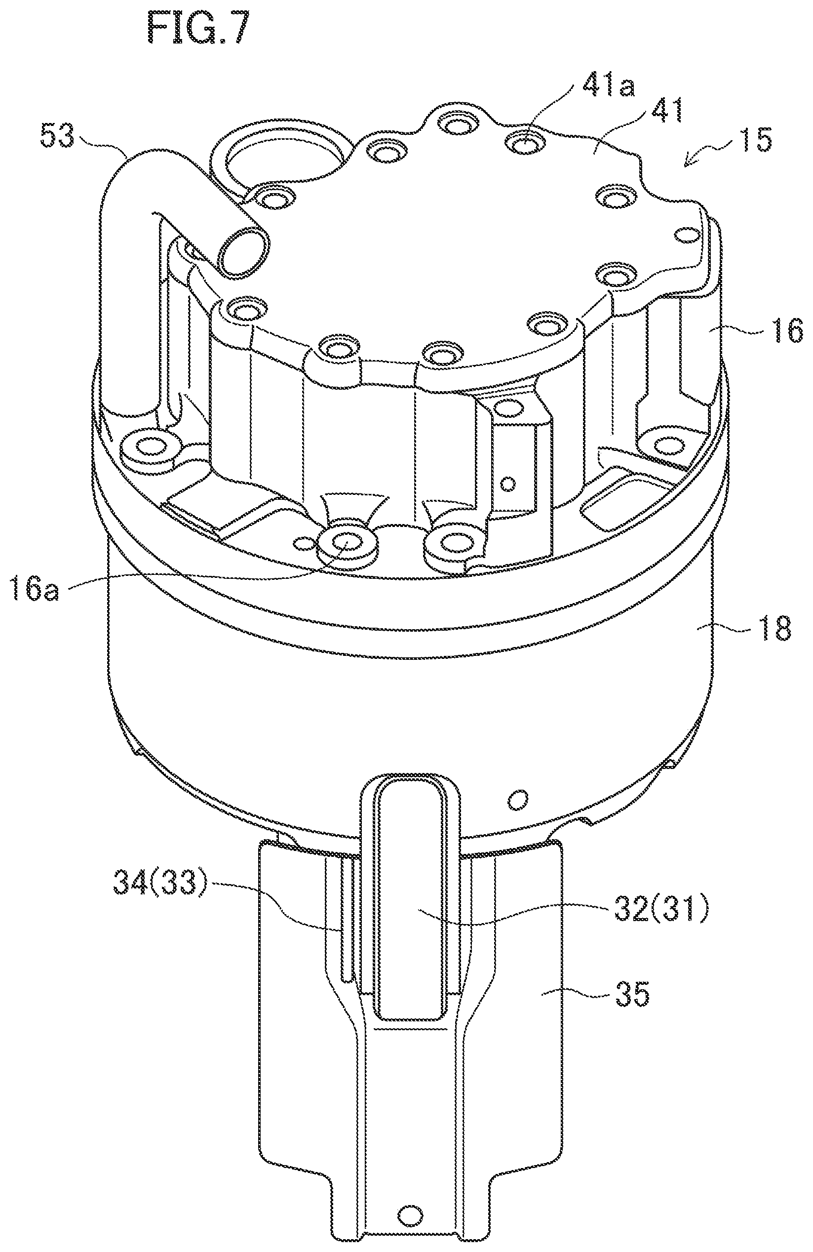
[0020] The compression mechanism (15) includes a fixed scroll part (16) and an orbiting scroll part (17). Each of the fixed scroll part (16) and the orbiting scroll part (17) is configured as an end plate and a spiral lap standing upright on the end plate. The lap of the fixed scroll part (16) and the lap of the orbiting scroll part (17) mesh with each other to form a compression chamber enclosed by the laps and the end plates. A lid (41) is fastened to an upper surface of the fixed scroll part (16) with bolts (41a) (see FIGS. 6 and 7). The fixed scroll part (16) has an internal refrigerant discharge pipe (53) extending to an upper portion of the oil separation space (S2). The internal refrigerant discharge pipe (53) is an L-shaped pipe that extends vertically upward from the fixed scroll part (16), curves in the upper portion of the oil separation space (S2), and extends horizontally along a ceiling of the casing (10).
[0021] A housing (18) is disposed below the compression mechanism (15), and an outer peripheral surface of the housing (18) is joined to an inner wall of the casing (10). The fixed scroll part (16) is placed on the housing (18) by, e.g., bolt fixing. The housing (18) and the fixed scroll part (16) sandwich the orbiting scroll part (17) with an Oldham coupling (42) interposed therebetween. The housing (18) forms a crank chamber (19). The housing (18) has a bearing (20) that supports an upper portion of the drive shaft (24) below the crank chamber (19). The housing (18) is provided with a refrigerant passage (18a) connected to the lower end of the internal refrigerant discharge pipe (53) and communicates with the above-motor space (S1).
[0022] In the present embodiment, the refrigerant introduced into the compression mechanism (15) through the suction pipe (52) is compressed and delivered to the above-motor space (S1) above the motor, passes through the refrigerant passage (18a), the internal refrigerant discharge pipe (53), and the oil separation space (S2), and is discharged outside the casing (10) from the discharge pipe (51) (see open arrows drawn with a broken line in FIGS. 2 and 3).
[0023] The drive motor (21) is, for example, a brushless DC motor, and is disposed below the housing (18). The drive motor (21) includes a stator (22) fixed to the inner wall of the casing (10) and a rotor (23) rotatably housed inside the stator (22) with a slight gap left between the rotor (23) and the stator (22). The rotor (23) is connected to the orbiting scroll part (17) at its center of rotation via the drive shaft (24). A frame (25) is fixed to the barrel (11) of the casing (10) and supports a lower portion of the drive shaft (24) below the drive motor (21). An oil separation plate (25a) is placed on an upper surface of the frame (25) to separate lubricating oil contained in the compressed refrigerant descending from the compression mechanism (15). The separated lubricating oil drops into an oil reservoir (P) at the bottom of the casing (10).
[0024] The drive shaft (24) connects the compression mechanism (15) and the drive motor (21) to each other, and extends vertically in the casing (10). The lower end of the drive shaft (24) is located in the oil reservoir (P). An oil supply passage (not shown) is formed inside the drive shaft (24) to penetrate the drive shaft (24) in the axial direction. When the drive shaft (24) rotates about its axis, an oil pump (e.g., a trochoid pump) disposed at the lower end of the drive shaft (24) causes the lubricating oil stored in the oil reservoir (P) to flow upward in the oil supply passage, thereby lubricating sliding portions (e.g., pin bearings) of the compression mechanism (15). Horizontal oil supply holes (not shown) for supplying the lubricating oil to the sliding portions, such as the bearing (20), are formed inside the drive shaft (24) to be connected to the oil supply passage. The lubricating oil flowing upward in the oil supply passage is supplied to the horizontal oil supply holes to lubricate the sliding portions of the drive shaft (24).
Configuration of Lubricating Oil Recovery Mechanism
[0025] A mechanism for recovering the lubricating oil supplied to lubricate the sliding portions of the compression mechanism (15) and the drive shaft (24) will be described below.
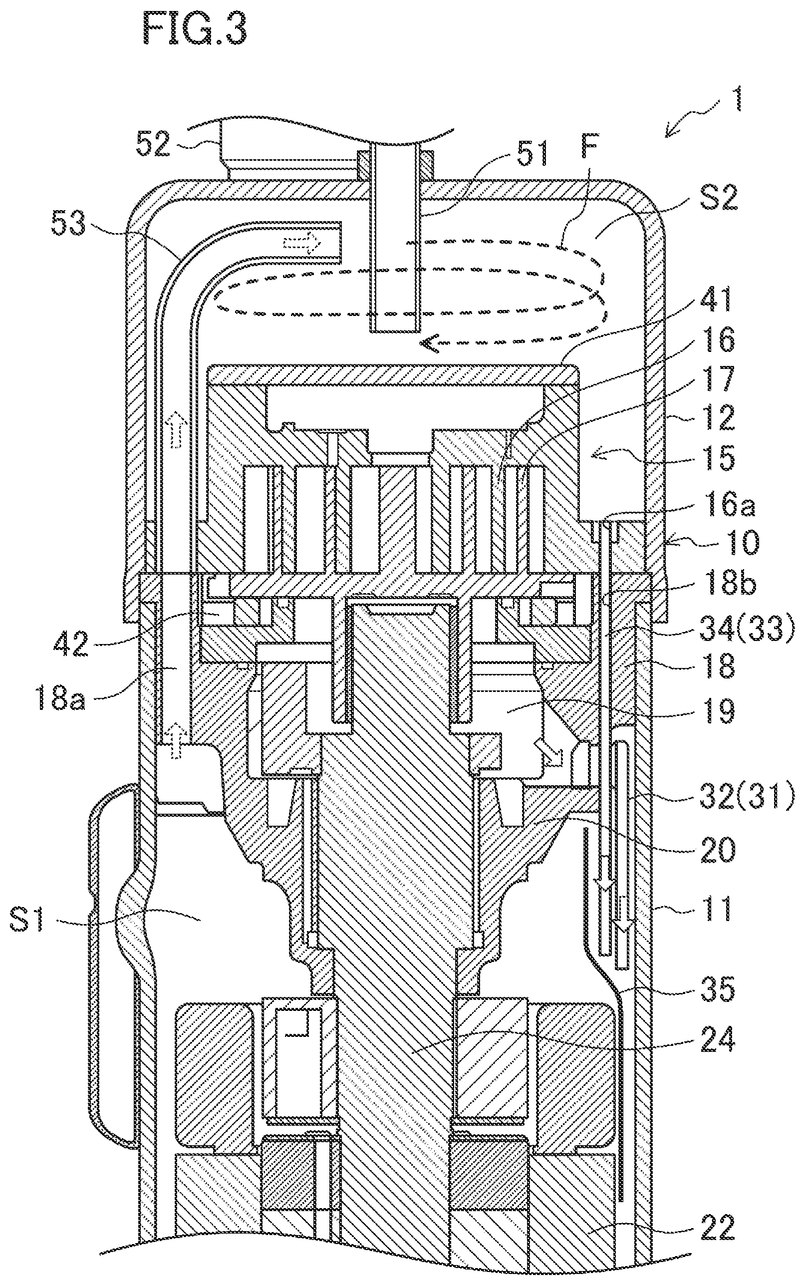
[0026] The lubricating oil used to lubricate the sliding portions of the compression mechanism (15) flows into the crank chamber (19), and is then guided downward through a first oil return passage (31) as illustrated in FIGS. 2 and 3 (see open arrows drawn with a solid line in FIGS. 2 and 3). The first oil return passage (31) is provided with an oil return guide (32) that contracts the flow of the lubricating oil. At least a lower portion of the oil return guide (32) is surrounded by an inner wall surface of the casing (10) and an oil return plate (35) extending downward along the inner wall surface. The lubricating oil delivered from an outlet of the oil return guide (32) descends in the space surrounded by the oil return plate (35) and the inner wall surface of the casing (10), and returns to the oil reservoir (P) at the bottom of the casing (10).
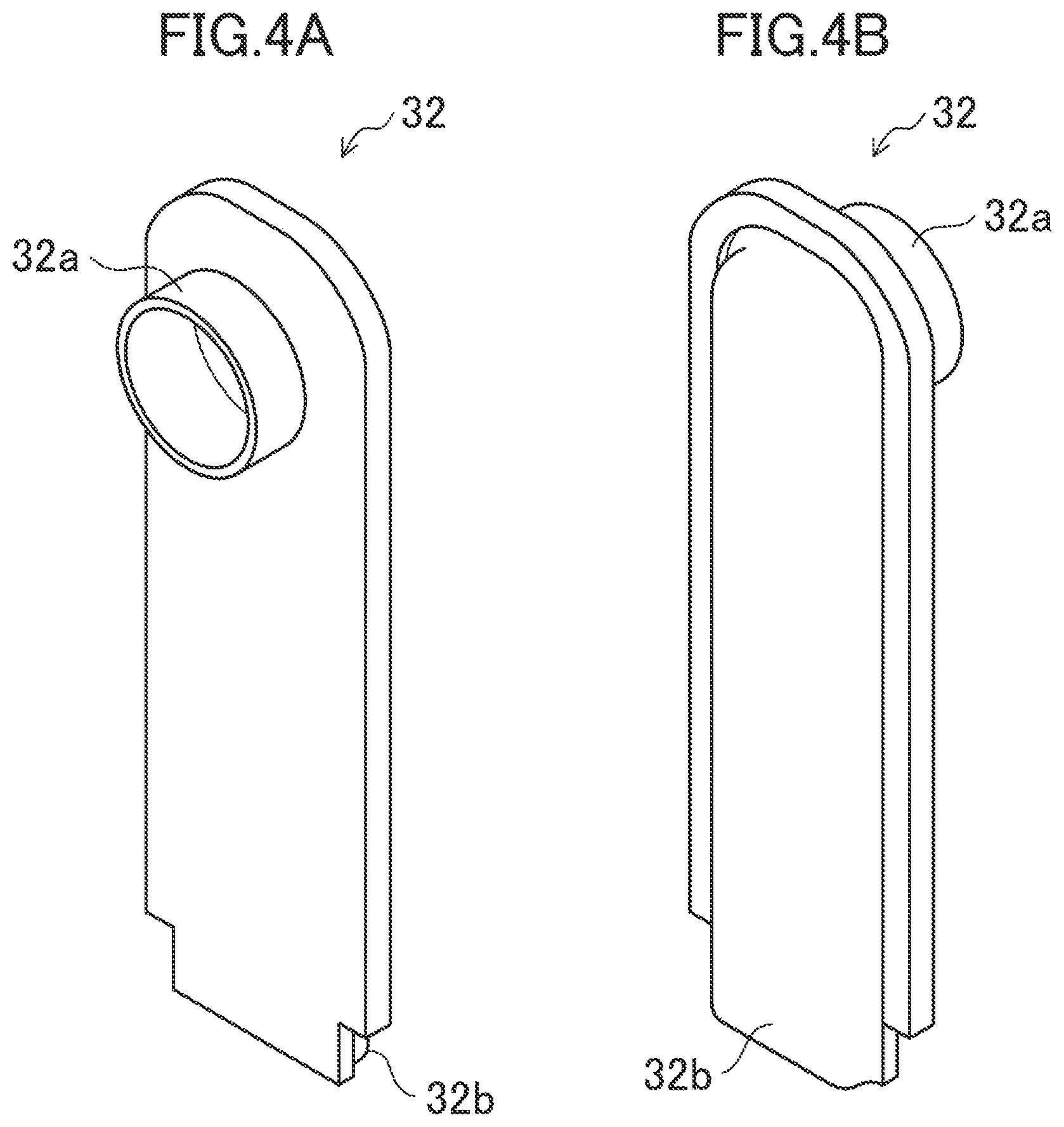
[0027] FIG. 4A is a perspective view illustrating the oil return guide (32) as viewed from the drive shaft (24), and FIG. 4B is a perspective view illustrating the same as viewed from the casing (10). As illustrated in FIGS. 4A and 4B, the oil return guide (32) has a connection hole (32a) connected to the crank chamber (19), and a flow contraction portion (32b) extending downward along the inner wall surface of the casing (10), or of the barrel (11). The flow contraction portion (32b) may be shaped wider in a circumferential direction, than in a radial direction, of the cylindrical casing (10). The flow contraction portion (32b) may have a radial dimension of, for example, about 2 mm to 3 mm, and a circumferential dimension of, for example, about 10 mm.
[0028] FIG. 5A is a perspective view illustrating the oil return plate (35) as viewed from the drive shaft (24), and FIG. 5B is a perspective view illustrating the same as viewed from the casing (10). As illustrated in FIGS. 5A and 5B, the oil return plate (35) includes a surrounding portion (32b) surrounding at least a lower portion (the flow contraction portion (35a)) of the oil return guide (32) from the side of the drive shaft (24), and a fixed portion (35b) fixed to the inner wall surface of the casing (10). The surrounding portion (35a) may be shaped such that a space between the surrounding portion (35a) and the inner wall surface of the casing (10) narrows downward from the vicinity of an outlet of the oil return guide (32). The fixed portion (35b) may have a shape corresponding to the inner wall surface of the casing (10).
[0029] The oil used to lubricate the teeth of the fixed scroll part (16) and the end plate of the orbiting scroll part (17), i.e., a thrust bearing, leaks into the compression chamber during a compression stroke, merges with the lubricating oil originally circulating in the system, and is discharged together with the compressed refrigerant from the compression chamber to the above-motor space (S1). The lubricating oil in the compressed refrigerant is in the form of mist.
[0030] A portion of the lubricating oil contained in the descending compressed refrigerant is separated by the oil separation plate (25a) and returns to the oil reservoir (P) at the bottom of the casing (10) as described above. The rest of the lubricating oil passes through the oil separation space (18a) and the internal refrigerant discharge pipe (53) and is discharged to the refrigerant passage (S2) together with the compressed refrigerant (see the open arrows drawn with a broken line in FIGS. 2 and 3). The compressed refrigerant is discharged to the oil separation space (S2) along the tangential direction of the internal wall surface of the casing (10) (top wall portion (12)), and the discharged compressed refrigerant swirls along the internal wall surface of the top wall portion (12) in the oil separation space (S2) (see a broken line arrow F in FIG. 3). At this time, the lubricating oil contained in the compressed refrigerant is scattered toward the inner wall surface of the top wall portion (12) under the centrifugal force generated by the swirling flow, and collides with the inner wall surface of the top wall portion (12). The lubricating oil that has collided and turned to a liquid film falls along the inner wall surface of the top wall portion (12), and is discharged from an upper oil discharge hole (16a) formed in the fixed scroll part (16) to the above-motor space (S1) through a second oil return passage (33) (see the open arrows drawn with a solid line in FIGS. 2 and 3). The compressed refrigerant from which the lubricating oil has been separated in the oil separation space (S2) is discharged outside the casing (10) through the discharge pipe (51).
[0031] In the present embodiment, a pipe (34) penetrating the fixed scroll part (16) and the housing (18) constitutes the second oil return passage (33). The pipe (34) has an inner diameter of, for example, about 2 mm.
[0032] FIG. 6 is a perspective view illustrating the compression mechanism (15), the housing (18), and other adjacent components before the second oil return passage (33), i.e., the pipe (34), is attached, and FIG. 7 is a perspective view illustrating the same after the second oil return passage (33), i.e., the pipe (34), is attached.
[0033] As illustrated in FIGS. 2, 3, 6, and 7, the fixed scroll part (16) is provided with the upper oil discharge hole (16a) vertically penetrating the fixed scroll part (16), and the housing (18) is provided with a lower oil discharge hole (18b) that vertically penetrates the housing (18) and is connected to the upper oil discharge hole (16a). The pipe (34) serving as the second oil return passage (33) is inserted into the upper oil discharge hole (16a) and the lower oil discharge hole (18b). The lower portion of the pipe (34) protrudes in the above-motor space (S1) below the housing (18), and a lower end of the pipe (34), i.e., an outlet of the second oil return passage (33), is disposed near the outlet of the oil return guide (32). The oil return plate (35) is disposed to surround, together with the inner wall surface of the casing (10), at least the lower portion of the oil return guide (32) and at least the lower portion of the pipe (34). Thus, the lubricating oil delivered from the lower end of the pipe (34), i.e., the outlet of the second oil return passage (33), descends in the space surrounded by the oil return plate (35) and the inner wall surface of the casing (10), and returns to the oil reservoir (P) at the bottom of the casing (10).
[0034] The oil return plate (35) may be shaped such that the space between the oil return plate (35) and the inner wall surface of the casing (10) narrows downward from the vicinity of the outlets of the oil return guide (32) and the pipe (34).
Advantages of Embodiment
[0035] In the compressor (1) of the embodiment described above, the outlet of the second oil return passage (33) for the lubricating oil separated in the oil separation space (S2) in the upper portion of the casing (10) is disposed near the outlet of the oil return guide (32) that contracts the flow of the lubricating oil discharged downward from the crank chamber (19). This configuration can guide the lubricating oil separated in the oil separation space (S2) downward through the second oil return passage (33) under the negative pressure generated not by the contraction of the flow of the refrigerant gas, but by the contraction of the flow of the lubricating oil. Thus, the lubricating oil separated in the oil separation space (S2) does not merge into the flow of the refrigerant gas again, reducing the oil loss more effectively.
[0036] More specifically, the oil that has lubricated the sliding portions (pin bearing, upper main bearing, etc.) of the compression mechanism (15) and the drive shaft (24) once flows into the crank chamber (19), and then returns to the oil reservoir (P) through the oil return guide (32) and the oil return plate (35). When the lubricating oil is guided from the crank chamber (19) to the oil return guide (32), the oil flow is contracted. In particular, a static pressure of a space around the outlet of the oil return guide (32) surrounded by the oil return plate (35) is lower than static pressures of the above-motor space (S1) and the oil separation space (S2). Thus, when the outlet of the second oil return passage (33) is disposed near the outlet of the oil return guide (32), the oil in a liquid state separated in the top space serving as the oil separation space (S2) is discharged into the space surrounded by the oil return plate (35) through the second oil return passage (33), i.e., the pipe (34), and returns to the oil reservoir (P) as it is.
[0037] Specifically, the compressor (1) having the top space serving as the oil separation space (S2) contracts the flow of the oil discharged from the crank chamber (19), and allows a region where the contraction occurs and the oil separation space (S2) to communicate with each other through the second oil return passage (33). Thus, the separated oil can return to the oil reservoir (P) together with the flow of the discharged oil. This can reduce the oil loss of the compressor (1) more effectively.
[0038] As described above, the compressor (1) of the present embodiment can reduce the oil loss more effectively than a known compressor in which liquid oil separated in the top space is discharged into the discharged refrigerant gas. The top space serving as the oil separation space (S2) basically separates the oil as effectively as a known oil separator that is independently provided. Thus, the compressor (1) can be provided without such an oil separator, reducing the cost and size of an air-conditioning system such as a refrigeration apparatus.
[0039] When the compressor (1) of the present embodiment includes the pipe (34) passing through the housing (18) as the second oil return passage (33), the structure of the second oil return passage (33) can be simplified.
[0040] The compressor (1) of the present embodiment further includes an oil return plate (35) disposed to surround, together with the inner wall surface of the casing (10), at least a lower portion of the second oil return passage (33) and at least a lower portion of the oil return guide (32). This configuration can keep the lubricating oil delivered from the outlets of the second oil return passage (33) and the oil return guide (32) from scattering. In this case, when a space surrounded by the oil return plate (35) and the inner wall surface of the casing (10) narrows downward from the vicinity of the outlets of the second oil return passage (33) and the oil return guide (32), the lubricating oil flows faster as it goes downward. This can efficiently guide the lubricating oil downward.
Other Embodiments
[0041] In the above embodiment, the compressor (1) having the configuration shown in
[0042] FIG. 2 has been described. In the present disclosure, however, the compressor is not limited to have such a configuration as long as the top space is used as the oil separation space and the lubricating oil is stored in the bottom. For example, the shape of the oil return guide (32) shown in FIGS. 4A and 4B and the shape of the oil return plate (35) shown in FIGS. 5A and 5B are merely examples, and the oil return guide (32) and the oil return plate (35) are not limited to have these shapes.
[0043] In the above embodiment, the whole second oil return passage (33) is formed of the pipe (34). However, the upper oil discharge hole (16a) and the lower oil discharge hole (18b) may be used as part of the second oil return passage (33) as they are. Alternatively, the second oil return passage (33) having no upper oil discharge hole (16a) may be formed without providing the fixed scroll part (16) on the lower oil discharge hole (18b) of the housing (18).
[0044] Instead of the oil return plate (35) disposed in the above embodiment, for example, the oil return guide (32) and the pipe (34) may further extend downward to eliminate the need of the oil return plate (35).
[0045] In place of a circular tube extending in an L-shape arranged as the internal refrigerant discharge pipe (53) of the above embodiment, for example, a sheet metal member (54) as shown in FIGS. 8A and 8B may be attached to the inner wall of the top wall portion (12) to serve as the internal refrigerant discharge pipe. FIG. 8A is a perspective view illustrating the sheet metal member (54) as viewed from the drive shaft, and FIG. 8B is a perspective view illustrating the same as viewed from the casing. As illustrated in FIGS. 8A and 8B, the sheet metal member (54) has a pipe wall portion (54a) that forms a conduit serving as the internal refrigerant discharge pipe between the pipe wall portion (54a) and the internal wall of the top wall portion (12), and a fixed portion (54b) fixed to the internal wall surface of the top wall portion (12). The pipe wall portion (54a) may extend vertically upward from the fixed scroll part (16), curve in an upper portion of the oil separation space (S2), and extend horizontally. The fixed portion (54b) may have a shape corresponding to the inner wall surface of the top wall portion (12).
[0046] While the embodiments have been described above, it will be understood that various changes in form and details can be made without departing from the spirit and scope of the claims. The embodiment and other embodiments may be combined and replaced with each other without deteriorating intended functions of the present disclosure. The expressions of "first" and "second" described above are used to distinguish the terms to which these expressions are given, and do not limit the number and order of the terms.
[0047] The present disclosure is useful for a compressor and a refrigeration apparatus.
* * * * *
D00000
D00001
D00002
D00003
D00004
D00005
D00006
D00007
D00008
XML
uspto.report is an independent third-party trademark research tool that is not affiliated, endorsed, or sponsored by the United States Patent and Trademark Office (USPTO) or any other governmental organization. The information provided by uspto.report is based on publicly available data at the time of writing and is intended for informational purposes only.
While we strive to provide accurate and up-to-date information, we do not guarantee the accuracy, completeness, reliability, or suitability of the information displayed on this site. The use of this site is at your own risk. Any reliance you place on such information is therefore strictly at your own risk.
All official trademark data, including owner information, should be verified by visiting the official USPTO website at www.uspto.gov. This site is not intended to replace professional legal advice and should not be used as a substitute for consulting with a legal professional who is knowledgeable about trademark law.