Sealed Intake Air System
Niakan; Shahriar Nick ; et al.
U.S. patent application number 17/571156 was filed with the patent office on 2022-04-28 for sealed intake air system. This patent application is currently assigned to Advanced Flow Engineering, Inc.. The applicant listed for this patent is Advanced Flow Engineering, Inc.. Invention is credited to George R. Chiang, Shahriar Nick Niakan.
| Application Number | 20220128021 17/571156 |
| Document ID | / |
| Family ID | 1000006075331 |
| Filed Date | 2022-04-28 |


| United States Patent Application | 20220128021 |
| Kind Code | A1 |
| Niakan; Shahriar Nick ; et al. | April 28, 2022 |
SEALED INTAKE AIR SYSTEM
Abstract
A sealed intake air system incorporates a positive connection seal interface between the air filter and the airbox with captive fasteners to provide a positive connection between the air filter and the one-piece airbox.
| Inventors: | Niakan; Shahriar Nick; (Corona, CA) ; Chiang; George R.; (Corona, CA) | ||||||||||
| Applicant: |
|
||||||||||
|---|---|---|---|---|---|---|---|---|---|---|---|
| Assignee: | Advanced Flow Engineering,
Inc. Corona CA |
||||||||||
| Family ID: | 1000006075331 | ||||||||||
| Appl. No.: | 17/571156 | ||||||||||
| Filed: | January 7, 2022 |
Related U.S. Patent Documents
| Application Number | Filing Date | Patent Number | ||
|---|---|---|---|---|
| 16510357 | Jul 12, 2019 | 11236713 | ||
| 17571156 | ||||
| 62697219 | Jul 12, 2018 | |||
| Current U.S. Class: | 1/1 |
| Current CPC Class: | F02M 35/0209 20130101; B01D 2279/60 20130101; B01D 2265/02 20130101; F02M 35/02416 20130101; F02M 35/0204 20130101; B01D 46/521 20130101; B01D 46/0012 20130101; B01D 46/0005 20130101; F02M 35/0245 20130101; F02M 35/0203 20130101; B01D 2277/20 20130101; F02M 35/10321 20130101 |
| International Class: | F02M 35/024 20060101 F02M035/024; F02M 35/02 20060101 F02M035/02; B01D 46/52 20060101 B01D046/52; B01D 46/00 20060101 B01D046/00 |
Claims
1. An intake air system comprising: a one-piece enclosed housing airbox having an intake opening and an opposite air filter interface, the air filter interface having a plurality of inserts molded into filter interface of the airbox; and an air filter with a filter flange configured to engage the air filter interface in the airbox and having filter media secured between a rigid base flange and a top; wherein the air filer interface apposes and engages the air filter flange.
2. The sealed intake air system of claim 1 further comprising: a bellows coupler operably connected to the rigid base flange.
3. The sealed intake air system of claim 2 further comprising: an intake tube operably connected to the bellows coupler to conduct filtered air to an engine air intake.
4. The sealed intake air system of claim 1 wherein the one-piece airbox includes a plurality of intake openings.
5. The sealed intake air system of claim 1 wherein the rigid air filter base and the top each have a surface angled to conform to the filter media.
6. The sealed intake air system of claim 1 further comprising: A straight coupler between the bellows coupler and the rigid air filter base.
Description
[0001] This application is a continuation of U.S. application Ser. No. 16/510,357, filed Jul, 12, 2019, which claims priority U.S. Provisional Application 62/697,219, filed Jul. 12, 2018.
FIELD OF THE INVENTIONS
[0002] The inventions described below relate to the field of sealed air intake systems for internal combustion engines.
BACKGROUND OF THE INVENTIONS
[0003] Conventional air filter systems often employ complicated geometry to trap the air filter element in the air flow path and they often require a host of other parts to keep the air filter in place and to isolate the air filter from power-robbing engine heat.
SUMMARY
[0004] The sealed intake air system incorporates a positive connection seal interface between the air filter and the airbox with captive fasteners to provide a positive connection between the air filter and the one-piece airbox. The air filter is formed around a rigid, molded base with a flange that engages a mating surface in the airbox.
BRIEF DESCRIPTION OF THE DRAWINGS
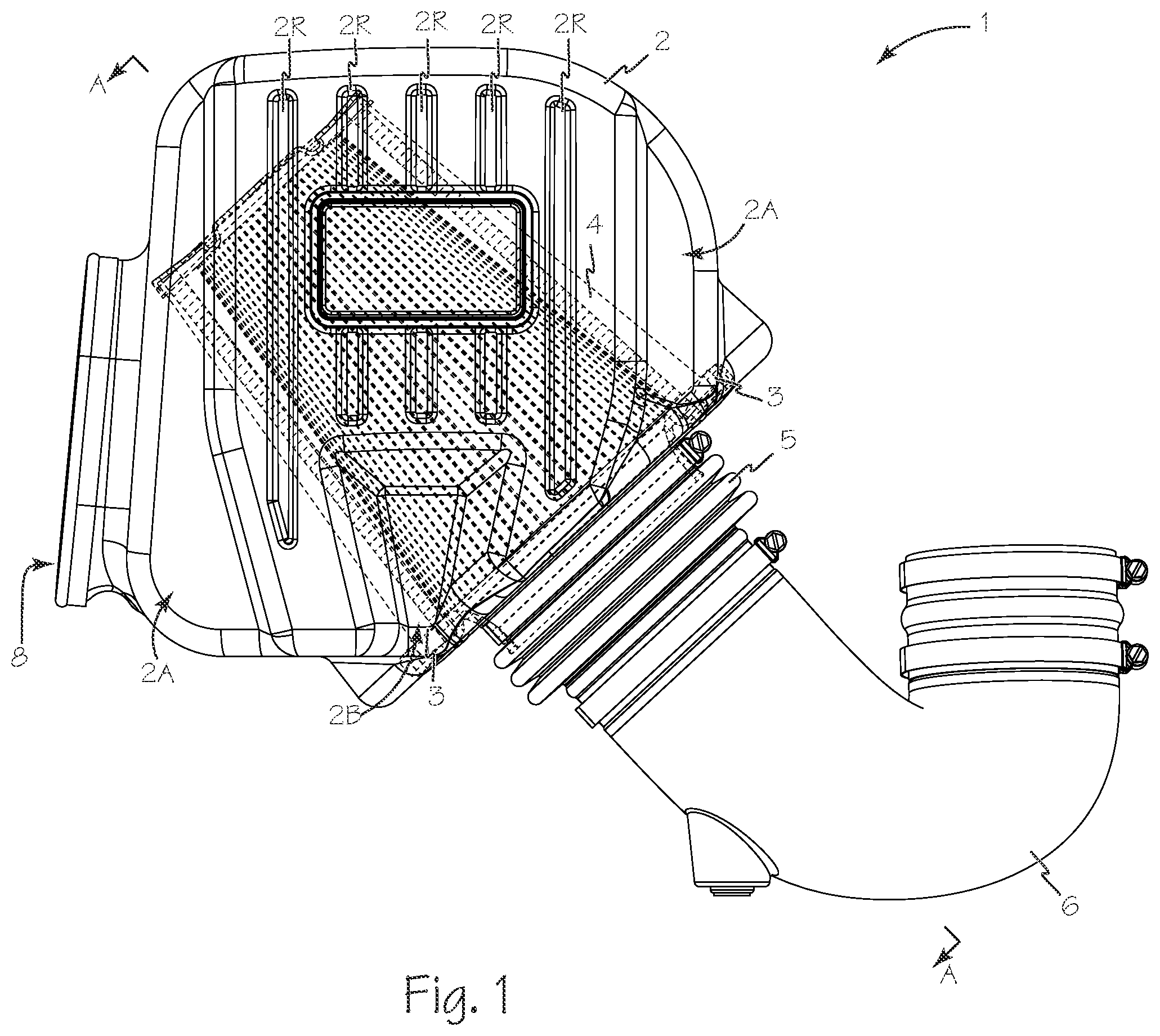
[0005] FIG. 1 is a top view of a sealed intake air system.
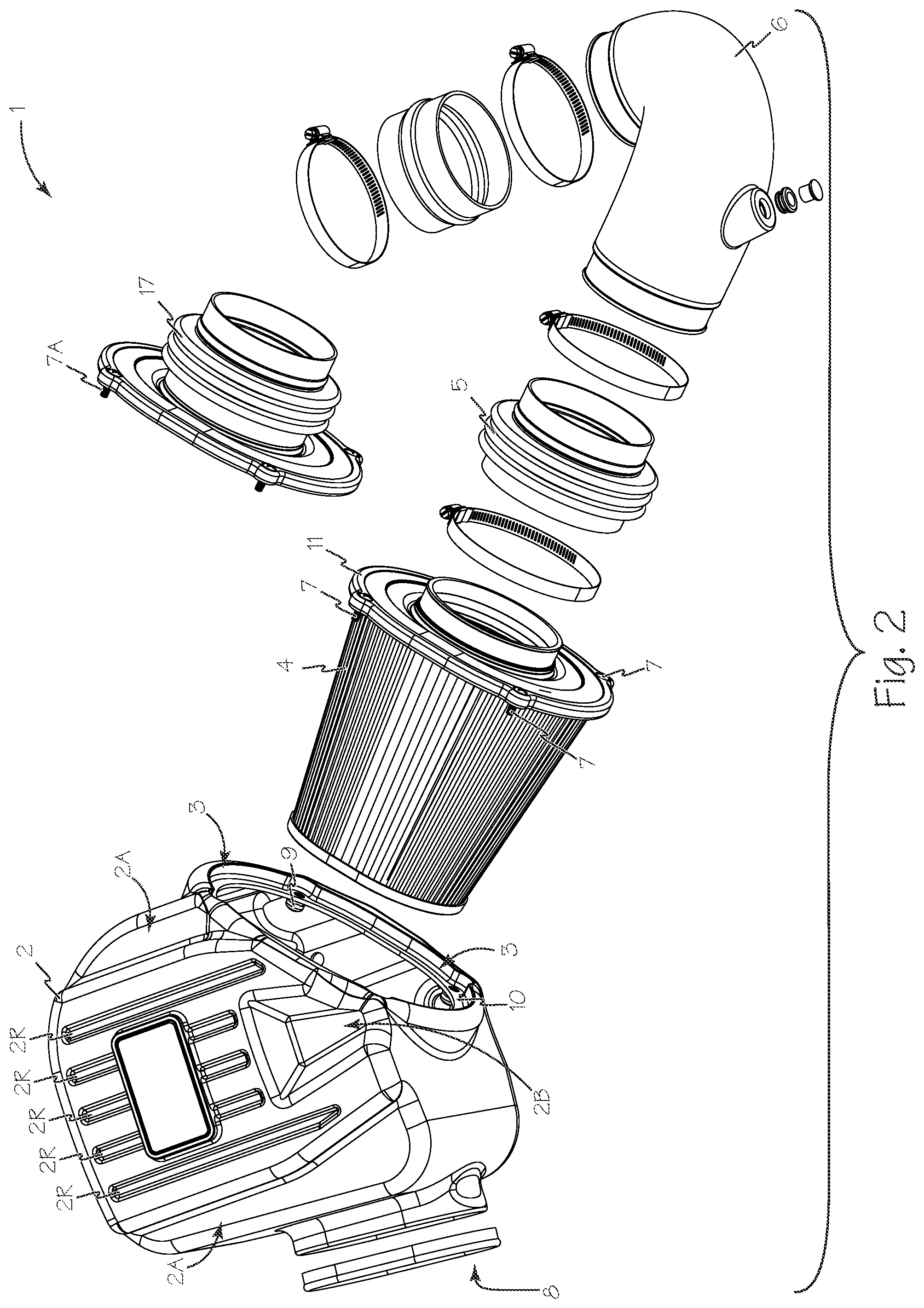
[0006] FIG. 2 is an exploded view of the sealed intake air system of FIG. 1.
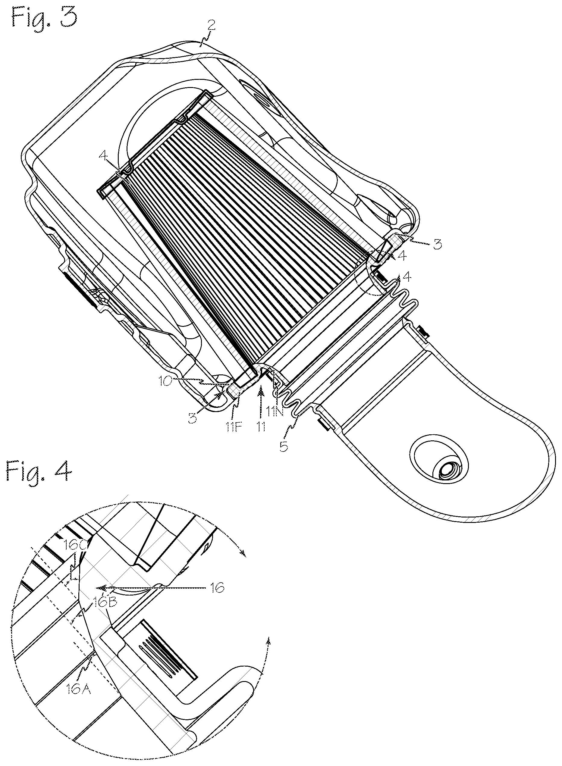
[0007] FIG. 3 is a cross-section view of the sealed intake air system of FIG. 1 taken along A-A.
[0008] FIG. 4 is a close up of a portion of the sealed intake air system view of FIG. 3 taken along B-B
[0009] FIG. 5 is a perspective view of the air filter used in the sealed intake air system of FIG. 1.
[0010] FIG. 6 is an exploded view of the air filter of FIG. 5.
DETAILED DESCRIPTION OF THE INVENTIONS
[0011] The sealed air intake system 1 is illustrated in FIGS. 1 and 2. The sealed air intake system 1 incorporates a one-piece airbox 2 with a filter interface 3 for achieving a secure seal with the air filter 4. A bellows coupler 5 is generally connected between the air filter 4 and intake tube 6. Alternately, there may be one or more elements such as a straight coupler between the air filter base 11 and the bellows coupler 5. Intake tube 6 conducts clean filtered air to the air input for any suitable internal combustion engine. The bellows coupler 5 is generally formed of injected silicone and any other suitable material may be used such as polyurethane, plastisol, etc. Airbox 2 incorporates a unique 5-rib design with ribs 2R that make the airbox readily identifiable. In addition there may be included additional optional contoured features such as features 2A that are generally parallel to the outer ribs and contoured feature 2B that adjoins the three middle ribs.
[0012] As illustrated in FIG. 2, air filter 4 is secured to airbox 2 at interface 3 using a suitable number of captive connectors 7 such as screws, Dzus.RTM. fasteners, studs and nuts, plastic retaining clips, etc. Alternatively, the air filter may be secured to the airbox using double sided tape, adhesives or hook and loop fasteners. The airbox is preferably a one-piece sealed housing with at least one intake such as opening 8 that can be trimmed to adjust the size of the opening 8. Additional optional openings in the airbox will allow for extra air flow to reach the air filter 4.
[0013] Optionally, the air filter base 11 may be formed together with the bellows coupler 5 as integrated filter base 17 illustrated in FIG. 2. Integrated filter base 17 may be formed of any suitable compliant material. When integrated filter base 17 is used, connectors 7A should have shoulders to control compression of the filter flange.
[0014] Any suitable inserts 9 may be molded into the airbox to engage the captive fasteners 7 from the filter providing a positive connection of the filter to the airbox without the need for any additional hardware. The inserts can be made of brass or any other suitable materials and can be threaded or non-threaded (press fit, insert clips, etc. may be used). The inserts may or may not be used depending upon the attachment type selected.
[0015] Interface 3 is illustrated in FIG. 3. Surface 10 of the airbox apposes and engages air filter flange 11F. Optionally, one or more sealing elements 12, shown in FIG. 6, such as rubber or silicon o-rings or any other suitable seal is compressed between surface 10 and filter flange 11F and the compression is maintained by the engagement of the captive connectors 7 securing the air filter to the airbox. FIG. 4 illustrates a close-up of a portion of the air filter base 11 showing the integrated 3-angle throat or 3-angle velocity stack 16 with angles 16A, 16B and 16C in the base neck 11N.
[0016] Air filter 4 is illustrated in FIGS. 5 and 6. The air filter flange has an oval shape but is not limited to this geometry (it can be made to be any other shape). The plastic filter base 11 has an integrated 3-angle throat or 3-angle velocity stack 16 with angles 16A, 16B and 16C that allows smooth and even entry of air at high velocities; alternate configurations include a single angle or multiple angles, a radius of circular or elliptical form, or a combination of angles and radii. Polyurethane 13 is used to attach the filter media 14 to the plastic filter flange 11 and top 15 but other types of adhesives or mechanical bonding can be used (i.e., super glue, rtv, rubber cement, resin, epoxy, etc.). The air filter base 11 and top 15 are made out of ABS but other materials can be used (including but not limited to Polyurethane, Polyethylene, aluminum, etc.). Air filter flange 11F and air filter top 15 have angled interior surfaces 11B and 15B respectively that are angled to conform to the angle of the air filter media 14. The angled surfaces 11B and 15B minimize the thickness of polyurethane seals 13 which reduces the overall weight of the air intake system.
[0017] While the preferred embodiments of the devices and methods have been described in reference to the environment in which they were developed, they are merely illustrative of the principles of the inventions. The elements of the various embodiments may be incorporated into each of the other species to obtain the benefits of those elements in combination with such other species, and the various beneficial features may be employed in embodiments alone or in combination with each other. Other embodiments and configurations may be devised without departing from the spirit of the inventions and the scope of the appended claims.
* * * * *
D00000
D00001
D00002
D00003
D00004
D00005
XML
uspto.report is an independent third-party trademark research tool that is not affiliated, endorsed, or sponsored by the United States Patent and Trademark Office (USPTO) or any other governmental organization. The information provided by uspto.report is based on publicly available data at the time of writing and is intended for informational purposes only.
While we strive to provide accurate and up-to-date information, we do not guarantee the accuracy, completeness, reliability, or suitability of the information displayed on this site. The use of this site is at your own risk. Any reliance you place on such information is therefore strictly at your own risk.
All official trademark data, including owner information, should be verified by visiting the official USPTO website at www.uspto.gov. This site is not intended to replace professional legal advice and should not be used as a substitute for consulting with a legal professional who is knowledgeable about trademark law.