Service Tube Assembly For A Gas Turbine Engine
LEFEBVRE; Guy ; et al.
U.S. patent application number 17/081055 was filed with the patent office on 2022-04-28 for service tube assembly for a gas turbine engine. The applicant listed for this patent is PRATT & WHITNEY CANADA CORP.. Invention is credited to Guy LEFEBVRE, Remy SYNNOTT.
| Application Number | 20220127974 17/081055 |
| Document ID | / |
| Family ID | 1000005209687 |
| Filed Date | 2022-04-28 |


| United States Patent Application | 20220127974 |
| Kind Code | A1 |
| LEFEBVRE; Guy ; et al. | April 28, 2022 |
SERVICE TUBE ASSEMBLY FOR A GAS TURBINE ENGINE
Abstract
A tube assembly according to an exemplary aspect of the present disclosure includes, among other things, an adjustable joint having a flange axially movable along an end fitting having a male/female connection with a mating part. The flange is threadably engaged with the end fitting to provide for the adjustment of the position of the flange along the end fitting. The adjustable joint accommodates thermal effects and tolerance stack-up in a male/female connection.
| Inventors: | LEFEBVRE; Guy; (St-Bruno-de-Montarville, CA) ; SYNNOTT; Remy; (St-Jean-sur-Richelieu, CA) | ||||||||||
| Applicant: |
|
||||||||||
|---|---|---|---|---|---|---|---|---|---|---|---|
| Family ID: | 1000005209687 | ||||||||||
| Appl. No.: | 17/081055 | ||||||||||
| Filed: | October 27, 2020 |
| Current U.S. Class: | 1/1 |
| Current CPC Class: | F05D 2260/98 20130101; F02C 7/20 20130101; F05D 2260/60 20130101; F01D 25/18 20130101 |
| International Class: | F01D 25/18 20060101 F01D025/18; F02C 7/20 20060101 F02C007/20 |
Claims
1. A service tube assembly for a gas turbine engine, comprising: a first service tube having a first fitting and a first abutment surface; a second service tube having a second fitting and a second abutment surface, the second fitting engaged in a male/female connection with the first fitting, the second abutment surface threadably engaged with a threaded portion of the second fitting to adjustably position the second abutment surface along the second fitting at a location where the second abutment surface abuts the first abutment surface of the first service tube; and a fastener clamping the first and second abutment surfaces together.
2. The service tube assembly according to claim 1, wherein the first abutment surface is part of a first flange extending from the first fitting, wherein the second abutment surface is part of a second flange threadably engaged with the threaded portion of the second fitting, and wherein the fastener comprises a pair of fasteners extending through registering holes defined in the first and second flanges.
3. The service tube assembly according to claim 2, wherein the pair or fasteners includes first and second sets of bolts and nuts.
4. The service tube assembly according to claim 1, wherein the first abutment surface is provided at a distal end of the first fitting, wherein the second abutment surface is provided at an end of a nut threadably engaged with the threaded portion of the second fitting, and wherein the fastener has a tubular body having an inner shoulder engaged behind a corresponding outer shoulder projecting from the nut, the tubular body having internal threads threadably engageable with external threads on the first fitting.
5. The service tube assembly according to claim 2, wherein the threaded portion includes external threads provided on an outer surface of the second fitting, and wherein the second flange has internal threads threadably engaged with the external threads.
6. The service tube assembly according to claim 5, wherein the second fitting has a male portion projecting beyond the threaded portion for mating engagement within a female portion of the first fitting.
7. The service tube assembly according to claim 6, wherein the male portion carries a seal for sealing engagement with an inner surface of the first fitting.
8. The service tube assembly according to claim 7, wherein the seal includes axially spaced-apart O-rings disposed in corresponding grooves defined on the male portion.
9. The service tube assembly according to claim 6, wherein the first and second abutment surfaces surround the male portion.
10. A service tube assembly for a gas turbine engine, comprising: an engine component having a first fitting and an abutment surface; a service tube fluidly connected to the engine component, the service tube having a second fitting at one end thereof, the second fitting engaged in a male/female connection with the first fitting of the engine component, the second fitting having a threaded portion and a second abutment surface threadably engaged with the threaded portion for adjusting a position of the second abutment surface along the second fitting so as to bring the second abutment surface in abutment against the first abutment surface; and a fastener clamping the first and second abutment surfaces together.
11. The service tube assembly according to claim 10, wherein the engine component is another service tube.
12. The service tube assembly according to claim 11, wherein the first abutment surface is part of a first flange extending from the first fitting, wherein the second abutment surface is part of a second flange threadably engaged with the threaded portion of the second fitting, and wherein the fastener comprises at plurality of fasteners extending through respective registering holes defined in the first and second flanges.
13. The service tube assembly according to claim 10, wherein the threaded portion includes external threads provided on an outer surface of the second fitting, and wherein the second flange has internal threads threadably engaged with the external threads.
14. The service tube assembly according to claim 10, wherein the second fitting has a male portion projecting beyond the threaded portion for mating engagement within a female portion of the first fitting.
15. The service tube assembly according to claim 14, wherein spaced-apart O-rings are provided between the male portion and the female portion.
16. A service tube assembly for a gas turbine engine, comprising: a first service tube having a first fitting at one end thereof, the first fitting having a first flange; a second service tube having a second fitting at one end thereof, the second fitting engageable in a male/female connection with the first fitting, the second fitting having a threaded portion and a second flange threadably engaged with the threaded portion to adjust a position of the second flange along the second fitting, the second flange movable to a position in which the second flange abuts the first flange; and fasteners engageable in registering holes defined in the first and second flanges for clamping the first and second flanges together.
17. The service tube assembly according to claim 16, wherein the threaded portion has external threads provided on an outer surface of the second fitting, and wherein the second flange has internal threads threadably engaged with the external threads.
18. The service tube assembly according to claim 17, wherein the second fitting has a male portion projecting beyond the threaded portion for mating engagement within the first fitting.
19. The service tube assembly according to claim 18, wherein the male portion carries a seal for sealing engagement with an inner surface of the first fitting.
20. The service tube assembly according to claim 19, wherein the seal includes axially spaced-apart O-ring seals.
Description
TECHNICAL FIELD
[0001] The application relates generally to gas turbine engines and, more particularly, to service tube assemblies.
BACKGROUND OF THE ART
[0002] Service tubes fluidly couple different portions of a gas turbine engine or couple portions of the engine to other associated components, such as aircraft components. The service tubes can, for instance, supply oil or an oil/air mixture to and/or from the engine and between the different portions of the engine. Due to tolerance stack-up, the tube ends may not always perfectly coincide with their points of attachment on the engine. Such tolerance stack-up may result in undesirable stresses in the tubes at cold assembly.
[0003] Tube assembly alternatives are, thus, desirable.
SUMMARY
[0004] In one aspect, there is provided a service tube assembly for a gas turbine engine, comprising: a first service tube having a first fitting and a first abutment surface; a second service tube having a second fitting and a second abutment surface, the second fitting engaged in a male/female connection with the first fitting, the second abutment surface threadably engaged with a threaded portion of the second fitting to adjustably position the second abutment surface along the second fitting at a location where the second abutment surface abuts the first abutment surface of the first service tube; and a fastener clamping the first and second abutment surfaces together.
[0005] In another aspect, there is provided a service tube assembly for a gas turbine engine, comprising: an engine component having a first fitting and an abutment surface; a service tube fluidly connected to the engine component, the service tube having a second fitting at one end thereof, the second fitting engaged in a male/female connection with the first fitting of the engine component, the second fitting having a threaded portion and a second abutment surface threadably engaged with the threaded portion for adjusting a position of the second abutment surface along the second fitting so as to bring the second abutment surface in abutment against the first abutment surface; and a fastener clamping the first and second abutment surfaces together.
[0006] In a further aspect, there is provided a method for installing a fluid line between first and second ports of a gas turbine engine, the method comprising: pre-assembling first and second tubes in an adjustable male/female connection so as to form an adjustable joint therebetween, connecting an opposed end of the first tube to the first port; connecting an opposed end of the second tube to the second port, adjusting a position of an adjustable flange on the second tube to bring the adjustable flange in abutment against a corresponding flange on the first tube at the adjustable male/female connection, wherein adjusting the position of the adjustable flange comprises threading or unthreading the adjustable flange on a threaded portion of the second tube; and clamping the first and second flanges together to secure the male/female connection.
[0007] In a still further aspect, a service tube assembly for a gas turbine engine, comprising: a first service tube having a first fitting at one end thereof, the first fitting having a first flange; a second service tube having a second fitting at one end thereof, the second fitting engageable in a male/female connection with the first fitting, the second fitting having a threaded portion and a second flange threadably engaged with the threaded portion to adjust a position of the second flange along the second fitting, the second flange movable to a position in which the second flange abuts the first flange; and fasteners engageable in registering holes defined in the first and second flanges for clamping the first and second flanges together.
DESCRIPTION OF THE DRAWINGS
[0008] Reference is now made to the accompanying figures in which:
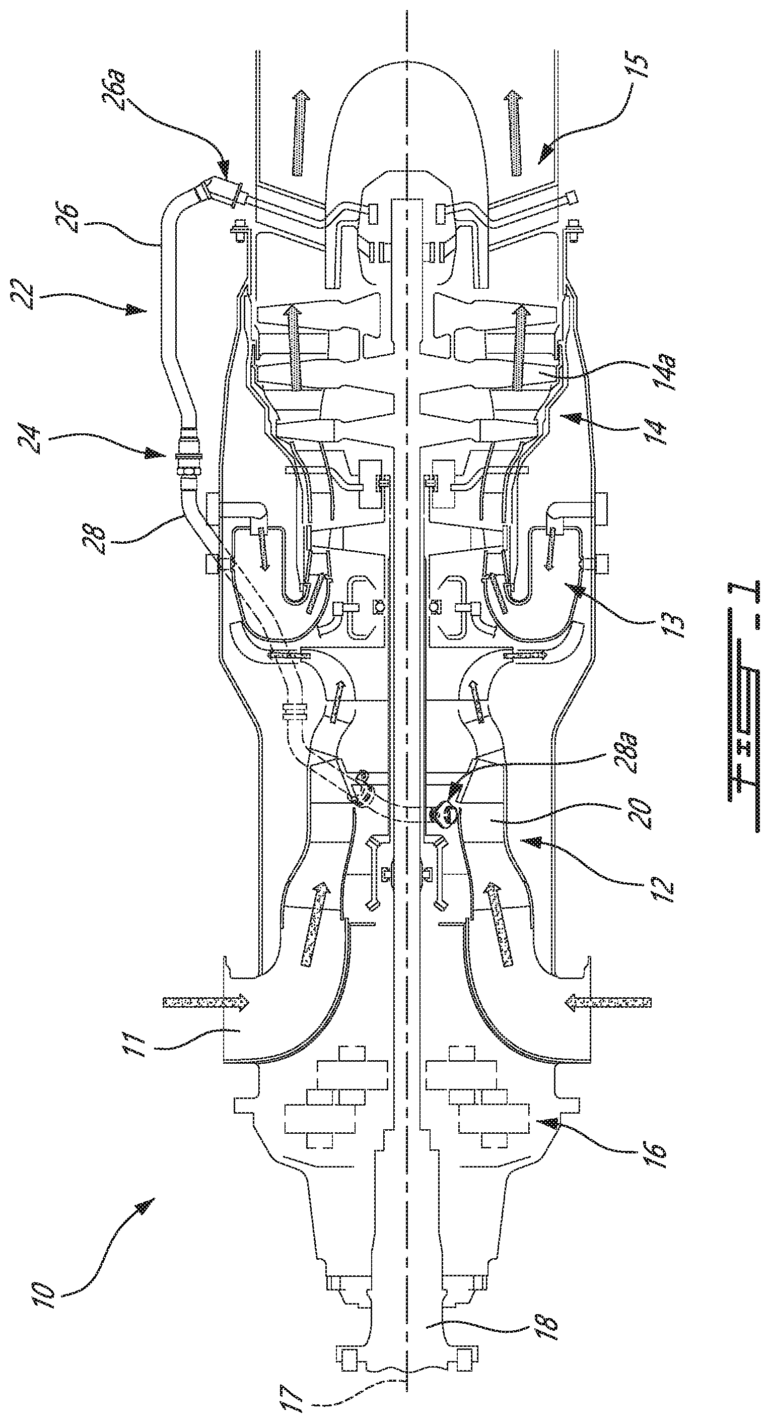
[0009] FIG. 1 is a schematic cross-section view of a gas turbine engine having a tube assembly with an adjustable joint between a compressor and an exhaust section of the engine;
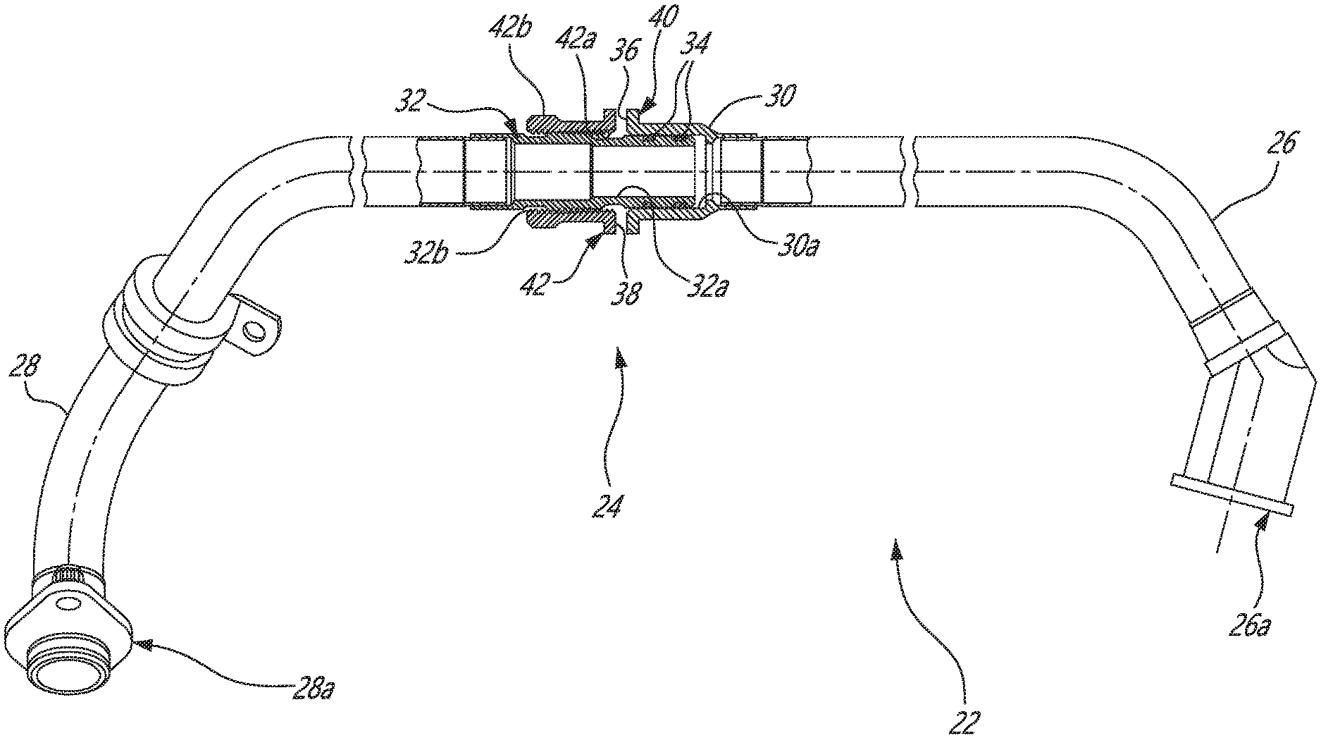
[0010] FIG. 2 is a schematic cross-section view of the tube assembly illustrating the adjustable joint in a partially engaged state;
[0011] FIGS. 3a and 3b are isometric views of the adjustable joint respectively shown in a partially and a fully assembled state;
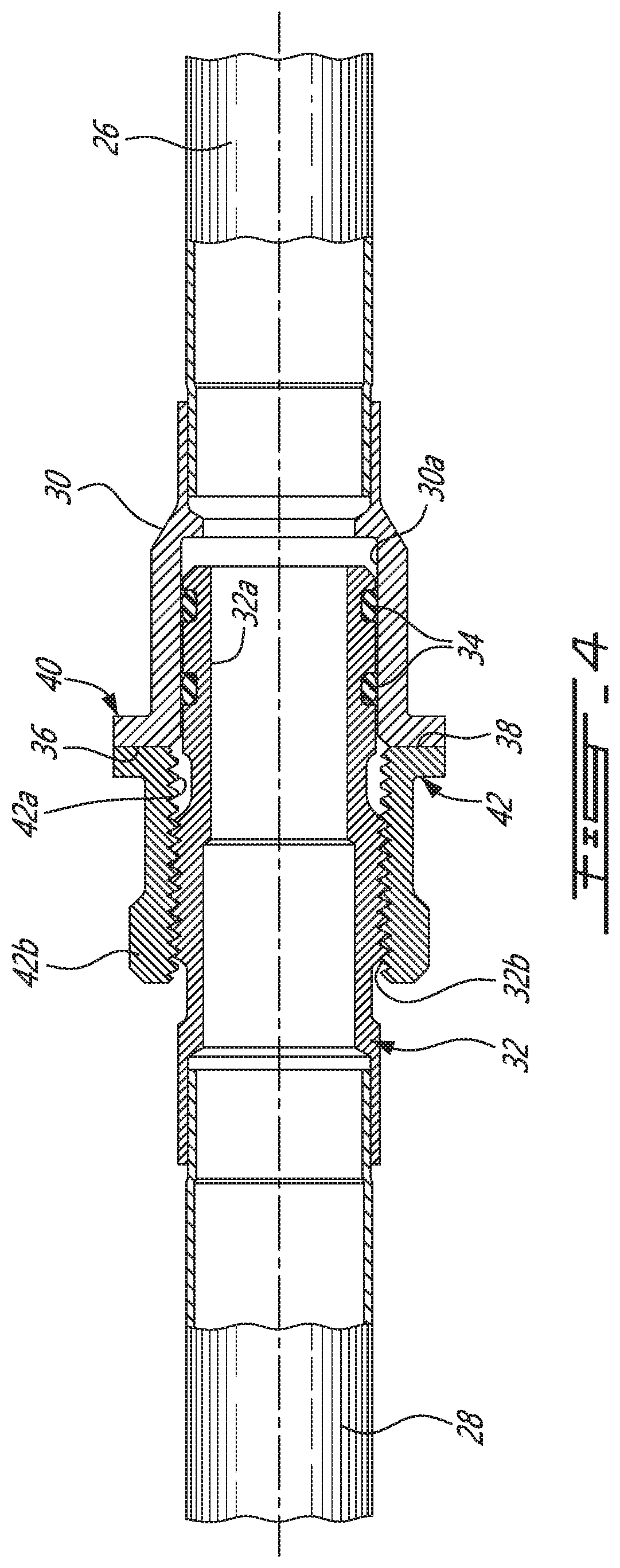
[0012] FIG. 4 is an enlarged cross-section view illustrating details of the adjustable joint;
[0013] FIG. 5 is a cross-section view of another example of a tube assembly in which a service tube is fluidly connected to an engine component, such as an accessory unit; and
[0014] FIG. 6 is an enlarged cross-section view of a further example of an adjustable joint between two service tubes.
DETAILED DESCRIPTION
[0015] FIG. 1 illustrates a gas turbine engine 10 of a type preferably provided for use in subsonic flight, generally comprising in serial flow communication an air inlet 11, a compressor 12 for pressurizing the air from the air inlet 11, a combustor 13 in which the compressed air is mixed with fuel and ignited for generating an annular stream of hot combustion gases, a turbine 14 for extracting energy from the combustion gases, and an exhaust 15 through which the combustion gases exit the engine 10. The turbine 14 includes a low pressure or power turbine 14a drivingly connected to an input end of a reduction gearbox RGB 16. The RGB 16 has an output end drivingly connected to an output shaft 18 configured to drive a rotatable load (not shown). The rotatable load can, for instance, take the form of a propeller or a rotor, such as a helicopter main rotor. The gas turbine engine 10 has an engine centerline 17. According to the illustrated embodiment, the compressor and the turbine rotors are mounted in-line for rotation about the engine centerline 17.
[0016] The gas turbine engine 10 has an axially extending central core which defines an annular gaspath 20 through which gases flow, as depicted by flow arrows in FIG. 1. It is understood that the engine could adopt different configurations, the engine configuration illustrated in FIG. 1 being provided for context purposes only. For instance, the engine could be configured as a turboprop, a turboshaft, a turbofan or an auxiliary power unit (APU) in a through flow or reverse flow arrangement.
[0017] As schematically exemplified in FIG. 1, the engine 10 is equipped with a plurality of tubes for transporting a fluid, such as oil, coolant, air, a liquid-gas mixtures (e.g. an oil-air mixture) or fuel, between different portions of the gas turbine engine 10. These tubes are herein referred to as service tubes and include, among others, tubes used to supply oil to a bearing sump (an "oil supply tube"), to drain spent oil from the bearing sump (a "drain" or "scavenge tube"), to pressurize the bearing sump with air (a "pressure tube"), and to vent air from the bearing sump (a "ventilation tube").
[0018] More particularly, FIG. 1 illustrates an exemplary service tube assembly 22 used to covey a fluid (e.g. oil, air, an oil-air mixture) between the compressor 12 and the exhaust 15. However, it is understood that the tube assembly 22 could be used to fluidly interconnect other portions of the engine 10 and to convey fluids other than oil, air or an air-oil mixture, the illustrated embodiment being representative of only one of the contemplated applications.
[0019] In practice, the exact position of the points of attachment to the compressor 12 and the exhaust 15 at opposed ends of the tube assembly 22 may vary due to the accumulation of tolerance stack-up at assembly. Therefore, the tube(s) may need to be slightly deformed to permit joining of the tube extremities to the associated points of attachment on the engine. In some instances, this may induce undesirable stresses in the tubes. For instance, the inherent resiliency of "stiff" materials, such as titanium, may result in undue stress in the tubes at cold assembly when the tube extremities do not perfectly mate with the associated fixed attachment points on the engine. Accordingly, ductile materials (i.e. less stiffer materials), such as Inconel alloy 625 or stainless steel (SST), are typically used to accommodate tube deformation at assembly. However, Inconel alloy 625 and stainless steel tubes are heavier than titanium tubes, resulting in heavier engines. It is thus desirable to reduce the stress induced in the service tubes at cold assembly.
[0020] As will be seen herein after, the service tube assembly 22 has an adjustable joint 24 to accommodate the accumulation of tolerance stack-up (and thus the geometrical and position variations at the points of attachment of the service tubes) and, thus, reduce or mitigate installation stresses induced in the tubes at cold assembly. This may provide more flexibility in the choice of materials for the tubes. For instance, it may allow to replace conventional IN625 or SST tubes with stiffer and lighter tubes, such as titanium tubes, in a gas turbine engine oil line extending from the compressor 12 to the exhaust 15 and that without compromising the oil line integrity.
[0021] Referring jointly to FIGS. 1, 2 and 4, it can be seen that the exemplified service tube assembly 22 comprises a first tube 26 and a second tube 28 joined together at the adjustable joint 24. The adjustable joint 24 comprises first and second fittings 30, 32 respectively provided at the adjoining ends of the first and second tubes 26, 28. The first and second fittings 30, 32 can be brazed or otherwise suitably secured to the adjoining ends of the first and second tubes 26, 28, respectively. As shown in FIG. 2, the first and second fittings 30, 32 are engaged in male/female connection. According to the illustrated example, the second fitting 32 has a cylindrical male portion 32a adjustably, axially insertable in sealing engagement within a corresponding cylindrical female portion 30a of the first fitting 30. However, it is understood that the male/female role between the first and second fittings 30, 32 could be inversed (i.e. the first fitting could have a male portion extending into a female portion of the second fitting). A seal is provided between the male and female portions 32a, 30a. According to the illustrated example, the seal is provided in the form of a pair of axially spaced-apart O-rings 34 mounted in corresponding annular grooves defined in the outer circumferential surface of the male portion 32a of the second fitting 32 and axially positioned for engagement with a radially inner circumferential surface of the female portion 30a of the first fitting 30. It is understood that more or less O-rings or seals could be provided along the male portion 32a of the first fitting 32.
[0022] Still referring to FIGS. 2 and 4, the first tube 26 has a first abutment surface 36 fixedly positioned at the distal end of the first fitting 30. The second tube 28 has a second abutment surface 38 adjustably mounted to the second fitting 32. According to the illustrated example, the first and second abutment surfaces 36, 38 are respectively provided on a first flange 40 and a second flange 42. As can be appreciated from FIGS. 2, 3a, 3b and 4, the position of the first flange 40 is fixed at the distal end of the first fitting 30 and the position of the second flange 42 is axially adjustable along the second fitting 32.
[0023] According to the illustrated example, the second flange 42 has a threaded portion 42a threadably engaged with a corresponding threaded portion 32b on the second fitting 32. According to the illustrated example, the second flange 42 has a tubular body including inner threads formed at an inner diameter thereof for threaded engagement with corresponding outer threads provided on an outer surface of the second fitting 32. The male portion 32a of the second fitting 32 projects axially beyond the threaded portion 32b. Stated differently, the threaded portion 32b is disposed axially inboard of the distal male portion 32a of the second fitting 32. The axial position of the second flange 42 along the second fitting 32 can be adjusted so that the male portion 32a projects more or less from the second flange 42. The position of the second flange 42 can be adjusted by simply rotating the second flange 42 on the second fitting 32. As shown in FIGS. 3a and 3b, the tubular body of the second flange 42 can have a hexagonal end portion 42b for engagement with a tool, such as a wrench.
[0024] The tube assembly 22 is installed on the engine 10 by first inserting the male portion 32a of the second fitting 32 of the second tube 28 into the female portion 30a of first fitting 30 of the first tube 26. At this preliminary stage of assembly, the pre-assembled first and second tubes 26, 28 are adjustably telescopically engaged and free to axially move relative to one another. Once the adjustable extremity of the second tube 28 has been so engaged with the adjoining extremity of the first tube 26, the opposed ends 26a and 28a of the first and second tubes 26, 28 are securely connected to their respective points of connection/attachment on the exhaust 15 and the compressor 12. Thereafter, the second flange 42 (i.e. the threaded flange) is rotated on the second fitting 32 so as to bring the second abutment surface 38 firmly against the first abutment surface 36 of the first flange 40 at the distal end of the first fitting 30 of the first tube 26. This can be appreciated from FIGS. 3a and 3b. After having firmly abutted the second abutment surface 38 against the first abutment surface 36, the first and second abutment surfaces 36, 38 are clamped together. This can be accomplished in a variety of ways and through the use of different fasteners. For instance, according to the embodiment illustrated in FIGS. 2, 3a and 3b, the first and second flanges 40, 42 can be bolted together. According to one aspect, the second flange 42 can be provided with a pair bolt holes for alignment with corresponding bolt holes in the first flange 40 (see FIG. 3a). Accordingly, once the second flange 42 has been brought into firm engagement with the first flange 40, the angular position of the second flange 42 relative to the first flange 40 is adjusted to bring the bolts holes of the flanges 40, 42 in registry. Then, bolts 46 are inserted through the registering holes and nuts 48 threaded on the bolts 46 to secure the assembly as shown in FIG. 3b.
[0025] According to one aspect, the adjustable flange and male/female connection allow to eliminate or at least reduce the stresses resulting from the accumulation of tolerance stack-up at assembly. According to another aspect, after the second flange 42 has been brought in firm contact against the first flange 40, the second flange 42 can be further rotated by a predetermined number of turns so as to pre-load the tube assembly in such a way as to counteract stresses resulting from thermal expansion during engine operation. The adjustable joint 24 may thus accommodate thermal effects and tolerance stack-up with its male-female interaction and adjustable clamping assembly.
[0026] Now referring to FIG. 5, it can be appreciated that the above described adjustable joint is not limited to a junction between two service tubes but could also be applied at the interface or connection between a service tube an any other mating components. For instance, the second tube 28 with its threaded flange 42 could be used to fluidly connect the second service tube 28 to an accessory unit 50, such as a pump or the like. According to this embodiment, the accessory unit 50 has a fixed mounting surface 52 defining a port 54 for receiving the male portion 32a of the second fitting 32 in a male/female connection. Holes (not shown) are defined in the mounting surface 52 for alignment with the bolt holes in the adjustable flange 42 of the service tube 28. The position of the adjustable flange 42 is adjusted to firmly abut the flange 42 in abutment against the mounting surface 52 and to align the bolt holes on the flange 42 in registry with the bolt holes in the mounting surface 52 of the accessory unit 50.
[0027] FIG. 6 illustrates another embodiment of an adjustable joint 24' with a male/female connection between two service tubes 26', 28'. According to this embodiment, the first abutment surface 36' of the first service tube 26' is provided at the distal end of the first fitting 30' around the female portion 30a' receiving the male portion 32a' of the second fitting 32' of the second tube 28'. The second abutting surface 38' is provided at the end of an adjustable nut 42' threadably engaged with the externally threaded portion 32b' of the second fitting 32'. As can be appreciated from FIG. 6, the axial position of the nut 42' on the second fitting 32' can be adjusted by rotating the nut 32' until it axially abuts against the terminal end (the first abutment surface) of the first fitting 30' of the first service tube 26'. According to this embodiment, the first and second abutment surfaces 36', 38' are clamped together by a single fastener. The fastener may be provided in the form of a hexagonal tube fitting 46' having an inner annular shoulder 46a' at a first end portion thereof engaged behind a corresponding outer annular shoulder 42a' projecting from the adjustable nut 42'. The hexagonal tube fitting 46' has inner threads 46b' at a second end portion for threaded engagement with corresponding outer threads 30b' formed on an outer surface of the first fitting 30' of the first tube 26'. The hexagonal tube fitting 46' can thus be tightened on the first fitting 30' to firmly axially clamp the first and second abutment surfaces 36', 38' together after the position of the nut 42' has been adjusted to compensate for the accumulation of the tolerance stack-up at assembly.
[0028] According to one aspect, at least some of the above described embodiments allows for the installation of tubing in a gas turbine engine that a substantial cold stack up variation. The provision of a tube assembly with an adjustable joint may allow to compensate for build stack-up accumulation and thus to lower stress in the service tubes.
[0029] According to a further aspect, the adjustable joint comprises a rotatable flange using a threaded feature to axially position the abutment surface at the resultant axial position. This may allow to accommodate some engine length variations due to manufacturing tolerances.
[0030] At least some embodiments allow for the use of stiffer tube material, such as titanium tubing. It provides more flexibility in the choice of material for the service tubes. For instance, it may allow for the use of lighter tubes.
[0031] The embodiments described in this document provide non-limiting examples of possible implementations of the present technology. Upon review of the present disclosure, a person of ordinary skill in the art will recognize that changes may be made to the embodiments described herein without departing from the scope of the present technology. For example, an additional O-ring could be positioned on the male portion of the second fitting to seal against the inner surface of the adjustable flange. Yet further modifications could be implemented by a person of ordinary skill in the art in view of the present disclosure, which modifications would be within the scope of the present technology.
* * * * *
D00000
D00001
D00002
D00003
D00004
D00005
XML
uspto.report is an independent third-party trademark research tool that is not affiliated, endorsed, or sponsored by the United States Patent and Trademark Office (USPTO) or any other governmental organization. The information provided by uspto.report is based on publicly available data at the time of writing and is intended for informational purposes only.
While we strive to provide accurate and up-to-date information, we do not guarantee the accuracy, completeness, reliability, or suitability of the information displayed on this site. The use of this site is at your own risk. Any reliance you place on such information is therefore strictly at your own risk.
All official trademark data, including owner information, should be verified by visiting the official USPTO website at www.uspto.gov. This site is not intended to replace professional legal advice and should not be used as a substitute for consulting with a legal professional who is knowledgeable about trademark law.