Steel Reinforced Joint, Steel Reinforced Assembly, And Precast Steel Reinforced Concrete Body
Fukuda; Akira ; et al.
U.S. patent application number 17/570987 was filed with the patent office on 2022-04-28 for steel reinforced joint, steel reinforced assembly, and precast steel reinforced concrete body. The applicant listed for this patent is Akira Fukuda. Invention is credited to Akira Fukuda, Keiji Hirai, Kozo Wakiyama.
| Application Number | 20220127838 17/570987 |
| Document ID | / |
| Family ID | 1000006134942 |
| Filed Date | 2022-04-28 |


| United States Patent Application | 20220127838 |
| Kind Code | A1 |
| Fukuda; Akira ; et al. | April 28, 2022 |
STEEL REINFORCED JOINT, STEEL REINFORCED ASSEMBLY, AND PRECAST STEEL REINFORCED CONCRETE BODY
Abstract
A reinforcing bar joint includes: cylindrical bodies each including an inner surface including a female thread part; joint members each including one end portion including a joint male thread part; and a connecting member configured to connect a pair of the joint members which face each other, such that the pair of the joint members are allowed to move in the longitudinal direction and in an orthogonal direction to the longitudinal direction. Each of the cylindrical bodies includes one end portion configured to threadedly engage with a reinforcing bar male thread part at an end portion of one of reinforcing bars, and the other end portion configured to threadedly engage with the joint male thread part at the one end portion of a corresponding one of the joint members.
| Inventors: | Fukuda; Akira; (Osaka, JP) ; Wakiyama; Kozo; (Osaka, JP) ; Hirai; Keiji; (Miyako-gun, JP) | ||||||||||
| Applicant: |
|
||||||||||
|---|---|---|---|---|---|---|---|---|---|---|---|
| Family ID: | 1000006134942 | ||||||||||
| Appl. No.: | 17/570987 | ||||||||||
| Filed: | January 7, 2022 |
Related U.S. Patent Documents
| Application Number | Filing Date | Patent Number | ||
|---|---|---|---|---|
| PCT/JP2019/029052 | Jul 24, 2019 | |||
| 17570987 | ||||
| Current U.S. Class: | 1/1 |
| Current CPC Class: | E04B 1/61 20130101; E04B 1/04 20130101; E04C 5/18 20130101 |
| International Class: | E04B 1/04 20060101 E04B001/04; E04B 1/61 20060101 E04B001/61; E04C 5/18 20060101 E04C005/18 |
Claims
1. A reinforcing bar joint configured to connect end portions of a pair of reinforcing bars to each other, the reinforcing bars facing to each other in a longitudinal direction of the reinforcing bars, the reinforcing bar joint comprising: cylindrical bodies each including an inner surface including a female thread part; joint members each including one end portion including a joint male thread part; and a connecting member configured to connect a pair of the joint members which face each other, such that the pair of the joint members are allowed to move in the longitudinal direction and in an orthogonal direction to the longitudinal direction, wherein each of the cylindrical bodies includes one end portion configured to threadedly engage with a reinforcing bar male thread part at an end portion of one of the reinforcing bars, and the other end portion configured to threadedly engage with the joint male thread part at the one end portion of a corresponding one of the joint members.
2. The reinforcing bar joint as claimed in claim 1, wherein each of the joint members includes a body part and the joint male thread part, and the connecting member and the joint members are removably coupled to each other by a fastener, with body parts of the pair of the joint members facing each other in the longitudinal direction.
3. The reinforcing bar joint as claimed in claim 2, wherein the body parts of the joint members are interposed between a pair of connecting members.
4. A reinforcing bar assembly comprising: a plurality of reinforcing bars arranged parallel to each other; stirrups binding the plurality of reinforcing bars; and cylindrical bodies each including an inner surface having a female thread part, wherein the cylindrical bodies are threadedly engaged with reinforcing bar male thread parts at end portions of the reinforcing bars, with the reinforcing bar male thread parts inserted into axially inner portions of female thread parts of the cylindrical bodies, and axially outer portions of the female thread parts exposed to outside of the reinforcing bar assembly.
5. A precast reinforcing bar concrete body comprising the reinforcing bar joint as claimed in claim 1, wherein the cylindrical bodies of the reinforcing bar joint and the reinforcing bars are buried in concrete, and female thread parts at outer end faces of the cylindrical bodies are exposed at an end face of the concrete.
Description
CROSS REFERENCE TO THE RELATED APPLICATION
[0001] This application is a continuation application, under 35 U.S.C. .sctn. 111(a) of international patent application No. PCT/JP2019/029052, filed Jul. 24, 2019.
BACKGROUND OF THE INVENTION
Field of the Invention
[0002] The present invention relates to a reinforcing bar joint and a reinforcing bar assembly, as well as a precast reinforcing bar concrete body which are best suited for the precast construction method for building a reinforcing bar concrete structure such as a beam and a pillar.
Description of Related Art
[0003] As is well known, reinforcing bar joints for reinforcing bar concrete structures such as a beam and a pillar are generally categorized into the following four types namely, lap joints, gas pressure welding joints, welding joints, and mechanical joints. In particular, a construction method with mechanical joints is known to include placing couplers over end portions of reinforcing bars to join the reinforcing bars by engagement between nodes of the reinforcing bars and the couplers or by fixing with screws. Mechanical joints are advantageous in that the reinforcing bars do not become shorter upon installation, that they allow fully aligned joint arrangement at ends of bar members, that operators do not need to have a special license, and that this operation is not affected by weather or the like.
[0004] Besides the four types of reinforcing bar joints, an expensive grout material (such as mortar, cement milk, synthetic resin) may also be used to join reinforcing bars (for example, Patent Document 1).
RELATED DOCUMENT
Patent Document
[0005] [Patent Document 1] JP Laid-open Patent Publication No. 2008-63730
[0006] In a case of the grout joint, however, it is difficult to secure positional accuracy of reinforcing bars as a group, and it takes a considerable time after a grout material is poured until the grout material is cured to reach a predetermined strength. Therefore, the process cannot proceed to a next step until the grout material is cured, which has a substantial influence on the costs and construction period.
SUMMARY OF THE INVENTION
[0007] An object of the present invention is to provide a reinforcing bar joint and a reinforcing bar assembly, as well as a precast reinforcing bar concrete body which can effectively be used for the precast construction method for building a reinforcing bar concrete structure such as a beam and a pillar, without increasing costs or causing delay in a construction period. In order to achieve the above object, the present invention provides a reinforcing bar joint configured to connect end portions of a pair of reinforcing bars to each other, the reinforcing bars facing to each other in a longitudinal direction of the reinforcing bars, the reinforcing bar joint including:
[0008] cylindrical bodies each including an inner surface including a female thread part;
[0009] joint members each including one end portion including a joint male thread part; and
[0010] a connecting member configured to connect a pair of the joint members which face each other, such that the pair of the joint members are allowed to move in the longitudinal direction and in an orthogonal direction to the longitudinal direction,
[0011] wherein each of the cylindrical bodies includes one end portion configured to threadedly engage with a reinforcing bar male thread part at an end portion of one of the reinforcing bars, and the other end portion configured to threadedly engage with the joint male thread part at the one end portion of a corresponding one of the joint members.
[0012] According to this constitution, the pair of reinforcing bar joints can be joined within the cylindrical bodies only through thread engagement, without using a grout material such as mortar which is expensive and takes a few days to cure, so that it is possible to reduce construction costs and shorten a construction period. The connecting member which connects the pair of joint members facing each other can connect the pair of joint members in a movable manner in the longitudinal direction and the orthogonal direction to the longitudinal direction. Therefore, even where there is some misalignment between the pair of joint members, i.e., some misalignment or positional shift in the longitudinal direction between a pair of reinforcing bars, the connecting member can accommodate the misalignment to connect the pair of joint members to each other or the pair of reinforcing bars to each other, so that it is easy to secure the positional accuracy of the reinforcing bars as a group. Thus, the construction period can also be shortened thanks to the fact that the pair of reinforcing bars can be connected within a certain allowable range.
[0013] In the present invention, each of the joint members may include a body part and the joint male thread part, and the connecting member and the joint members may be removably coupled to each other by a fastener, with body parts of the pair of the joint members facing each other in the longitudinal direction. This constitution can expedite and facilitate not only assemblage of reinforcing bars in a plant, but also assemblage of reinforcing bars at a construction site.
[0014] In the present invention, the body parts of the joint members may be interposed between a pair of connecting members. According to this constitution, the pair of connecting members can rigidly hold the body parts of the joint members with a sandwich structure, which also improves the reliability of the connection between the pair of reinforcing bars.
[0015] A reinforcing bar assembly according to the present invention includes: a plurality of reinforcing bars arranged parallel to each other; stirrups or stirrup reinforcement binding the plurality of reinforcing bars; and cylindrical bodies each including an inner surface having a female thread part, wherein the cylindrical bodies are threadedly engaged with reinforcing bar male thread parts on the reinforcing bars, with the reinforcing bar male thread parts inserted into axially inner portions of female thread parts of the cylindrical bodies, and axially outer portions of the female thread parts exposed to outside of the reinforcing bar assembly. According to this constitution, since the female thread parts of the cylindrical bodies are exposed at end portions of the respective reinforcing bars, the joint members can be easily coupled to the reinforcing bars by bringing the joint members into thread engagement with the exposed female thread parts. This makes it more efficient to couple the reinforcing bars with the reinforcing bar joints.
[0016] A precast reinforcing bar concrete body according to the present invention includes the reinforcing bar joint, wherein the cylindrical bodies and the reinforcing bars are buried in concrete, and the female thread parts of the cylindrical bodies are exposed at an end face of the concrete. According to this constitution, in a case where precast reinforcing bar concrete bodies to be used for e.g. a beam and a pillar in a reinforcing bar concrete structure are produced in a plant and are joined together at a construction site, the female thread parts at outer end faces of cylindrical bodies, which are exposed from the end face of the concrete, can be used so that the adjacent precast reinforcing bar concrete bodies can be easily connected to each other by reinforcing bar joints. This remarkably improves workability at construction sites.
[0017] The present invention encompasses any combination of at least two features disclosed in the claims and/or the specification and/or the drawings. In particular, any combination of two or more of the appended claims should be equally construed as included within the scope of the present invention.
BRIEF DESCRIPTION OF THE DRAWINGS
[0018] The present invention will be more clearly understood from the following description of preferred embodiments thereof, when taken in conjunction with the accompanying drawings. However, the embodiments and the drawings are given only for the purpose of illustration and explanation, and are not to be taken as limiting the scope of the present invention in any way whatsoever, which scope is to be determined by the appended claims. In the accompanying drawings, like reference numerals are used to denote like or corresponding parts throughout the several views:
[0019] FIG. 1 is a front view showing reinforcing bar joints and reinforcing bar assemblies according to a first embodiment of the present invention;
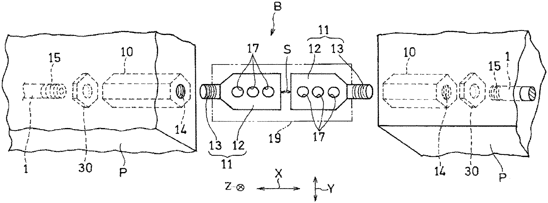
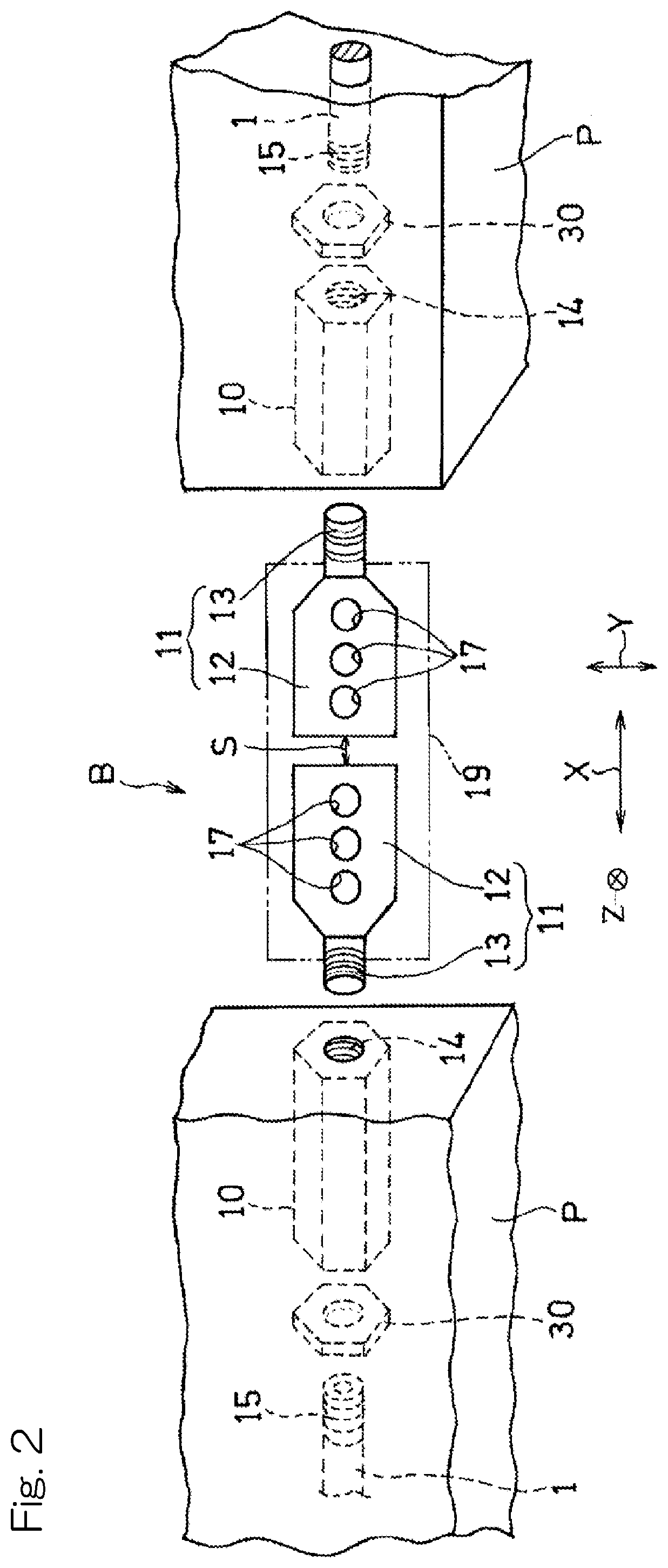
[0020] FIG. 2 is an exploded perspective view of a reinforcing bar joint according to the same embodiment to be threadedly engaged with reinforcing bar male thread parts at end portions of reinforcing bars;
[0021] FIG. 3 is an enlarged perspective view of a joint member of the reinforcing bar joint;
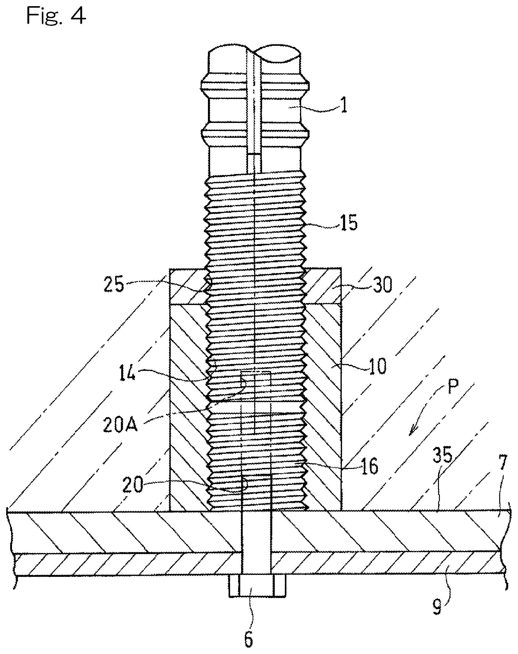
[0022] FIG. 4 is an enlarged cross-sectional view illustrating a different attachment structure between a formwork and an end face of a male thread part of a reinforcing bar;
[0023] FIG. 5 is a side view of the reinforcing bar joint;
[0024] FIG. 6 is a front view of the reinforcing bar joint;
[0025] FIG. 7 is a front view illustrating a case of connecting misaligned reinforcing bars with the reinforcing bar joint, with a connecting member not illustrated in the figure; and
[0026] FIG. 8 is a side view of a reinforcing bar joint according to a second embodiment.
DESCRIPTION OF THE EMBODIMENTS
[0027] Hereinafter, a preferable embodiment of the present invention will be described with reference to the drawings. FIG. 1 is a front view showing reinforcing bar assemblies according to a first embodiment of the present invention which are attached to formworks.
[0028] Structure of Reinforcing Bar Assembly
[0029] FIG. 1 shows one reinforcing bar assembly A located on the right side and another reinforcing bar assembly A located on the left side. These reinforcing bar assemblies may be constructed into a beam or a pillar. This example is described for a case where the reinforcing bar assemblies A are constructed into a beam. The left and right reinforcing bar assemblies A, A are identical, each of which includes a same number of main bars (reinforcing bars) or main reinforcement 1 and a same or different number of stirrups or stirrup reinforcement 2.
[0030] In FIG. 1, each reinforcing bar assembly A includes a plurality of reinforcing bars 1 that serve as the main bars and are arranged with spacing therebetween in a vertical direction and in a depth direction of a plane of FIG. 1 to extend parallel to each other in a left-to-right direction (in this example, a horizontal direction). A plurality of stirrups 2 that serve as shear enforcement bars are wound around these reinforcing bars 1. Each of the reinforcing bars 1 is a deformed bar which includes, on an outer periphery thereof, projections including a rib extending in a longitudinal direction and node portions extending in a circumferential direction at certain intervals. Alternatively, each of the reinforcing bars may be a general round bar.
[0031] Each reinforcing bar 1 has end portions each including a male thread part 15 formed by e.g. rolling. The male thread part 15 may be formed as a separate member from the reinforcing bar 1 and be welded to an end face of the reinforcing bar 1. A cylindrical body 10 including an inner surface including a female thread part is screwed onto the male thread part 15. Attachment thread bodies 6 as described later are inserted from outside the formwork 7 and are screwed into the cylindrical bodies 10 to attach the reinforcing bar assembly A to the formwork 7. The reinforcing bar assembly A on the left side has the same structure.
[0032] Each reinforcing bar assembly A is attached with the formwork 7 in a plant, and fresh concrete is poured into the formwork 7 to produce a precast reinforcing bar concrete body P (hereinafter, simply referred to as "PC concrete body P") for e.g. a beam and a pillar. Alternatively, each reinforcing bar assembly A attached with the formwork 7 may be transferred to a construction site, and fresh concrete may then be poured into the formwork 7 at the site. Alternatively, the reinforcing bars 1, the stirrups 2, the cylindrical bodies 10, and the formworks 7 may be separately transferred to a construction site to obtain the reinforcing bar assemblies A attached with the formworks 7 at the site, and fresh concrete may then be poured into the formworks 7.
[0033] The thread bodies 6 are removed to detach the formwork 7, and the reinforcing bars 1, 1 of the left and right PC concrete bodies P are connected by the reinforcing bar joint B. This example is described for a case where the PC concrete body P is used for a beam. In a case where the PC concrete body P is used for a pillar, the reinforcing bar joint connects reinforcing bars 1, 1 of a pair of upper and lower PC concrete bodies P.
[0034] Structure of Reinforcing Bar Joint
[0035] The reinforcing bar joint B will be described with reference to FIG. 2.
[0036] As illustrated in the exploded perspective view in FIG. 2, the reinforcing bar joint B includes: the above-described cylindrical bodies 10 or couplers each including an inner surface including a female thread part 14; joint members 11 each including one end portion including a joint male thread part 13; and a connecting member 19 connecting a pair of the joint members 11, 11 which face each other.
[0037] The connecting member 19 holds the pair of upper and lower joint members 11 with a sandwich structure such that the joint members 11 are movable in a longitudinal direction (axial direction) X and in an orthogonal direction Y to the longitudinal direction. The longitudinal direction X is common to the joint members 11 and the reinforcing bars 1. The direction Y extends perpendicular to the longitudinal direction X and parallel to a main face of a body part 12 of each joint member 11, i.e., perpendicular to a through hole 17. A direction Z extends perpendicular to both the directions X, Y. The cylindrical bodies 10 are buried into the concrete body P as described above.
[0038] Each cylindrical body 10 has an outer shape having a hexagonal cross-section and includes, on the inner surface thereof, the female thread part 14 configured to be threadedly engaged with a reinforcing bar male thread part 15 which is exposed at an end portion of a reinforcing bar 1. Each cylindrical body 10 may have an outer shape having a round or polygonal cross-section. The reinforcing bar male thread part 15 only comes into thread engagement with an axially inner portion which is a portion of the female thread part 14 of the cylindrical body 10. Each joint member 11 includes, as shown in FIG. 3, a body part 12 having a flat shape and a joint male thread part 13 at a tip of the body part, the joint male thread part being configured to be threadedly engaged with a female thread part 14 of a cylindrical body 10.
[0039] The body part 12 includes three through holes 17 at predetermined intervals (for example, 60 mm) This example includes three through holes 17. Alternatively, there may be two through holes, or four or more through holes. Each of the through holes 17 is a loosely fitting hole (oversized hole) having an inner diameter larger by a few millimeters than an outer diameter of a high-strength bolt or an ultrahigh-strength bolt (hereinafter, sometimes simply referred to as "bolt") 25 which will be described later. Each through hole 17 is provided with friction adjusting parts 17a which are circular projections or chamfers at edge portions on opposite ends of the through hole 17. Thus, when the bolt 25 is fastened with a large force, the projections are crushed or a part of the connecting member 19 enters recesses of the chamfers to provide a greater friction force, so that force transmission action is enhanced.
[0040] As shown in FIG. 2, the identical cylindrical bodies 10 and the identical joint members 11 are arranged in an opposite manner in the longitudinal direction (here, in the horizontal direction because this example is described for a case of beam reinforcing bars), and the joint male thread parts 13 of the respective joint members 11 are threadedly engaged with the corresponding female thread parts 14 of the cylindrical bodies 10. In a case where the engagement may interfere with coupling between the PC concrete bodies P, P, the joint members 11 may be attached to the cylindrical bodies 10 of the PC concrete bodies P at a later point. There is a small gap S (of approximately 70 mm) between the joint members 11, 11. The joint member(s) 11 may be turned to increase or decrease an engaging amount with the cylindrical body (or bodies) 10 and change the size of the gap S, so that a difference in separation distance between the reinforcing bars 1, 1 can be accommodated.
[0041] FIG. 4 illustrates a structure for attaching a reinforcing bar 1 to a formwork 7 of FIG. 1 in an enlarged manner. As shown in FIG. 4, a formwork male thread body 16 includes a predefined threaded hole 20 in an outer end face thereof. The formwork male thread body 16 is attached to the formwork 7 by an attachment thread body 6. The formwork male thread body 16 is brought into thread engagement with a cylindrical body 10, and the female thread part 14 on the inner surface of that cylindrical body 10 is brought into thread engagement with a reinforcing bar male thread part 15 of a reinforcing bar 1. As needed, a lock nut 30 may be fastened thereto.
[0042] In this state, as described above, fresh concrete is poured into the formwork 7 to a filling surface 35, and then the formwork 7 is removed to obtain a PC concrete body P. When connecting the reinforcing bars 1, 1, the formwork male thread body 16 is removed using a tool, so that the female thread part 14 on the inner surface of the cylindrical body 10 is exposed to outside from an end face of the PC concrete body P. The exposed female thread part 14 is brought into thread engagement with a joint male thread part 13 of a joint member 11 as shown in FIG. 2. On an outer side of the formwork 7, an iron frame 9 for positioning the reinforcing bar(s) is removably attached by the attachment thread body 6.
[0043] As a variant of attachment of the reinforcing bar 1 to the formwork 7, it is possible to omit the formwork thread body 16 and provide a longer attachment thread body 6 as illustrated with a two-dot chain line to be threadedly engaged with a threaded hole 20A at the end face of the reinforcing bar 1, so that the reinforcing bar 1 engaged with the cylindrical body 10 can be attached to the formwork 7. In this variant, it is only necessary to remove the formwork 7 to expose the female thread part 14 of the cylindrical body 10 to the outside from the end face of the PC concrete body P.
[0044] The body parts 12, 12 of these joint members 11, 11 are abutted with a pair of connecting members 19, 19 on front and rear sides of the body parts 12 so as to be held with the sandwich structure, as shown in FIG. 5. Each connecting member 19 has a form of a flat plate and includes six coupling holes 27 at positions corresponding to those of the through holes 17 of the joint members 11. Bolts 25, which are an example of fasteners, are inserted from the coupling holes 27 of one of the connecting members 19. The bolts 25 pass through the through holes 17 of the joint member 11, and tip end portions of the bolts 25 project from corresponding coupling holes 27 of the connecting member 19 on the opposite side. Nuts 30 are fastened to the tip end portions of the fasteners (bolts) 25. Accordingly, in this example, the fasteners include the bolts 25 and the nuts 30.
[0045] Each coupling hole 27 is also an oversized hole having an inner diameter larger by a few millimeters than an outer diameter of the fastener 25. According to the Guidebook on Design and Fabrication of Bolted Connections, as for a bolt having a diameter of 24 mm, an oversized hole may have a larger inner diameter by up to +6 mm, and as for a bolt having a diameter of 27 mm, an oversized hole may have a larger inner diameter by up to +8 mm Thus, there are larger gaps between the oversized holes 17, 27 and the bolts 25 than that in case of typical thread engagement, so that these gaps allow the joint members 11, 11 connected by the connecting members 19 to move in the longitudinal direction X and in the orthogonal direction Y to the longitudinal direction. In this way, as shown in FIG. 6, the adjacent PC concrete bodies P, P are coupled to each other by the reinforcing bar joint B.
[0046] Coupling Operation with Reinforcing Bar Joint
[0047] When two reinforcing bars 1, 1 which serve for reinforcement in e.g. a beam or a pillar are coupled to each other by the reinforcing bar joint B, first of all, the joint male thread parts 13 of the joint members 11 are brought into thread engagement with the female thread parts 14 of the cylindrical bodies 10 of FIG. 2. If necessary, lock nuts 31 and washers 32 as shown in FIG. 5 may be attached to the axial outer ends of the cylindrical bodies 10. Thus, with the reinforcing bar male thread parts 15 inserted into the axially inner portions of the female thread parts 14 of the cylindrical bodies 10, the joint male thread parts 13 are threadedly engaged with the axially outer portions which are different parts of the female thread parts.
[0048] In this state, as described above, the joint members 11, 11 are held in a sandwiched manner by the plate-like connecting members 19, 19 on opposite sides. Further, six bolts 25 are inserted through the coupling holes 27 of the connecting members 19 and the coupling holes 17 of the joint members 11, and nuts 30 are threadedly engaged with and fastened to tip end portions of the bolts, if necessary, with washers 32 interposed therebetween. The gap between the PC concrete bodies P, P which are thus coupled to each other is filled by pouring concrete at a site. Therefore, the reinforcing bar joint B is buried in concrete, so that the joint is not exposed to the outside.
[0049] Effects and Advantages
[0050] The reinforcing bar joint B according to the present invention which has the above configuration only involves thread engagement, without using a grout material such as mortar which is expensive and takes a few days to cure, so that it is possible to reduce construction costs and shorten a construction period. Each of the pair of joint members 11 facing each other as shown in FIG. 2 includes the body part 12 and the joint male thread part 13, and the connecting members 19 and the joint members 11 are removably coupled to one another by the fasteners 25, 30 with the body parts 12, 12 of the pair of joint members 11 facing each other in the longitudinal direction. Thus, the coupling structure is simplified. This can expedite and facilitate not only assemblage of reinforcing bars in a plant, but also assemblage of reinforcing bars at a construction site.
[0051] In FIG. 6, the joint members 11, 11 are concentric. As shown in FIG. 7, there may be a misalignment C1 between a longitudinal axis X1 of one of the joint members 11 and a longitudinal axis X2 of the other of the joint members 11, or there may be a positional shift in the axial direction, i.e., a variation in the size of the gap S. Even in such cases, since the through holes 17 of the joint members 11 and the coupling holes 27 of the connecting members 19 are oversized holes, the excess in size can accommodate the misalignment or shift of the reinforcing bars 1, 1, so that the reinforcing bars can be smoothly connected.
[0052] To smoothly fasten the bolts 25, the body parts 12 of the joint members 11 may be turned to an orientation in which the bolts can be easily fastened. In such a case, a misalignment may occur in the Z direction as shown in FIG. 5 to generate a gap between a body part 12 and a connecting member 19. A filler plate may be inserted into this gap. Alternatively, without using a filler plate, since there is the gap S between the joint members 11, 11 in the longitudinal direction X, the bolts 25 may be fastened tightly such that the joint member 11 and the connecting member 19 are deformed to incline so as to eliminate the gap between them in the Z direction.
[0053] Thanks to the structure in which the body parts 12 of the joint members 11 are interposed between the pair of connecting members 19, 19 as shown in FIG. 5, the body parts 12 of the joint members 11 are rigidly held with the sandwich structure by the pair of connecting members 19, 19, so that the reliability of the connection between the pair of reinforcing bars 1, 1 is also improved.
[0054] Further, a reinforcing bar assembly A according to the present embodiment includes a plurality of reinforcing bars 1 arranged parallel to each other and stirrups 2 binding the reinforcing bars. In such a reinforcing bar assembly A, the cylindrical bodies 10 each including the inner surface including the female thread part 14 are threadedly engaged with the reinforcing bar male thread parts 15 on the reinforcing bars 1, with the reinforcing bar male thread parts 15 inserted into the axially inner portions of the female thread parts 14, and the axially outer portions of the female thread parts 14 exposed to the outside of the reinforcing bar assembly A. Therefore, the joint members 11 can be easily coupled to the reinforcing bars 1 by bringing the joint male thread parts 13 of the joint members 11 into thread engagement with the exposed female thread parts 14. As a result, this makes it more efficient to couple the reinforcing bars 1, 1 with the reinforcing bar joint B. Thus, the operation efficiency is improved for both cases where the reinforcing bar concrete structures such as beams and pillars are mass-produced in a plant as well as where concrete is cast at a construction site.
[0055] A reinforcing bar joint according to a second embodiment will be described with reference to FIG. 8. The second embodiment has a same basic configuration as that of the first embodiment as shown in FIG. 5 and only differs from the first embodiment in that the cylindrical bodies 10 of the reinforcing bar joint B are not buried into the PC concrete body P. The male thread parts 15 at the end portions of the reinforcing bars 1 protrude from the PC concrete body P, and the cylindrical bodies 10 are brought into thread engagement with the protruding male thread parts 15 at a construction site. The connection structure of the joint members 11 to the cylindrical bodies 10 and the coupling structure between the joint members 11 and the connecting members 19 are the same as those of the first embodiment.
[0056] Although the present invention has been described in terms of the preferred embodiments thereof with reference to the drawings, various additions, modifications, or deletions may be made without departing from the scope of the invention. Accordingly, such variants are included within the scope of the present invention.
REFERENCE NUMERALS
[0057] A . . . reinforcing bar assembly
[0058] B . . . reinforcing bar joint
[0059] P . . . PC concrete body for e.g. a beam and a pillar
[0060] 1 . . . reinforcing bar
[0061] 2 . . . stirrup
[0062] 6 . . . bolt (fastener)
[0063] 7 . . . formwork
[0064] 10 . . . cylindrical body
[0065] 11 . . . joint member
[0066] 12 . . . body part
[0067] 13 . . . joint male thread part
[0068] 14 . . . female thread part
[0069] 15 . . . reinforcing bar male thread part
[0070] 17 . . . through hole
[0071] 17a . . . friction adjusting part
[0072] 19 . . . connecting member
[0073] 20 . . . threaded hole
[0074] 27 . . . coupling hole
[0075] 30 . . . nut (fastener)
* * * * *
D00000
D00001
D00002
D00003
D00004
D00005
D00006
D00007
D00008
XML
uspto.report is an independent third-party trademark research tool that is not affiliated, endorsed, or sponsored by the United States Patent and Trademark Office (USPTO) or any other governmental organization. The information provided by uspto.report is based on publicly available data at the time of writing and is intended for informational purposes only.
While we strive to provide accurate and up-to-date information, we do not guarantee the accuracy, completeness, reliability, or suitability of the information displayed on this site. The use of this site is at your own risk. Any reliance you place on such information is therefore strictly at your own risk.
All official trademark data, including owner information, should be verified by visiting the official USPTO website at www.uspto.gov. This site is not intended to replace professional legal advice and should not be used as a substitute for consulting with a legal professional who is knowledgeable about trademark law.