Suction Device
Kanstein; Hagen
U.S. patent application number 17/498031 was filed with the patent office on 2022-04-28 for suction device. The applicant listed for this patent is Voith Patent GmbH. Invention is credited to Hagen Kanstein.
| Application Number | 20220127095 17/498031 |
| Document ID | / |
| Family ID | 1000005999171 |
| Filed Date | 2022-04-28 |


| United States Patent Application | 20220127095 |
| Kind Code | A1 |
| Kanstein; Hagen | April 28, 2022 |
SUCTION DEVICE
Abstract
A suction device configured to reliably support or transfer a fiber material web made from glass fibers, fleece material or paper, the suction device including a first guide roller and a second guide roller; a suction box arranged between the first guide roller and the second guide roller; and a permeable clothing that runs over the first guide roller, the second guide roller and the suction box, wherein the suction box includes an operating surface configured to impart a vacuum upon the permeable clothing that runs over the operating surface and upon the fiber material web transported on the permeable clothing during operations, wherein the operating surface is arranged and sized so that it essentially bridges an entire path traveled by the clothing between the first guide roller and the second guide roller; an additional guide roller and an additional suction box over which the permeable clothing is run.
| Inventors: | Kanstein; Hagen; (Duesseldorf, DE) | ||||||||||
| Applicant: |
|
||||||||||
|---|---|---|---|---|---|---|---|---|---|---|---|
| Family ID: | 1000005999171 | ||||||||||
| Appl. No.: | 17/498031 | ||||||||||
| Filed: | October 11, 2021 |
| Current U.S. Class: | 1/1 |
| Current CPC Class: | B65H 2404/153 20130101; B65H 20/14 20130101; B65H 20/02 20130101; B65H 2701/177 20130101; B65H 2406/31 20130101; B65H 2406/363 20130101 |
| International Class: | B65H 20/14 20060101 B65H020/14; B65H 20/02 20060101 B65H020/02 |
Foreign Application Data
| Date | Code | Application Number |
|---|---|---|
| Oct 28, 2020 | DE | DE102020128265.6 |
Claims
1. A suction device configured to reliably support or transfer a fiber material web, the suction device comprising: a first guide roller and a second guide roller; a suction box arranged between the first guide roller and the second guide roller; and a permeable clothing that runs over the first guide roller, the second guide roller and the suction box, wherein the suction box includes an operating surface configured to impart a vacuum upon the permeable clothing that runs over the operating surface and upon the fiber material web transported on the permeable clothing during operations, wherein the operating surface is arranged and sized so that it essentially bridges an entire path traveled by the clothing between the first guide roller and the second guide roller; an additional guide roller and an additional suction box over which the permeable clothing is run, wherein the additional suction box includes an additional operating surface that is configured to impart a vacuum upon the permeable clothing that is run over the additional operating surface and upon the fiber material web transported on the permeable clothing, wherein the additional operating surface is arranged and sized so that it essentially bridges an entire path traveled by the permeable clothing between the additional guide roller and one of the first guide roller and the second suction roller, and wherein the additional suction box is arranged between the first guide roller and the additional guide roller.
2. The suction device according to claim 1, wherein the first guide roller or the second guide roller is not provided with the vacuum.
3. The suction device according to claim 1, wherein the suction box includes a first cambered side wall that is adapted to a diameter of the first guide roller or a second cambered side wall that is adapted to a diameter of the second guide roller.
4. The suction device according to claim 1, wherein the suction box includes a connection at one of two side walls between the first guide roller and the second guide roller so that the suction box is connectable by the connection with a vacuum source.
5. The suction device according to claim 1, wherein the suction box includes at least one format slide configured to adjust a width of the operating surface to a width of the fiber material web.
6. The suction device according to claim 1, wherein the first guide roller, the second guide roller and the additional guide roller are arranged on an identical side of the permeable clothing.
7. The suction device according to claim 1, wherein the additional suction box is configured to apply a different or stronger vacuum upon the permeable clothing and the fiber material web transported thereon compared to the vacuum of the suction box between the first guide roller and the second guide roller during operations.
8. The suction device according to claim 6, wherein a rotation axis of the first guide roller, the second guide roller, and the additional guide roller are not arranged in a common plane but arranged on an enveloping surface of a circular cylinder.
9. The suction device according to claim 1, further comprising: a support roller arranged on a side of the first guide roller, the second guide roller and the additional guide roller that is oriented away from the permeable clothing, wherein the support roller is in supporting contact with the first guide roller, the second guide roller and the additional guide roller.
10. The suction device according to claim 1, wherein the operating surface is configured essentially flat so that the permeable clothing and the fiber material web transported thereon are run in a straight line from the first guide roller to the second guide roller during operations.
11. The suction device according to claim 1, wherein the operating surface is cambered convex so that the permeable clothing and the fiber material web transported thereon are not run in a straight line from the first guide roller to the second guide roller during operations.
12. The suction device according to claim 1, wherein the operating surface has an open surface area between 20% and 100% where the vacuum is applied to the permeable clothing and the fiber material web transported thereon.
13. The suction device according to claim 1, wherein the fiber material web is made from glass fibers, fleece material or paper.
14. A machine for producing or finishing a fiber material web, the machine comprising: at least one suction device according to claim 1.
15. The machine according to claim 14, wherein the fiber material web is made from glass fibers, fleece material or paper.
16. A method, comprising: using a suction device according to claim 1 for transferring a fiber material web between two portions in a machine for producing or finishing the fiber material web or between functional units of the two portions.
17. The method according to claim 16, wherein the operating surface between the first guide roller and the second guide roller includes a retaining zone, wherein the additional operating surface includes a pick up zone, and wherein an open surface area of the retaining zone differs from an open surface area surface of the pickup zone so that a stronger vacuum is applied to the permeable clothing and the fiber material web transported thereon in the retaining zone, than in the pickup zone.
18. The method according to claim 16, wherein the fiber material web includes long fibers.
19. The method according to claim 16, wherein the fiber material web is transferred by closed transfer.
Description
RELATED APPLICATIONS
[0001] This application claims priority from and incorporates by reference German Patent Application DE 10 2020 128 265.6 filed on Oct. 28, 2020.
FIELD OF THE INVENTION
[0002] The invention relates to a suction device configured to reliably support or transfer a fiber material web made from glass fibers, fleece material or paper. Other aspects of the invention relate to a machine for producing or finishing a fiber material web, the machine including at least one suction device of the type recited supra, and to using the suction device.
BACKGROUND OF THE INVENTION
[0003] Guide rollers and suction boxes are typically used in a forming section of a paper machine so that this combination is known in the art even though the suction boxes typically only have the function of dehumidifying the fiber material web but do not have the function of reliably supporting or transferring the fiber material web. Arranging a suction box between two guide rollers wherein the operating surface of the suction box is arranged and sized so that the suction box bridges essentially an entire path that is traveled by the clothing between the two guide rollers is known e.g.; from FIG. 2 of DE 10 2004 055 139 A1 and FIG. 1 of DE 29 22 623 A1.
[0004] However, when the fiber material web is to be transferred between two different drive groups or the fiber material web is to be reliably retained on a clothing while another clothing is run above the fiber material web and away from the fiber material web today typically suction rollers are used in machines for producing or finishing fiber material webs. The transfer between different drive groups can be e.g.; the transfer between the forming portion and the pressing portion of a paper production machine or the transfer from a felt of a first press arrangement to a felt of a second press arrangement within the press portion.
[0005] In particular when the fiber material web includes long fibers or is substantially formed from long fibers like e.g.; in very open papers or fleeces or glass fiber webs guide rollers are required that have very large open surface areas. This requirement comes from the fact that holes in a roller jacket of conventional suction rollers that only have a relatively small open surface areas clog with fibers rather quickly.
[0006] There are suction rollers with large open surface areas that are suitable for producing or finishing fiber material webs with long fibers, however they have various disadvantages. On the one hand side, their configuration is complex since there are certain requirements with respect to sealing bars and spray tubes. Additionally a user of such suction rollers should always have a spare roller stored close to the machine. On the other hand, side, the rollers generate a rather high level of noise during operations. This comes from the fact that the vacuum in the holes of the roller jacket collapse as soon as the holes move out of a zone of the suction roller where the vacuum is applied.
[0007] Additionally, vacuum is applied to the suction rollers by fans or water ring air pumps. A substantial portion of the suction volume is required in order to adapt the open surface area of the suction portion to the vacuum of the suction portion. This makes operating the guide rollers very energy intensive and expensive.
[0008] For slow running machines there is an option to use a suction box with a stationary surface instead of the suction roller, however the clothing that is run over the suction box and which is typically deflected in the suction portion to a large extent is subject to strong wear.
[0009] A suction device of the generic type recited supra according to the preamble of claim 1 is known from FIG. 2 of DE 199 55 030 A1. A roller 14 which is part of a shoe pressing arrangement and a suction roller 34 are arranged adjacent to each other with a suction box 52 arranged therebetween. Another suction roller 36 is arranged in the process direction downstream of the suction roller 34, however on a side of the roller 24 and the suction roller 34 that are arranged opposite to the clothing 22. Another suction box 54 is arranged directly downstream of the suction roller 34 also on the opposite side. The actual transfer of the fiber material web from the clothing 22, to another clothing 28 is performed by a suction roller, namely the additional suction roller 36 which has the disadvantages recited supra.
BRIEF SUMMARY OF THE INVENTION
[0010] Thus, it is an object of the invention to overcome or at least mitigate the disadvantages recited supra. This object is achieved by the features of the independent claims. Advantageous embodiments are defined in the dependent claims.
[0011] According to the invention the generic suction device described supra is improved so that the additional suction box is arranged between the first guide roller and the additional guide roller. Since the two suction boxes are arranged between the three rollers it is clear that all suction boxes are arranged on the same side of the clothing.
[0012] The invention proposes a suction device configured to reliably support or transfer a fiber material web made from glass fibers, fleece material or paper, the suction device including a first guide roller and a second guide roller; a suction box arranged between the first guide roller and the second guide roller; and a permeable clothing that runs over the first guide roller, the second guide roller and the suction box, wherein the suction box includes an operating surface configured to impart a vacuum upon the permeable clothing that runs over the operating surface and upon the fiber material web transported on the permeable clothing during operations, wherein the operating surface is arranged and sized so that it essentially bridges an entire path traveled by the clothing between the first guide roller and the second guide roller, an additional guide roller and an additional suction box over which the permeable clothing is run; an additional operating surface that is configured to impart a vacuum upon the permeable clothing that is run over the additional operating surface and upon the fiber material web transported on the permeable clothing, wherein the additional operating surface is arranged and sized so that it essentially bridges an entire path traveled by the permeable clothing between the additional guide roller and one of the first guide roller and the second suction roller, and wherein the additional suction box is arranged between the first guide roller and the additional guide roller.
[0013] This way several zone with different pressures can be provided and/or gentler deflections can be achieved.
[0014] With respect to the different pressure zones, it is advantageously provided that the additional suction box is configured to impart a different, in particular stronger vacuum upon the clothing and upon the fiber material web transported on the clothing compared to the vacuum of the suction box between the first guide roller and the second guide roller. Thus, the fiber material web can be initially removed from another clothing under a stronger vacuum relative to the other clothing in a pickup zone and then transferred under a weaker vacuum in a retaining zone. A weaker vacuum can be achieved in that a vacuum in the suction box for the retaining zone is weaker than a vacuum within the additional suction box for the pickup zone and/or when there is an identical vacuum in the two suction boxes it can be achieved by differently sized open surface areas in the operating surfaces of the two suction boxes.
[0015] With respect to the gentler deflection, it is advantageous when rotation axes of the first guide roller, the second guide roller and the additional guide roller are not in an identical plane. The rotation axes can be arranged in particular on an enveloping surface of a cylinder. This facilitates supporting all three guide rollers at a common support roller.
[0016] According to the invention the respective operating surfaces are arranged and sized so that they bridge essentially an entire path that is traveled by the clothing between the respective guide rollers. Essentially means in this context that at least 70%, advantageously at least 90% more advantageously 95% of the respective path is being bridged.
[0017] According to the invention, the two guide rollers and the additional guide roller provide that the clothing with the fiber material web transported thereon can be guided and deflected with very little wear. Therefore, the rollers can have a very simple configuration which makes for economical acquisition and operations. Advantageously the rollers are not provided with vacuum so that the vacuum cannot collapse in bore holes in the roller jacket which reduces noise during operations. Retaining the fiber material web on the permeable clothing is provided by the vacuum from the suction box. The suction box being a stationary element can also be configured in a very simple manner so that it is easy to clean. Since the guide and deflection function is primarily performed by the guide rollers wear between the operating surface of the suction box and the clothing that is run over the operating surface can be kept to a minimum.
[0018] The inventors have found that it is important that the operating surface of the suction box extends essentially over an entire path between the two guide rollers in order to efficiently replace the suction rollers with their disadvantages described supra with the suction device according to the invention. Only this assures that the suction and retaining effect is already reliably provided proximal to the respective support roller.
[0019] In order to facilitate this and in order to fit the suction box in an optimum manner into a free portion between the two adjacent guide rollers it is advantageous for the suction box to have a first side wall that is cambered according to the diameter of the first guide roller and/or a second side wall that is cambered according to the diameter of the second guide roller. Advantageously both side walls are cambered accordingly.
[0020] Additionally, the suction box can have a connection at one of its two faces arranged between the two guide rollers, wherein the suction box is connected or connectable with a vacuum source by the connection.
[0021] Thus, the suction box can essentially have two side walls that are cambered according to radii of the guide rollers, and two face plates that extend on the guide and drive side between the two guide rollers wherein at least one face plate has a vacuum connection, a coating that is oriented towards the clothing and that defines the operating surface that is more or less open, and a cover that is oriented away from the clothing.
[0022] In particular when fiber material webs with different widths are to be produced or finished in the machine that uses the suction device according to the invention it is advantageous when the suction device includes at least one format slide that facilitates adjusting a width of the operating surface according to a width of the fiber material web. Advantageously the suction box respectively includes at least one format slide at both side edges.
[0023] Advantageously the suction device includes a support roller that is arranged on a side of the first guide roller, the second guide roller and optionally the additional guide roller that is oriented away from the clothing and that is in supporting contact with the guide rollers. Thus, the guide rollers themselves can be configured rather small and easy to handle without running a risk of the guide rollers being deformed in an impermissible manner by forces imparted upon the guide rollers by the deflected clothing. Using a common support roller certainly requires that all guide rollers supported by the support roller have an identical diameter. It is advantageous anyhow to configured all guide rollers identical since storing a single spare guide roller typically suffices to insure reliable operations.
[0024] The suction box has a rather simple configuration when the operating surface is configured flat so that the clothing and the fiber material web transported thereon are run by closed transfer from the first guide roller to the second guide roller during operations. Closed transfer means that the fiber material web is supported by the clothing substantially continuously besides a small gap in some transfers. This also minimizes wear through friction between the operating surface and the clothing.
[0025] However, it can be advantageous under certain conditions to configure the operating surface essentially cambered so that the clothing and the fiber material web transported thereon are not run by closed transfer from the first guide roller to the second guide roller during operations. However, the curvature should not be too pronounced and a minimum curvature radius of the operating surface should be selected sufficiently large to keep wear due to the deflection at a minimum.
[0026] As recited supra it is important for reliably guiding or transferring a fiber material web with long fibers that the surface where the vacuum is applied has an open portion that is as large as possible. Therefore, it is proposed that the operating surface has an open surface between 20% and 100%, advantageously between 50% and 100%, further advantageously between 75% and 100%. In fact, the open surface can even be 100% in an extreme case which means that a side of the suction box that is oriented towards the clothing is essentially completely open besides the format slides. Typically, the clothing is supported in this portion by a support structure, e.g. by a plurality of struts that are oriented parallel to each other and offset from each other and which extend advantageously orthogonal to a movement direction of the clothing during operations. Care should be taken to select a material of the support structure so that a slide friction coefficient between the support structure and the clothing is as small as possible. Thus, the support structure can have a ceramic surface.
[0027] Another aspect of the instant invention relates to a machine for producing or finishing a fiber material web like e.g.; a glass fiber, fleece material or paper web, the machine comprising at least one suction device according to the invention as described supra.
[0028] Another aspect of the instant invention relates to using the suction device for transferring a fiber material web, in particular with long fibers advantageously by closed transfer between two sections in a machine for producing or finishing the fiber material web or between two functional portions of these sections. When transferring the fiber material web, the suction device according to the invention can be used in a particularly advantageous manner.
[0029] The suction device according to the invention with the additional guide roller and the additional suction box can be used as a replacement for a pickup roller. Thus, it is particularly advantageous, when the operating surface between the first guide roller and the second guide roller provides a retaining zone whereas the additional operating surface provides a pickup zone wherein a vacuum that is applied to the clothing and the fiber material web transported thereon in the retaining zone differs from a vacuum that is applied upon the clothing and the fiber material web transported thereon in the pickup zone. Both suction boxes can be connected to the same vacuum source for the purposes of simplicity but can have contact surfaces that differ with respect to their open surface areas.
BRIEF DESCRIPTION OF THE DRAWINGS
[0030] The invention is subsequently described in more detail based on embodiments with reference to drawing figures, wherein:
[0031] FIG. 1A illustrates a first prior art suction device;
[0032] FIG. 1B illustrates a variation of the embodiment of FIG. 1A;
[0033] FIG. 2 illustrates a first embodiment of a suction device according to the invention;
[0034] FIG. 3 illustrates a transfer device including a prior art suction roller;
[0035] FIG. 4 illustrates a combination of embodiments according to FIGS. 1A and 2, which can be used as a replacement for the transfer device according to FIG. 3; and
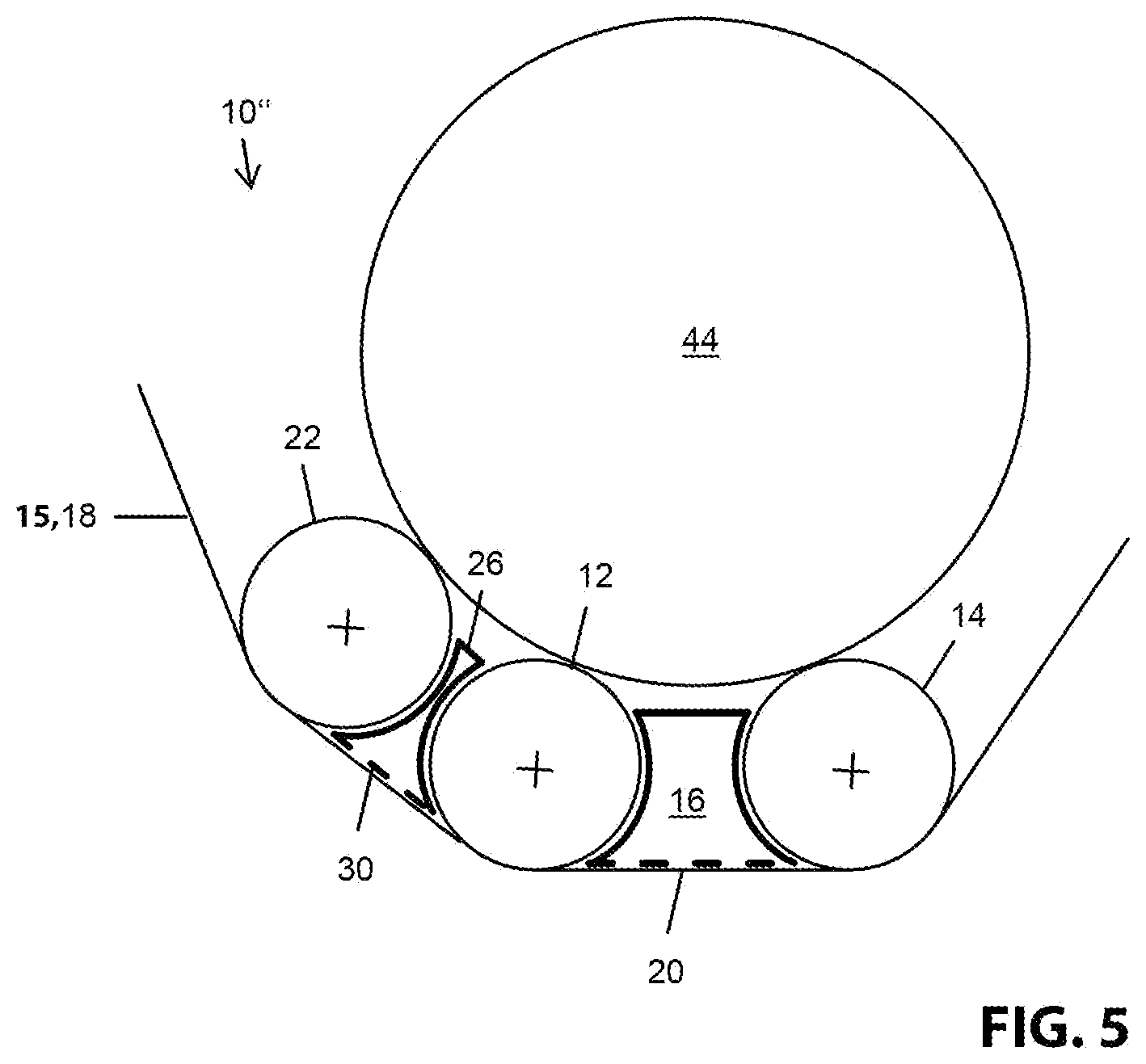
[0036] FIG. 5 illustrates a second embodiment of the suction device according to the invention.
DETAILED DESCRIPTION OF THE INVENTION
[0037] FIG. 1A schematically illustrates a simple prior art suction device 10. The suction device 10 includes a first guide roller 12, a second guide roller 14 and a suction box 16 arranged between the first guide roller 12 and the second guide roller 14. Furthermore the suction device 10 includes a permeable clothing 18 that is run over a circumferential section of the first guide roller 12, an operating surface 20 of the suction box 16 that is drawn in dashed lines and a circumferential section of the second guide roller 14.
[0038] The clothing 18 is an endless revolving clothing wherein FIG. 1A merely illustrates a section thereof. At least in the portion where the clothing 18 is run over the operating surface 20 of the suction box 16, a fiber web 15 can be transported on a side of the clothing 18 that is oriented away from the operating surface 20 during operations. When the suction box is connected with a vacuum source, e.g.; through a connection 17 at a face of the vacuum box during operations the vacuum impacts the clothing 18 through the operating surface and impacts the fiber material web 15 through the clothing 18 since the clothing 18 is permeable. Thus, the fiber material 15 web is reliably retained on the clothing 18 and guided together with the clothing 18 over a portion of the operating surface 20.
[0039] According to the invention the operating surface 20 is arranged and sized so that it covers essentially an entire path that is traveled by the clothing 18 between the first guide roller 12 and the second guide roller 14. Thus, the suction box 16 can have a first cambered side wall 21 that is adapted to a diameter of the first guide roller 12 and a second cambered side wall 21 that is adapted to a diameter of the second guide roller 14. Furthermore, the suction box 16 can include a cover that is arranged opposite to the operating surface 20 and a face plate on a guide side and on a drive side wherein at least one of the two face plates includes a connection 17 for a vacuum source.
[0040] The operating surface 20 of the suction box can have a relatively large open surface depending on the application. The operating surface can have a number of struts that are oriented parallel to each other and offset from each other wherein the struts advantageously run in a direction that is orthogonal to the movement direction of the clothing during operations. In an extreme case the open surface can also be 100%, this means the suction box 16 is essentially completely open towards the clothing 18.
[0041] Additionally, the suction box 16 can also include format slides 19 that are adjustable in a transversal direction of the machine, this means orthogonal to the image plane of FIG. 1A in order to adjust the width of the operating surface 20 to the width of the fiber material web.
[0042] FIG. 1B illustrates a variation of the embodiment of FIG. 1A. Therefore, only differences of FIG. 1B over the embodiment of FIG. 1A are being described infra. In the variation according to FIG. 1B the suction box 16 is configured so that it can impart vacuums with different strengths upon the clothing and the fiber material web transported thereon in two different zones. One of the zones can be used as a so-called pickup zone, whereas the other zone can function as a so-called retaining zone. In order to form the different vacuums in the two zones, the suction box can have an interior divider wall so that two suction box sections 16.1 and 16.2 are provided that can have vacuums with different strengths. Alternatively, or additionally the operating surface 20 can have two sections 20.1 and 20.2, with open surface areas with different sizes.
[0043] FIG. 2 illustrates a first embodiment of a suction device 10' according to the invention. This is an improvement upon the suction device 10 according to the embodiment in FIG. 1A. Thus, identical reference numerals are being used for the same components and component sections as in FIG. 1A and the description of FIG. 1A is being referred to.
[0044] The first embodiment according to the invention according to FIG. 2 differs from the embodiment in FIG. 1A essentially in that an additional guide roller 22 is provided upstream of the first guide roller 12 viewed in a movement direction of the clothing 18 and an additional suction box 26 is provided between the additional guide roller 22 and the first guide roller 12. The clothing 18 and the fiber material web transported thereon is initially transported over a circumferential section of the additional guide roller 22 and then over an additional operating surface 30 of the additional suction box 26 before the clothing and the fiber material web reach a circumferential section of the first guide roller 12 during operations.
[0045] Advantageously the three guide rollers 12, 14, and 22 are essentially configured identical. Thus, no separate spare rollers have to be stocked for each of the guide rollers. Additionally, the guide rollers 12, 14 and 22 have a rather simple configuration and vacuum is not applied to them. Rotation axes of the guide rollers that are indicated by crosses in the drawing figures are advantageously all arranged on a common circular cylindrical enveloping surface.
[0046] The additional suction box 26 can have the same structure in principle as described supra for the suction box 16. In the illustrated embodiment, the suction box 26 differs from the suction box 16 in being narrower since a distance between the additional guide roller 22 and the first guide roller 12 is smaller than a distance between the first guide roller 12 and the second guide roller 14. Thus, also the additional operating surface 30 of the additional suction box 26 is configured shorter than the operating surface 20 of the suction box 16. Furthermore the additional operating surface 30 can have a different open surface area than the operating surface 20 so that different vacuums are applied to the clothing 18 and the fiber material web transported thereon in both portions of the suction boxes 16 and 26 even when both suction boxes 16 and 26 are connected to the same vacuum source.
[0047] FIG. 4 illustrates schematically how a combination of the embodiment 10 according to FIG. 1 and the first embodiment 10' according to FIG. 2 can be used to replace a known transfer device with a suction roller as illustrated in FIG. 3.
[0048] In the prior art transfer device 32*, a fiber material web is transferred from a first clothing 34, coming from the top left in FIG. 3 to a second clothing 36 that moves to the right in FIG. 3. The first clothing 34 is run in the transfer portion over a first pulley roller 38 that is not provided with a vacuum. By the same token, the second clothing 36 is run in the transfer portion over a second pulley roller 40. Differently from the first pulley roller 38 the second pulley roller 40 can be provided with vacuum in sections in order to be able to reliably transfer the fiber material web to the second clothing 36.
[0049] In order to reliably transfer the fiber material web from the first clothing 34 to the second clothing 36, the transfer device 32* includes a suction roller 42. This suction roller is rather complex. in order to also be able to transfer fiber material webs with long fibers, the suction roller needs a roller jacket with a rather large open surface area. Since this is rather difficult to do with bore holes, suction rollers with jackets with a honeycomb geometry are being used, in particular triangular honeycombs or hexagonal honeycombs that are welded together or soldered together. Otherwise, there is a risk that the suction openings might clog. Additionally, the suction roller 42 typically includes at least two different suction zones, namely at least one pickup zone that is arranged opposite to the first pulley roller 38 and a retaining zone that retains the fiber material web between the first pulley roller 38 and the second pulley roller 40.
[0050] FIG. 4 illustrates how the complicated pulley roller 42, of FIG. 3 is replaced by the suction device 10' according to the first embodiment of FIG. 2. Furthermore FIG. 4 illustrates how the suction activated second pulley roller 40 of FIG. 3 is replaced by the suction device 10 according to the embodiment of FIG. 1A. With respect to these two embodiments the description provided supra regarding FIGS. 1A and 3 is being referred to wherein the clothing 18 in FIG. 1A corresponds to the second clothing 36. The suction devices 10 and 10' provide a transfer device 32 for reliably transferring the fiber web by closed transfer from the first clothing 34 to the second clothing 36 without using suction rollers that have the problems described supra. The instant invention is particularly advantageous when the fiber material web to be transferred includes long fibers or is substantially formed from long fibers. It is appreciated that the prior art transfer device according to FIG. 3 does not transfer the fiber material web by closed transfer but with a small gap of approximately 2 mm. Using the transfer device 32 according to FIG. 4 it is possible to transfer the fiber material web by closed transfer, however alternatively it is also possible to transfer the fiber material web with a small gap like in the prior art.
[0051] When the operating surface 30 of the additional suction box 26 has a different open surface area than the operating surface 20 of the suction box 16 of the suction device 10', it is possible to apply a different vacuum to the fiber material web transported on the clothing 18 in the portion of the additional suction box compared to the vacuum in the portion of the suction box 16, even when the two suction boxes 16 and 26 are connected with the same vacuum source. Thus, a pickup zone with a stronger vacuum can be arranged opposite to the first pulley roller 38 and a retaining zone with a weaker vacuum can be arranged between the first clothing 34 and the second clothing 36. The portion where the clothing 18 and the fiber material web transported thereon are run about a circumferential section of the first guide roller 12 of the suction device 10' without a vacuum being applied can be kept rather small since the respective operating surfaces 20, 30 according to the invention are arranged and size so that they bridge essentially an entire path that is traveled by the clothing 18 between the guide rollers 22, 12 and 14.
[0052] FIG. 5 illustrates a second embodiment of the suction device 10'' according to the invention. This is a variation of the suction device 10' according to the first embodiment according to the invention. Thus, identical reference numerals like in FIG. 2 are used for identical components and component sections and the description provided supra for FIG. 2 is being referred to.
[0053] The second embodiment according to FIG. 3 differs from the first embodiment according to FIG. 2 in that an additional support roller 44 is provided that is arranged at a side of the first guide roller 12, the second guide roller 14 and the additional guide roller 22 that is oriented away from the clothing 18 and that is in supporting contact with the guide rollers 12, 14 and 18. This way the guide rollers 12, 14 and 18 can be configured rather small and inexpensive without incurring a risk of them bending by an impermissible amount due to forces applied to them by the deflected clothing 18.
REFERENCE NUMERALS AND DESIGNATIONS
[0054] 10, 10', 10'' suction device [0055] 12 first guide roller [0056] 14 second guide roller [0057] 15 fiber material web [0058] 16 suction box [0059] 16.1, 16.2 suction box section [0060] 17 connection [0061] 18 clothing [0062] 19 format slide [0063] 20 operating surface [0064] 20.1, 20.2 operating surface section [0065] 21 cambered side wall [0066] 22 additional guide roller [0067] 26 additional suction box [0068] 30 additional operating surface [0069] 32, 32* transfer device [0070] 34 first clothing [0071] 36 second clothing [0072] 38 first pulley roller [0073] 40 second pulley roller [0074] 42 suction roller [0075] 44 support roller
* * * * *
D00000
D00001
D00002
D00003
XML
uspto.report is an independent third-party trademark research tool that is not affiliated, endorsed, or sponsored by the United States Patent and Trademark Office (USPTO) or any other governmental organization. The information provided by uspto.report is based on publicly available data at the time of writing and is intended for informational purposes only.
While we strive to provide accurate and up-to-date information, we do not guarantee the accuracy, completeness, reliability, or suitability of the information displayed on this site. The use of this site is at your own risk. Any reliance you place on such information is therefore strictly at your own risk.
All official trademark data, including owner information, should be verified by visiting the official USPTO website at www.uspto.gov. This site is not intended to replace professional legal advice and should not be used as a substitute for consulting with a legal professional who is knowledgeable about trademark law.