Golf Club Shaft
NAKANO; Takashi
U.S. patent application number 17/491619 was filed with the patent office on 2022-04-28 for golf club shaft. This patent application is currently assigned to SUMITOMO RUBBER INDUSTRIES, LTD.. The applicant listed for this patent is SUMITOMO RUBBER INDUSTRIES, LTD.. Invention is credited to Takashi NAKANO.
| Application Number | 20220126178 17/491619 |
| Document ID | / |
| Family ID | |
| Filed Date | 2022-04-28 |


| United States Patent Application | 20220126178 |
| Kind Code | A1 |
| NAKANO; Takashi | April 28, 2022 |
GOLF CLUB SHAFT
Abstract
A shaft includes a tip end, a butt end, flexural rigidities E1 to E10 at respective points that are located 130 mm, 230 mm, 330 mm, 430 mm, 530 mm, 630 mm, 730 mm, 830 mm, 930 mm, and 1030 mm apart from the tip end. A ratio (E8/E1) is greater than or equal to 2 and less than or equal to 7. The flexural rigidity E1 is less than or equal to 2.5 (kgfm.sup.2). The flexural rigidity E8 is greater than or equal to 5.0 (kgfm.sup.2). When a formula of a straight line that passes through a point (230, E2) and a point (630, E6) is represented by y=ax+b, the shaft satisfies the following relationships R1 and R8: (130a+b)<E1.ltoreq.(130a+b+0.5) (R1), and (830a+b)<E8.ltoreq.(830a+b+1.0) (R8).
| Inventors: | NAKANO; Takashi; (Kobe-shi, JP) | ||||||||||
| Applicant: |
|
||||||||||
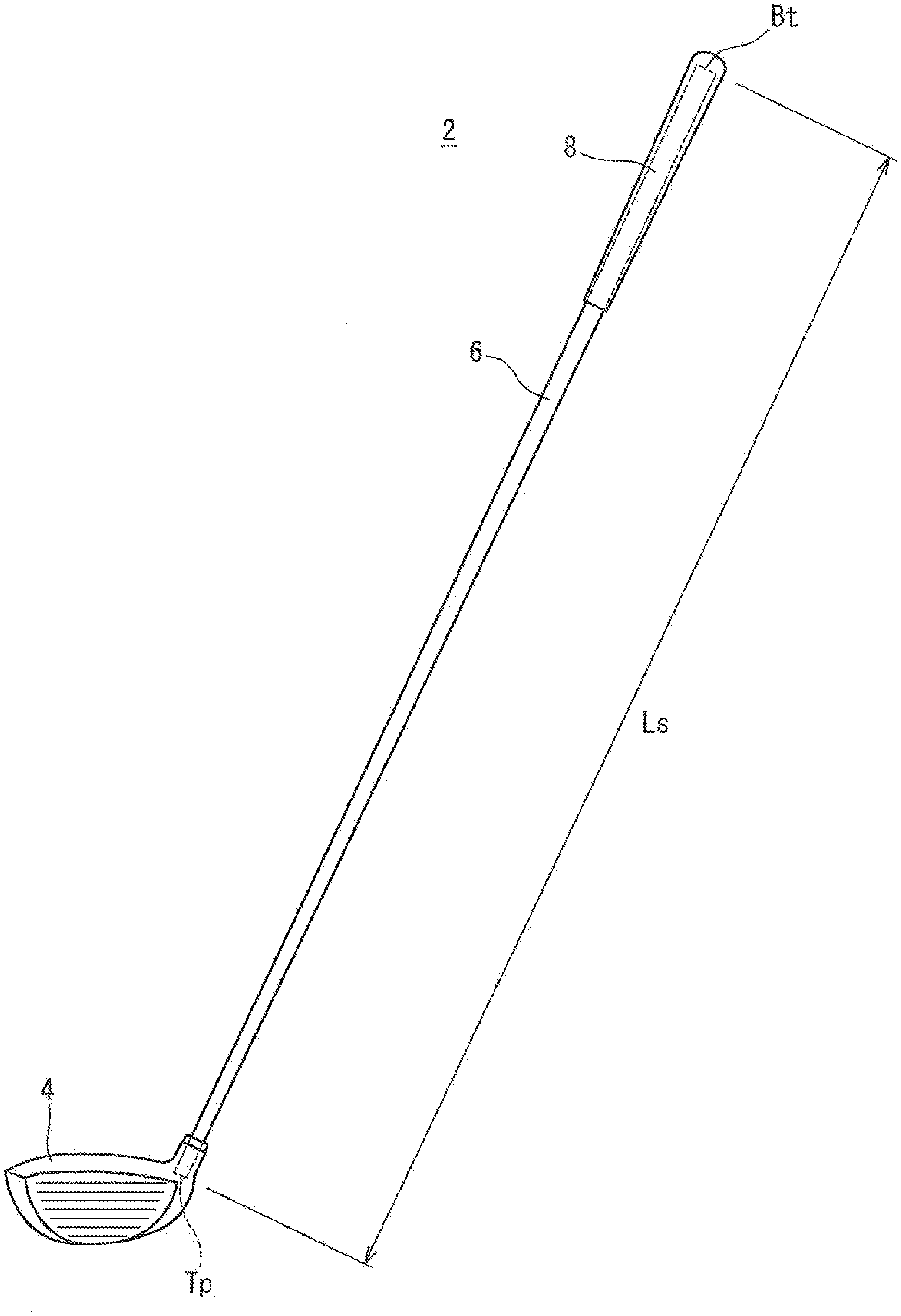
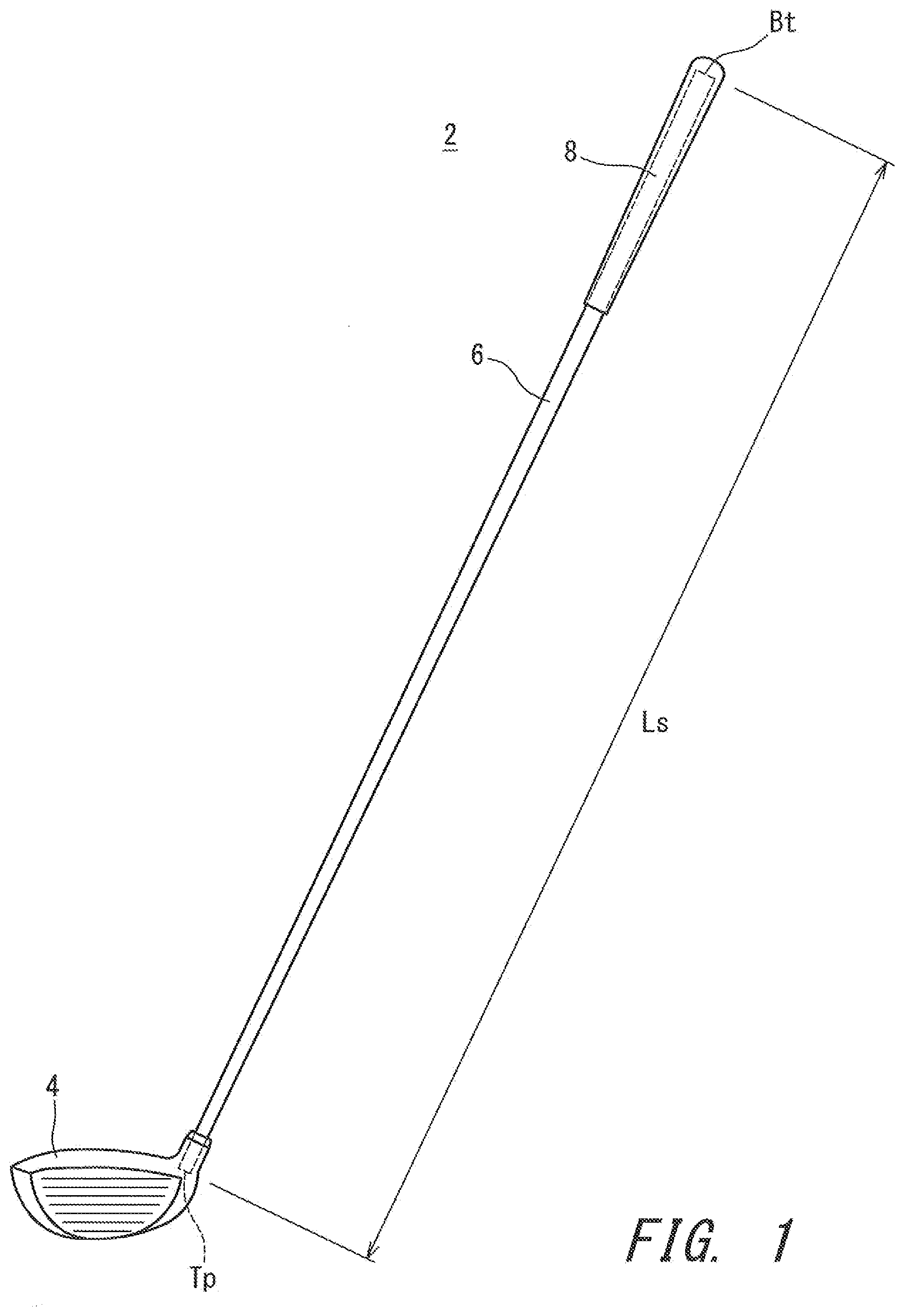
|---|---|---|---|---|---|---|---|---|---|---|---|
| Assignee: | SUMITOMO RUBBER INDUSTRIES,
LTD. Kobe-shi JP |
||||||||||
| Appl. No.: | 17/491619 | ||||||||||
| Filed: | October 1, 2021 |
| International Class: | A63B 53/10 20060101 A63B053/10; A63B 60/00 20060101 A63B060/00 |
Foreign Application Data
| Date | Code | Application Number |
|---|---|---|
| Oct 22, 2020 | JP | 2020-177560 |
Claims
1. A golf club shaft comprising: a tip end; a butt end; a flexural rigidity E1 at a point located 130 mm apart from the tip end; a flexural rigidity E2 at a point located 230 mm apart from the tip end; a flexural rigidity E3 at a point located 330 mm apart from the tip end; a flexural rigidity E4 at a point located 430 mm apart from the tip end; a flexural rigidity E5 at a point located 530 mm apart from the tip end; a flexural rigidity E6 at a point located 630 mm apart from the tip end; a flexural rigidity E7 at a point located 730 mm apart from the tip end; a flexural rigidity E8 at a point located 830 mm apart from the tip end; a flexural rigidity E9 at a point located 930 mm apart from the tip end; and a flexural rigidity E10 at a point located 1030 mm apart from the tip end, wherein a ratio (E8/E1) is greater than or equal to 2 and less than or equal to 7, the flexural rigidity E1 is less than or equal to 2.5 (kgfm.sup.2), the flexural rigidity E8 is greater than or equal to 5.0 (kgfm.sup.2), when a formula of a straight line that passes through a point (230, E2) and a point (630, E6) plotted in a graph on an orthogonal coordinate system having an x-axis that represents a distance (mm) from the tip end and a y-axis that represents a flexural rigidity (kgfm.sup.2) is indicated by y=ax+b, the golf club shaft satisfies the following relationships R1 and R8: (130a+b)<E1.ltoreq.(130a+b+0.5) (R1), and (830a+b)<E8.ltoreq.(830a+b+1.0) (R8).
2. The golf club shaft according to claim 1, wherein the golf club shaft further satisfies the following relationship R81: (830a+b+0.3).ltoreq.E8.ltoreq.(830a+b+1.0) (R81).
3. The golf club shaft according to claim 1, wherein the flexural rigidity E9 is less than or equal to (930a+b-0.1).
4. The golf club shaft according to claim 1, wherein the flexural rigidity E10 is less than or equal to (1030a+b-0.6).
5. The golf club shaft according to claim 1, wherein the golf club shaft further satisfies the following relationships R3, R4 and R5: (330a+b-0.2)<E3.ltoreq.(330a+b+0.2) (R3), (430a+b-0.2)<E4.ltoreq.(430a+b+0.2) (R4), and (530a+b-0.2)<E5.ltoreq.(530a+b+0.2) (R5).
6. The golf club shaft according to claim 1, wherein the golf club shaft is formed by a plurality of carbon fiber reinforced resin layers, the carbon fiber reinforced resin layers include an intermediate partial bias layer that is disposed apart from the tip end and apart from the butt end, and an axial directional region in which the intermediate partial bias layer is disposed includes a point 830 mm apart from the tip end.
7. The golf club shaft according to claim 6, wherein the intermediate partial bias layer has a length in an axial direction of greater than or equal to 250 mm and less than or equal to 550 mm.
8. The golf club shaft according to claim 1, wherein the flexural rigidity E3 is less than (330a+b), the flexural rigidity E4 is less than (430a+b), and the flexural rigidity E5 is less than (530a+b).
9. The golf club shaft according to claim 1, wherein the flexural rigidity E7 is greater than (730a+b).
10. The golf club shaft according to claim 1, wherein the flexural rigidity E10 is less than (1030a+b).
11. The golf club shaft according to claim 1, wherein the flexural rigidity E3 is less than (330a+b), the flexural rigidity E4 is less than (430a+b), the flexural rigidity E5 is less than (530a+b), the flexural rigidity E7 is greater than (730a+b), and the flexural rigidity E10 is less than (1030a+b).
12. The golf club shaft according to claim 1, wherein the flexural rigidity E10 is less than the flexural rigidity E8.
13. The golf club shaft according to claim 1, wherein the flexural rigidity E10 is less than the flexural rigidity E9.
14. The golf club shaft according to claim 9, wherein an absolute value of [E7-(730a+b)] is greater than an absolute value of [E3-(330a+b)], the absolute value of [E7-(730a+b)] is greater than an absolute value of [E4-(430a+b)], and the absolute value of [E7-(730a+b)] is greater than an absolute value of [E5-(530a+b)].
15. The golf club shaft according to claim 8, wherein an absolute value of [E8-(830a+b)] is greater than an absolute value of [E3-(330a+b)], the absolute value of [E8-(830a+b)] is greater than an absolute value of [E4-(430a+b)], and the absolute value of [E8-(830a+b)] is greater than an absolute value of [E5-(530a+b)].
Description
CROSS REFERENCE TO RELATED APPLICATION
[0001] This application claims priority to Japanese Patent Application No. 2020-177560 filed on Oct. 22, 2020. The entire contents of this Japanese Patent Application are hereby incorporated by reference.
BACKGROUND
Technical Field
[0002] The present disclosure relates to golf club shafts.
Description of the Related Art
[0003] Physical properties of a golf club shaft, such as flexural rigidity and torsional rigidity, can be varied depending on positions of the golf club shaft. The performance of the shaft can be changed by the distribution of physical properties.
[0004] JP2003-169871A discloses a shaft in which: a position having a minimum flexural rigidity in the shaft is present in a region that extends from 15% to 45% of the shaft full length from the shaft tip end; and a flexural rigidity at a position in a region that extends from the shaft tip end to less than or equal to 10% of the shaft full length is 1.2 to 2.5 times the minimum flexural rigidity.
SUMMARY
[0005] Shafts are required to exhibit excellent performances regarding flight distance, feeling, and directional stability of hit balls, for example. The inventor of the present disclosure has found that a new distribution of flexural rigidity that is different from conventional distributions can improve performance of shafts.
[0006] One example of the present disclosure is to provide a golf club shaft that is excellent in flight distance performance.
[0007] A golf club shaft according to one aspect includes a tip end, a butt end, a flexural rigidity E1 at a point located 130 mm apart from the tip end, a flexural rigidity E2 at a point located 230 mm apart from the tip end, a flexural rigidity E3 at a point located 330 mm apart from the tip end, a flexural rigidity E4 at a point located 430 mm apart from the tip end, a flexural rigidity E5 at a point located 530 mm apart from the tip end, a flexural rigidity E6 at a point located 630 mm apart from the tip end, a flexural rigidity E7 at a point located 730 mm apart from the tip end, a flexural rigidity E8 at a point located 830 mm apart from the tip end, a flexural rigidity E9 at a point located 930 mm apart from the tip end, and a flexural rigidity E10 at a point located 1030 mm apart from the tip end. A ratio (E8/E1) is greater than or equal to 2 and less than or equal to 7. The flexural rigidity E1 is less than or equal to 2.5 (kgfm.sup.2). The flexural rigidity E8 is greater than or equal to 5.0 (kgfm.sup.2). In a graph on an orthogonal coordinate system having an x-axis that represents a distance (mm) from the tip end and a y-axis that represents a flexural rigidity (kgfm.sup.2), when a formula of a straight line that passes through a point (230, E2) and a point (630, E6) is indicated by y=ax+b, the golf club shaft satisfies the following relationships R1 and R8:
(130a+b)<E1.ltoreq.(130a+b+0.5) (R1), and
(830a+b)<E8.ltoreq.(830a+b+1.0) (R8).
BRIEF DESCRIPTION OF THE DRAWINGS
[0008] FIG. 1 shows an overall view of a golf club that includes a golf club shaft according to a first embodiment;
[0009] FIG. 2 is a developed view of the golf club shaft in FIG. 1;
[0010] FIG. 3 is a schematic diagram illustrating a method for measuring a flexural rigidity EI;
[0011] FIG. 4 shows a graph on an orthogonal coordinate system having an x-axis that represents a distance (mm) from a tip end and a y-axis that represents a flexural rigidity (kgfm.sup.2); and
[0012] FIG. 5 is a developed view of a golf club shaft according to a second embodiment.
DESCRIPTION OF THE PREFERRED EMBODIMENTS
[0013] Embodiments of the present disclosure will be described in detail below with reference to the drawings as necessary.
[0014] The term "layer" and the term "sheet" are used in the present disclosure. The "layer" is a term used for after being wound. In contrast, the "sheet" is a term used for before being wound. The "layer" is formed by winding the "sheet". That is, the wound "sheet" forms the "layer".
[0015] In the present disclosure, the same symbol is used in the layer and the sheet. For example, a layer formed by a sheet s1 is referred to as a layer s1.
[0016] In the present disclosure, the term "axial direction" means the axial direction of a shaft. In the present disclosure, the term "circumferential direction" means the circumferential direction of a shaft.
[0017] FIG. 1 shows a golf club 2 in which a golf club shaft 6 according to the present disclosure is attached. The golf club 2 includes a head 4, the shaft 6, and a grip 8. The head 4 is provided at a tip portion of the shaft 6. The grip 8 is provided at a butt portion of the shaft 6. The shaft 6 is a shaft for a wood type club. The golf club 2 is a driver (number 1 wood). The shaft 6 is a shaft used for drivers.
[0018] There is no limitation on the head 4 and the grip 8. Examples of the head 4 include a wood type head, a utility type head, an iron type head, and a putter head. In the present embodiment, the head 4 is a wood type head.
[0019] The shaft 6 is formed by a plurality of fiber reinforced resin layers. In the present embodiment, carbon fiber reinforced resin layers are used as the fiber reinforced resin layers. The shaft 6 is in a tubular form. Although not shown in the drawings, the shaft 6 has a hollow structure. The shaft 6 includes a tip end Tp and a butt end Bt. In the golf club 2, the tip end Tp is located inside the head 4. In the golf club 2, the butt end Bt is located inside the grip 8.
[0020] A double-pointed arrow Ls in FIG. 1 shows the length of the shaft 6. This length Ls is measured in the axial direction.
[0021] The shaft 6 is formed by winding a plurality of prepreg sheets. In the prepreg sheets, fibers are oriented substantially in one direction. Such a prepreg in which fibers are oriented substantially in one direction is also referred to as a UD prepreg. The term "UD" stands for unidirectional. The prepreg sheets may be made of a prepreg other than UD prepreg. For example, fibers contained in the prepreg sheets may be woven. In the present disclosure, the prepreg sheet(s) are also simply referred to as a sheet(s).
[0022] Each prepreg sheet contains fibers and a resin. The resin is also referred to as a matrix resin. Carbon fibers and glass fibers are exemplified as the fibers. The matrix resin is typically a thermosetting resin.
[0023] Examples of the matrix resin in the prepreg sheet include a thermosetting resin and a thermoplastic resin. From the viewpoint of shaft strength, the matrix resin is preferably a thermosetting resin, and more preferably an epoxy resin.
[0024] The shaft 6 is manufactured by a sheet-winding method. In the prepreg, the matrix resin is in a semi-cured state. In the shaft 6, the prepreg sheets are wound and cured. This "cured" means that the semi-cured matrix resin is cured. The curing process is achieved by heating. The manufacturing processes of the shaft 6 includes a heating process. The heating process cures the matrix resin in the prepreg sheets.
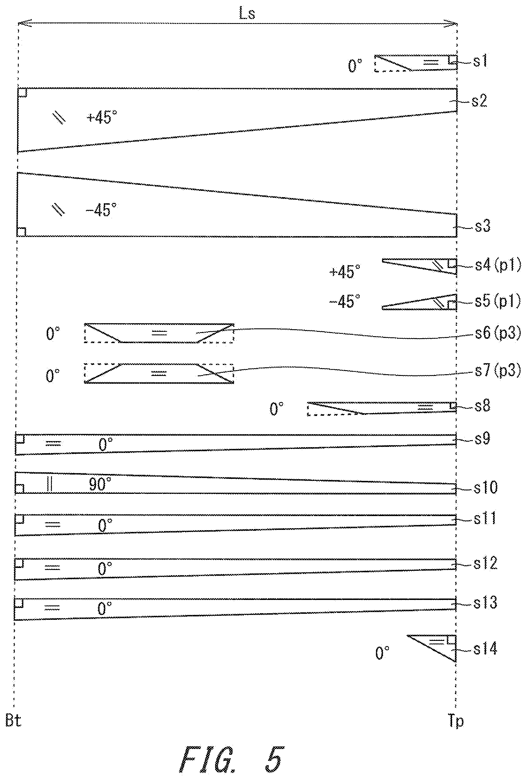
[0025] FIG. 2 is a developed view of prepreg sheets constituting the shaft 6. FIG. 2 shows the sheets constituting the shaft 6. The shaft 6 is constituted by the plurality of sheets. In the embodiment of FIG. 2, the shaft 6 is constituted by 14 sheets. The shaft 6 includes a first sheet s1 to a fourteenth sheet s14. The developed view shows the sheets constituting the shaft in order from the radial inside of the shaft. The sheets are wound in order from the sheet located on the uppermost side in the developed view. In FIG. 2, the horizontal direction of the figure coincides with the axial direction of the shaft. In FIG. 2, the right side of the figure is the tip side of the shaft. In FIG. 2, the left side of the figure is the butt side of the shaft.
[0026] FIG. 2 shows not only the winding order of the sheets but also the position of each of the sheets in the axial direction. The same holds true for FIG. 5 described later. For example, in FIG. 2, an end of the sheet s1 is located at the tip end Tp.
[0027] The shaft 6 includes a straight layer, a bias layer, and a hoop layer. An orientation angle of the fibers (hereinafter referred to as fiber orientation angle) is described for each of the sheets in FIG. 2. A sheet described as "0.degree." is a straight sheet. The straight sheet forms the straight layer.
[0028] The straight layer is a layer in which the fiber orientation angle is substantially set to 0.degree. with respect to the axial direction. Usually, the fiber orientation may not completely be parallel to the shaft axial direction due to an error in winding, for example. In the straight layer, an absolute angle of the fiber orientation angle with respect to the shaft axial direction is less than or equal to 10.degree.. The absolute angle means an absolute value of an angle (fiber orientation angle) formed between the shaft axis line and the orientation of fibers. That is, "the absolute angle is less than or equal to 10.degree." means that "the fiber orientation angle is -10 degrees or greater and +10 degrees or less".
[0029] In the embodiment of FIG. 2, sheets (straight sheets) that form straight layers are the sheet s1, the sheet s8, the sheet s9, the sheet s11, the sheet s12, the sheet s13 and the sheet s14. The straight layers make a great contribution to flexural rigidity and flexural strength.
[0030] The bias layer is a layer in which the fiber orientation is substantially inclined with respect to the axial direction. The bias layer makes a great contribution to torsional rigidity and torsional strength. Preferably, bias layers are constituted by a pair of two sheets (herein after referred to as a sheet pair) in which fiber orientation angles of the respective sheets are inclined inversely to each other. Preferably, the sheet pair includes: a layer having a fiber orientation angle of greater than or equal to -60.degree. and less than or equal to -30.degree.; and a layer having a fiber orientation angle of greater than or equal to 30.degree. and less than or equal to 60.degree.. That is, the absolute angle in the bias layers is preferably greater than or equal to 30.degree. and less than or equal to 60.degree..
[0031] In the shaft 6, sheets (bias sheets) that form the bias layers are the sheet s2, the sheet s3, the sheet s4, the sheet s5, the sheet s6, and the sheet s7. The sheet s2 and the sheet s3 constitute a sheet pair (a first sheet pair). The sheet s4 and the sheet s5 constitute a sheet pair (a second sheet pair). The sheet s6 and the sheet s7 constitute a sheet pair (a third sheet pair). Each sheet pair is wound in a state where the sheets constituting the sheet pair are stuck together. The shaft 6 includes a plurality of (three) sheet pairs.
[0032] In FIG. 2, the fiber orientation angle is described for each sheet. The plus sign (+) and minus sign (-) used with the fiber orientation angle indicate inclined direction of the fibers. A sheet having a plus fiber orientation angle and a sheet having a minus fiber orientation angle are combined in each sheet pair. In each sheet pair, fibers in respective sheets are inclined inversely to each other.
[0033] The hoop layer is a layer that is disposed so that the fiber orientation substantially coincides with the circumferential direction of the shaft. Preferably, in the hoop layer, the absolute angle of the fiber orientation angle is substantially set to 90.degree. with respect to the shaft axial direction. However, the fiber orientation angle to the shaft axial direction may not be completely set to 90.degree. due to an error in winding, for example. In the hoop layer, the absolute angle of the fiber orientation angle is usually 80.degree. or greater and 90.degree. or less.
[0034] The hoop layer makes a great contribution to crushing rigidity and crushing strength of a shaft. The crushing rigidity is a rigidity against crushing deformation. The crushing deformation is caused by a crushing force that is applied to the shaft inward in the radial direction of the shaft. In a typical crushing deformation, the cross section of the shaft is deformed from a circular shape to an elliptical shape. The crushing strength is a strength against the crushing deformation. The crushing strength can relate to the flexural strength. The flexural deformation can involve the crushing deformation. Particularly when a lightweight shaft having a thin wall is used, the flexural deformation is more likely to involve the crushing deformation. Improvement in the crushing strength can contribute to improvement in the flexural strength.
[0035] In the embodiment of FIG. 2, a prepreg sheet (hoop sheet) that constitutes the hoop layer is the sheet s10. The hoop layer s10 is sandwiched between the straight layer s9 and the straight layer s11.
[0036] For manufacturing the shaft 6 shown in FIG. 2, a united sheet is used. The united sheet is formed by sticking a plurality of sheets together.
[0037] In the embodiment of FIG. 2, four united sheets are used. A first united sheet is the combination of the sheet s2 and the sheet s3. A second united sheet is the combination of the sheet s4 and the sheet s5. A third united sheet is the combination of the sheet s6 and the sheet s7. A fourth united sheet is the combination of the sheet s9, the sheet s10 and the sheet s11.
[0038] As described above, in the present disclosure, the sheets and the layers are classified by the fiber orientation angle. Furthermore, in the present disclosure, the sheets and the layers are classified by their length in the axial direction.
[0039] A layer wholly disposed in the axial direction of the shaft is referred to as a full length layer. A sheet wholly disposed in the axial direction of the shaft is referred to as a full length sheet. The wound full length sheet forms the full length layer. A layer partially disposed in the axial direction of the shaft is referred to as a partial layer. A sheet partially disposed in the axial direction of the shaft is referred to as a partial sheet. The wound partial sheet forms the partial layer.
[0040] A layer that is the bias layer and the full length layer is referred to as a full length bias layer. A layer that is the straight layer and the full length layer is referred to as a full length straight layer. A layer that is the hoop layer and the full length layer is referred to as a full length hoop layer.
[0041] In the embodiment of FIG. 2, the full length bias layers are formed by the sheet s2 and the sheet s3. The full length straight layers are formed by the sheet s9, the sheet s11, the sheet s12, and the sheet s13. The shaft 6 includes the plurality of full length straight layers s9, s11, s12 and s13. The full length hoop layer is formed by the sheet s10. The shaft 6 includes the hoop layer s10 sandwiched between the full length straight layers s9 and s11.
[0042] A layer that is the bias layer and the partial layer is referred to as a partial bias layer. A layer that is the straight layer and the partial layer is referred to as a partial straight layer. A layer that is the hoop layer and the partial layer is referred to as a partial hoop layer.
[0043] In the embodiment of FIG. 2, the partial bias layers are formed by the sheet s4, the sheet s5, the sheet s6 and the sheet s7. The partial straight layers are formed by the sheet s1, the sheet s8 and the sheet s14. A partial hoop layer is not provided.
[0044] The sheet s4 and the sheet s5 are tip partial bias layers p1. The tip partial bias layers p1 are disposed on the tip portion of the shaft 6. One end of each tip partial bias layer p1 is located at the tip end Tp. The sheet s6 and the sheet s7 are intermediate partial bias layers p2. The intermediate partial bias layers p2 are located apart from the tip end Tp and apart from the butt end Bt. The shaft 6 includes the tip partial bias layers p1 and the intermediate partial bias layers p2. Each tip partial bias layer p1 does not overlap each intermediate partial bias layer p2 in the axial direction. The center position of each intermediate partial bias layer p2 in the axial direction is located on the but end Bt side with respect to the center position of the shaft 6 in the axial direction. The shaft 6 does not include a butt partial bias layer.
[0045] A region in the axial direction in which each intermediate partial bias layer p2 is disposed (hereinafter also referred to as the axial directional region of each intermediate partial bias layer p2) includes a point that is located 830 mm apart from the tip end Tp. The axial directional region of each intermediate partial bias layer p2 includes a point that is located 730 mm apart from the tip end Tp.
[0046] Hereinafter, manufacturing processes of the shaft 6 will be schematically described.
[Outline of Manufacturing Processes of Shaft]
(1) Cutting Process
[0047] The prepreg sheets are cut into respective desired shapes in the cutting process. Each of the sheets shown in FIG. 2 is cut out by this process.
[0048] The cutting may be performed by a cutting machine. Alternatively, the cutting may be manually performed. In the manual case, a cutter knife is used, for example.
(2) Sticking Process
[0049] In the sticking process, each united sheet described above is produced by sticking a plurality of sheets together. In the sticking process, heating and/or pressing step(s) may be carried out.
(3) Winding Process
[0050] A mandrel is prepared in the winding process. A typical mandrel is made of a metal. A mold release agent is applied to the mandrel. Furthermore, a resin having tackiness is applied to the mandrel. The resin is also referred to as a tacking resin. The cut sheets are wound around the mandrel. The tacking resin facilitates the application of the end part of a sheet to the mandrel.
[0051] A wound body is obtained in the winding process. The wound body is obtained by winding the prepreg sheets around the outside of the mandrel. For example, the winding is achieved by rolling the object to be wound on a plane. The winding may be manually performed or may be performed by a machine. The machine is referred to as a rolling machine.
(4) Tape Wrapping Process
[0052] A tape is wrapped around the outer peripheral surface of the wound body in the tape wrapping process. The tape is also referred to as a wrapping tape. The wrapping tape is helically wrapped while tension is applied to the tape so that there is no gap between adjacent windings. The tape applies pressure to the wound body. The pressure contributes to the reduction of voids.
(5) Curing Process
[0053] In the curing process, the wound body after being subjected to the tape wrapping is heated. The heating cures the matrix resin. In the curing process, the matrix resin fluidizes temporarily. The fluidization of the matrix resin can eliminate air between the sheets or in each sheet. The fastening force of the wrapping tape accelerates the discharge of the air. The curing provides a cured laminate.
(6) Process of Extracting Mandrel and Process of Removing Wrapping Tape
[0054] The process of extracting the mandrel and the process of removing the wrapping tape are performed after the curing process. The process of removing the wrapping tape is preferably performed after the process of extracting the mandrel.
(7) Process of Cutting Off Both Ends
[0055] Both end portions of the cured laminate are cut off in the process. The cutting off flattens the end face of the tip end Tp and the end face of the butt end Bt.
(8) Polishing Process
[0056] The surface of the cured laminate is polished in the process. Spiral unevenness is present on the surface of the cured laminate as the trace of the wrapping tape. The polishing removes the unevenness to smooth the surface of the cured laminate.
(9) Coating Process
[0057] The cured laminate after the polishing process is subjected to coating.
[0058] The shaft 6 has a flexural rigidity at each position thereof. The flexural rigidity is also referred to as EI. The value of the flexural rigidity is also referred to as EI. In the present disclosure, the unit of EI is "kgfm.sup.2". EI can be measured at predetermined positions in the axial direction.
[0059] FIG. 3 shows the method for measuring EI. As a measuring device, a universal testing machine "model 2020 (maximum load: 500 kg)" produced by Intesco Co., Ltd. can be used. The shaft 6 is supported from below at a first supporting point T1 and at a second supporting point T2. In the state where the shaft 6 is supported, a load F1 is applied at a measurement point T3 from above. The load F1 is applied vertically downward. The distance between the point T1 and the point T2 is 200 mm. The measurement point T3 is a point that divides the distance between the point T1 and the point T2 into two equal parts. The amount of bending (flexure) H when the load F1 is applied is measured. The load F1 is applied by an indenter D1. The tip end of the indenter D1 is a cylindrical surface having a radius of curvature of 5 mm. The downwardly moving speed of the indenter D1 is 5 mm/min. When the load F1 reaches 20 kgf (196 N), the indenter D1 is stopped, and the amount of bending H in this state is measured. The amount of bending H is a distance in the vatical direction between the position of the point T3 before the load F1 is applied and the position of the point T3 when the indenter D1 is stopped. EI is calculated by the following formula:
EI(kgfm.sup.2)=F1.times.L.sup.3/(48.times.H),
where, F1 denotes a maximum load (kgf), L is a distance (m) between the support points, and H is the amount of bending (m). The maximum load F1 is 20 kgf. The distance L between the support points is 0.2 m.
[0060] As the measurement points of EI, the following 10 points are exemplified. [0061] (Measurement point 1): a point located 130 mm apart from the tip end Tp [0062] (Measurement point 2): a point located 230 mm apart from the tip end Tp [0063] (Measurement point 3): a point located 330 mm apart from the tip end Tp [0064] (Measurement point 4): a point located 430 mm apart from the tip end Tp [0065] (Measurement point 5): a point located 530 mm apart from the tip end Tp [0066] (Measurement point 6): a point located 630 mm apart from the tip end Tp [0067] (Measurement point 7): a point located 730 mm apart from the tip end Tp [0068] (Measurement point 8): a point located 830 mm apart from the tip end Tp [0069] (Measurement point 9): a point located 930 mm apart from the tip end Tp [0070] (Measurement point 10): a point located 1030 mm apart from the tip end Tp It should be noted that the distances from the tip end Tp for the measurement points are measured in the axial direction. These distances are measured from the tip end Tp toward the butt end Bt.
[0071] In the present disclosure, EI at the measurement point 1 is denoted by E1. EI at the measurement point 2 is denoted by E2. EI at the measurement point 3 is denoted by E3. EI at the measurement point 4 is denoted by E4. EI at the measurement point 5 is denoted by E5. EI at the measurement point 6 is denoted by E6. EI at the measurement point 7 is denoted by E7. EI at the measurement point 8 is denoted by E8. EI at the measurement point 9 is denoted by E9. EI at the measurement point 10 is denoted by E10. The unit of E1 to E10 is kgfm.sup.2. For specifying the values of E1 to E10, the values can be rounded off to the first decimal place.
[0072] FIG. 4 shows a graph on an orthogonal coordinate system having an x-axis that represents a distance (mm) from the tip end and a y-axis that represents a flexural rigidity (kgfm.sup.2). FIG. 4 is a graph showing Example 1 explained below. In this graph, the following 10 points having respective coordinates (x, y) are plotted. [0073] Point (130, E1) [0074] Point (230, E2) [0075] Point (330, E3) [0076] Point (430, E4) [0077] Point (530, E5) [0078] Point (630, E6) [0079] Point (730, E7) [0080] Point (830, E8) [0081] Point (930, E9) [0082] Point (1030, E10)
[0083] For the sake of easy explanation, the point (130, E1) is also referred to as a point E1. The point (230, E2) is also referred to as a point E2. The point (330, E3) is also referred to as a point E3. The point (430, E4) is also referred to as a point E4. The point (530, E5) is also referred to as a point E5. The point (630, E6) is also referred to as a point E6. The point (730, E7) is also referred to as a point E7. The point (830, E8) is also referred to as a point E8. The point (930, E9) is also referred to as a point E9. The point (1030, E10) is also referred to as a point E10.
[0084] In this graph, the formula of a straight line that passes through the point (230, E2) and the point (630, E6) is represented by "y=ax+b". This straight line shows a tendency of the overall rigidity distribution of the shaft. In FIG. 4, the straight line is shown with a dashed line. This straight line is also referred to as L1. In the present embodiment, "a" is 0.0052 and "b" is 1.1.
[0085] The straight line L1 can vary from shaft to shaft. The straight line L1 can be adjusted based on characteristics (e.g., head speed) of a golfer, for example. By specifying relative values of the straight line L1, properties suitable to each shaft can be specified. The gradient "a" of the straight line L1 can be adjusted by a taper ratio of the shaft, for example. The y-intercept "b" of the straight line L1 can be adjusted by the overall wall thickness of the shaft (e.g., the thickness of the full length straight layer(s)), for example. When the flexural rigidity on the whole shaft is changed, the value of "b" can be changed.
[0086] From the viewpoint of not reducing advantageous effects brought by E1 and E8, the gradient "a" of the straight line L1 is preferably great. The gradient "a" is preferably greater than or equal to 0.003, more preferably greater than or equal to 0.004, and still more preferably greater than or equal to 0.005. An excessively great gradient "a" can lead to an excessively small E1 and/or excessively great E8. From this viewpoint, the gradient "a" is preferably less than or equal to 0.008, more preferably less than or equal to 0.007, and still more preferably less than or equal to 0.006.
[0087] When the overall flexural rigidity of a shaft is excessively great, the shaft can become too rigid even for advanced golfers. Such a shaft having an excessively great overall flexural rigidity is difficult to swing and gives a bad feeling to the golfer. From this viewpoint, the y-intercept "b" of the straight line L1 is less than or equal to 3.0, more preferably less than or equal to 2.0, and still more preferably less than or equal to 1.5. When the overall flexural rigidity of a shaft is excessively small, the shaft can become too flexible even for golfers lacking strength. Such a shaft having an excessively small overall flexural rigidity is difficult to swing and gives a bad feeling to the golfer. From this viewpoint, the y-intercept "b" of the straight line L1 is preferably greater than or equal to -1.0, more preferably greater than or equal to 0.0, and still more preferably greater than or equal to 0.5.
[0088] In the embodiment of FIG. 4, the point E1 is positioned higher than the straight line L1. That is, E1 is greater than (130a+b). The point E3 is positioned lower than the straight line L1. That is, E3 is lower than (330a+b). The point E4 is positioned lower than the straight line L1. That is, E4 is lower than (430a+b). The point E5 is positioned lower than the straight line L1. That is, E5 is lower than (530a+b). The point E7 is positioned higher than the straight line L1. That is, E7 is greater than (730a+b). The point E8 is positioned higher than the straight line L1. That is, E8 is greater than (830a+b). The point E9 is positioned lower than the straight line L1. That is, E9 is lower than (930a+b). The point E10 is positioned lower than the straight line L1. That is, E10 is lower than (1030a+b).
[0089] A portion ranging from the point E3 to the point E5 which constitutes a large part of the intermediate portion of the shaft is positioned lower than the straight line L1. Further, a portion ranging from the point E2 to the point E6 (exclusive) is positioned lower than the straight line L1. These structures ensure an appropriate overall bending of the shaft. The head speed can be improved by the synergistic effect of this overall bending and an accelerated motion of the tip portion of the shaft.
[0090] The point E7 is positioned farther from the straight line L1 as compared to the positional relationship between the point E1 and the straight line L1. |E7-(730a+b)| is greater than |E1-(130a+b)|. The point E7 is positioned farther from the straight line L1 as compared to the positional relationship between the point E3 and the straight line L1. |E7-(730a+b)| is greater than |E3-(330a+b)|. The point E7 is positioned farther from the straight line L1 as compared to the positional relationship between the point E4 and the straight line L1. |E7-(730a+b)| is greater than |E4-(430a+b)|. The point E7 is positioned farther from the straight line L1 as compared to the positional relationship between the point E5 and the straight line L1. |E7-(730a+b)| is greater than |E5-(530a+b)|. The point E7 is positioned farther from the straight line L1 as compared to the positional relationship between the point E9 and the straight line L1. |E7-(730a+b)| is greater than |E9-(930a+b)|. The point E10 is positioned farther from the straight line L1 as compared to the positional relationship between the point E7 and the straight line L1. |E10-(1030a+b)| is greater than |E7-(730a+b)|.
[0091] Such an E7 higher than the straight line L1 can further improve advantageous effects brought by E8.
[0092] The point E8 is positioned farther from the straight line L1 as compared to the positional relationship between the point E1 and the straight line L1. |E8-(830a+b)| is greater than |E1-(130a+b)|. The point E8 is positioned farther from the straight line L1 as compared to the positional relationship between the point E3 and the straight line L1. |E8-(830a+b)| is greater than |E3-(330a+b)|. The point E8 is positioned farther from the straight line L1 as compared to the positional relationship between the point E4 and the straight line L1. |E8-(830a+b)| is greater than |E4-(430a+b)|. The point E8 is positioned farther from the straight line L1 as compared to the positional relationship between the point E5 and the straight line L1. |E8-(830a+b)| is greater than |E5-(530a+b)|. The point E8 is positioned farther from the straight line L1 as compared to the positional relationship between the point E9 and the straight line L1. |E8-(830a+b)| is greater than |E9-(930a+b)|. The point E10 is positioned farther from the straight line L1 as compared to the positional relationship between the point E8 and the straight line L1. |E10-(1030a+b)| is greater than |E8-(830a+b)|.
[0093] It should be noted that the symbol ".parallel." denotes an absolute value. For example, |E7-(730a+b)| means the absolute value of [E7-(730a+b)].
[0094] A greater ratio (E8/E1) can improve the golfer's feeling and enable the tip portion of the shaft to provide an improved kick to a golf ball (kick means an improved bounce brought by the behavior of the shaft). The improved kick increases flight distance. From this viewpoint, the ratio (E8/E1) is preferably greater than or equal to 2.0, more preferably greater than or equal to 2.4, and still more preferably greater than or equal to 2.8. An excessively great ratio (E8/E1) leads to a too flexible E1 and/or too rigid E8, which reduces the above-described advantageous effects. From this viewpoint, the ratio (E8/E1) is preferably less than or equal to 7.0, more preferably less than or equal to 6.0, still more preferably less than or equal to 5.0, and yet still more preferably less than or equal to 4.0.
[0095] An excessively great E1 causes difficulty in swinging of the shaft, which also reduces the directional stability of hit balls. A lower E1 allows a golfer to easily feel the bending of the shaft, which improves the feeling of the shaft. Such a lower E1 also accelerates the speed of the tip portion of the shaft, whereby the tip portion can provide an improved kick to a golf ball. From these viewpoints, E1 is preferably less than or equal to 2.5 (kgfm.sup.2), more preferably less than or equal to 2.3 (kgfm.sup.2), and still more preferably less than or equal to 2.1 (kgfm.sup.2). An excessively small E1 leads to a flexible tip portion of the shaft, which reduces the stability of the shaft at impact and the directional stability of hit balls. Such an excessively small E1 also causes an insufficient recovery from bending of the shaft, which hampers the acceleration of the speed of the tip portion of the shaft ("recovery from bending" is a phenomenon in which a shaft that is bent during downswing returns to an unbent state). From these viewpoints, E1 is preferably greater than or equal to 1.5 (kgfm.sup.2), more preferably greater than or equal to 1.7 (kgfm.sup.2), and still more preferably greater than or equal to 1.9 (kgfm.sup.2).
[0096] An excessively small E8 leads to an improper recovery from bending, which reduces the head speed. A greater E8 increases the stability of the shaft and leads to an excellent directional stability of hit balls. Such a greater E8 also provides the golfer with an improved feeling of load applied by the bending of the shaft at immediately before the impact. From this viewpoint, E8 is preferably greater than or equal to 5.0 (kgfm.sup.2), more preferably greater than or equal to 5.3 (kgfm.sup.2), and still more preferably greater than or equal to 5.6 (kgfm.sup.2). An excessively great E8 makes a gripped area of the shaft excessively rigid, which gives a worse feeling to the golfer and reduces the head speed. From this viewpoint, E8 is preferably less than or equal to 6.5 (kgfm.sup.2), more preferably less than or equal to 6.2 (kgfm.sup.2), and still more preferably less than or equal to 5.9 (kgfm.sup.2).
[0097] The shaft 6 satisfies the following relationship R1:
(130a+b)<E1.ltoreq.(130a+b+0.5) (R1)
[0098] Setting E1 to be greater than (130a+b) enhances the stability of the shaft at impact, which leads to an excellent directional stability of hit balls. An excessively small E1 causes an insufficient recovery from bending, which reduces the acceleration of the speed of the tip portion of the shaft. From this viewpoint, E1 is preferably greater than (130a+b), more preferably greater than or equal to (130+b+0.1), and still more preferably greater than or equal to (130a+b+0.2). An excessively great E1 makes the shaft difficult to swing, which reduces the directional stability of hit balls. When E1 is less than or equal to (130a+b+0.5), the speed of the tip portion of the shaft is accelerated, whereby the tip portion provides an excellent kick to a golf ball. From these viewpoints, E1 is preferably less than or equal to (130a+b+0.5), more preferably less than or equal to (130a+b+0.4), and still more preferably less than or equal to (130a+b+0.3).
[0099] As described above, the shaft 6 includes the tip partial bias layers p1 (see FIG. 2). A region in the axial directional in which each tip partial bias layer p1 is disposed (hereinafter also referred to as the axial directional region of each tip partial bias layer p1) includes the point E1. Since the tip partial bias layers p1 are included among tip partial layers, E1 is prevented from becoming excessively great. The above relationship R1 can be easily achieved by the tip partial bias layers p1. Each tip partial bias layer p1 contributes to achievement of the relationship R1 regarding the flexural rigidity while increasing the torsional rigidity of the tip portion of the shaft and enhancing the directional stability of hit balls. From the viewpoint of obtaining a proper E1, the length of each tip partial bias layer p1 in the axial direction is preferably greater than or equal to 130 mm, still more preferably greater than or equal to 140 mm, and yet still more preferably greater than or equal to 150 mm. From the viewpoint of obtaining a proper E1, the length of each tip partial bias layer p1 in the axial direction is preferably less than or equal to 300 mm, more preferably less than or equal to 260 mm, and still more preferably less than or equal to 220 mm.
[0100] The shaft 6 satisfies the following relationship R8. The shaft 6 satisfies the following relationship R81.
(830a+b)<E8.ltoreq.(830a+b+1.0) (R8)
(830a+b+0.5).ltoreq.E8.ltoreq.(830a+b+1.0) (R81)
[0101] When E8 is excessively small, a proper recovery from bending cannot be obtained, which reduces the head speed. Setting E8 to be greater than (830a+b) increases the stability of the shaft during a swing, which enhances the directional stability of hit balls. Such a greater E8 also provides the golfer with an improved feeling of load applied by the bending of the shaft at immediately before the impact. From these viewpoints, E8 is preferably greater than or equal to (830a+b+0.1), more preferably greater than or equal to (830a+b+0.3), and still more preferably greater than or equal to (830a+b+0.5). An excessively great E8 makes the gripped area of the shaft excessively rigid, which gives a worse feeling to the golfer. Such an excessively great E8 also makes the shaft difficult to swing, which reduces the head speed and the directional stability of hit balls. From these viewpoints, E8 is preferably less than or equal to (830a+b+1.0), more preferably less than or equal to (830a+b+0.9), and still more preferably less than or equal to (830a+b+0.8).
[0102] As described above, the straight line L1 shows the tendency of the overall flexural rigidity distribution of the shaft. By specifying relative values of the straight line L1, properties suitable to each shaft can be specified. From this viewpoint, the points E3 to E5 are preferably positioned close to the straight line L1. Specifically, the points E3 to E5 as explained below are preferable.
[0103] The point E3 preferably satisfies the following relationship R3, and more preferably satisfies the following relationship R31.
(330a+b-0.2)<E3.ltoreq.(330a+b+0.2) (R3)
(330a+b-0.1)<E3.ltoreq.(330a+b+0.1) (R31)
[0104] The point E4 preferably satisfies the following relationship R4, and more preferably satisfies the following relationship R41.
(430a+b-0.2)<E4.ltoreq.(430a+b+0.2) (R4)
(430a+b-0.1)<E4.ltoreq.(430a+b+0.1) (R41)
[0105] The point E5 preferably satisfies the following relationship R5, and more preferably satisfies the following relationship R51.
(530a+b-0.2)<E5.ltoreq.(530a+b+0.2) (R5)
(530a+b-0.1)<E5.ltoreq.(530a+b+0.1) (R51)
[0106] Thus, in the embodiment of FIG. 4, the flexural rigidity at the point E8 is higher than the straight line L1. A portion at and near the point E8 is selectively made rigid relative to the straight line L1, which accelerates the speed the tip portion of the shaft to increase the head speed, and enhances the stability of the shaft during a swing, which can provide the golfer with the feeling of the load that is kept until the shaft reaches impact.
[0107] E9 is positioned inside the grip. For this reason, E9 has a less influence on the stability of swing. However, a lower E9 improves the absorbability of vibration felt by golfer's hands, which can improve the feeling of the shaft. From these viewpoints, E9 is preferably less than or equal to (930a+b-0.1), more preferably less than or equal to (930a+b-0.2), and still more preferably less than or equal to (930a+b-0.3). A sharp decrease from E8 to E9 leads to stress concentration, which can reduce the strength of the shaft. From this viewpoint, E9 is preferably greater than or equal to (930a+b-1.0), more preferably greater than or equal to (930a+b-0.8), and still more preferably greater than or equal to (930a+b-0.6).
[0108] E10 is positioned inside the grip. E10 has a lesser influence on the stability of swing than E9. However, a lower E10 improves the absorbability of vibration felt by golfer's hands, which can improve the feeling of the shaft. From these viewpoints, E10 is preferably less than or equal to (1030a+b-0.6), more preferably less than or equal to (1030a+b-0.7), and still more preferably less than or equal to (1030a+b-0.8). A sharp decrease from E8 to E10 leads to stress concentration, which can reduce the strength of the shaft. From this viewpoint, E10 is preferably greater than or equal to (1030a+b-1.8), more preferably greater than or equal to (1030a+b-1.6), and still more preferably greater than or equal to (1030a+b-1.4).
[0109] From the viewpoint of enhancing the absorbability of vibration while obtaining the advantageous effects brought by E8, E10 is preferably lower than E8, and E10 is preferably lower than E9.
[0110] As shown in FIG. 2, the shaft 6 includes the sheet s6 and the sheet s7 as intermediate partial layers. The intermediate partial layers s6 and s7 are located apart from the tip end Tp and apart from the butt end Bt. A region in the axial direction in which the intermediate partial layers s6 and s7 are disposed (hereinafter also referred to as the axial directional region of the intermediate partial layers s6 and s7) includes a point that is located 830 mm apart from the tip end Tp. The axial directional region of the intermediate partial layers s6 and s7 includes a point that is located 730 mm apart from the tip end Tp. In the embodiment of FIG. 2, the number of sheets constituting the intermediate partial layers is two. The number of sheet(s) constituting the intermediate partial layer(s) may be one, or may be three or more, instead of two. The intermediate partial layers s6 and s7 partially increase the flexural rigidity of the shaft. The intermediate partial layers s6 and s7 contribute to the formation of an upwardly protruded portion (hereinafter also referred to as a "rigidity prominent portion") relative to the straight line L1 at and near the point E8 in the graph of FIG. 4. The intermediate partial layer(s) contributes to increase in [E8-(830a+b)].
[0111] Orientation of carbon fibers in the intermediate partial layers s6 and s7 are inclined with respect to the axial direction of the shaft. That is, the intermediate partial layers s6 and s7 are intermediate partial bias layers p2. Since the intermediate partial layers s6 and s7 are the intermediate partial bias layers p2, the flexural rigidity of the rigidity prominent portion is prevented from becoming excessively great. That is, the intermediate partial bias layers p2 make [E8-(830a+b)] a proper value. In addition, by using the intermediate partial bias layers p2, the rigidity of the rigidity prominent portion does not become excessively great even when the length of the intermediate partial layers in the axial directional is made longer to a certain extent. This structure allows the rigidity prominent portion to gradually change its rigidity, which can alleviate stress concentrations at the ends of the rigidity prominent portion.
[0112] When the absolute angle of the fiber orientation angle of the intermediate partial layers (intermediate partial bias layers) is excessively small, [E8-(830a+b)] tends to become higher than its proper value. From this viewpoint, the absolute angle of the fiber orientation angle of the intermediate partial layers (intermediate partial bias layers) is preferably greater than or equal to 20.degree., more preferably greater than or equal to 30.degree., and still more preferably greater than or equal to 40.degree.. When the absolute angle of the fiber orientation angle of the intermediate partial layers (intermediate partial bias layers) is excessively great, [E8-(830a+b)] tends to become lower than its proper value. From this viewpoint, the absolute angle of the fiber orientation angle of the intermediate partial layers (intermediate partial bias layers) is preferably less than or equal to 70.degree., more preferably less than or equal to 60.degree., and still more preferably less than or equal to 50.degree..
[0113] From the viewpoint of appropriately increasing E8, a length Lm (see FIG. 2) of the intermediate partial layers in the axial direction is preferably greater than or equal to 250 mm, more preferably greater than or equal to 300 mm, and still more preferably greater than or equal to 350 mm. From the viewpoint of obtaining proper values of E6 and E9, the length Lm is preferably less than or equal to 550 mm, more preferably less than or equal to 500 mm, and still more preferably less than or equal to 450 mm.
[0114] FIG. 5 is a developed view of prepreg sheets that constitute a shaft according to a second embodiment. The embodiment of FIG. 5 is the same as the embodiment of FIG. 2, except that intermediate partial layers s6 and s7 are intermediate partial straight layers p3, not intermediate partial bias layers p2. In the embodiment of FIG. 5, the absolute angle of the fiber orientation angle of the intermediate partial layers is 0.degree.. In contrast, the absolute angle of the fiber orientation angle of the intermediate partial layers is 45.degree. in the embodiment of FIG. 2.
[0115] When the intermediate partial layers are the intermediate partial straight layers, the flexural rigidity of the rigidity prominent portion can be excessively great. From the viewpoint of obtaining a proper value of [E8-(830a+b)], the intermediate partial layer(s) is/are preferably intermediate partial bias layer(s).
[0116] In a table shown below, the embodiment of FIG. 5 is shown as Comparative Examples (Comparative Example 2 and Comparative Example 5). The embodiment of FIG. 5, however, can also be an Example.
[0117] For carrying out the measurement of E10, the length Ls of the shaft needs to be greater than or equal to 1030 mm. As understood from the measuring method of EI shown in FIG. 3, for measuring E10, the shaft needs to extends further 100 mm toward the butt end from a point 1030 mm apart from the tip end Tp. However, the butt end portion of the shaft can be cut off after the measurement of E10. From the viewpoint of the measurement of E10, the length Ls of the shaft is preferably greater than or equal to 1030 mm, more preferably greater than or equal to 1080 mm, still more preferably greater than or equal to 1130 mm, and yet still more preferably greater than or equal to 1140 mm. From the viewpoint of restriction on club length by golf rules, the length Ls of the shaft is preferably less than or equal to 1210 mm, more preferably less than or equal to 1200 mm, and still more preferably less than or equal to 1190 mm.
EXAMPLES
Example 1
[0118] A shaft was produced in accordance with the above explained manufacturing processes of the shaft. Constitution of sheets in the shaft was as shown in FIG. 2. The length Ls of the shaft was 1143 mm. A driver head and a grip were attached to the produced shaft to obtain a golf club.
Examples 2 to 6 and Comparative Examples 1 to 6
[0119] Golf clubs of Examples 2 to 6 and Comparative Examples 1 to 6 were obtained in the same manner as in Example 1 except that specifications as shown in Table 1 and Table 2 were adopted for respective clubs. Constitution of sheets and prepreg material were changed for each shaft to adjust values of E1 to E10.
<Measurement of Flexural Rigidity ET>
[0120] In accordance with the above explained method shown in FIG. 3, EI values at the measurement points E1 to E10 were measured for each club. The measured values for each club are shown in Table 1 and Table 2.
<Measurement of Flight Distance>
[0121] Five golfers who swing a driver at a head speed of 40 m/s or greater and have a handicap from 0 to 10 each hit a ball five times using each of the clubs to measure a flight distance for each shot. The flight distance is a distance to where a ball hit by the club finally arrives, and includes a distance by which the ball runs on the ground. The flight distance shown in Table 1 and Table 2 below is an average value of measured values per club.
<Directional Stability of Hit Balls>
[0122] The directional stability of the hit ball was also measured in each of the above performed shots for measuring flight distances. A distance between the final arrival point of each hit ball and a line that passes through the initial position of the ball to be hit and a target position was measured. This distance was regarded as a plus value, irrespective of whether the hit ball flied rightward or leftward relative to the target direction. The average values of the distances of respective clubs were evaluated (classified) on a scale of 1 to 5, where the score 1 is the highest average value and the score 5 is the lowest average value. The higher the score is, the higher the directional stability of hit balls is. The evaluated scores are shown in below Table 1 and Table 2.
<Head Speed>
[0123] The head speed was also measured in each of the above performed shots for measuring flight distances. The head speed shown in Table 1 and Table 2 are average values for respective clubs.
<Feeling>
[0124] Feeling was also measured in each of the above performed shots for measuring flight distances. The feeling at impact for each shot was evaluated on a scale of one to five by each golfer. The higher the score is, the better the feeling is. The average values of the evaluated scores for respective clubs are shown in below Table 1 and Table 2.
TABLE-US-00001 TABLE 1 Specifications and evaluation results for Examples Unit Ex. 1 Ex. 2 Ex. 3 Ex. 4 Ex. 5 Ex. 6 E8/E1 -- 2.92 2.87 2.54 3.18 3.25 2.87 E1 kgf m.sup.2 1.97 2.01 2.27 1.97 1.97 1.97 E8 kgf m.sup.2 5.76 5.76 5.76 6.26 6.41 5.66 E1 - (130a + b) kgf m.sup.2 0.19 0.23 0.49 0.19 0.19 0.19 E8 - (830a + b) kgf m.sup.2 0.34 0.34 0.34 0.84 0.99 0.24 E9 - (930a + b) kgf m.sup.2 -0.14 -0.13 -0.12 -0.14 -0.14 -0.14 E10 - (1030a + b) kgf m.sup.2 -0.83 -0.83 -0.83 -0.73 -0.63 -0.93 Gradient ''a'' of -- 0.0052 0.0052 0.0052 0.0052 0.0052 0.0052 straight line L1 Y-intercept ''b'' of -- 1.1 1.1 1.1 1.1 1.1 1.1 straight line L1 Absolute angle of degree 45 45 45 45 45 45 fiber orientation angle of intermediate partial layer(s) Flight distance yard 272 271 270 271 270 269 Directional stability of -- 5.0 4.9 4.8 4.8 4.9 4.5 hit balls (on a scale of 1 to 5) Head speed m/s 45.5 45.2 45.1 45.1 45.2 44.9 Feeling -- 5.0 4.8 4.7 4.8 4.9 4.6 (on a scale of 1 to 5)
TABLE-US-00002 TABLE 2 Specifications and evaluation results for Comparative Examples Comp. Comp. Comp. Comp. Comp. Comp. Unit Ex. 1 Ex. 2 Ex. 3 Ex. 4 Ex. 5 Ex. 6 E8/E1 -- 3.84 2.68 2.38 4.61 3.57 2.15 E1 kgf m.sup.2 1.30 2.78 2.09 1.30 2.09 2.78 E8 kgf m.sup.2 4.97 7.45 4.97 5.97 7.45 5.97 E1 - (130a + b) kgf m.sup.2 -0.48 1.00 0.31 -0.48 0.31 1.00 E8 - (830a + b) kgf m.sup.2 -0.45 2.03 -0.45 0.55 2.03 0.55 E9 - (930a + b) kgf m.sup.2 -0.09 -0.05 -0.07 -0.09 -0.07 -0.05 E10 - (1030a + b) kgf m.sup.2 -1.98 -0.43 -1.98 -0.53 -0.43 -0.53 Gradient ''a'' of -- 0.0052 0.0052 0.0052 0.0052 0.0052 0.0052 straight line L1 Y-intercept ''b'' of -- 1.1 1.1 1.1 1.1 1.1 1.1 straight line L1 Absolute angle of degree 45 0 45 45 0 45 fiber orientation angle of intermediate partial layer(s) Flight distance yard 261 255 265 266 268 256 Directional stability of -- 3.3 4.1 4.4 3.3 4.4 4.1 hit balls (on a scale of 1 to 5) Head speed m/s 42.6 42.1 43.8 43.2 44.1 42.8 Feeling -- 3.3 3.7 3.4 3.4 4.3 3.8 (on a scale of 1 to 5)
[0125] As shown in Table 1 and Table 2, Examples are highly evaluated as compared with Comparative Examples.
[0126] The following clauses are a part of invention included in the present disclosure.
[Clause 1]
[0127] A golf club shaft including:
[0128] a tip end;
[0129] a butt end;
[0130] a flexural rigidity E1 at a point located 130 mm apart from the tip end;
[0131] a flexural rigidity E2 at a point located 230 mm apart from the tip end;
[0132] a flexural rigidity E3 at a point located 330 mm apart from the tip end;
[0133] a flexural rigidity E4 at a point located 430 mm apart from the tip end;
[0134] a flexural rigidity E5 at a point located 530 mm apart from the tip end;
[0135] a flexural rigidity E6 at a point located 630 mm apart from the tip end;
[0136] a flexural rigidity E7 at a point located 730 mm apart from the tip end;
[0137] a flexural rigidity E8 at a point located 830 mm apart from the tip end;
[0138] a flexural rigidity E9 at a point located 930 mm apart from the tip end; and
[0139] a flexural rigidity E10 at a point located 1030 mm apart from the tip end, wherein
[0140] a ratio (E8/E1) is greater than or equal to 2 and less than or equal to 7,
[0141] the flexural rigidity E1 is less than or equal to 2.5 (kgfm.sup.2),
[0142] the flexural rigidity E8 is greater than or equal to 5.0 (kgfm.sup.2),
[0143] when a formula of a straight line that passes through a point (230, E2) and a point (630, E6) plotted in a graph on an orthogonal coordinate system having an x-axis that represents a distance (mm) from the tip end and a y-axis that represents a flexural rigidity (kgfm.sup.2) is indicated by y=ax+b, the golf club shaft satisfies the following relationships R1 and R8:
(130a+b)<E1.ltoreq.(130a+b+0.5) (R1), and
(830a+b)<E8.ltoreq.(830a+b+1.0) (R8).
[Clause 2]
[0144] The golf club shaft according to clause 1, wherein the golf club shaft further satisfies the following relationship R81:
(830a+b+0.3).ltoreq.E8.ltoreq.(830a+b+1.0) (R81).
[Clause 3]
[0145] The golf club shaft according to clause 1 or 2, wherein
[0146] the flexural rigidity E9 is less than or equal to (930a+b-0.1).
[Clause 4]
[0147] The golf club shaft according to any one of clauses 1 to 3, wherein
[0148] the flexural rigidity E10 is less than or equal to (1030a+b-0.6).
[Clause 5]
[0149] The golf club shaft according to any one of clauses 1 to 4, wherein
[0150] the golf club shaft further satisfies the following relationships R3, R4 and R5:
(330a+b-0.2)<E3.ltoreq.(330a+b+0.2) (R3),
(430a+b-0.2)<E4.ltoreq.(430a+b+0.2) (R4), and
(530a+b-0.2)<E5.ltoreq.(530a+b+0.2) (R5).
[Clause 6]
[0151] The golf club shaft according to any one of clauses 1 to 5, wherein
[0152] the golf club shaft is formed by a plurality of carbon fiber reinforced resin layers,
[0153] the carbon fiber reinforced resin layers include an intermediate partial bias layer that is disposed apart from the tip end and apart from the butt end, and
[0154] an axial directional region in which the intermediate partial bias layer is disposed includes a point 830 mm apart from the tip end.
LIST OF REFERENCE NUMERALS
[0155] 2 Golf club [0156] 4 Head [0157] 6 Shaft [0158] 8 Grip [0159] s1 to s14 Prepreg sheet (layer) [0160] p2 Intermediate partial bias layer (Intermediate partial layer) [0161] p3 Intermediate partial straight layer (Intermediate partial layer) [0162] Bt Butt end [0163] Tp Tip end
[0164] The above descriptions are merely illustrative and various modifications can be made without departing from the principles of the present disclosure.
[0165] The terminology used in the description of the various described embodiments herein is for the purpose of describing particular embodiments only and is not intended to be limiting. The use of the terms "a", "an", "the", and similar referents in the context of throughout this disclosure (especially in the context of the following claims) are to be construed to cover both the singular and the plural, unless otherwise indicated herein or clearly contradicted by context. As used throughout this disclosure, the word "may" is used in a permissive sense (i.e., meaning "having the potential to"), rather than the mandatory sense (i.e., meaning "must"). Similarly, as used throughout this disclosure, the terms "comprising", "having", "including", and "containing" are to be construed as open-ended terms (i.e., meaning "including, but not limited to,") unless otherwise noted.
* * * * *
D00000
D00001
D00002
D00003
D00004
D00005
XML
uspto.report is an independent third-party trademark research tool that is not affiliated, endorsed, or sponsored by the United States Patent and Trademark Office (USPTO) or any other governmental organization. The information provided by uspto.report is based on publicly available data at the time of writing and is intended for informational purposes only.
While we strive to provide accurate and up-to-date information, we do not guarantee the accuracy, completeness, reliability, or suitability of the information displayed on this site. The use of this site is at your own risk. Any reliance you place on such information is therefore strictly at your own risk.
All official trademark data, including owner information, should be verified by visiting the official USPTO website at www.uspto.gov. This site is not intended to replace professional legal advice and should not be used as a substitute for consulting with a legal professional who is knowledgeable about trademark law.