Foldable Treadmill with Furniture Configuration
Tsai; Yu-Lun
U.S. patent application number 17/079794 was filed with the patent office on 2022-04-28 for foldable treadmill with furniture configuration. The applicant listed for this patent is Yu-Lun Tsai. Invention is credited to Yu-Lun Tsai.
| Application Number | 20220126165 17/079794 |
| Document ID | / |
| Family ID | 1000005180208 |
| Filed Date | 2022-04-28 |


| United States Patent Application | 20220126165 |
| Kind Code | A1 |
| Tsai; Yu-Lun | April 28, 2022 |
Foldable Treadmill with Furniture Configuration
Abstract
A foldable treadmill includes a working base, a cover pivotally connected with the working base, a walking belt mounted on the working base, at least two rollers arranged in the walking belt, a support board arranged in the walking belt, two handle units mounted on the working base, and a front support rack mounted on the cover. The working base has two first receiving grooves. The cover has a second receiving groove. The two handle units are removably received in the two first receiving grooves of the working base respectively. Each of the two handle units includes an upright pivotally connected with the working base, and a first handle pivotally connected with the upright. The front support rack is pivotally connected with the cover and received in the second receiving groove of the cover.
| Inventors: | Tsai; Yu-Lun; (Taichung City, TW) | ||||||||||
| Applicant: |
|
||||||||||
|---|---|---|---|---|---|---|---|---|---|---|---|
| Family ID: | 1000005180208 | ||||||||||
| Appl. No.: | 17/079794 | ||||||||||
| Filed: | October 26, 2020 |
| Current U.S. Class: | 1/1 |
| Current CPC Class: | A63B 2210/50 20130101; A63B 22/02 20130101 |
| International Class: | A63B 22/02 20060101 A63B022/02 |
Claims
1. A foldable treadmill comprising: a working base; a cover pivotally connected with the working base; a walking belt mounted on the working base; at least two rollers arranged in the walking belt; a support board arranged in the walking belt; two handle units mounted on the working base; and a front support rack mounted on the cover; wherein: the working base is a platform placed on a plane; the working base has a top provided with two first receiving grooves; the cover has a side pivotally connected with a side of the working base; the cover is pivotable relative to the working base to open or cover the top of the working base; the cover has an inner face provided with a second receiving groove; the walking belt is rotatably mounted on the working base; the two handle units are removably received in the two first receiving grooves of the working base respectively; each of the two handle units includes an upright pivotally connected with the working base, and a first handle pivotally connected with the upright; each of the two handle units is movable relative to the working base; the first handle is movable relative to the upright; the front support rack is pivotally connected with the cover and received in the second receiving groove of the cover; and the front support rack is movable relative to the working base.
2. The foldable treadmill as claimed in claim 1, wherein the front support rack is provided with an electronic instrument.
3. The foldable treadmill as claimed in claim 1, further comprising: a drive motor mounted on the working base; wherein the drive motor drives and rotates the at least two rollers which drives and rotates the walking belt.
4. The foldable treadmill as claimed in claim 1, wherein each of the two handle units is connected with the front support rack by a fastener member.
5. The foldable treadmill as claimed in claim 1, further comprising: two support posts mounted on the working base; wherein: the two support posts are removably received in the two first receiving grooves of the working base respectively; each of the two support posts is pivotally connected with the working base; each of the two support posts is movable relative to the working base; each of the two handle units further includes a second handle telescopically mounted on the first handle; and the second handle of each of the two handle units is connected with one of the two support posts by a fastener member.
Description
BACKGROUND OF THE INVENTION
1. Field of the Invention
[0001] The present invention relates to an exercising apparatus and, more particularly, to a foldable treadmill.
2. Description of the Related Art
[0002] A conventional treadmill comprises a platform, a walking belt mounted on the platform, two rollers arranged in the walking belt, a support board arranged in the walking belt, and a handle mounted on the platform. However, the conventional treadmill has a large volume and cannot be folded, thereby causing inconvenience to the user in storage and transportation. In addition, the conventional treadmill does not have a configuration mating with the interior of the house, thereby decreasing the aesthetic quality of the house. Further, the conventional treadmill does not have a dustproof function so that dirt is easily accumulated on the conventional treadmill.
BRIEF SUMMARY OF THE INVENTION
[0003] The primary objective of the present invention is to provide a foldable treadmill with a furniture configuration.
[0004] In accordance with the present invention, there is provided a foldable treadmill comprising a working base, a cover pivotally connected with the working base, a walking belt mounted on the working base, at least two rollers arranged in the walking belt, a support board arranged in the walking belt, two handle units mounted on the working base, and a front support rack mounted on the cover. The working base is a platform placed on a plane. The working base has a top provided with two first receiving grooves. The cover has a side pivotally connected with a side of the working base. The cover is pivotable relative to the working base to open or cover the top of the working base. The cover has an inner face provided with a second receiving groove. The walking belt is rotatably mounted on the working base. The two handle units are removably received in the two first receiving grooves of the working base respectively. Each of the two handle units includes an upright pivotally connected with the working base, and a first handle pivotally connected with the upright. Each of the two handle units is movable relative to the working base. The first handle is movable relative to the upright. The front support rack is pivotally connected with the cover and received in the second receiving groove of the cover. The front support rack is movable relative to the working base.
[0005] Further benefits and advantages of the present invention will become apparent after a careful reading of the detailed description with appropriate reference to the accompanying drawings.
BRIEF DESCRIPTION OF THE SEVERAL VIEWS OF THE DRAWING(S)
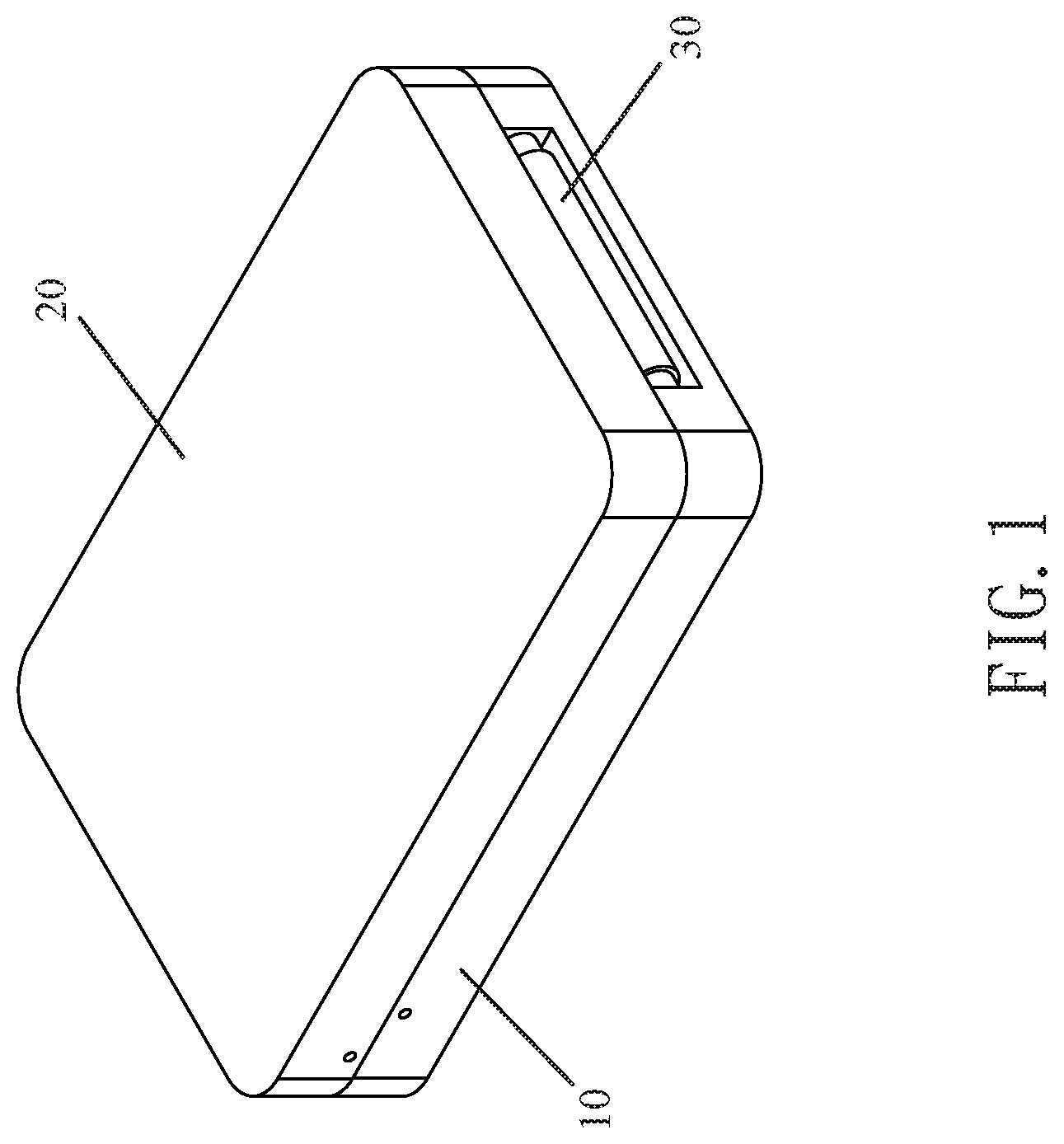
[0006] FIG. 1 is a perspective view of a foldable treadmill in accordance with the first preferred embodiment of the present invention.
[0007] FIG. 2 is a perspective view showing the cover is removed.
[0008] FIG. 3 is a perspective view showing a partially expanded state of the foldable treadmill in accordance with the first preferred embodiment of the present invention.
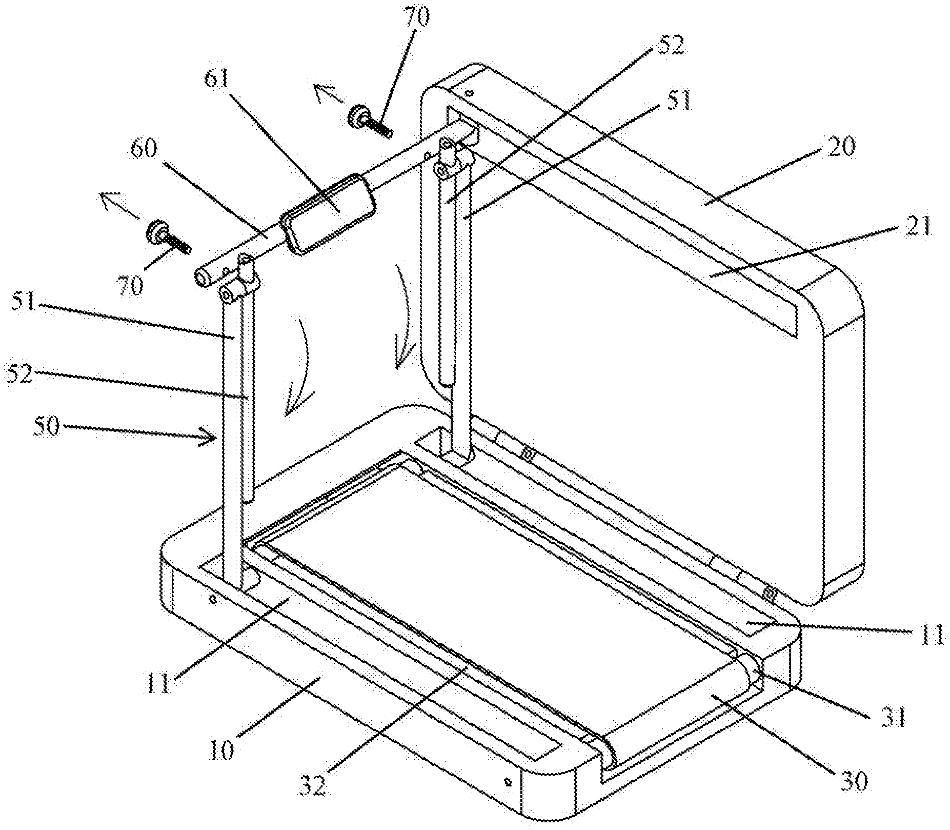
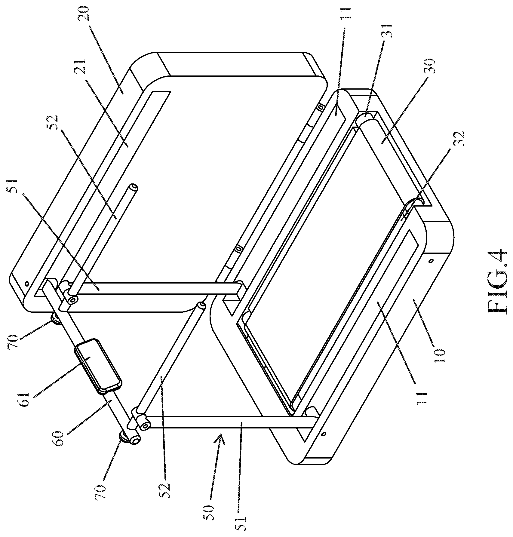
[0009] FIG. 4 is a perspective view showing a fully expanded state of the foldable treadmill in accordance with the first preferred embodiment of the present invention.
[0010] FIG. 5 is a cross-sectional view of the foldable treadmill as shown in FIG. 1.
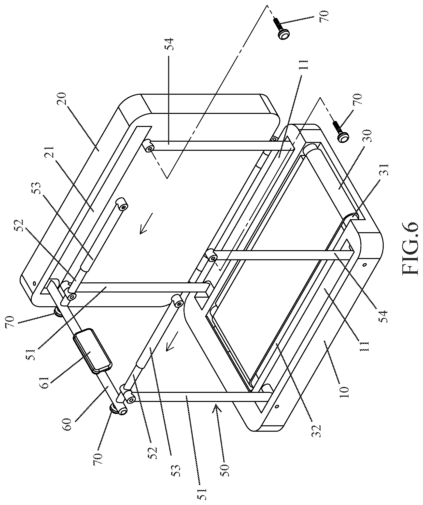
[0011] FIG. 6 is a perspective view showing a partially expanded state of a foldable treadmill in accordance with the second preferred embodiment of the present invention.
[0012] FIG. 7 is a perspective view showing a fully expanded state of the foldable treadmill in accordance with the second preferred embodiment of the present invention.
[0013] FIG. 8 is a perspective view showing a partially folded state of the foldable treadmill in accordance with the second preferred embodiment of the present invention.
[0014] FIG. 9 is a perspective view showing a fully folded state of the foldable treadmill in accordance with the second preferred embodiment of the present invention.
DETAILED DESCRIPTION OF THE INVENTION
[0015] Referring to the drawings and initially to FIGS. 1-5, a foldable treadmill in accordance with the preferred embodiment of the present invention comprises a working base 10, a cover 20 pivotally connected with the working base 10, a walking belt 30 mounted on the working base 10, at least two rollers 31 arranged in the walking belt 30, a support board 32 arranged in the walking belt 30, two handle units 50 mounted on the working base 10, and a front support rack 60 mounted on the cover 20.
[0016] The working base 10 is a platform placed on a plane. The working base 10 has a top provided with two first receiving grooves 11. The two first receiving grooves 11 are arranged at an edge of the working base 10.
[0017] The cover 20 has a side pivotally connected with a side of the working base 10. The cover 20 is pivotable relative to the working base 10 to open or cover the top of the working base 10. The cover 20 has an inner face provided with a second receiving groove 21. Thus, when the cover 20 is pivoted upward and removed from the working base 10, the two first receiving grooves 11 and the second receiving groove 21 are exposed outward.
[0018] The walking belt 30 has an endless shape. The walking belt 30 is rotatably mounted on the working base 10. The at least two rollers 31 and the support board 32 are encompassed by the walking belt 30. The walking belt 30 is driven by the at least two rollers 31 and moved on the support board 32.
[0019] The two handle units 50 are removably received in the two first receiving grooves 11 of the working base 10 respectively. Each of the two handle units 50 includes an upright 51 pivotally connected with the working base 10, and a first handle 52 pivotally connected with the upright 51. Each of the two handle units 50 is movable relative to the working base 10 between a first position as shown in FIG. 2 where the upright 51 and the first handle 52 are folded into and fully received in one of the two first receiving grooves 11 of the working base 10 and a second position as shown in FIG. 3 where the upright 51 and the first handle 52 are expanded outward from one of the two first receiving grooves 11 of the working base 10. The first handle 52 is movable relative to the upright 51 between a first location as shown in FIG. 3 where the first handle 52 is juxtaposed to the upright 51 and a second location as shown in FIG. 4 where the first handle 52 is perpendicular to the upright 51.
[0020] The front support rack 60 is pivotally connected with the cover 20 and received in the second receiving groove 21 of the cover 20. The front support rack 60 is movable relative to the working base 10 between a first position as shown in FIG. 2 where the front support rack 60 is folded into and fully received in the second receiving groove 21 of the cover 20 and a second position as shown in FIG. 3 where the front support rack 60 is expanded outward from the second receiving groove 21 of the cover 20 and is perpendicular to the cover 20.
[0021] In the preferred embodiment of the present invention, the front support rack 60 is provided with an electronic instrument (or control panel) 61.
[0022] In the preferred embodiment of the present invention, the foldable treadmill further comprises a drive motor 40 mounted on the working base 10. The drive motor 40 drives and rotates the at least two rollers 31 which drives and rotates the walking belt 30.
[0023] In the preferred embodiment of the present invention, each of the two handle units 50 is connected with the front support rack 60 by a fastener member 70. Preferably, the fastener member 70 is a screw knob.
[0024] In the preferred embodiment of the present invention, the fastener member 70 extends through the front support rack 60 and is screwed into the first handle 52 of each of the two handle units 50.
[0025] In operation, after the cover 20 is pivoted upward to open the working base 10, the front support rack 60 is moved outward relative to the working base 10 and is expanded outward from the second receiving groove 21 of the cover 20 until the front support rack 60 is perpendicular to the cover 20. Then, each of the two handle units 50 is pivoted and moved upward relative to the working base 10 such that the upright 51 and the first handle 52 are expanded outward from one of the two first receiving grooves 11 of the working base 10 until the upright 51 is disposed at a vertical state. Then, the first handle 52 is pivoted and moved upward relative to the upright 51 until the first handle 52 is perpendicular to the upright 51. Then, the fastener member 70 extends through the front support rack 60 and is screwed into the first handle 52 of each of the two handle units 50. Thus, the first handle 52 of each of the two handle units 50 and the front support rack 60 are secured by the fastener member 70. In such a manner, when the user is walking or running on the walking belt 30, the front support rack 60 or the first handle 52 of each of the two handle units 50 is used to support the user's hands.
[0026] Referring to FIGS. 6-9, the foldable treadmill further comprises two support posts 54 mounted on the working base 10. The two support posts 54 are removably received in the two first receiving grooves 11 of the working base 10 respectively. Each of the two support posts 54 is pivotally connected with the working base 10. Each of the two support posts 54 is movable relative to the working base 10 between a first position as shown in FIG. 8 where each of the two support posts 54 is folded into and fully received in one of the two first receiving grooves 11 of the working base 10 and a second position as shown in FIG. 6 where each of the two support posts 54 is expanded outward from one of the two first receiving grooves 11 of the working base 10 and is perpendicular to the working base 10. Each of the two handle units 50 further includes a second handle 53 telescopically mounted on the first handle 52. The second handle 53 of each of the two handle units 50 is connected with one of the two support posts 54 by the fastener member 70. The fastener member 70 extends through each of the two support posts 54 and is screwed into the second handle 53 of each of the two handle units 50.
[0027] In operation, after the cover 20 is pivoted upward to open the working base 10, the front support rack 60 is moved outward relative to the working base 10 and is expanded outward from the second receiving groove 21 of the cover 20 until the front support rack 60 is perpendicular to the cover 20. Then, each of the two handle units 50 is pivoted and moved upward relative to the working base 10 such that the upright 51 and the first handle 52 are expanded outward from one of the two first receiving grooves 11 of the working base 10 until the upright 51 is disposed at a vertical state. Then, the first handle 52 is pivoted and moved upward relative to the upright 51 until the first handle 52 is perpendicular to the upright 51. Then, the fastener member 70 extends through the front support rack 60 and is screwed into the first handle 52 of each of the two handle units 50. Thus, the first handle 52 of each of the two handle units 50 and the front support rack 60 are secured by the fastener member 70. Then, each of the two support posts 54 is pivoted upward relative to the working base 10 and is expanded outward from one of the two first receiving grooves 11 of the working base 10 until each of the two support posts 54 is disposed at a vertical state. Then, the second handle 53 of each of the two handle units 50 is pulled outward relative to the first handle 52 and is moved to abut one of the two support posts 54. Then, the fastener member 70 extends through each of the two support posts 54 and is screwed into the second handle 53 of each of the two handle units 50 such that each of the two support posts 54 and the second handle 53 of each of the two handle units 50 are secured by the fastener member 70. In such a manner, when the user is walking or running on the walking belt 30, the front support rack 60 or the first handle 52 of each of the two handle units 50 or the second handle 53 of each of the two handle units 50 is used to support the user's hands.
[0028] Accordingly, the foldable treadmill is assembled quickly after the cover 20 is pivoted upward to open the working base 10, such that the foldable treadmill is assembled and operated easily and conveniently. In addition, the foldable treadmill is collapsed and stored easily and occupies a small space when not in use, thereby facilitating packaging, storage and transportation of the foldable treadmill. Further, the cover 20 covers the working base 10 when the foldable treadmill is not in use to provide a dustproof and storage effect. Further, when the foldable treadmill is folded, the foldable treadmill functions as a piece of furniture, such as a cabinet, chair, bed or the like, thereby enhancing the versatility of the foldable treadmill and the aesthetic quality of the house.
[0029] Although the invention has been explained in relation to its preferred embodiment(s) as mentioned above, it is to be understood that many other possible modifications and variations can be made without departing from the scope of the present invention. It is, therefore, contemplated that the appended claim or claims will cover such modifications and variations that fall within the scope of the invention.
* * * * *
D00000
D00001
D00002
D00003
D00004
D00005
D00006
D00007
D00008
D00009
XML
uspto.report is an independent third-party trademark research tool that is not affiliated, endorsed, or sponsored by the United States Patent and Trademark Office (USPTO) or any other governmental organization. The information provided by uspto.report is based on publicly available data at the time of writing and is intended for informational purposes only.
While we strive to provide accurate and up-to-date information, we do not guarantee the accuracy, completeness, reliability, or suitability of the information displayed on this site. The use of this site is at your own risk. Any reliance you place on such information is therefore strictly at your own risk.
All official trademark data, including owner information, should be verified by visiting the official USPTO website at www.uspto.gov. This site is not intended to replace professional legal advice and should not be used as a substitute for consulting with a legal professional who is knowledgeable about trademark law.