Picture Frame Hanger
Willis; David E.
U.S. patent application number 17/512438 was filed with the patent office on 2022-04-28 for picture frame hanger. The applicant listed for this patent is David E. Willis. Invention is credited to David E. Willis.
| Application Number | 20220125223 17/512438 |
| Document ID | / |
| Family ID | 1000005989342 |
| Filed Date | 2022-04-28 |


| United States Patent Application | 20220125223 |
| Kind Code | A1 |
| Willis; David E. | April 28, 2022 |
PICTURE FRAME HANGER
Abstract
A picture frame hanger includes a horizontal level bar. The horizontal level bar has a top leveled surface with a bottom curved edge. A securing tab extends upwards from the top leveled surface and provides an attachment point for a picture frame with standard hanging hardware. The top leveled surface provides a level surface for the standard hanging hardware to rest and the bottom curved edge allows for the rotation of the picture frame hanger and the attached picture frame to level the attached picture frame. A vertical support bar extends downward from the horizontal lever bar and provides a lever arm to counteract the downward force created by the weight of the picture frame to prevent the picture frame hanger and picture frame from tilting forward.
| Inventors: | Willis; David E.; (Aliso Viejo, CA) | ||||||||||
| Applicant: |
|
||||||||||
|---|---|---|---|---|---|---|---|---|---|---|---|
| Family ID: | 1000005989342 | ||||||||||
| Appl. No.: | 17/512438 | ||||||||||
| Filed: | October 27, 2021 |
Related U.S. Patent Documents
| Application Number | Filing Date | Patent Number | ||
|---|---|---|---|---|
| 63106305 | Oct 27, 2020 | |||
| Current U.S. Class: | 1/1 |
| Current CPC Class: | A47G 1/205 20130101; A47G 1/1606 20130101; A47G 1/24 20130101 |
| International Class: | A47G 1/20 20060101 A47G001/20; A47G 1/24 20060101 A47G001/24; A47G 1/16 20060101 A47G001/16 |
Claims
1. A picture frame hanger comprising: a horizontal level bar wherein said horizontal level bar has a top leveled surface and a bottom curved edge; a securing tab centrally formed upon and extending above the top leveled surface of the horizontal level bar; and a vertical support bar centrally formed upon and extending below the bottom curved edge of the horizontal level bar.
2. The picture frame hanger of claim 1 wherein the curved bottom surface further comprises a beveled edge.
3. The picture frame hanger of claim 1 wherein the securing tab provides an attachment point for a picture frame.
4. The picture frame hanger of claim 1 wherein the top leveled surface provides a level surface for picture hanging hardware to rest on and wherein the bottom curved edge allows for the rotation of the picture frame hanger and an attached picture frame to level the attached picture frame.
5. The picture frame hanger of claim 4 wherein the vertical support bar provides a lever arm to counteract the downward force created by the weight of the picture frame.
6. The picture frame hanger of claim 4 wherein the vertical support bar prevents the picture frame hanger and picture frame from tilting forward.
7. The picture frame hanger of claim 1 wherein the securing tab has a thickness less than the horizontal level bar.
8. The picture frame hanger of claim 1 wherein a surface of the securing tab is flush with a surface of the horizontal level bar and is further flush with a surface of the vertical support bar.
9. The picture frame hanger of claim 1 wherein the horizontal level bar has a proximal and distal end.
10. The picture frame hanger of claim 9 wherein the proximal and distal ends of horizontal level bar each further comprise a stop member.
11. The picture frame hanger of claim 9 wherein the proximal and distal ends of horizontal level bar each further comprise a slot frame.
12. A picture frame hanger system comprising: a horizontal level bar wherein said horizontal level bar has a top leveled surface and a bottom curved edge; a securing tab centrally formed upon and extending above the top leveled surface of the horizontal level bar; a vertical support bar centrally formed upon and extending below the bottom curved edge of the horizontal level bar; a picture frame comprising a plurality of elongated picture frame members each having two ends, wherein said picture frame members ends are fixedly attached to form an enclosed area; wherein said picture frame further comprises a transparent panel, a backing panel, a plurality of tab slots and a plurality of tabs, wherein said tab slots are designed to receive said tabs; and wherein at least one of said elongated picture frame members further comprises a securing tab slot designed to receive said securing tab.
Description
FIELD OF INVENTION
[0001] The present invention relates generally to hangers. The present invention relates particularly, though not exclusively, to a picture frame hanger. The present application claims priority to Provisional Patent Application No. 63/106,305 filed on Oct. 27, 2020.
BACKGROUND OF THE INVENTION
[0002] Hanging picture frames on a wall are generally tedious tasks that require an investment in time, tools, effort, and money. To hang a picture frame, a person generally screws a single screw into a wall and attaches the picture from the picture frames supplied wire, keyhole, or saw tooth picture hanger. The person then needs to align the supplied wire, D-rings, or saw tooth picture hanger with the single nail, all the while the person's vision is impeded by the picture frame itself. Once attach the person then levels the picture frame. However, by utilizing the single nail, the nail in conjunction with the provided wire, D-rings, or saw tooth picture hanger acts as a pivot point and picture rotates and swings about the single nail and becomes unleveled. To solve this problem, people often purchase picture frame hanger attachments.
[0003] The picture fame hanger attachments include D-rings, adhesives, flush mount hangers, and other specialized hardware. The picture frame hanger attachments come in multi-component parts and add additional cost that are often times unnecessary as the picture frame already includes hardware. Additionally, with adhesives there is no room for adjustment after attachment. Further, the person's vision is still impeded by the picture frame when trying to align the picture frame with the specialized picture fame hanger attachments.
[0004] In light of the above, it would be advantageous to provide a picture frame hanger that allows for the quick and easy installation of a picture frame. It would further be advantageous to provide a picture frame hanger that requires a minimal amount of effort to mount a picture frame to a wall. It would further be advantageous to provide a picture frame hanger that provides a stable leveling surface. It would further be advantageous to provide a picture frame hanger that requires a minimal line of sight of the picture frame hanger for installation. It would further be advantageous to provide a picture frame hanger that utilizes standard picture frame hardware that comes with picture frames.
SUMMARY OF INVENTION
[0005] The present invention is an apparatus to hang pictures. More specifically, the present invention is a picture frame hanger. The picture frame hanger includes a horizontal level bar, a vertical support bar and a securing tab, which are flush on the front of the picture frame hanger. On the back of the picture frame hanger, the horizontal level bar and the vertical support bare are flush; the securing tab is positioned forward of the back of the picture frame hanger leaving a gap to accommodate a standard hanging hardware of a picture frame. The flat and even back surface allows the picture frame hanger to lay flat against a vertical surface and the flat and even front surface allows a picture frame to lie flat against the picture frame holder.
[0006] The front and back surfaces of the picture frame holder also ensures that a picture frame holder provides a straight vertical position for attachment of a picture frame. The horizontal level bar includes a top leveled surface and a bottom curved surface. The top leveled surface provides a level surface for the standard hanging hardware to rest while attached to the securing tab. The bottom curved edge allows for the rotation of the picture frame hanger and the attached picture frame to level the attached picture frame.
[0007] The picture frame hanger is an apparatus to be used in conjunction with the supplied picture frame hanging hardware to hang a picture frame. The picture frame hanger improves the ability to level and hold the picture frame level once hung on a wall. In addition, the picture frame hanger works in conjunction with the hanging hardware provided with a picture frame, thus reducing the amount of extra components required to hang a picture on the wall. The picture frame hanger allows for the quick and simple installation of the picture frame without the need to pre-measure or pre-level the fasteners. A user can eyeball the position of the two fasteners, hook on the picture frame hanger, and adjust the picture frame until level. The use of the picture frame hanger removes the need for a level, a tape measure, and extra help when hanging a picture frame.
BRIEF DESCRIPTION OF THE FIGURES
[0008] The objects, features, and advantages of the invention will be more clearly perceived from the following detailed description, when read in conjunction with the accompanying drawing, in which:
[0009] FIG. 1 is a front perspective view of a picture frame hanger of the present invention;
[0010] FIG. 2 is back perspective view of the picture frame hanger of the present invention;
[0011] FIG. 3 is a front view of the picture frame hanger of the present invention;
[0012] FIG. 4 is a cross-section view of the picture frame hanger of the present invention taken along line 4-4 of FIG. 3;
[0013] FIG. 5 is back view of the picture frame hanger of the present invention;
[0014] FIG. 6 is top view of the picture frame hanger of the present invention;
[0015] FIG. 7 is a right side view of the picture frame hanger of the present invention;
[0016] FIG. 8 is a left side of the picture frame hanger of the present invention;
[0017] FIG. 9 is a front view of the picture frame hanger of the present invention attached to a pair of nails showing the installation of the picture frame hanger on the wall;
[0018] FIG. 10 is a right side view of the picture frame hanger of the present invention resting on the right side nail;
[0019] FIG. 11 is a left side view of the picture frame hanger of the present invention resting on the left side nail;
[0020] FIG. 12 is a rear perspective view of the picture frame hanger of the present invention attached to a wall with the pair of nails and with a picture having a saw tooth hanger attached to and resting on the picture frame hanger;
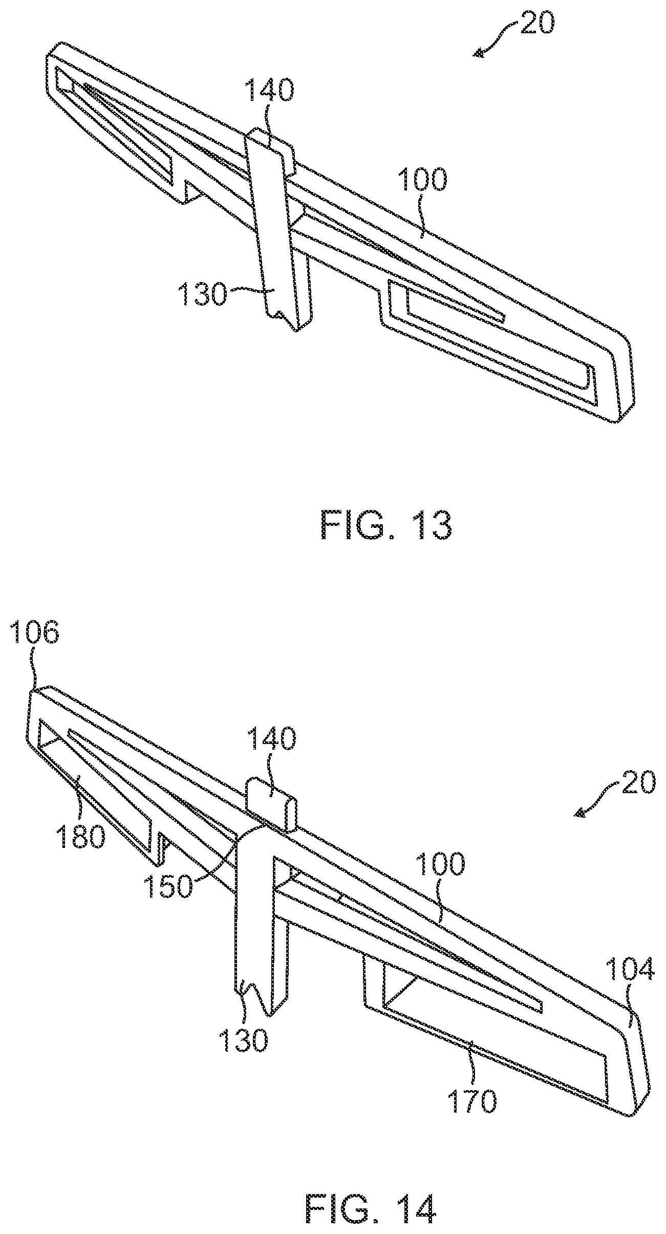
[0021] FIG. 13 is a front perspective view of an alternative embodiment of a picture frame hanger of the present invention;
[0022] FIG. 14 is back perspective view of the alternative embodiment of the picture frame hanger of the present invention;
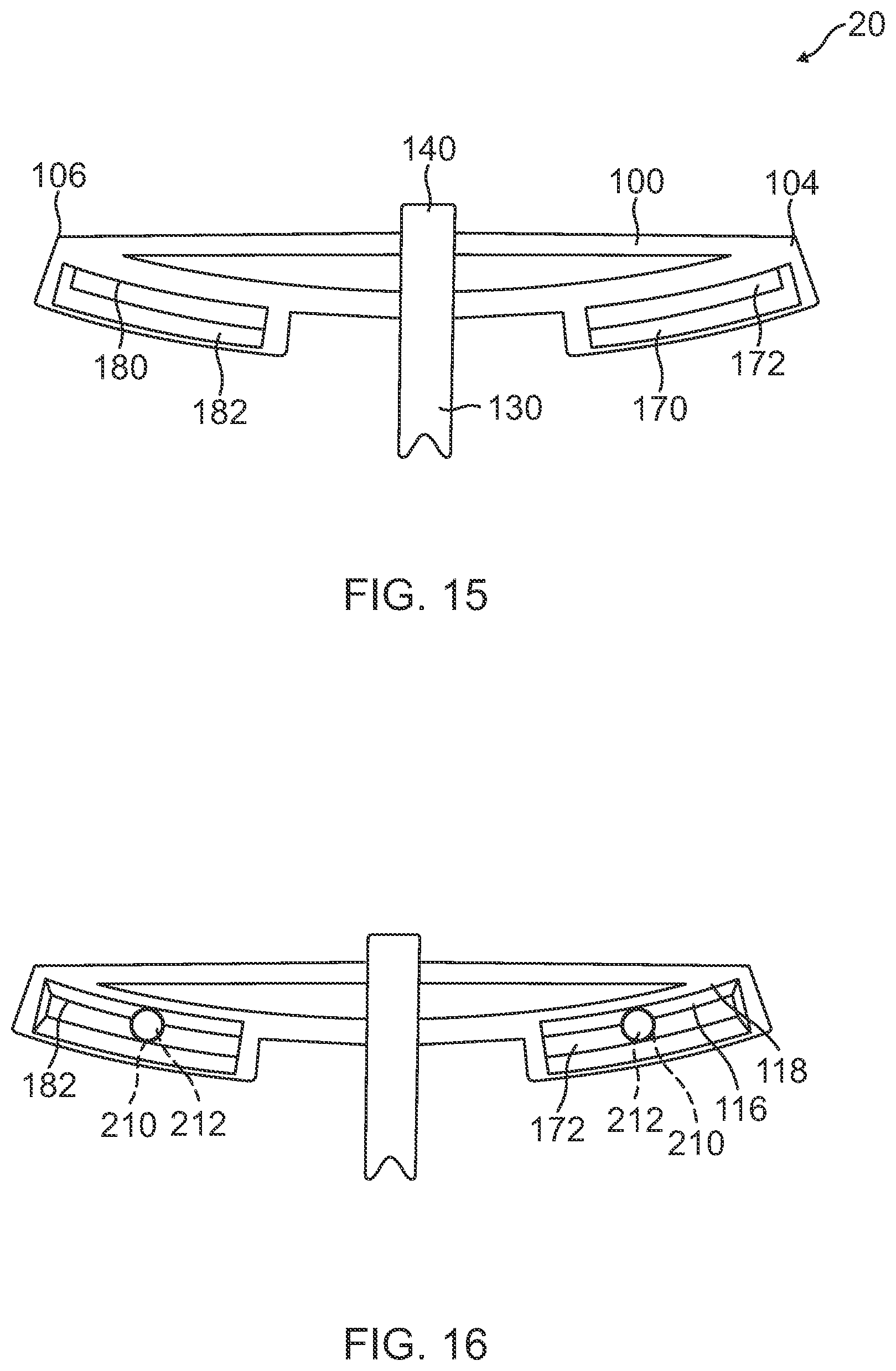
[0023] FIG. 15 is a front view of the alternative embodiment of the picture frame hanger of the present invention;
[0024] FIG. 16 is a front view of the alternative embodiment of the picture frame hanger of the present invention attached to a pair of nails;
[0025] FIG. 17 is a rear perspective view of the picture frame hanger of the present invention attached to a wall with the pair of nails and with a picture having a saw tooth hanger attached to and resting on the alternative embodiment of the picture frame hanger;
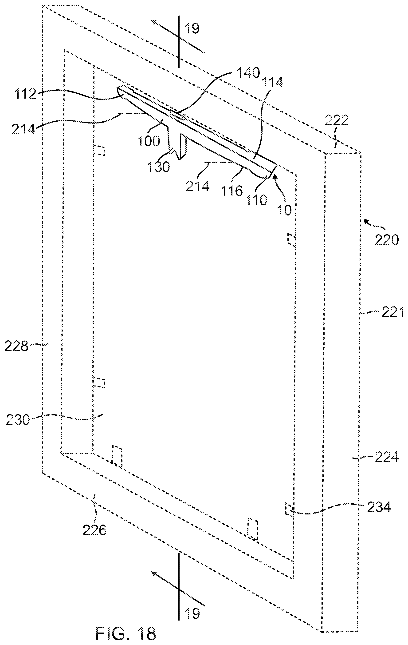
[0026] FIG. 18 is a perspective view of an alternative embodiment of the present invention including a proprietary picture frame to be used with the picture frame hanger; and
[0027] FIG. 19 is a cross-section view of the proprietary picture frame attached to and resting on the picture frame hanger.
DETAILED DESCRIPTION OF THE INVENTION
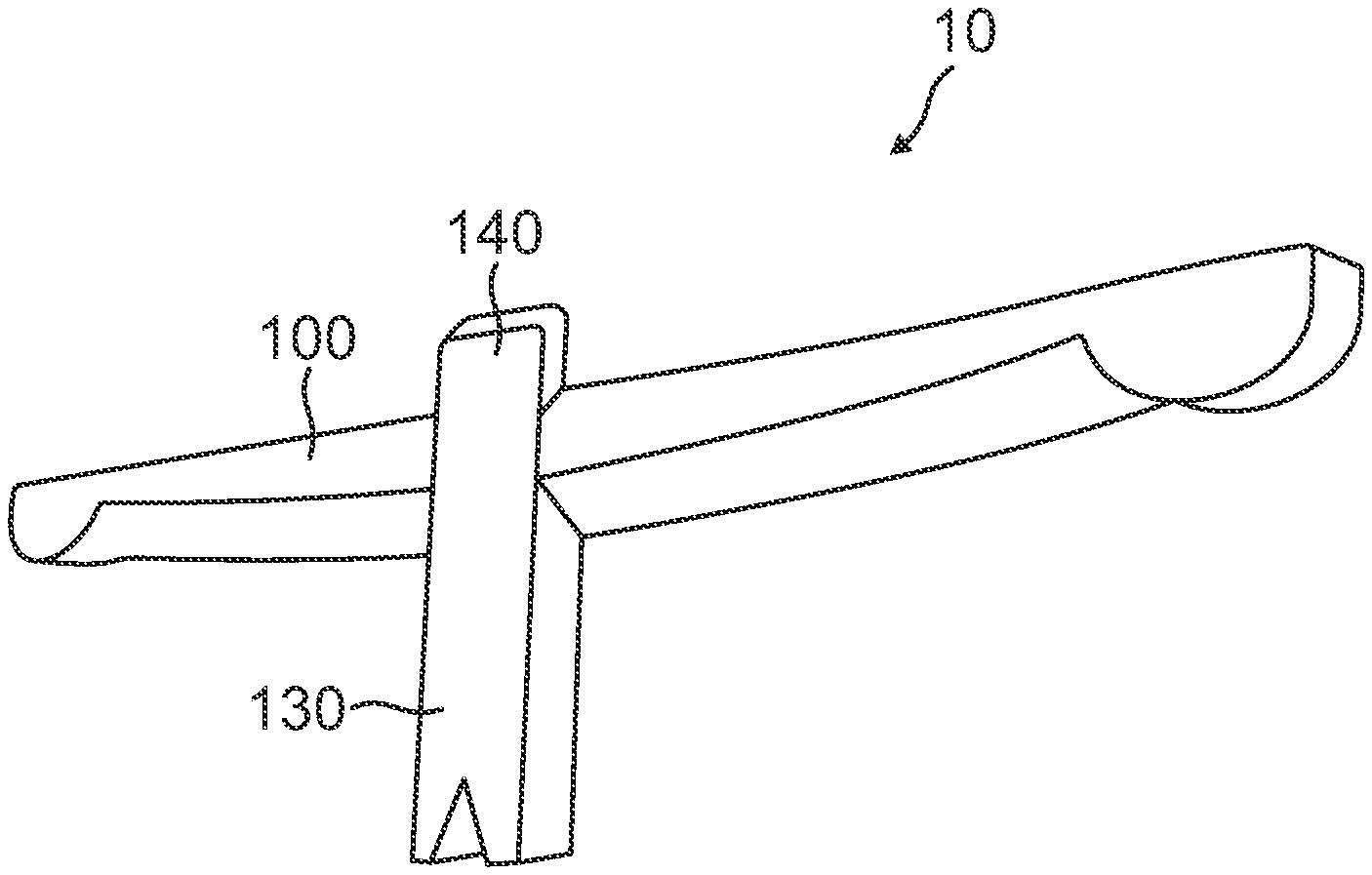
[0028] Referring initially to FIG. 1, a perspective view of the present invention, a picture frame hanger, is shown and generally designated 10. The picture frame hanger 10 includes a horizontal level bar 100, a vertical support bar 130, and a securing tab 140. The vertical support bar 130 is at the mid-point of the horizontal level bar 100 with the securing tab 140 protruding upward from the horizontal level 100 opposite of the vertical support bar 130. The picture frame hanger 10 is an apparatus utilized to simplify the installation of a picture frame on a vertical surface. The picture frame hanger 10 also improves the ability to level and hold the picture frame level once hung on a wall. In addition, the picture frame hanger 10 works in conjunction with the hanging hardware provided with a picture frame, thus reducing the amount of extra components required to hang a picture on the wall.
[0029] Referring now to FIG. 2, a back perspective view of the picture frame hanger 10 is shown. As shown in FIG. 1, the horizontal level bar 100, the vertical support bar 130 and the securing tab 140 are flush on the front of the picture frame hanger 10. On the back of the picture frame hanger 10, the horizontal level bar 100 and the vertical support bar 130 are flush; the securing tab 140 is positioned forward of the back of the picture frame hanger 10 leaving a gap. The flat and even back surface allows the picture frame hanger 10 to lay flat against a vertical surface and the flat and even front surface allows a picture frame to lie flat against the picture frame holder 10. The front and back surfaces of the picture frame holder 10 also ensures that a picture frame holder 10 provides a straight vertical position for attachment of a picture frame. In an embodiment of the picture frame hanger 10, the picture frame hanger 10 is a single piece plastic injection molded component. The method and material of manufacture for the picture frame hanger 10 is not meant to be limiting and it is contemplated that it can be manufactured of more than one part and of materials other than plastic, for example, such as polymers, woods, and metal.
[0030] The horizontal level bar 100, described in conjunction with FIGS. 3-6, has a length 102 between a right edge 104 and a left edge 106 with a thickness 108. A right stop 110 is formed at the right edge 104 with a left stop 112 formed at the left edge 106. A top leveled surface 114 spans the length 102 of the horizontal level bar 100 and a bottom curved surface 116 extends between the right stop 110 to the left stop 112. The curved bottom surface 116 has a degree of curvature 120 and edge thickness 117. The curved bottom surface 116 is further formed with a beveled edge 118 with a beveled edge angle 122. The edge thickness 117 and the beveled edge 118 of the curved bottom surface 116 serves as a hook to catch on nails, screws, or other protruding anchors and the curved bottom surface 116. The degree of curvature 120 of the bottom curved surface 116 allows the picture frame hanger 10 to rotate for the leveling of an attached picture frame. The degree of rotation of the picture frame is dependent on the degree of curvature 120; a larger degree of curvature 120 the less rotation, whereas a smaller degree of curvature 120 the more rotation.
[0031] The vertical support bar 130, described in conjunction with FIGS. 5, 7, and 8, has a height 132 between a bottom edge 134 and a top edge 136 and a length 133. The vertical support bar 130 has a thickness 138 equal to the thickness 108 of the horizontal level bar 100. The vertical support bar 130 has length 132 to provide a lever arm to counteract the downward force and torque created by the hanging of a picture frame onto the picture frame hanger 10. The vertical support bar 130 ensures that the picture frame hanger 10 does not tilt forward and detach from a vertical surface.
[0032] The securing tab 140, described in conjunction with FIGS. 6-8, has a height 142 spanning between a bottom edge 144 and a top edge 146 and a length 143 equal to the length 133 of the vertical support bar 130. The securing tab 140 has a thickness 148 smaller than the thickness 108 and 138. The securing tab 140 is flush with the front of the horizontal level bar 100 and the vertical support bar 130. Due to the thickness 148 of the securing tab 140, a gap 150 is provided between the back of the horizontal level bar 100 and the back of the securing tab 140. As shown only a single securing tab 140 is shown. It is contemplated that the securing tab 140 may have different dimensions and have more than one securing tab 140 to accommodate a variety of standard hanging hardware without departing from the spirit and scope of the invention.
[0033] Referring now to FIG. 9, in a preferred embodiment of the picture frame hanger 10, the picture frame hanger 10 is hooked onto two fasteners 210, with each fastener having a fastener head 212 and a fastener shank 214. The fasteners 210 are attached to a vertical surface (not shown), which then provides an attachment point for a picture frame 200 (shown in FIG. 12) that is easily accessible, easy to attach, and easy to level. With the two fasteners 210 attached to the vertical surface, the horizontal level bar 100 of the picture frame hanger 10 is hooked onto the two nails. Each fastener 210 is located on each side of the horizontal level bar 100 with the vertical support bar 130 positioned between the two fasteners 210. The edge thickness 117 of the bottom curved surface 116 of the horizontal bar 100, as shown in FIG. 4, is thin enough to slip between the vertical surface and the fastener head 212 of the two fasteners 210 with the beveled edge 118 wedging itself between the vertical surface and the fastener head 212 of the two fasteners 210. The edge thickness 117 and the beveled edge 118 allow the use of the picture frame hanger 10 with different sized fasteners 210 provided with a variety of different picture frames 200.
[0034] Referring now to FIGS. 10 and 11, when hooked into place the horizontal level bar 100 and the vertical support bar 130 of the picture frame hanger 10 rests flat against the vertical surface. The edge thickness 117 of the bottom curved surface 116 of the horizontal bar 100 is thin enough to slip between the vertical surface and the fastener head 212 of the two fasteners 210 and contacts the fastener shank 214. The beveled edge 118 wedges itself between the vertical surface and the fastener head 212 of the two fasteners 210. The gap 150 between the securing tab 140 and the vertical surface provides a slot to hang and secure the picture frame 200 with its proprietary hardware. The vertical support bar 130 provides a lever arm to counteract the downward force and torque created by the hanging of the picture frame 200 onto the picture frame hanger 10. The edge thickness 117 and beveled edge 118 of the horizontal level bar 100 in contact with the fasteners 210 and the vertical support bar 130 in contact with the vertical surface ensures that the picture frame hanger 10 does not tilt forward and detach from a vertical surface.
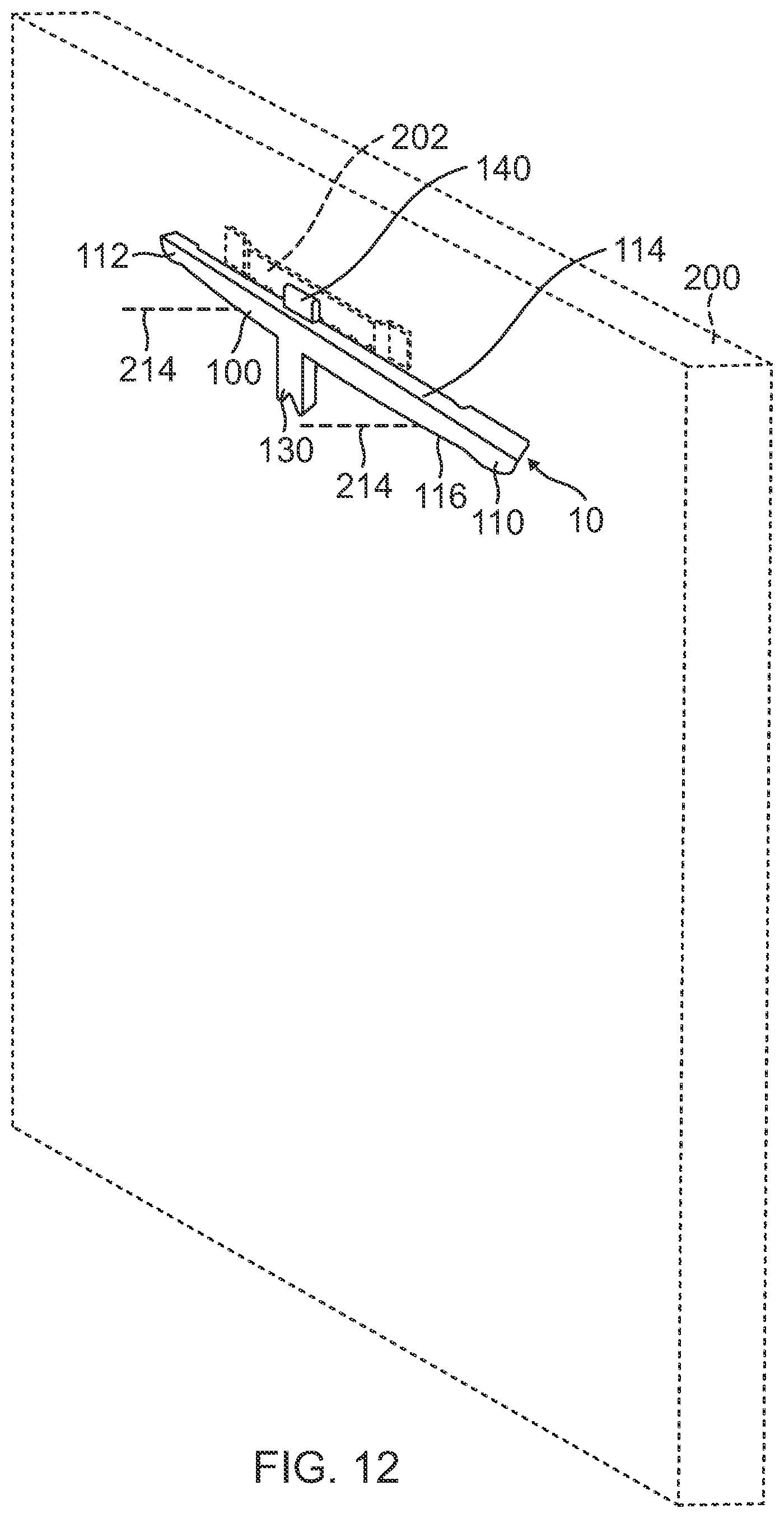
[0035] Referring now to FIG. 12, the picture frame 200 as shown is provided with a saw tooth hanger 202, which is typical of standard picture frames 200. The saw tooth hanger 202 slips over the securing tab 140 and rests on the horizontal level bar 100 and hooks onto the securing tab 140. The horizontal level bar 100 provides a flat leveled surface for the saw tooth hanger 202 to rest upon, which removes a point of error when leveling. Once positioned in place, the picture frame 200 is then able to be leveled by manipulating the picture frame 200. By manipulating the picture frame 200 with the saw tooth hanger 202 lying flat against the horizontal level bar 100, the horizontal level bar 100 will slide against the two fasteners 210. The right stop 110 and left stop 112 provides a maximum rotation of the picture frame hanger 10 and to prevent the picture frame hanger from sliding off of the fasteners 210. Further, the length 143 of the tab 140 is smaller than the saw tooth hanger 202 allowing the saw tooth hanger 202 to move along the length of the horizontal level bar 100 to provide the horizontal adjustment of the picture frame 200 before or after being leveled.
[0036] With the use of two fasteners 210, once the picture frame 200 is leveled the weight of the picture frame 200 creates a downward force resulting in a friction force between the horizontal level bar 100 and the two nails 210 to hold the picture frame 200 level. The weight of the picture frame 200 also creates a torque that is counteracted by the vertical support bar 130 to prevent the picture frame 200 and the picture frame hanger 10 from tilting forward. As shown, the preferred embodiment of the picture frame hanger 10 is an apparatus to be used in conjunction with the supplied picture frame hanging hardware to hang a picture frame. The picture frame hanger 10 allows for the quick and simple installation of the picture frame 200 without the need to pre-measure or pre-level the fasteners, reducing time and effort to hang the picture frame 200. A user can eyeball the leveled position of the two fasteners, hook on the picture frame hanger 10, and adjust the picture frame 200 until level.
[0037] An alternative embodiment of the present invention, a picture frame hanger 20 is shown in FIGS. 13-16. The picture frame hanger 20 is substantially similar to the picture frame hanger 10, wherein like reference numerals designate like features. The picture frame hanger 20 includes a horizontal level bar 100, a vertical support bar 130, and a securing tab 140. The vertical support bar 130 is at the mid-point of the horizontal level bar 100 with the securing tab 140 protruding upward from the horizontal level 100 opposite of the vertical support bar 130. The vertical support bar 130 and the securing tab 140 of the picture frame hanger 20 is substantially similar to the picture frame hanger 10 and includes all of the same features. The horizontal bar 100 of the picture frame hanger 20 is substantially similar to the horizontal bar 100 of the picture frame hanger 10 and includes many of the same features; however, it does not include the right stop and the left stop.
[0038] Instead of having the stops at the ends of the horizontal level bar 100 on the picture frame hanger 20, a right slot frame 170 and a left slot frame 180 protrude downward from the horizontal level bar 100 of the picture frame hanger 20. The right slot frame 170 and the left slot frame 180 protrude downward from the horizontal level bar 100 of the picture frame hanger 20 providing a right slot 172 and a left slot 182. As shown in FIG. 16, the fasteners 210 are inserted through the slots 172 and 182 and attached to the vertical surface. The fastener heads 212 are larger than the slots 172 and 182 and secure the picture frame hanger 20 against the vertical surface. The horizontal level bar 100 includes the curved bottom surface 116 and beveled edge 118 that allows the picture frame hanger 20 to rotate for leveling.
[0039] Referring now to FIG. 17, the picture frame 200 as shown is provided with the saw tooth hanger 202, which is typical of standard picture frames 200. The two fasteners 210 are inserted through the slots 172 and 182 and attached to the vertical surface; the fastener heads 212 secures the picture frame hanger 20 to the vertical surface. The saw tooth hanger 202 of the picture frame 200 slips over the securing tab 140 and rests on the horizontal level bar 100 and hooks onto the securing tab 140. The horizontal level bar 100 provides a flat leveled surface for the saw tooth hanger 202 to rest upon, which removes a point of error when leveling. Once positioned in place, the picture frame 200 is then able to be leveled by manipulating the picture frame 200. By manipulating the picture frame 200 with the saw tooth hanger 200 lying flat against the horizontal level bar 100, the horizontal level bar 100 will slide against the two fasteners 210. The right slot 172 and left slot 182 provides a maximum rotation of the picture frame hanger 10 and to prevent the picture frame hanger from sliding off of the fasteners 210.
[0040] Referring now to FIG. 18, an alternative embodiment of the present invention is shown and includes a proprietary picture frame 220 to be used with the picture frame hanger 10 and any other embodiment of the picture frame hanger 10, including picture frame hanger 20. The picture frame 220, as viewed from the back as shown in FIG. 18, includes a frame 221 having a top member 222, a right member 224, a bottom member 226, and a left member 228. The top member 222, right member 224, bottom member 226, and left member 228 are rigidly connected together to provide the frame 221. The frame 221 provides a lip 234, shown in FIG. 19, to support a transparent panel 240, such as a glass pane. A backing panel 230 is placed behind the transparent panel 240 and a plurality of tabs 140 presses the backing panel 230 against the transparent panel 240 to secure the transparent panel 240 between the lip 234 and the backing panel 230. It is contemplated that different methods of attaching the transparent panel 240 to the frame 221 may be utilized without departing from the spirit and scope of the invention.
[0041] The top member 222 is further formed with a securing tab slot 236. The securing tab slot 236 is formed along the length of the top member 222 and extends the entire length and is configured to accommodate the dimensions of the securing tab 140 of the picture frame hanger 10. It is contemplated that a securing tab slot 236 may also be formed in any or all of the members of the frame 221. For example, to provide a horizontal arrangement of the picture frame 220 the securing tab slot 236 may be formed into the right member 224 or the left 228 member of the frame 221. It is further contemplated that the securing tab slot 236 may be formed directly into a member or as an attachment to a member. Additionally, it is further contemplated that the securing tab slot 236 may be of any shape to accommodate the shape of the securing tab 140. For example, the top of the securing tab 140 may be formed with a lip and the securing tab slot 236 may be formed with an additional channel along the top of the securing tab slot 236 to accommodate the lip of the securing tab 140.
[0042] Referring back to FIG. 18, the securing tab slot 236 slips over the securing tab 140 and the top member 236 rests on the horizontal level bar 100 and hooks onto the securing tab 140. The horizontal level bar 100 provides a flat leveled surface for the top member 236 to rest upon, which removes a point of error when leveling. Once positioned in place, the picture frame 220 is then able to be leveled by manipulating the picture frame 220. By manipulating the picture frame 220 with the top member 236 lying flat against the horizontal level bar 100, the horizontal level bar 100 will slide against the two fasteners 210. The right stop 110 and left stop 112 provides a maximum rotation of the picture frame hanger 10 and to prevent the picture frame hanger from sliding off of the fasteners 210. Further, the length 143 of the tab 140 is smaller than the length of the securing tab slot 236 allowing the top member 236 to move along the length of the horizontal level bar 100 to provide the horizontal adjustment of the picture frame 220 before or after being leveled.
[0043] While the picture frame hanger of the present invention as herein shown and disclosed in detail is fully capable of obtaining the objects and providing the advantages herein before stated, it is to be understood that it is merely illustrative of embodiments of the invention and that no limitations are intended to the details of construction or design herein shown other than as described in the appended claims.
* * * * *
D00000
D00001
D00002
D00003
D00004
D00005
D00006
D00007
D00008
D00009
D00010
XML
uspto.report is an independent third-party trademark research tool that is not affiliated, endorsed, or sponsored by the United States Patent and Trademark Office (USPTO) or any other governmental organization. The information provided by uspto.report is based on publicly available data at the time of writing and is intended for informational purposes only.
While we strive to provide accurate and up-to-date information, we do not guarantee the accuracy, completeness, reliability, or suitability of the information displayed on this site. The use of this site is at your own risk. Any reliance you place on such information is therefore strictly at your own risk.
All official trademark data, including owner information, should be verified by visiting the official USPTO website at www.uspto.gov. This site is not intended to replace professional legal advice and should not be used as a substitute for consulting with a legal professional who is knowledgeable about trademark law.