Motor Unit
NAKAMATSU; Shuhei
U.S. patent application number 17/431425 was filed with the patent office on 2022-04-21 for motor unit. The applicant listed for this patent is NIDEC CORPORATION. Invention is credited to Shuhei NAKAMATSU.
| Application Number | 20220123628 17/431425 |
| Document ID | / |
| Family ID | |
| Filed Date | 2022-04-21 |


| United States Patent Application | 20220123628 |
| Kind Code | A1 |
| NAKAMATSU; Shuhei | April 21, 2022 |
MOTOR UNIT
Abstract
A motor unit including a motor having a rotor rotatable about a motor axis and a stator radially outside the rotor; a housing having a motor housing portion housing the motor; and a refrigerant channel passing through the interior of the housing. A core back portion of the stator has a plurality of fixing portions projecting radially outward from an outer peripheral surface and extending along an axial direction. An upper fixing portion projecting upward from the outer peripheral surface of the core back portion. The refrigerant channel includes a supply portion for feeding refrigerant to the outer peripheral surface of the core back portion. The supply portion is on a side portion of the upper fixing portion in a circumferential direction. The housing includes a breather portion above the upper fixing portion and allows communication between the interior of the motor housing portion and the outside.
| Inventors: | NAKAMATSU; Shuhei; (Kyoto, JP) | ||||||||||
| Applicant: |
|
||||||||||
|---|---|---|---|---|---|---|---|---|---|---|---|
| Appl. No.: | 17/431425 | ||||||||||
| Filed: | January 10, 2020 | ||||||||||
| PCT Filed: | January 10, 2020 | ||||||||||
| PCT NO: | PCT/JP2020/000652 | ||||||||||
| 371 Date: | August 17, 2021 |
| International Class: | H02K 9/19 20060101 H02K009/19; H02K 5/22 20060101 H02K005/22; H02K 7/116 20060101 H02K007/116; H02K 1/32 20060101 H02K001/32; B60L 50/51 20060101 B60L050/51 |
Foreign Application Data
| Date | Code | Application Number |
|---|---|---|
| Mar 6, 2019 | JP | 2019-040863 |
| Apr 11, 2019 | JP | 2019-075237 |
| Jun 13, 2019 | JP | 2019-110648 |
Claims
1. A motor unit comprising: a motor having a rotor that rotates about a motor axis and a stator located radially outside the rotor; a housing having a motor housing portion that houses the motor; and a refrigerant channel that is arranged to pass through an interior of the housing and circulate a refrigerant, wherein a core back portion of the stator has a plurality of fixing portions that are arranged to project radially outward from an outer peripheral surface and extend along an axial direction, and are fixed to the housing, the plurality of fixing portions include an upper fixing portion arranged to project upward from the outer peripheral surface of the core back portion, the refrigerant channel includes a supply portion that feeds the refrigerant to the outer peripheral surface of the core back portion, the supply portion is located on a side portion of the upper fixing portion in a circumferential direction, and the housing is provided with a breather portion that is located above the upper fixing portion and allows an interior of the motor housing portion and an outside of the housing to communicate.
2. The motor unit according to claim 1, wherein the supply portion has a pipe shape extending along the axial direction on the side portion of the upper fixing portion in the circumferential direction, and has a jet hole for jetting the refrigerant on the outer peripheral surface of the core back portion.
3. The motor unit according to claim 2, wherein the jet hole is open toward the outer peripheral surface of the core back portion and a region opposite to the upper fixing portion.
4. The motor unit according to claim 2, wherein an opening of the breather portion in the motor housing portion and the jet hole are arranged at different positions in the axial direction.
5. The motor unit according to claim 1, wherein the refrigerant channel includes the supply portion located on each of both sides of the upper fixing portion in the circumferential direction.
6. The motor unit according to claim 1, wherein a recessed portion for housing the upper fixing portion is provided on an inner peripheral surface of the motor housing portion, and the breather portion is open into the motor housing in the recessed portion.
7. The motor unit according to claim 1, wherein a supply pipe housing recessed portion for housing at least a part of the supply portion is provided on an inner peripheral surface of the motor housing portion.
8. The motor unit according to claim 1, further comprising a gear portion connected to the motor, wherein the housing includes a gear housing portion that houses the gear portion, the refrigerant is oil, and the refrigerant channel is arranged to pass through an interior of the gear housing portion.
Description
CROSS-REFERENCE TO RELATED APPLICATIONS
[0001] This is the U.S. national stage of application No. PCT/JP2020/000652, filed on Jan. 10, 2020 and priority under 35 U.S.C. .sctn. 119(a) and 35 U.S.C. .sctn. 365(b) is claimed from Japanese Patent Application No. 2019-040863, filed on Mar. 6, 2019, Japanese Patent Application No. 2019-075237, filed on Apr. 11, 2019, and Japanese Patent Application No. 2019-110648, filed on Jun. 13, 2019; the disclosures of which are incorporated herein by reference.
FIELD OF THE INVENTION
[0002] The present invention relates to a motor unit.
BACKGROUND
[0003] In a motor unit including a motor and a gear portion, a structure including a breather mechanism for adjusting pressure in a motor housing is known. There is a motor case in which a communicating path leading to a motor chamber is provided in a channel leading from a gear chamber to a breather mechanism. According to such a configuration, it is possible to suppress hydraulic oil from leaking from a breather device.
[0004] In the conventional structure, however, suppression of leakage in a case where a vehicle travels on a slope or the like is not sufficiently considered, and thus, there is a possibility that oil leaks from a breather portion.
SUMMARY
[0005] One aspect of a motor unit of the present invention includes: a motor having a rotor that rotates about a motor axis and a stator located radially outside the rotor; a housing having a motor housing portion that houses the motor; and a refrigerant channel that is arranged to pass through the interior of the housing and circulate a refrigerant. A core back portion of the stator has a plurality of fixing portions that are arranged to project radially outward from an outer peripheral surface and extend along an axial direction, and are fixed to the housing. The plurality of fixing portions include an upper fixing portion arranged to project upward from the outer peripheral surface of the core back portion. The refrigerant channel includes a supply portion that feeds the refrigerant to the outer peripheral surface of the core back portion. The supply portion is located on a side portion of the upper fixing portion in a circumferential direction. The housing is provided with a breather portion that is located above the upper fixing portion and allows the interior of the motor housing portion and the outside of the housing to communicate.
[0006] The above and other elements, features, steps, characteristics and advantages of the present disclosure will become more apparent from the following detailed description of the preferred embodiments with reference to the attached drawings.
BRIEF DESCRIPTION OF THE DRAWINGS
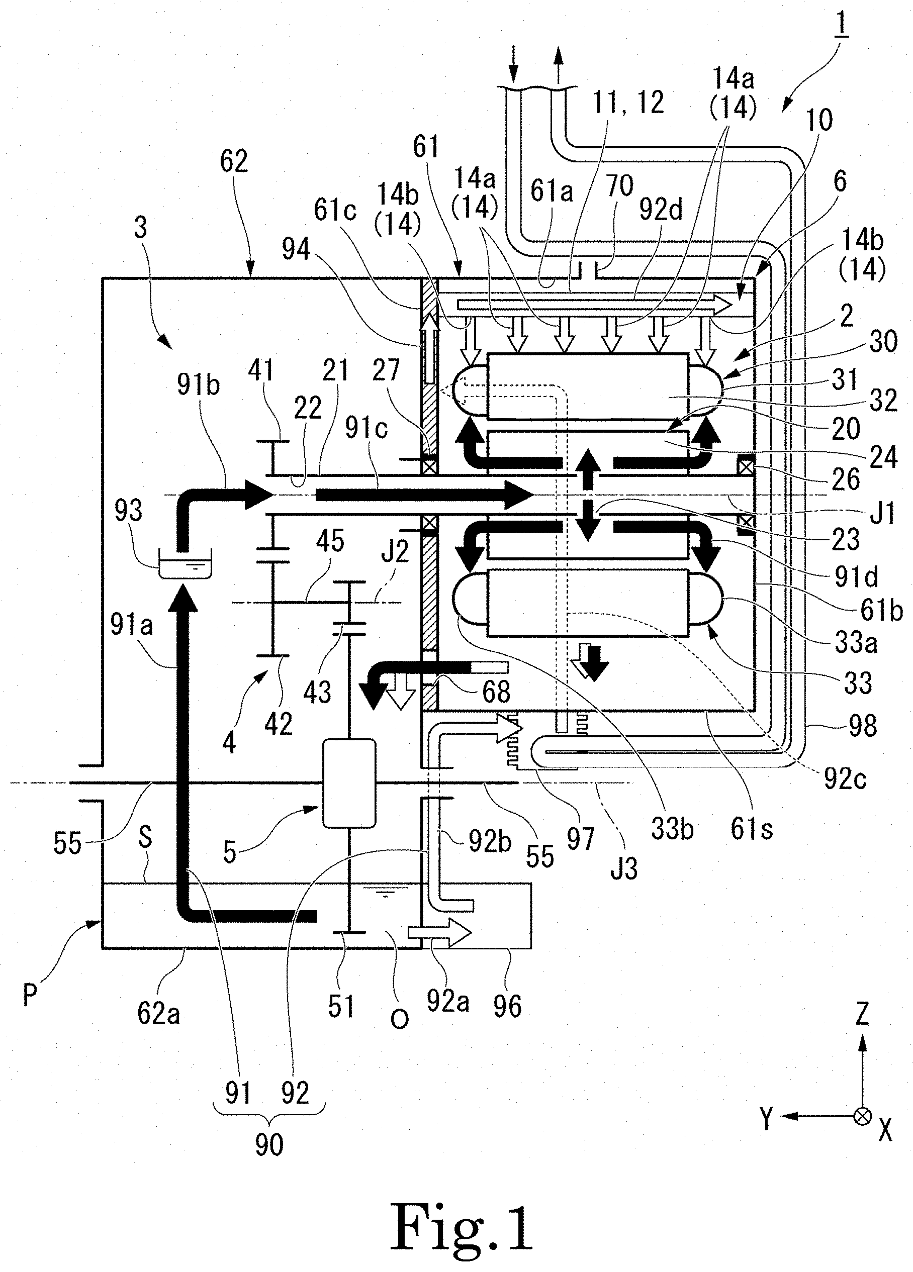
[0007] FIG. 1 is a conceptual configuration diagram schematically illustrating a motor unit according to one embodiment;
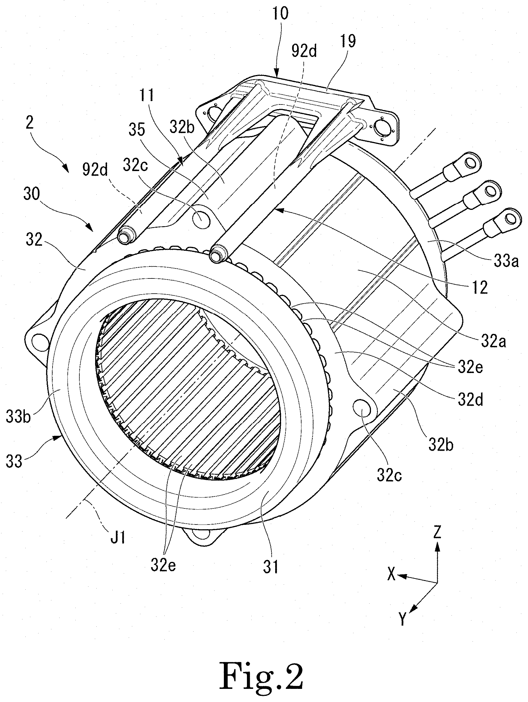
[0008] FIG. 2 is a perspective view illustrating a stator and a supply pipe unit according to one embodiment;
[0009] FIG. 3 is a partial cross-sectional view of a motor unit 1 according to one embodiment; and
[0010] FIG. 4 is a top view illustrating the stator and the supply pipe unit according to one embodiment.
DETAILED DESCRIPTION
[0011] In the following description, a description will be given by defining a vertical direction based on a positional relationship when a motor unit 1 according to an embodiment of the invention is mounted on a vehicle (not illustrated) located on a horizontal road surface. In addition, in the drawings, an xyz coordinate system is shown appropriately as a three-dimensional orthogonal coordinate system. In the xyz coordinate system, a z-axis direction corresponds to the vertical direction. A +z side corresponds to an upper side in the vertical direction, while a -z side corresponds to a lower side in the vertical direction. In the present embodiment, the upper side in the vertical direction and the lower side in the vertical direction will be referred to simply as the "upper side" and the "lower side", respectively. An x-axis direction is a direction orthogonal to the z-axis direction and is a front-rear direction of the vehicle on which the motor unit 1 is mounted. In the present embodiment, a +x side is a front side of the vehicle, and a -x side is a rear side of the vehicle. A y-axis direction corresponds to a left-right direction of the vehicle, i.e., a width direction of the vehicle, and is a direction perpendicular to both the x-axis direction and the z-axis direction. In the present embodiment, a +y side is a left side of the vehicle, and a -y side is a right side of the vehicle. The y-axis direction corresponds to an axial direction of a motor axis J1 to be described later. Each of the front-rear direction and the left-right direction is a horizontal direction perpendicular to the vertical direction. In the present embodiment, the left side corresponds to one side in an axial direction, and the right side corresponds to the other side in the axial direction. In addition, the front side corresponds to one side in the horizontal direction, and the rear side corresponds to the other side in the horizontal direction.
[0012] Note that the positional relationship in the front-rear direction is not limited to the positional relationship in the present embodiment, and the +x side may be the rear side of the vehicle, and the -x side may be the front side of the vehicle. In this case, the +y side corresponds to the right side of the vehicle, while the -y side corresponds to the left side of the vehicle.
[0013] The motor axis J1 illustrated appropriately in the drawings extends in the y-axis direction, i.e., the left-right direction of the vehicle. In the present embodiment, a direction parallel to the motor axis J1 is simply referred to as the "axial direction", a radial direction having its center on the motor axis J1 is simply referred to as the "radial direction", and a circumferential direction having its center on the motor axis J1, that is, the axial circumference of the motor axis J1, is simply referred to as the "circumferential direction" unless otherwise noted. In the present embodiment, one side in the axial direction ((i.e., +y side) is a direction from a motor housing portion 61 to a gear housing portion 62 of a housing 6, which will be described later, in the axial direction. The other side in the axial direction (i.e., -y side) is a direction from the gear housing portion 62 to the motor housing portion 61 in the axial direction. Note that, in the present embodiment, the "parallel direction" also includes a substantially parallel direction, and the "perpendicular direction" also includes a substantially perpendicular direction.
[0014] FIG. 1 is a conceptual diagram schematically illustrating the motor unit 1. The motor unit 1 of the present embodiment is mounted on a vehicle using a motor as a motive power source, such as a hybrid electric vehicle (HEV), a plug-in hybrid vehicle (PHV), and an electric vehicle (EV), and is used as the motive power source.
[0015] The motor unit 1 includes a motor 2, a gear portion 3 including a reduction gear 4 and a differential 5, the housing 6, and an oil passage (refrigerant channel) 90. The oil passage 90 includes a pump 96, a cooler 97, a first supply pipe (supply portion) 11, and a second supply pipe (supply portion) 12. Note that the first supply pipe 11 and the second supply pipe 12 form a part of a supply pipe unit 10.
[0016] The housing 6 includes the motor housing portion 61 that houses the motor 2, the gear housing portion 62 that houses the gear portion 3, a partition 61c that partitions the interior of the motor housing portion 61 and the interior of the gear housing portion 62 in the axial direction, and a breather portion 70. The gear housing portion 62 is arranged to the left side ((i.e., +y side) of the motor housing portion 61. A bottom portion 61s of the motor housing portion 61 is located higher than a bottom portion 62a of the gear housing portion 62. The partition 61c includes a partition opening 68 defined therein. The partition opening 68 is arranged to join the interior of the motor housing portion 61 and the interior of the gear housing portion 62 to each other. The partition 61c is located on the left side of the stator 30.
[0017] Oil O as a refrigerant is housed in the interior of the housing 6. In the present embodiment, the refrigerant is the oil O. In the present preferred embodiment, the oil O (refrigerant) is housed in the interior of the motor housing portion 61 and the interior of the gear housing portion 62. An oil pool P, i.e., a pool of the oil O, is arranged in a lower region in the interior of the gear housing portion 62. The oil O in the oil pool P is sent to the interior of the motor housing portion 61 through the oil passage 90. The oil O sent to the interior of the motor housing portion 61 is gathered in a lower region in the interior of the motor housing portion 61. At least a portion of the oil O gathered in the interior of the motor housing portion 61 travels into the gear housing portion 62 through the partition opening 68 to return to the oil pool P.
[0018] The oil O is arranged to circulate through the oil passage 90, which will be described below. The oil O functions not only for cooling the motor 2 but also for lubricating the gear portion 3. An oil equivalent to a lubricating oil (ATF: Automatic Transmission Fluid) for an automatic transmission having a relatively low viscosity is preferably used as the oil O so that the oil O can perform functions of a lubricating oil and a cooling oil.
[0019] In the present preferred embodiment, the motor 2 is an inner-rotor motor. The motor 2 includes a rotor 20, the stator 30, and a plurality of bearings 26 and 27. The rotor 20 is arranged to be capable of rotating about the motor axis J1, which extends in the horizontal direction. The rotor 20 includes a shaft 21 and a rotor body 24. Although not illustrated in the drawings, the rotor body 24 includes a rotor core, and a rotor magnet fixed to the rotor core. A torque of the rotor 20 is transferred to the gear portion 3.
[0020] The shaft 21 is arranged to extend in the axial direction with the motor axis J1 as a center. The shaft 21 is arranged to rotate about the motor axis J1. The shaft 21 is a hollow shaft including a hollow portion 22 defined therein. The shaft 21 includes a communicating hole 23 defined therein. The communicating hole 23 is arranged to extend in a radial direction to join the hollow portion 22 to a space outside of the shaft 21.
[0021] The shaft 21 is arranged to extend over the interior of the motor housing portion 61 and the interior of the gear housing portion 62 of the housing 6. An end portion of the shaft 21 on the left side is arranged to project into the interior of the gear housing portion 62. A first gear 41, which will be described below, of the gear portion 3 is fixed to the end portion of the shaft 21 on the left side. The shaft 21 is rotatably supported by the bearings 26 and 27.
[0022] The stator 30 is arranged radially opposite to the rotor 20 with a gap therebetween. The stator 30 is located radially outside the rotor 20. An outer peripheral surface of the stator 30 opposes an inner peripheral surface of the housing 6. The stator 30 includes a stator core 32 and a coil assembly 33. The stator core 32 is fixed to an inner surface of the motor housing portion 61.
[0023] FIG. 2 is a perspective view illustrating the stator 30 and the supply pipe unit 10 located above the stator 30.
[0024] The stator core 32 includes a cylindrical core back portion 32d arranged to extend in the axial direction, and a plurality of tooth portions 32e arranged to extend radially inward from the core back portion 32d. The plurality of tooth portions 32e are arranged at intervals in the circumferential direction. The plurality of tooth portions 32e are arranged at regular intervals over the entire circumference in the circumferential direction.
[0025] The core back portion 32d has a plurality of fixing portions 32b projecting radially outward from an outer peripheral surface. The fixing portion 32b is fixed to the inner surface of the motor housing portion 61. That is, the stator 30 is fixed to the housing 6 at the fixing portion 32b. A plurality of the fixing portions 32b are provided at intervals in the circumferential direction. The number of fixing portions 32b is, for example, four. The four fixing portions 32b are arranged at regular intervals over the entire circumference in the circumferential direction.
[0026] The fixing portion 32b is arranged to extend along the axial direction. In the present embodiment, the fixing portion 32b is arranged to extend, for example, from an end portion of the stator core 32 on the left side (i.e., the +y side) to an end portion of the stator core 32 on the right side (i.e., the -y side). That is, the fixing portion 32b is arranged to extend over the entire length of the stator core 32 in the axial direction.
[0027] The fixing portion 32b includes a through hole 32c arranged to pass through the fixing portion 32b in the axial direction. A bolt (not illustrated), which is arranged to extend in the axial direction, is inserted into the through hole 32c. The bolt is arranged to pass through the through hole 32c from the right side (i.e., -y side) and is screwed into a female screw hole (not illustrated) provided on the inner surface of the motor housing portion 61. As a result of the bolt being screwed into the female screw hole, the fixing portion 32b is fixed to the motor housing portion 61.
[0028] In the following description of the present specification, one of the plurality of (four in the present embodiment) fixing portions 32b projecting upward from the outer peripheral surface of the core back portion 32d is referred to as an upper fixing portion 35. That is, one of the plurality of fixing portions 32b includes the upper fixing portion 35. Note that the other fixing portions 32b project downward, forward (i.e., +x side), and backward (i.e., -x side), respectively.
[0029] Referring to FIG. 1, the coil assembly 33 includes a plurality of coils 31 attached to the stator core 32. The plurality of coils 31 are respectively mounted on the tooth portions 32e of the stator core 32 with an insulator (not illustrated) therebetween. The plurality of coils 31 are arranged side by side in the circumferential direction. The plurality of coils 31 are arranged at regular intervals over the entire circumference in the circumferential direction. Although not illustrated in the drawings, the coil assembly 33 may include a binding member or the like which is used to bind the coils 31 together, and may include a passage line arranged to join the coils 31 to one another.
[0030] The coil assembly 33 includes a pair of coil ends 33a and 33b each of which is arranged to project in the axial direction from the stator core 32. The coil end 33a is a portion of the coil assembly 33 that projects to the right side (i.e., -y side) from the stator core 32. The coil end 33b is a portion of the coil assembly 33 that projects to the left side (i.e., +y side) from the stator core 32. The coil end 33a includes a portion of each of the coils 31 included in the coil assembly 33 which projects on the right side of the stator core 32. The coil end 33b includes a portion of each of the coils 31 included in the coil assembly 33 which projects on the left side of the stator core 32.
[0031] Referring to FIG. 2, each of the coil ends 33a and 33b is in the shape of a circular ring, and is centered on the motor axis J1 in the present preferred embodiment. Although not illustrated in the drawings, each of the coil ends 33a and 33b may include a binding member or the like which is used to bind the coils 31 together, and may include a passage line arranged to join the coils 31 to one another.
[0032] Referring to FIG. 1, the bearings 26 and 27 are arranged to rotatably support the rotor 20. Each of the bearings 26 and 27 is, for example, a ball bearing. The bearing 26 is a bearing arranged to rotatably support a portion of the rotor 20 which is located on the right side of the stator core 32. In the present preferred embodiment, the bearing 26 is arranged to support a portion of the shaft 21 which is located on the right side of a portion of the shaft 21 to which the rotor body 24 is fixed. The bearing 26 is held by a wall portion 61b of the motor housing portion 61 which covers the right side of the rotor 20 and the stator 30. The wall portion 61b forms a part of the wall portion of the housing 6 and closes an opening on the right side of the motor housing portion 61.
[0033] The bearing 27 is a bearing arranged to rotatably support a portion of the rotor 20 which is located on the left side of the stator core 32. In the present preferred embodiment, the bearing 27 is arranged to support a portion of the shaft 21 which is located on the left side of the portion of the shaft 21 to which the rotor body 24 is fixed. The bearing 27 is held by the partition 61c.
[0034] The gear portion 3 is housed in the gear housing portion 62 of the housing 6. The gear portion 3 is connected to the motor 2. In more detail, the gear portion 3 is connected to the end portion of the shaft 21 on the left side. The gear portion 3 includes the reduction gear 4 and the differential 5. A torque outputted from the motor 2 is transferred to the differential 5 through the reduction gear 4.
[0035] The reduction gear 4 is connected to the motor 2. The reduction gear 4 is arranged to increase the torque outputted from the motor 2 in accordance with a reduction ratio while reducing the rotation speed of the motor 2. The reduction gear 4 is arranged to transfer the torque outputted from the motor 2 to the differential 5. The reduction gear 4 includes the first gear 41, a second gear 42, a third gear 43, and an intermediate shaft 45.
[0036] The first gear 41 is fixed to an outer circumferential surface of the end portion of the shaft 21 on the left side. The first gear 41 is arranged to rotate about the motor axis J1 together with the shaft 21. The intermediate shaft 45 is arranged to extend along an intermediate axis J2 parallel to the motor axis J1. The intermediate shaft 45 is arranged to rotate about the intermediate axis J2. The second gear 42 and the third gear 43 are fixed to an outer peripheral surface of the intermediate shaft 45 at intervals in the axial direction. The second gear 42 and the third gear 43 are connected to each other through the intermediate shaft 45. Each of the second gear 42 and the third gear 43 is arranged to rotate about the intermediate axis J2. The second gear 42 is arranged to mesh with the first gear 41. The third gear 43 is arranged to mesh with a ring gear 51, which will be described below, of the differential 5.
[0037] The torque outputted from the motor 2 is transferred to the ring gear 51 of the differential 5 through, in order, the shaft 21, the first gear 41, the second gear 42, the intermediate shaft 45, and the third gear 43. The number of gears, the gear ratios of the gears, and the like can be modified appropriately in accordance with a desired reduction ratio. In the present preferred embodiment, the reduction gear 4 is a speed reducer of a parallel-axis gearing type, in which center axes of gears are arranged in parallel with each other.
[0038] The differential 5 is connected to the motor 2 through the reduction gear 4. The differential 5 is a device arranged to transfer the torque outputted from the motor 2 to wheels of the vehicle. The differential 5 is arranged to transfer the same torque to axles 55 of left and right wheels while absorbing a difference in speed between the left and right wheels when the vehicle is turning. In this manner, the gear portion 3 is arranged to transfer the torque of the motor 2 to the axles 55 of the vehicle through the reduction gear 4 and the differential 5 in the present preferred embodiment. The differential 5 includes the ring gear 51, a gear housing (not shown), a pair of pinion gears (not shown), a pinion shaft (not shown), and a pair of side gears (not shown). The ring gear 51 is arranged to rotate about a differential axis J3 parallel to the motor axis J1. The torque outputted from the motor 2 is transferred to the ring gear 51 through the reduction gear 4.
[0039] The oil passage 90 is arranged to pass through the housing 6 and circulate the oil O. The oil passage 90 is a channel of the oil O along which the oil O is fed from the oil pool P to the gear portion 3 and the motor 2 and is led back to the oil pool P. The oil passage 90 is arranged to extend over both the interior of the motor housing portion 61 and the interior of the gear housing portion 62.
[0040] Note that the term "oil passage" as used herein refers to a channel of an oil. The concept of "oil passage" includes not only a "flow passage", in which a steady flow of an oil in one direction is generated, but also a channel in which the oil is allowed to temporarily stay, and a channel along which the oil drips. Examples of the channel in which the oil is allowed to temporarily stay include a reservoir arranged to store the oil.
[0041] The oil passage 90 includes a first oil passage 91 and a second oil passage 92. Each of the first oil passage 91 and the second oil passage 92 is arranged to circulate the oil O in the interior of the housing 6.
[0042] First, a common portion between the first oil passage 91 and the second oil passage 92 will be described. Each of the first oil passage 91 and the second oil passage 92 is a channel along which the oil O is fed from the oil pool P to the motor 2 and back into the oil pool P. In each of the first oil passage 91 and the second oil passage 92, the oil O drips from the motor 2 to be gathered in a lower region of the motor housing portion 61. The oil O gathered in the lower region of the motor housing portion 61 is transferred to a lower region of the gear housing portion 62 (i.e., the oil pool P) through the partition opening 68. That is, the first oil passage 91 and the second oil passage 92 include paths for transferring the oil O from the lower region in the motor housing portion 61 to the lower region in the gear housing portion 62.
[0043] The first oil passage 91 includes a scraping-up channel 91a, a shaft feed channel 91b, an intra-shaft channel 91c, and an intra-rotor channel 91d. In addition, a reservoir 93 is arranged in the channel of the first oil passage 91. The reservoir 93 is arranged in the interior of the gear housing portion 62.
[0044] The scraping-up channel 91a is a channel along which the oil O is scraped up from the oil pool P by rotation of the ring gear 51 of the differential 5 to be received by the reservoir 93. The reservoir 93 is arranged to open upward. The reservoir 93 receives a portion of the oil O which has been scraped up by the ring gear 51. In addition, the reservoir 93 also receives portions of the oil O which have been scraped up by the second gear 42 and the third gear 43 in addition to the ring gear 51 when, for example, a liquid surface S of the oil pool P is at a high level, e.g., immediately after the motor 2 is driven.
[0045] In the scraping-up channel 91a, the oil O scraped up by the ring gear 51 is fed to each gear of the gear portion 3 and spreads over a tooth surface of the gear. According to the present embodiment, the oil passage 90 passes through the interior of the gear housing portion 62. As a result, the oil O can be used not only for cooling the motor 2 but also for lubricating the respective gears and the respective bearings in the gear portion 3.
[0046] The shaft feed channel 91b is a channel arranged to lead the oil O from the reservoir 93 into the hollow portion 22 of the shaft 21. The intra-shaft channel 91c is a channel along which the oil O passes in the hollow portion 22 of the shaft 21. The intra-rotor channel 91d is a channel along which the oil O passes through the communicating hole 23 of the shaft 21 and an interior of the rotor body 24, and is scattered to the stator 30.
[0047] In the intra-shaft channel 91c, a centrifugal force acts on the oil O in the interior of the rotor 20 due to the rotation of the rotor 20. Thus, the oil O is continuously scattered radially outward from the rotor 20. In addition, the scattering of the oil O generates a negative pressure in a channel in the interior of the rotor 20, causing the oil O gathered in the reservoir 93 to be sucked into the interior of the rotor 20, so that the channel in the interior of the rotor 20 is filled with the oil O. A portion of the oil O which has reached the stator 30 absorbs heat from the stator 30.
[0048] In the second oil passage 92, the oil O is lifted from the oil pool P, and is fed to the stator 30. The second oil passage 92 is provided with the pump 96, the cooler 97, and the supply pipe unit 10. The second oil passage 92 includes a first flow passage 92a, a second flow passage 92b, a third flow passage 92c, a fourth flow passage 94, a supply pipe internal flow passage 92d, and jet holes 14.
[0049] Each of the first flow passage 92a, the second flow passage 92b, the third flow passage 92c, and the fourth flow passage 94 is defined in a wall portion of the housing 6. The first flow passage 92a is arranged to connect the oil pool P and the pump 96 to each other. The second flow passage 92b is arranged to connect the pump 96 and the cooler 97 to each other. The third flow passage 92c is arranged to join the cooler 97 and the fourth flow passage 94 to each other. The third flow passage 92c is defined in, for example, a wall portion of the motor housing portion 61 on the forward side (i.e., the +x side).
[0050] The fourth flow passage 94 is provided in a wall portion or the partition 61c of the motor housing portion 61. The fourth flow passage 94 is connected to the first supply pipe 11 and the second supply pipe 12 of the supply pipe unit 10. That is, the fourth flow passage 94 is arranged to join the third flow passage 92c and the supply pipe unit 10. For example, the fourth flow passage 94 is arranged to extend in the horizontal direction from a portion connected to the third flow passage 92c toward the rear side (i.e., -x side).
[0051] The supply pipe unit 10 is arranged between an inner peripheral surface 61a of the motor housing portion 61 and the outer peripheral surface of the stator 30. The supply pipe unit 10 is located above the stator 30. An end portion on the left side (i.e., +y side) of the supply pipe unit 10 is fixed to the wall portion or the partition 61c of the motor housing portion 61. The end portion on the left side of the supply pipe unit 10 is connected to the fourth flow passage 94. An end portion on the right side (i.e., -y side) of the supply pipe unit 10 is fixed to a top wall portion or the wall portion 61b of the motor housing portion 61. That is, the supply pipe unit 10 is fixed to the housing 6.
[0052] The supply pipe internal flow passage 92d is a flow passage of the refrigerant arranged in the interior of the supply pipe unit 10. More specifically, the supply pipe internal flow passage 92d is located in each of the interior of the first supply pipe 11 and the interior of the second supply pipe 12 of the supply pipe unit 10. Therefore, the second oil passage 92 is provided with the pair of supply pipe internal flow passages 92d. The supply pipe internal flow passage 92d is arranged to extend in the axial direction. In addition, the pair of supply pipe internal flow passages 92d is connected to the fourth flow passage 94.
[0053] As illustrated in FIG. 2, the first supply pipe 11 and the second supply pipe 12 have a pipe shape extending in the axial direction. The first supply pipe 11 and the second supply pipe 12 are connected to each other by a connecting portion 19 located at the end portion on the right side (i.e., -y side). That is, the supply pipe unit 10 includes the first supply pipe 11, the second supply pipe 12, and the connecting portion 19 that connects the first supply pipe 11 and the second supply pipe 12. In addition, ribs for reinforcing the supply pipe unit 10 are provided between the first supply pipe 11 and the connecting portion 19 and between the second supply pipe 12 and the connecting portion 19.
[0054] The first supply pipe 11 and the second supply pipe 12 are cylindrical pipes arranged to extend linearly along the axial direction. The first supply pipe 11 and the second supply pipe 12 are arranged at intervals in the front-rear direction. The first supply pipe 11 and the second supply pipe 12 are parallel to each other.
[0055] FIG. 3 is a partial cross-sectional view of the motor unit 1 including the supply pipe unit 10.
[0056] The first supply pipe 11 and the second supply pipe 12 are located radially outside the core back portion 32d. In the present embodiment, a radial position of the first supply pipe 11 and a radial position of the second supply pipe 12 are the same. The first supply pipe 11 and the second supply pipe 12 are arranged above the core back portion 32d. A vertical position of the first supply pipe 11 and a vertical position of the second supply pipe 12 are the same.
[0057] When viewed from the axial direction, the upper fixing portion 35 is arranged between the first supply pipe 11 and the second supply pipe 12. That is, the first supply pipe 11 and the second supply pipe 12 are arranged to extend along the axial direction on both side portions of the upper fixing portion 35 in the circumferential direction. When viewed from the axial direction, an imaginary straight line (not illustrated) passing through a central axis of the first supply pipe 11 and a central axis of the second supply pipe 12 intersects with the upper fixing portion 35. The first supply pipe 11 and the second supply pipe 12 are located on the side portions of the upper fixing portion 35 in the circumferential direction. In addition, the first supply pipe 11 is located on one side of the upper fixing portion 35 in the circumferential direction, and the second supply pipe 12 is located on the other side of the upper fixing portion 35 in the circumferential direction.
[0058] FIG. 4 is a top view illustrating the stator and the supply pipe unit.
[0059] As illustrated in FIG. 4, positions of the first supply pipe 11, the second supply pipe 12, and the upper fixing portion 35 in the front-rear direction overlap each other. The first supply pipe 11 is located on the front side (i.e., +x side) of the upper fixing portion 35, and the second supply pipe 12 is located on the rear side (i.e., -x side) of the upper fixing portion 35.
[0060] The first supply pipe 11 and the second supply pipe 12 have the plurality of jet holes 14 penetrating peripheral walls thereof. As illustrated in FIG. 3, the jet holes 14 are arranged to extend in a pipe radial direction perpendicular to the central axis of the first supply pipe 11 or the second supply pipe 12, and allows the interior and the outside of the pipe to communicate. The jet hole 14 has, for example, a circular hole shape. The jet hole 14 is located between the inner peripheral surface of the housing 6 and the outer peripheral surface of the stator 30. The jet hole 14 jets the oil O flowing through the supply pipe internal flow passage 92d to the motor 2.
[0061] As illustrated in FIG. 4, the plurality of jet holes 14 are arranged at intervals in the axial direction in the first supply pipe 11 and the second supply pipe 12. According to the present embodiment, the stator 30 can be cooled in a wide range in the axial direction by the oil O jetted from the plurality of jet holes 14 arranged in the axial direction.
[0062] The jet holes 14 are classified into a plurality of first jet holes 14a and a plurality of second jet holes 14b. Each of the first supply pipe 11 and the second supply pipe 12 has four first jet holes 14a and two second jet holes 14b.
[0063] In the first supply pipe 11 and the second supply pipe 12, the two second jet holes 14b are arranged at both end portions, and the four first jet holes 14a are arranged side by side at regular intervals in the axial direction between the two second jet holes 14b.
[0064] Axial positions of the first jet hole 14a overlap an axial position of the stator core 32. Similarly, axial positions of the second jet holes 14b overlap axial positions of the coil ends 33a and 33b. One of the two second jet holes 14b located on the right side opposes the coil end 33a on the right side. Similarly, the other of the two second jet holes 14b located on the left side opposes the coil end 33b on the left side.
[0065] As illustrated in FIG. 3, the first jet hole 14a is open toward the opposite side of the upper fixing portion 35 and downward in the first supply pipe 11 and the second supply pipe 12. That is, the first jet hole 14a is open toward an outer peripheral surface of the core back portion 32d and a region opposite to the upper fixing portion 35. For example, regarding the region opposite to the upper fixing portion 35, an imaginary line VL connecting the first supply pipe 11 and the motor axis J1 is assumed, and the first jet hole 14a faces a region opposite to a region where the upper fixing portion 35 is located with the imaginary line VL as a boundary. The first jet hole 14a jets the oil O to the outer peripheral surface of the core back portion 32d. The oil O jetted to the core back portion 32d drips after cooling the core back portion 32d while flowing along the outer peripheral surface of the core back portion 32d, and is gathered in the lower region in the motor housing portion 61. According to the present embodiment, the first jet hole 14a is open toward the opposite side of the upper fixing portion 35 and downward, the first jet hole 14a is open to a region opposite to the breather portion 70, so that it is possible to suppress the oil O from leaking from the breather portion 70.
[0066] Note that the first jet hole 14a may be open toward the motor axis J1 as another embodiment.
[0067] As illustrated in FIG. 4, the second jet hole 14b is open toward the opposite side of the upper fixing portion 35 and downward. The second jet hole 14b provided on the right side (i.e., -y side) between the plurality of second jet holes 14b feeds the oil O to the coil end 33a on the right side. Between the plurality of second jet holes 14b, the second jet hole 14b provided on the left side (i.e., +y side) jets the oil O to the coil end 33b on the left side. The oil O jetted from the second jet hole 14b is fed from the upper side to the coil ends 33a and 33b, cools the coil end 33a, and then, drips to be gathered in the lower region in the motor housing portion 61.
[0068] Note that the first supply pipe 11 and the second supply pipe 12 serving as the supply portion have a pipe shape in the present embodiment, but the present invention is not limited thereto, and for example, the supply portion may have a gutter shape.
[0069] Next, a relative positional relationship between the first supply pipe 11 and the second supply pipe 12 in the housing 6, and the breather portion 70 will be described with reference to FIG. 3.
[0070] The housing 6 is provided with the breather portion 70. The breather portion 70 allows the interior of the motor housing portion 61 and the outside of the housing 6 to communicate and adjusts the internal pressure of the motor housing portion 61. More specifically, the oil O is sealed in the housing 6 of the motor unit 1 in order to lubricate the reduction gear 4, the differential 5, and the respective bearings and cool the motor 2 by an axial oil feeding system or an oil bath lubrication system, and the breather portion 70 adjusts the internal pressure in the housing 6 so that the oil O does not leak from the housing 6 when the internal pressure in the housing 6 increases due to an increase in temperature in the housing 6 during operation.
[0071] The breather portion 70 includes a vent portion 71 that allows the interior and the outside of the motor housing portion 61 to communicate, and a pipe 72 attached to the vent portion 71. In the present embodiment, the vent portion 71 is a circular hole. In addition, the vent portion 71 is arranged to extend linearly along the vertical direction.
[0072] The pipe 72 is inserted into the vent portion 71. Both ends of the pipe 72 are open and connect the interior of the vent portion 71 and the outside of the housing 6. The pipe 72 has an L shape including a first portion 72a and a second portion 72b bent with respect to the first portion 72a. The first portion 72a is a portion inserted into the vent portion 71 from above. The first portion 72a is arranged to extend in the vertical direction around a central axis J4. The second portion 72b is arranged to extend from an end portion on the upper side of the first portion 72a in a direction perpendicular to the vertical direction. The second portion 72b is located outside the housing 6. A hose (not illustrated) may be provided at a distal end portion of the second portion 72b. In addition, a filter may be provided at a distal end of the hose.
[0073] As illustrated in FIG. 4, the motor 2 is surrounded by the inner peripheral surface 61a of the motor housing portion 61 from the radially outside. The inner peripheral surface 61a of the motor housing portion 61 has a substantially circular shape centered on the motor axis J1.
[0074] The inner peripheral surface 61a of the motor housing portion 61 is provided with a plurality of recessed portions 61k in which the fixing portions 32b are housed. The recessed portion 61k is recessed radially outward. In addition, the recessed portion 61k is arranged to extend along the axial direction. As described above, the core back portion 32d is provided with the four fixing portions 32b. Therefore, the inner peripheral surface 61a of the motor housing portion 61 is provided with four recessed portions 61k. A slight gap is provided between an inner surface of the recessed portion 61k and an outer surface of the fixing portion 32b housed in the recessed portion 61k.
[0075] Here, the recessed portion 61k that houses the upper fixing portion 35 among the four recessed portions 61k is referred to as an upper recessed portion 65. The vent portion 71 of the breather portion 70 is open in the upper recessed portion 65. In the present embodiment, a recess is further formed from an inner peripheral surface of the upper recessed portion 65, and the opening of the vent portion 71 is formed on a bottom surface thereof. That is, the breather portion 70 is open into the motor housing portion 61 in the upper recessed portion 65. The breather portion 70 is located above the upper fixing portion 35 housed in the upper recessed portion 65. The opening of the vent portion 71 is located at the top (i.e., the highest portion) of the inner surface of the upper recessed portion 65.
[0076] As illustrated in FIG. 4, the breather portion 70 is arranged so as to overlap the upper fixing portion 35 when viewed in the vertical direction. That is, the breather portion 70 is located immediately above the upper fixing portion 35. In addition, an axial position of the opening of the breather portion 70 in the motor housing portion 61 is substantially an intermediate position of the stator 30, and is arranged to be shifted from the axial positions of the jet holes 14 of the first supply pipe 11 and the second supply pipe 12.
[0077] As illustrated in FIG. 3, the inner peripheral surface 61a of the motor housing portion 61 is provided with a supply pipe housing recessed portion 61p in which the supply portion (the first supply pipe 11 or the second supply pipe 12) is housed. The inner peripheral surface 61a of the present embodiment is provided with two supply pipe housing recessed portions 61p corresponding to the two supply portions (the first supply pipe 11 and the second supply pipe 12). The two supply pipe housing recessed portions 61p are arranged on both sides of the upper recessed portion 65 in the circumferential direction. The first supply pipe 11 is housed in one of the two supply pipe housing recessed portions 61p, and the second supply pipe 12 is housed in the other.
[0078] According to the present embodiment, the oil O in the motor housing portion 61 can suppress leakage of the oil from the breather portion 70 even when the vehicle travels on a slope since the breather portion 70 is located above the stator core 32. As a result, even when the vehicle travels on the slope, the breather portion 70 can appropriately adjust the internal pressure in the motor housing portion 61.
[0079] Further, the breather portion 70 is located above the upper fixing portion 35 in the present embodiment. The upper fixing portion 35 projects upward with respect to the outer peripheral surface of the core back portion 32d. Therefore, according to the present embodiment, the opening of the breather portion 70 can be separated from the channel through which the oil O flows, and the oil O can be prevented from leaking from the breather portion 70.
[0080] In addition, the first supply pipe 11 and the second supply pipe 12 are located on the side portions of the upper fixing portion 35 in the circumferential direction according to the present embodiment. The oil O supplied from the first supply pipe 11 and the second supply pipe 12 to the outer peripheral surface of the core back portion 32d is blocked by the upper fixing portion 35 and hardly reaches the opening of the breather portion 70. As a result, the oil O can be prevented from leaking from the breather portion 70.
[0081] According to the present embodiment, the supply portion that supplies the oil P to the motor 2 is the pipe-shaped supply pipe (the first supply pipe 11 and the second supply pipe 12) having the jet hole 14. Since the supply portion is formed into the pipe shape, the pressure of the oil O in the flow passage can be increased, and the flow velocity of the oil jetted from the jet hole 14 can be increased. As a result, the oil O can be scattered into a wide range from the jet hole 14, and a wide range of the surface of the motor 2 can be cooled in a well-balanced manner.
[0082] According to the present embodiment, the first jet hole 14a is open toward the outer peripheral surface of the core back portion 32d and the region opposite to the upper fixing portion 35. That is, the oil O jetted from the first jet hole 14a is jetted toward the opposite side of the breather portion 70. Therefore, the oil O jetted from the first jet hole 14a hardly enters the opening of the breather portion 70, and the oil O can be prevented from leaking from the breather portion 70.
[0083] According to the present embodiment, the breather portion 70 is open into the motor housing portion 61 in the upper recessed portion 65 in which the upper fixing portion 35 is housed. The oil O does not reach the opening of the breather portion 70 unless the oil O passes through the gap between the inner surface of the upper recessed portion 65 and the outer surface of the upper fixing portion 35. That is, according to the present embodiment, the oil O hardly enters the opening of the breather portion 70, and the leakage of the oil O from the breather portion 70 can be suppressed.
[0084] According to the present embodiment, the opening of the breather portion 70 in the motor housing portion 61 and the first jet hole 14a are arranged at different positions in the axial direction. That is, it suffices that the breather portion 70 is arranged at a position axially different from the jet holes arranged in one of the two supply portions (the first supply pipe 11 and the second supply pipe 12) in the present embodiment. For example, the supply portion is a pipe having a plurality of jet holes, and the breather portion is located within an axial length of the pipe. Further, the breather portion is arranged at a position not overlapping any of the plurality of jet holes in the axial direction. Note that, in a case where the two supply portions are arranged, the breather portion is preferably arranged at a position where the breather portion does not overlap any of the plurality of jet holes located in the two supply portions in the axial direction. Therefore, the oil O jetted from the first jet hole 14a hardly enters the opening of the breather portion 70, and the oil O can be prevented from leaking from the breather portion 70. Note that, even in a case where a jet hole of one of the two supply portions is at a position different from the breather portion in the axial direction and a jet hole of the other supply portion is at the same position as the breather portion in the axial direction, it is possible to obtain a certain effect of suppressing leakage of oil from the breather portion.
[0085] According to the present embodiment, the two supply portions (the first supply pipe 11 and the second supply pipe 12) are located on the both sides of the upper fixing portion 35 in the circumferential direction. Therefore, the oil O is supplied to the both sides in the circumferential direction of the outer peripheral surface of the core back portion 32d with the upper fixing portion 35 as the center, and the entire stator core 32 can be cooled in a balanced manner.
[0086] In addition, each configuration (constituent element) described in the above-described embodiment, modifications, and the writings may be combined within the scope not departing from the spirit of the present invention, and addition, omission, replacement, and other changes of the configuration are possible. In addition, the present invention is not limited by the above-described embodiment and the like, and is limited only by the scope of the claims.
[0087] Features of the above-described preferred embodiments and the modifications thereof may be combined appropriately as long as no conflict arises.
[0088] While preferred embodiments of the present disclosure have been described above, it is to be understood that variations and modifications will be apparent to those skilled in the art without departing from the scope and spirit of the present disclosure. The scope of the present disclosure, therefore, is to be determined solely by the following claims.
* * * * *
D00000
D00001
D00002
D00003
D00004
XML
uspto.report is an independent third-party trademark research tool that is not affiliated, endorsed, or sponsored by the United States Patent and Trademark Office (USPTO) or any other governmental organization. The information provided by uspto.report is based on publicly available data at the time of writing and is intended for informational purposes only.
While we strive to provide accurate and up-to-date information, we do not guarantee the accuracy, completeness, reliability, or suitability of the information displayed on this site. The use of this site is at your own risk. Any reliance you place on such information is therefore strictly at your own risk.
All official trademark data, including owner information, should be verified by visiting the official USPTO website at www.uspto.gov. This site is not intended to replace professional legal advice and should not be used as a substitute for consulting with a legal professional who is knowledgeable about trademark law.