Regenerable Battery Electrode
Takeuchi; Esther Sans ; et al.
U.S. patent application number 17/511522 was filed with the patent office on 2022-04-21 for regenerable battery electrode. The applicant listed for this patent is Brookhaven Science Associates, LLC, The Research Foundation For The State University of New York. Invention is credited to Amy Catherine Marschilok, Altug S. Poyraz, Esther Sans Takeuchi, Kenneth James Takeuchi.
| Application Number | 20220123293 17/511522 |
| Document ID | / |
| Family ID | 1000006062441 |
| Filed Date | 2022-04-21 |


View All Diagrams
| United States Patent Application | 20220123293 |
| Kind Code | A1 |
| Takeuchi; Esther Sans ; et al. | April 21, 2022 |
REGENERABLE BATTERY ELECTRODE
Abstract
A binder-free, self-supporting electrode including an electrochemically active material in the absence of a binder and a current collector is claimed. The electrochemically active material is a self-supporting transition metal oxide. A method of regenerating the electrode to restore capacity of the electrode is also claimed.
| Inventors: | Takeuchi; Esther Sans; (South Setauket, NY) ; Poyraz; Altug S.; (Port Jefferson, NY) ; Takeuchi; Kenneth James; (South Setauket, NY) ; Marschilok; Amy Catherine; (Stony Brook, NY) | ||||||||||
| Applicant: |
|
||||||||||
|---|---|---|---|---|---|---|---|---|---|---|---|
| Family ID: | 1000006062441 | ||||||||||
| Appl. No.: | 17/511522 | ||||||||||
| Filed: | October 26, 2021 |
Related U.S. Patent Documents
| Application Number | Filing Date | Patent Number | ||
|---|---|---|---|---|
| 15772564 | May 1, 2018 | 11201325 | ||
| PCT/US2016/063814 | Nov 28, 2016 | |||
| 17511522 | ||||
| 62261562 | Dec 1, 2015 | |||
| Current U.S. Class: | 1/1 |
| Current CPC Class: | H01M 10/54 20130101; H01M 4/625 20130101; H01M 2220/30 20130101; Y02T 10/70 20130101; C01P 2006/40 20130101; C01G 45/1228 20130101; H01M 4/505 20130101; H01M 4/48 20130101; H01M 4/624 20130101; H01M 4/131 20130101; Y02W 30/84 20150501; H01M 10/052 20130101 |
| International Class: | H01M 4/505 20060101 H01M004/505; H01M 4/131 20060101 H01M004/131; H01M 10/052 20060101 H01M010/052; H01M 10/54 20060101 H01M010/54; H01M 4/48 20060101 H01M004/48; H01M 4/62 20060101 H01M004/62; C01G 45/12 20060101 C01G045/12 |
Goverment Interests
STATEMENT OF GOVERNMENT LICENSE RIGHTS
[0002] This invention was made with Government support under contract number DE-SC0012704, awarded by the U.S. Department of Energy. The United States Government has certain rights in this invention.
Claims
1. A method of regenerating a cycled electrode comprising: removing the cycled electrode from a battery with capacity fade, where the cycled electrode comprises an electrochemically active material in the absence of a binder and a current collector; regenerating the electrode by a thermal treatment under air; and placing the regenerated electrode in the battery to restore capacity.
2. The method of claim 1, wherein the battery has undergone at least 50 cycles prior to electrode regeneration.
3. The method of claim 1, wherein the electrochemically active material is selected from the group consisting of Zn.sub.xO.sub.y, Mn.sub.xO.sub.y, V.sub.xO.sub.y, Fe.sub.xO.sub.y, Sn.sub.xO.sub.y, La.sub.xMn.sub.yO.sub.z, Ni.sub.xCo.sub.yO.sub.z, and Mo.sub.xO.sub.y, wherein x, y, and z are numbers greater than 0.
4. The method of claim 1, wherein electrochemically active material is a self-supporting transition metal oxide comprising nanofibers.
5. The method of claim 1, further comprising no more than about 20% based upon the total weight of the electrode of a conductive additive selected from the group consisting of nanostructured carbon, graphitic carbon, conductive metal nanoparticles, and metal wire mesh.
6. The method of claim 1, wherein the thermal treatment includes heating the electrode to a temperature greater than 200.degree. C. and less than a thermal decomposition temperature of the electrode.
7. A method of regenerating an electrode comprising: providing the electrode from a battery having a delivered capacity below 60 mAh/g, where the electrode has an electrochemically active material in the absence of a binder and a current collector, and where the electrochemically active material is a self-supporting transition metal oxide, and regenerating the electrode by a thermal treatment under air, wherein the regenerated electrode in a battery has a capacity above 100 mAh/g.
8. The method of claim 7 , wherein the electrochemically active material is selected from the group consisting of Zn.sub.xO.sub.y, Mn.sub.xO.sub.y, V.sub.xO.sub.y, Fe.sub.xO.sub.y, Sn.sub.xO.sub.y, La.sub.xMn.sub.yO.sub.z, Ni.sub.xCo.sub.yO.sub.z, and Mo.sub.xO.sub.y, wherein x, y, and z are numbers greater than 0.
9. The method of claim 7, wherein the self-supporting transition metal oxide comprises nanofibers.
10. The electrode of claim 7, further comprising no more than about 20% based upon the total weight of the electrode of a conductive additive selected from the group consisting of nanostructured carbon, graphitic carbon, conductive metal nanoparticles, and metal wire mesh.
11. The method of claim 7, wherein the thermal treatment includes heating the electrode to a temperature greater than 200.degree. C. and less than a thermal decomposition temperature of the electrode.
12. A method of regenerating a self-supporting, binder-free electrode comprising: providing a battery with a self-supporting, binder-free electrode having an electrochemically active material in the absence of a binder and a current collector, wherein the electrochemically active material is a self-supporting transition metal oxide; obtaining the electrode from the battery after capacity fade; regenerating the electrode by a thermal treatment under air; and placing the regenerated electrode in the battery or in a new battery, wherein the battery or the new battery has a capacity above 100 mAh/g.
13. The method of claim 12, wherein the battery has undergone at least 50 cycles prior to electrode regeneration.
14. The method of claim 12, wherein the battery has undergone at least 250 cycles prior to electrode regeneration.
15. The method of claim 12, wherein the electrochemically active material is selected from the group consisting of Zn.sub.xO.sub.y, Mn.sub.xO.sub.y, V.sub.xO.sub.y, Fe.sub.xO.sub.y, Sn.sub.xO.sub.y, La.sub.xMn.sub.yO.sub.z, Ni.sub.xCo.sub.yO.sub.z, and Mo.sub.xO.sub.y, wherein x, y, and z are numbers greater than 0.
16. The method of claim 12, wherein the self-supporting transition metal oxide comprises nanofibers.
17. The electrode of claim 12, further comprising no more than about 20% based upon the total weight of the electrode of a conductive additive selected from the group consisting of nanostructured carbon, graphitic carbon, conductive metal nanoparticles, and metal wire mesh.
18. The method of claim 17, wherein the conductive additive is nanostructured carbon and the nanostructure carbon is multi-walled carbon nanotubes, fullerene, or graphene.
19. The method of claim 12, wherein the thermal treatment includes heating the electrode to a temperature of between 200.degree. C. and 400.degree. C.
20. The method of claim 12, wherein the thermal treatment includes heating the electrode to a temperature greater than 200.degree. C. and less than a thermal decomposition temperature of the electrode.
Description
CROSS-REFERENCE TO RELATED APPLICATION
[0001] This application is a continuation application of U.S. application Ser. No. 15/772,564, filed on May 1, 2018 which claims priority to International Application No. PCT/US2016/063814 filed on Nov. 28, 2016 which claims priority to U.S. Provisional Application No. 62/261,562 filed on Dec. 1, 2015, the contents of each of which are herein incorporated by reference in their entirety.
BACKGROUND OF THE INVENTION
[0003] Portable electric energy storage issues associated with devices such as consumer electronics and electric vehicles, along with stationary electric energy storage concerns associated with renewable energy generation and the grid, continue to stimulate research in electric energy storage, including batteries. Thus, rechargeable lithium ion batteries (LIBs) occupy a prominent consumer presence due to their high cell potential and gravimetric energy density. However, long electrode cycle lifetimes of LIBs remain a challenge. While a number of factors can contribute to limited LIB usable cycle lifetimes, cathode degradation is a significant factor. Thus, a variety of LIB cathode materials have been studied, including oxides of a variety of first row transition metals (i.e. Mn, Fe, V, Co, and Ni). Under extended lithiation/delithiation cycling, issues including structural strain, amorphization, and irreversible phase changes typically occur at the LIB cathode, resulting in an irreversible capacity loss. Thus environmental concerns, such as disposal and recycling issues, and economic concerns remain.
[0004] Currently used or proposed cathode recycling processes are multistep procedures which involve sequences of mechanical, thermal, and chemical leaching steps. During the mechanical recycling processes, the used cathodes are mechanically crushed and sieved multiple times and the components of the cathode are separated magnetically, gravimetrically (by density), and/or by size (sieving). However, separation is not always efficient; therefore further chemical leaching processes are frequently required for total recovery. Acid digestion is the most common chemical leaching process, and uses highly corrosive concentrated acids or bases. In addition, chemical leaching also requires a neutralizing chemical treatment to recover digested metals. A significant advance in this field was described recently (Chen, et al., "Environmentally friendly recycling and effective repairing of cathode powders from spent LiFePO.sub.4 batteries" Green Chem., 2016,18, 2500-2506, DOI: 10.1039/C5GC02650D) whereby cathode powders from spent LiFePO.sub.4 batteries could be recycled for the first time, using a heat-treatment process. However, the recycled electroactive material required significant reprocessing to generate a new cathode structure.
[0005] Accordingly, there is a need for new electrodes which may be regenerated easily and effectively by recreation of only the cathode and provide restored capacity without cell reconstruction.
SUMMARY OF THE INVENTION
[0006] An electrode structure with active material and no binder is disclosed herein which may enable the regeneration of an electrode to regain its activity after cycle testing. After cycling of a battery with accompanying capacity fade, the electrode could be regenerated by a heat treatment process. The regeneration process may be able to restore capacity to the electrode. The capacity increase as a result of regeneration may be retained during cycling. The regenerated cathodes may deliver .about.200% higher capacity than that of a control cell.
[0007] The invention relates to a binder-free, self-supporting electrode including an electrochemically active material in the absence of a binder and a current collector, wherein the electrochemically active material is a self-supporting transition metal oxide. The self-supporting transition metal oxide is selected from the group consisting of Zn.sub.xO.sub.y, Mn.sub.xO.sub.y, V.sub.xO.sub.y, Fe.sub.xO.sub.y, Sn.sub.xO.sub.y, La.sub.xMn.sub.yO.sub.z, Ni.sub.xCo.sub.yO.sub.z, Mo.sub.xO.sub.y, and Mn.sub.wNi.sub.xCo.sub.yO.sub.z, wherein x, y, and z are numbers greater than 0. Preferably, the self-supporting transition metal oxide is cryptomelane type manganese dioxide OMS-2. Furthermore, the self-supporting transition metal oxide preferably includes nanofibers. The electrode includes no more than about 20% based upon the total weight of the electrode of a conductive additive selected from the group consisting of nanostructured carbon, graphitic carbon, conductive metal nanoparticles, and metal wire mesh. Preferably, the conductive additive is nanostructured carbon and the nanostructure carbon is multi-walled carbon nanotubes, fullerene, or graphene. The preferred nanostructured carbon is multi-walled carbon nanotubes. The weight ratio of active material to conductive additive is about 5:0 or higher.
[0008] Another aspect of the invention relates to a method of regenerating a self-supporting, binder-free electrode including providing a battery with a self-supporting, binder-free electrode described above; removing the electrode from a battery with capacity fade; and regenerating the electrode by a thermal treatment under air, and placing the regenerated electrode in the battery or a new battery.
[0009] In a preferred embodiment, the battery has undergone at least 50 cycles prior to electrode regeneration. In another preferred embodiment, the battery has undergone at least 250 cycles prior to electrode regeneration.
[0010] Another aspect of the invention relates to a binder-free, self-supporting electrode consisting essentially of an electrochemically active material in the absence of a binder and a current collector, wherein the electrochemically active material is a self-supporting transition metal oxide.
DESCRIPTION OF THE DRAWINGS
[0011] FIG. 1A shows a comparison of the powder X-ray diffraction (PXRD) patterns of BFSSC with 0 and 20% w.t CNT and pwdr-OMS-2.
[0012] FIG. 1B shows 20% CNT containing BFSSC-20.
[0013] FIG. 1C shows four-probe resistivity measurements of BFSSCs with varying CNT content (0%, 5%, 10%, 15%, and 20%).
[0014] FIG. 2 Thermal Gravimetric Analysis (TGA) profiles of powder OMS-2 (Pwdr OMS-2), 0&20% CNT containing binder free self-supporting cathode materials, BFSSC-0 and BFSSC-20, respectively. The weight % of CNT in BFSSC-20 was calculated as 18%.
[0015] FIGS. 3A, 3B, and 3C and Table 1 show Mn 2p, Mn 3s, and O1s spectral ranges and peak positions. Binding energies (BEs) of Mn2p.sub.1/2 and Mn2p.sub.3/2 doublets are in the ranges of 654.1-654.3 and 642.7-642.9, respectively (FIG. 3A and Table 1).
[0016] X-ray Photoelectron spectra (XPS) of powder (Pwdr-OMS-2), 20% (BFSSC-20) and 0% (BFSSC-0) CNT containing binder free self-supporting cathode materials. FIG. 3A) Mn 2p, FIG. 3B) Mn 3s,
[0017] FIG. 3C shows the O1s spectral region of OMS-2 materials. O1s peaks were deconvoluted into three different oxygen species (Mn--O--Mn, Mn--OH, and H--O--H (physisorbed water)) and the peak areas of these different oxygen species are presented in Table 1.
[0018] FIGS. 4A-4F SEM images shows as made wirelike OMS-2 materials are consist of nano-fiber bundles, FIGS. 4A and 4B. Upon dispersion and sonication in NMP, the bundles were opened and restacked as individual fibers as seen in the SEM images of the BFSSC surfaces (FIG. 4E). NMP (1-Methyl-2-pyrrolidone) was chosen as dispersing solvent in our studies since it can disperse both CNT and OMS-2 fibers effectively to form homogeneous and stable suspensions (41). The cross sectional SEM image of BFSSC-20 shows that the surface has a flat and smooth surface morphology along with a consistent thickness of 180 .mu.m (FIG. 4D).
[0019] FIG. 4C Schematic diagram of broken BFSSC-20 paper material to observe side and face views, FIG. 4D is the view from side (thickness .about.180 nm), FIGS. 4E and 4F are the images of the surface of BFSSC material with 5 k and 15 k magnifications, respectively.
[0020] FIG. 5A shows the cycling performance of pwdr-OMS-2, BFSSC-0, and BFSSC-20 over 100 cycles. In the figure, the capacity of pwdr-OMS-2 was calculated both per gram of cathode (solid triangle) and per gram of active material (open triangle) and capacities of BFSSCs were calculated per gram of cathode. FIGS. 5B and 5C show the representative charge and discharge curves at 1.sup.st, 10, 50.sup.th, and 100.sup.th cycles of BFSSC-20 and pwder-OMS-2, respectively.
[0021] FIG. 5A) Evolution of discharge capacity over 100 cycles for BFSSC-20 (solid square), BFSSC-0 (solid circle), and powder OMS-2 coating (solid triangle). The capacities were calculated based on the total cathode weight. Open triangle shows the discharge capacity of powder OMS-2 coating where the capacity was calculated per gram of active material. The cells were discharged-charged at a rate of 0.09 mA/cm2. Representative discharge profiles at cycles 1, 10, 50, and 100 were shown at FIG. 5B) for BFSSC-20 and FIG. 5C) for Powder OMS-2 coating.
[0022] FIGS. 6A-6D. shows galvanostatic intermittent titration technique (GITT) conducted on cells with BFSSC cathodes. Galvanostatic Intermittent Titration Technique (GITT) plots of FIG. 6A) BFSSC-20 (20% CNT) and FIG. 6B) Powder OMS-2. 40 mA/g pulses for 10 min and 20 h rest in between the pulses. Diffusion coefficient plots of FIG. 6C) BFSSC-20 (20% CNT) and FIG. 6D) Powder OMS-2.
[0023] FIGS. 7A-7C Electrochemical impedance spectroscopy (EIS) measurements of coin cells with FIG. 7A) BFSSC-20 (20% CNT) and BFSSC-0 (0% CNT). The inset is the low-resistance part of BFSSC-20. FIG. 7B) The impedence measurements of powder OMS-2 coatings with varying coating thicknesses. FIG. 7C) The equivalent electrical circuit used to fit the impedance spectra.
[0024] FIG. 8. Capacity versus cycle number for lithium anode/BFSSC cells under galvanostatic control. The first 50 cycles were for a group of cells using as prepared electrodes. After 50 cycles, three of the cells were selected for regeneration (noted as pink, blue and red). Cycles 50 to 100 for the control cell (black) were continued as for cycles 1-50. The regenerated electrodes were reinserted into cells and the testing was continued.
[0025] FIGS. 9A-9D Morphology of OMS-2. SEM images of a OMS-2 material with different magnifications: FIG. 9A) 2kx, scale bar 10 .mu.m. FIG. 9B) 5kx, scale bar 5 .mu.m. FIG. 9C) 10kx, scale bar 1 .mu.m. FIG. 9D) 20kx, scale bar 1 .mu.m.
[0026] FIGS. 10A and 10B Electrochemical Performance of BFSSCs. FIG. 10A) Galvanostatic cycling performances and FIG. 10B) Coulombic efficiencies of the binder free self-supporting cathode (BFSSC) cycled for 250 cycles (Control cell) and Regenerated BFSSC. BFSSC was regenerated four (4) times after 50 cycles by rinsing with 5 DMC first and then heating under air for 2 h at 300.degree. C. Current density was 50 mA/g (2.0 and 3.9 V vs. Li/Li+).
[0027] FIG. 11 Representative charge/discharge profiles of BFSSC. Initial Galvanostatic Charge/discharge profiles of regenerated BFSSC after the regeneration steps. Cycle numbers are 1, 51, 101, 151, and 201. Current density was 50 mA/g (2.0 and 3.9 V vs. Li/Li+).
[0028] FIGS. 12A-12D Effect of Battery cycling and Regeneration on the BFSSC. FIG. 12A) X-ray Diffraction (XRD) patterns of as-made BFSSC and BFSSCs galvanostatically cycled for 100 and 300 times with 50 mA/g rate. FIG. 12B) Scherrer crystallite sizes of (200) and (310) planes of as-made, 100 times and 300 times cycled BFSSCs, and regenerated BFSSC after 100 cycles. FIG. 12C) XRD patterns of as-made and regenerated BFSSCs. FIG. 12D) Image of BFSSC.
[0029] FIG. 13 Visual and physicochemical properties of BFSSC. Image of a BFSSC material along with the average weight, thickness, and BET surface area. In BFSSC, OMS-2/CNT weight ratio is 5/1, corresponding to 83 wt. % of OMS-2.
[0030] FIGS. 14A-14D High-resolution STEM images showing crystallinity and amorphization of the pristine, 100 cycled, 300 cycled and regenerated BFSSC. FIG. 14A) The pristine sample viewed along the [012] direction, revealing high crystallinity throughout the entire nanorod with a clean crystalline surface. The inset is a magnified area form the boxed region from the edge embedded with the structural model. FIG. 14B) The 100-cycled sample viewed along the [015] zone axis. Although overall the nanorod remains crystalline, the fuzzy contrast and spackle intensity suggest significant amorphization on the sample. The amorphous patches appear at the edge of the image (see the inset) indicate they cover the entire surface of the nanorod. Lattice distortion related defects were also observed. FIG. 14C) The 300-cycled sample. Very thick amorphous layer on surface make the atomic structure in the interior of the nanorod barely visible. FIG. 14D) The regenerated sample after 150 cycles viewed along the [1-21] direction. The amorphous patches on the surface (see the enlarge image in inset from the same boxed area at the edge) has clearly transformed into a single crystal, being consistent with the x-ray and electrochemistry data.
[0031] FIG. 15 Diffraction pattern comparison. X-ray Diffraction (XRD) patterns of as-made grounded OMS-2 and binder free self-supporting cathode BFSSC (83wt. % OMS-2) materials. (K.sub.xMn.sub.8O.sub.16, JCPDS 029-1020).
[0032] FIG. 16: Thermal stability and water content of OMS-2. Thermal Gravimetric Analysis (TGA) profile of OMS-2 (.alpha.-MnO.sub.2). The TGA graph is split into three parts, separated by dashed lines, physisorbed water (RT-250.degree. C.), Structural (Tunnel) Water (250-.about.450.degree. C.), and O.sub.2 evolution (thermal decomposition) (>450.degree. C.).
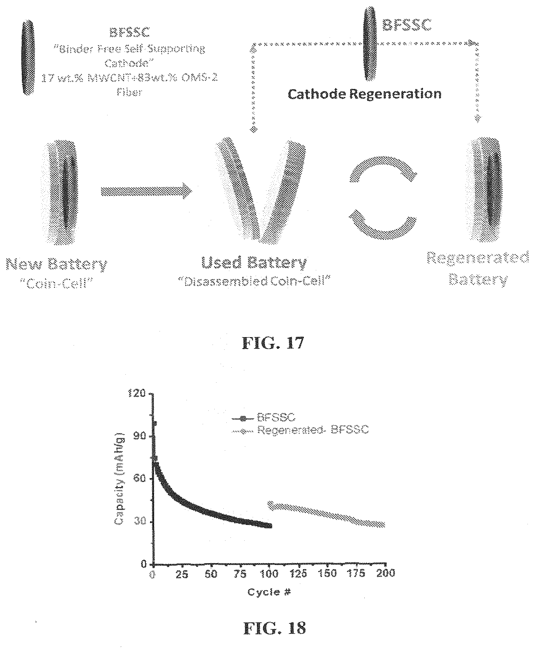
[0033] FIG. 17 Schematic representation of cathode regeneration process: A coin-cell assembled with as-made BFSSC. Used battery was disassembled and BFFSC was removed. BFSSC was regenerated by rinsing with DMC first and then heating under air for 2 h at 300.degree. C. A new battery was assembled with the regenerated BFSSC.
[0034] FIG. 18 Regeneration Control experiment. Galvanostatic cycling performance of BFSSC regenerated by only rinsing with DMC and dried at RT in a vacuum oven (No heating). Current density was 50 mA/g (2.0 and 3.9 V vs. Li/Li.sup.+).
[0035] FIGS. 19A-19D Low-magnification STEM images showing size difference of the pristine, 100 cycled, 300 cycled and regenerated BFSSC. FIG. 19A) The pristine sample; FIG. 19B) The 100 cycled sample; FIG. 19C) the 300 cycled sample; and FIG. 19D) the regenerated sample. Insets are enlarged image of the corresponding nanorods.
DETAILED DESCRIPTION
[0036] The present invention relates to a binder-free, self-supporting electrode including an electrochemically active material. The electrochemically active material is a self-supporting transition metal oxide. The transition metal oxide is self-supporting because of its fibrous morphology. For example, these transition metal oxides can be formulated as long, nanofibers. The long, nanofibers need no further means of support unlike conventional electrodes which are commonly deposited on carbon. In other words, the transition metal oxides of the invention differ from conventional electrodes because they do not need to be anchored, deposited, or placed on a support.
[0037] Examples of transition metals with fibrous morphologies include, but are not limited to, Zn.sub.xO.sub.y, Mn.sub.xO.sub.y, V.sub.xO.sub.y, Fe.sub.xO.sub.y, Sn.sub.xO.sub.y, La.sub.xMn.sub.yO.sub.z, Ni.sub.xCo.sub.yO.sub.z, Mo.sub.xO.sub.y, and Mn.sub.wNi.sub.xCo.sub.yO.sub.z, wherein x, y, and z are numbers greater than 0. For example, preferred transition metal oxides include ZnO, MnO.sub.2, V.sub.2O.sub.5, Fe.sub.2O.sub.3, SnO.sub.2, VO.sub.2, LaMnO.sub.3, and NiCo.sub.2O.sub.4. Most preferably, the electrochemically active material is cryptomelane type manganese oxide (OMS-2, a group of octahedral molecular sieves, K.sub.x1Mn.sub.8O.sub.16, wherein 0.6.gtoreq.x1.gtoreq.1.2).
[0038] Binders and current collectors are also not necessary for the functioning of the electrode. Binders and current collectors for electrodes are well-known in the art. Examples of binders not necessary for the invention include, but are not limited to, polymer binders, water-based binders, and conductive binders. Examples of binders include polyvinylidene difluoride (PVDF), styrene butadiene rubber (SBR), polytetrafluoroethylene (PTFE), sodium-carboxyl-methyl-cellulose (CMC), poly (acrylaminde-co-diallyldimethylammonium) (AMAC), poly (acrylic acid) (PAA), polyaniline (PANI), polypyrrole (PPY), conducting polymer hydrogels (CPHs), Nafion, lignin, and combinations thereof. Examples of current collectors not necessary for the invention include, but are not limited to, Al and Cu foils.
[0039] The invention may optionally include conductive additives that are present for the purpose of increased conductivity, and not for structural purposes to support the electrode. In other words, the electrode is self-supporting without the required presence of a conductive additive. Additionally, the presence of a conductive additive in the electrode is minimal enough such that the conductive additive will not function as a support for the electrode. Accordingly, the quantity of conductive additives is limited to no more than about 20% based upon the total weight of the electrode in order to distinguish the additives from structural supports.
[0040] Additives to increase conductivity in an electrode are well known in the art. Some conductive additives include, but are not limited to, any graphitic carbon, nanostructured carbon, metal wire mesh, and metal nanoparticles such as Ag, Zn, Ni, and Cu. Examples of graphitic carbon include carbon black, graphite, Super P, and Kagen Black.
[0041] Nanostructured carbon includes, but is not limited to, fullerenic carbon (e.g., fullerenes and carbon nanotubes), graphenes, and polyacetylenes. Carbon nanotubes include, e.g., single-walled carbon nanotubes (SWNTs), few-walled carbon nanotubes (FWNTs), and multi-walled carbon nanotubes (MWNTs).
[0042] The term "nanostructured carbon" may exclude functionalized carbon materials, i.e., nanostructured carbon containing various functional groups incorporated in or attached to the carbon framework. The functional groups may include or exclude, for example, oxygen functional groups such as --OH and --COOH. Thus, the term "nanostructured carbon" excludes oxygen-functionalized nanostructured carbon. Types of excluded oxygen-functionalized nanostructured carbon includes materials such as, for example, oxidized FWNTs, oxidized MWNTs (including MWNT-COOH), graphene oxide (GO), reduced graphene oxide (rGO), and rGO--COOH.
[0043] Additionally, the carbon nanotubes may or may not include composites, i.e., when another element or compound is nucleated on the carbon nanotubes. For example, sulfur is not nucleated upon the carbon nanotubes, and the carbon nanotubes are not sulfur-carbon nanotube composites. Furthermore, the carbon nanostructures are not synthesized on carbon felt.
[0044] The term "nanostructured" refers to articles having at least one cross-sectional dimension on the nanometer scale, e.g., less than about I .mu.m, less than about 500 nm, less than about 250 nm, less than about 100 nm, less than about 75 nm, less than about 50 nm, less than about 25 nm, less than about 10 nm, or, in some cases, less than about I nm. Nanostructured carbon includes materials that have features on the nanometer scale in at least one, at least two, or in all three dimensions.
[0045] The conductive additive may not be present in the invention. However, the conductive element may be present in the invention in quantities whereby it is not a structural element of the electrode, and it is present in the invention solely to increase conductivity of the electrode and electrochemical performance of the electrode in general by decreasing the charge polarization.
[0046] For example, the conductive additive may be present in the invention in minimum amount of about 0%, 0.1%, 0.5%, I %, 2%, 3%, 4%, 5%, 6%, 7%, 8%, 9%, 10%, 11%, 12%, 13%, 14%, 15%, 16%, 17%, 18%, or 19% based upon the total weight of the electrode.
[0047] Likewise, the conductive additive may be present in the invention in a maximum amount of about 20%, 19%, 18%, 17%, 16%, 15%, 14%, 13%, 12%, 11%, 10%, 9%, 8%, 7%, 6%, 5%, 4%, 3%, 2%, or I % based upon the total weight of the electrode. Each of the above-listed minima and maxima may be combined to create a range. For example, the conductive additive may be a carbon nanotube present in a minimum amount of about 9% and a maximum amount of about 20%.
[0048] In a preferred aspect of the invention, the transition metal oxide is OMS-2 and a conductive additive such as multi-walled carbon nanotube is present in a preferred ratio of about 5:0 or higher, OMS-2 to multi-walled carbon nanotube.
[0049] In another preferred aspect of the invention, no conductive additive is present.
[0050] Another embodiment of the invention relates to a binder-free, self-supporting electrode consisting essentially of an electrochemically active material in the absence of a binder and a current collector, wherein the electrochemically active material is a self-supporting transition metal oxide. The term "consisting essentially of" would exclude the presence any additive included in the electrode in quantities such that the additive would function as a structural element. The electrode is self-supporting exclusively because of the fibrous morphology of the translation metal oxide. Conductive additives such as any carbon form may be present in this embodiment of the invention, but they are not present in quantities to be considered structural elements. In other words, "consisting essentially of" would include the presence of up to about 20% by total weight of the electrode of a conductive additive according to the invention.
[0051] In another embodiment, the invention relates to a binder-free, self-supporting electrode consisting of cryptomelane type manganese dioxide OMS-2 nanofibers and a nanostructured carbon. The nanostructured carbon may be present in a maximum amount of about 20% of the total composition and a minimum amount of 0% of the total composition.
[0052] The invention also relates to a method of recycling the electrodes described above. The electrode of the invention may be regenerated by thermal treatment so it can be placed in a new battery and re-used. Regenerated electrodes display restored crystallinity and oxidation state of the transition metal centers with resulting electrochemistry (capacity and coulombic efficiency) similar to that of freshly prepared electrodes.
[0053] After a battery containing the electrode of the invention had undergone a significant number of cycles and the capacity had faded, the electrode may be regenerated by removing it from the old battery and rinsing, if necessary, to remove, for example, lithium salt from the electrode surface. Any organic solvent can be used to rinse the battery that can dissolve lithium salt, e.g., DMC (dimethyl carbonate), DEC (diethyl carbonate), EMC (ethyl methyl carbonate), EA (ethyl acetate), MB (methyl butyrate), EB (ethyl butyrate), DMM (dimethoxymethane), DME (dimethoxyethane), and THF (tetrahydrofuran), etc. The electrode is then placed in an oven heated to a temperature high enough so that the transition metal oxide is fully oxidized and low enough so that the electrode is not subject to thermal decomposition. The temperature and duration of the regeneration with respect to a given electrode can be determined by a person having ordinary skill. For example, for an OMS-2/MWNT electrode, regeneration may take place in a 300.degree. C. oven for approximately 2 hours.
[0054] After the electrode is thermally regenerated, the regenerated electrode may be placed in the same battery or in a new battery. The number of discharge-charge cycles before regeneration may be determined by monitoring the performance of the battery to determine capacity fade. The number of cycles may be anywhere between from about 50 to a number of cycles even greater than about 250.
[0055] The invention may be practiced in the absence of any element which is not specifically disclosed herein.
[0056] Examples have been set forth below for the purpose of illustration and to describe the best mode of the invention at the present time. The scope of the invention is not to be in any way limited by the examples set forth herein.
EXAMPLES
Example 1. Materials Characterization
[0057] Potassium containing cryptomelane type OMS (OMS-2) fibers were synthesized by the redox reaction between Mn.sup.2+ and S.sub.2O.sub.8.sup.2- under hydrothermal conditions. Binder-free self-supporting cathode (BFSSC) materials were prepared by dispersing the fibers with varying amounts of multiwall carbon nanotube (CNT) in NMP and filtering through a glass membrane. For comparison, as made OMS-2 fibers were grounded to fine powder and labeled as Pwdr-OMS-2. FIG. 1A shows the X-ray diffraction (XRD) patterns of BFSSC with 0 and 20% w.t CNT and pwdr-OMS-2. Diffractions lines of both BFSSC and pwdr-OMS-2 are in agreement with the tetragonal cryptomelane phase (JCPDS file number 29-1020) with substantially no detected impurities. One difference between BFSSCs and pwdr-OMS-2 (and the standard pattern) may be the higher relative intensities of (hk0) diffraction lines compared to (001) lines. The (hk0) crystallographic planes may be parallel to the 2.times.2 tunnels. Therefore, higher intensities of (hk0) lines may be related to preferential orientation of the nanofibers in a certain crystal growth direction (c-axis). Yuan et al. also reported particular orientations for paper-like OMS-2 fibers and OMS-2 tetragonal prisms both prepared with similar hydrothermal methods. Regardless of the CNT content BFSSCs show substantially pure tetragonal cryptomelane phase with 14/m space group.
[0058] The structural purity of the BFSSC and pwdr-OMS-2 samples was confirmed by Raman spectroscopy. Raman spectroscopy may be sensitive for the detection of impurity phases (i .e. MnOOH, Mn.sub.2O.sub.3, Mn.sub.3O.sub.4), phase evaluation, and tunnel cation occupancy of OMS-2 materials. The Raman spectra of BFSSCs feature four strong bands located at 185, 391, 582, and 640 cm.sup.-1 and a weak one at 332 cm-.sup.1. The detected bands were assigned to substantially pure crystalline cryptomelane phase of manganese dioxide. The strong bands at 582 and 640 cm.sup.-1 may be due to symmetrical Mn-O stretching in a tetragonal structure with an interstitial space consisting of 2.times.2 tunnels (21). The low-frequency Raman band at 185cm.sup.-1 may be assigned to the external vibration that derives from the translational motion of the octahedral MnO.sub.6 units and the band at 391 cm.sup.-1 is ascribed to the Mn--O bending vibrations.
[0059] BFSSC cathodes were prepared by punching out circular pieces from OMS-2 membranes with a diameter of 1/2''. FIG. 1B shows 20% CNT containing BFSSC-20. The average thickness and weight of BFSSC-20 are 0.172.+-.0.012 mm and 12.1.+-.1.0 mg, respectively. The measured thicknesses and weights are found to be very consistent for all BFSSCs. Four-probe resistivity measurements of BFSSCs with varying CNT content are presented in FIG. 1C. In the lack of CNT (BFSSC-0), the resistivity was found to be 38.4.+-.1.1 .OMEGA.cm which is similar to the previously reported resistivity values for OMS-2 materials. The resistivity values decreased constantly with increasing CNT content and reached to 0.067.+-.0.003 .OMEGA.cm at a CNT content of 20% (BFSSC-20). BET surface areas of pwdr-OMS-2 (58.0 m.sup.2/g) and BFSSC-20 (65.2 m.sup.2/g) are found to be close suggesting that there may be no-change at the surface textural properties upon processing of OMS-2 fibers to form OMS-2 membranes.
[0060] Thermal gravimetric analyses (TGA) of OMS-2 materials were performed under air flow to determine the amounts of structural (tunnel) water, thermal stabilities, and the CNT content (FIG. 2). The weight loss profiles of OMS-2 materials can be separated in three parts. (i) In the RT-250.degree. C. range, weight loss is attributed to physisorbed water. The weight loss of BFSSCs and pwdr-OMS-2 were around 1.8-2.0%. (ii) In the 250-450.degree. C. range, the weight loss may be due to the loss of structural (tunnel) water. The weight loss of pwdr-OMS-2 and BFSSC-0 were the same (.about.I %) corresponding to .about.0.25 units of water per molecular formula, KxMn.sub.8O.sub.16. In the same range, 20% CNT containing BFSSC-20 showed larger weight loss, 6%. Notwithstanding any particular theory it may be the thermal decomposition of CNT in BFSSC-cathode in the range. The TGA profile of pure CNT shows an offset temperature of 450.degree. C. The CNT decomposition may be promoted to occur at slightly lower temperatures on the redox active labile oxygen on the OMS-2 surface. (iii) At temperatures higher than 450.degree. C., lattice oxygen evaluates from the structure and manganese dioxide decomposes (MnO.sub.2.fwdarw.Mn.sub.2O.sub.3.fwdarw.Mn.sub.3O.sub.4) (25, 29). BFSSC-0 and pwdr-OMS-2 show two-step decomposition above 450.degree. C. The steps of pwdr-OMS-2 are at lower temperatures (.about.500 & 700.degree. C.) compared to BFSSC-0 (.about.590 & 860.degree. C.). The actual CNT content of BFSSC-20 was found to be 18% (21% w.r.t. weight of OMS-2) from the difference between the percent weight changes of BFSSC-0 and BFSSC-20 at 750.degree. C.
[0061] X-ray photoelectron spectroscopy (XPS) was employed in order to investigate surface chemical composition and average manganese oxidation state. Survey spectra of pwdr-OMS-2, BFSSC-0, and BFSSC-20 were collected. The survey spectra show the characteristic core level photoelectron peaks of Mn2p, Mn3s, Mn3p, K2s, K2p and O1s and Auger signals of Mn and 0 with no surface impurities. FIG. 3 and Table 1 show Mn 2p, Mn 3s, and O1s spectral ranges and peak positions. Binding energies (BEs) of Mn2p.sub.1/2 and Mn2p.sub.3/2 doublets are in the ranges of 654.1-654.3 and 642.7-642.9, respectively (FIG. 3A and Table 1). [0062] These values are consistent with the previously reported manganese dioxide Mn2p values ruling out the presence of other lower valance manganese oxide phases (i.e. MnO, Mn.sub.3O.sub.4, and Mn.sub.2O.sub.3).
TABLE-US-00001 [0062] TABLE 1 The summary of XPS data of OMS-2 powder and BFSSC Materials O1s Average Mn 2p {eV) Mn 3s {eV) Area Oxidation Sample .sup.2P.sub.1/2 .sup.2P.sub.3/2 BE.sub.1.sup.a BE.sub.2.sup.a dE.sup.b State.sup.c BE {eV) {%) State.sup.d Powder OMS-2 654.2 642.7 89.17 84.55 4.62 Mn--O--Mn 529.87 86.9 3.75 Mn--O--H 531.66 11.1 H--O--H 533.17 2.0 BFSSC-20% CNT 654.3 642.9 89.16 84.62 4.54 Mn--O--Mn 530.08 78.3 3.84 Mn--O--H 531.80 16.9 H--O--H 533.45 4.8 BFSSC-0%CNT 654.1 642.7 89.06 84.51 4.55 Mn--O--Mn 529.76 73.2 3.83 Mn--O--H 531.69 25.8 H--O--H 533.24 1.0 .sup.aBinding energies of two chemical states were obtained for Mn3s photoelectrons, .sup.b.DELTA.E = BE.sub.1 - BE.sub.2 of Mn3s photoelectrons, .sup.cthree different chemical states of O as indicated, were obtained from O1s spectral region, and .sup.dAverage oxidation states (AOS) were calculated from the .DELTA.E of Mn3s peaks (AOS = 8.956 - 1.126 .times. .DELTA.E.sub.(3s)).
[0063] XPS has been widely used for the determination of the average oxidation state (AOS) of manganese oxide compounds (14, 31, 32, 34-37). Despite oxidation state calculations were reported using Mn2p and O1s spectral regions, calculations using the splitting between Mn3s main and satellite peaks (.DELTA.E.sub.Mn.sub.3.sub.s) is the prominence and widely confirmed method. The splitting originates from the exchange coupling between 3s hole and 3d electrons and proportional to (2S+1), where S is the spins of 3d ground state electron configuration. In other words, lower oxidation states of high spin manganese center causes a bigger splitting between M3s main and satellite peaks. Galakhov et al. reported first time a linear correlation between the .DELTA.EMn3s and AOS (AOS=8.956-1.126.times..DELTA.E.sub.Mn.sub.3.sub.s), except the 3.0.sup.+-3.3.sup.+ manganese formal valance range (32, 35, 36). FIG. 3B shows the Mn3s spectral region and Table 1 shows the calculated AOSs. AOS of Pwdr-OMS-2 was calculated to be 3.75. However, BFSSC-20 and BFSSC-0 demonstrated slightly higher oxidation states 3.84 and 3.85, respectively. The calculated oxidation states indicate mixed-valent nature of manganese in OMS-2 materials.
[0064] FIG. 3C shows the O1s spectral region of OMS-2 materials. O1s peaks were deconvoluted into three different oxygen species and the peak areas of these different oxygen species are presented in Table 1. The oxygen species correspond to oxygen bounded to manganese (Mn--O--Mn) at 529.87-580.08 eV, surface hydroxyls (Mn--O--H) at 531.66-531.80 eV, and surface adsorbed water (H--O--H) at 533.17-533.45 eV (14, 31, 39). Relative peak area comparison suggests that the most of the oxygen is in the form of lattice oxygen bounded to manganese (Mn--O--Mn). In addition, pwdr-OMS sample has relatively lower hydroxyl content (11.1%) suggesting a more defect-free structure or breakage of Mn--O--Mn to form hydroxyl groups upon processing the nano-wires to obtain BFSSCs (39, 40).
[0065] As made wire-like OMS-2 materials consist of nano-fiber bundles, FIGS. 4A and 4B. Upon dispersion and sonication in NMP, the bundles were opened and restacked as individual fibers as seen in the SEM images of the BFSSC surfaces (FIG. 4E). NMP (1-Methyl-2-pyrrolidone) was chosen as dispersing solvent in these studies since it can disperse both CNT and OMS-2 fibers effectively to form homogeneous and stable suspensions (41). The cross sectional SEM image of BFSSC-20 shows that the surface has a flat and smooth surface morphology along with a consistent thickness of 180 .mu.m (FIG. 4D). EDS mapping was also used to evaluate the dispersion of CNT in the BFSSC-20. Carbon-mapping indicates homogeneous carbon dispersion throughout the BFSSC surface. However, SEM images of grounded pwdr-OMS-2 may be different than the as-made OMS-2 wirelike material. Upon physical grounding, the morphology may change to micron sized agglomerates formed by shortened nano-fibers.
Example 2. Electrochemical Characterization of BFSSCs
[0066] Electrochemical performance of BFSSCs as cathodes in lithium ion batteries was investigated via galvanostatic charge-discharge tests. For the tests, experimental coin cells were assembled using BFFSCs directly. For comparison, a prior art composite coating on aluminum foil was prepared from pwdr-OMS-2 sample. The cells were charged/discharged in a voltage range of 2.0-3.9 V and at two different current densities; 0.09 mA/cm.sup.2 (FIG. 5) and 0.45 mA/cm.sup.2. FIG. 5A shows the cycling performance of pwdr-OMS-2, BFSSC-0, and BFSSC-20 over 100 cycles. In the figure, the capacity of pwdr-OMS-2 was calculated both 30 per gram of cathode (solid triangle) and per gram of active material (open triangle) and capacities of BFSSCs were calculated per gram of cathode. The discharge capacities of BFSSC-20, BFSSC-0, and pwdr-OMS-2 are 107, 62, and 35 mAh/g at initial discharge and 53, 20, and 10 mAh/g at 100.sup.th cycle, respectively. BFSSC-20 showed the highest gravimetric capacities throughout the test, maintaining >50mAh/g after 100 cycles. Lower capacities of BFSSC-0 are attributed to the high resistivity of the cathode due to the lack of conductive additive (see FIG. 1C). Significantly lower capacities of pwdr-OMS-2 can be explained by the electrochemically inactive components of the composite coating (Aluminum, binder, and CNT). The amount of active material (pwdr-OMS-2) in the coating is .about.25% by weight which decreases the gravimetric capacity of the cathode. In order to realize the real potential of BFSSCs the capacity of the pwdr-OMS-2 coating was also calculated using the amount of active material (FIG. 5A). The results are similar to the one of BFSSC-20 except slightly higher discharge capacities in the first .about.40 cycles. The discharge capacities of Pwdr-OMS-2 per grams of active material were 139 mAh/g at 1.sup.st cycle, which decreased to 55 mAh/g at 50.sup.th cycle and to 40 mAh/g at 100.sup.th cycle. Based on electrode weight, the present BFSSC electrodes showed higher capacity relative to the prior art Pwdr-OMS-2 electrodes.
[0067] One trend at the discharge capacity vs. cycle number plots is the decreases at the capacities at initial cycle(s) (FIG. 5A). Later, the capacity gradually continues to decrease but with a smaller rate. For example, the initial discharge capacity of BFSSC-20 decreased by 30% (107 to 76 mAh/g) in the first 10 cycles, the decrease in the next 40 cycles was 22% (76 to 56 mAh/g), and in the last 50 cycles the decrease was 3% (56 to 53 mAh/g). FIGS. 5B and 5C show the representative charge and discharge curves at 1.sup.st, 10, 50.sup.th, and 100.sup.th cycles of BFSSC-20 and pwdr-OMS-2, respectively. The discharge-charge profiles are found to have similar characteristics except the gravimetric capacities. The initial discharge curves show a step wise potential variation with no-obvious plateau. The first shoulder (step) is around 2.7 V and the second one is around 2.5 V vs. Li/Li+. Both shoulders gradually fade after consecutive cycling and adopted a single slope profile suggesting a single-phase insertion electrode (42). Similar discharge profiles for OMS-2 (.alpha.-MnO.sub.2) materials were observed previously for the materials synthesized by hydrothermal methods (43-45). Surface area, crystallinity, tunnel occupation, doping, and morphology are found to be other important factors affecting the recyclability and discharge profiles of OMS-2 (.alpha.-MnO.sub.2) materials.
[0068] Galvanostatic intermittent titration technique (GITT) was conducted on cells with BFSSC cathodes, FIG. 6. The diffusion coefficients for the cathodes with and without CNTs were determined, FIGS. 6C and 6D. Additionally, electrochemical impedance spectroscopy was utilized to characterize the samples with and without the added CNTs, FIG. 7. The impedance of the sample with CNT is lower than that of pure OMS-2. Additionally, the impedance is related to the thickness of the electrode where the thicker electrode shows higher impedance, FIG. 7B.
Example 3. Regeneration of Electrode
[0069] The regeneration of electrodes was conducted in order to restore the behavior of the cell. The electrodes were removed from the cells after the capacity had decreased from the initial cell capacity after cycling. The electrodes were heat treated at 200, 300 or 350.degree. C. under air. The same electrodes were reinserted into active electrochemical cells and cell testing was resumed, FIG. 8.
[0070] Prior to regeneration, the delivered capacities from the cells were below 60 mAh/g. After heat treatment the cell capacities were above 100 mAh/g. In particular, as the cells resumed cycle testing under constant current, the capacity of the regenerated electrodes remained at a high level. The control cell had a delivered capacity of .about.30 mAh/g while the regenerated cells had delivered capacities of .about.60-70 mAh/g, 2.times. that of the control cell.
[0071] Thus, the regeneration process may be able to restore capacity to the electrode. The capacity increase as a result of regeneration may be retained during cycling. The regenerated cathodes may delivered .about.200% higher capacity than that of the control cell.
Example 4
[0072] Preliminary results: i) M.sub.xMn.sub.8O.sub.16 (M=K.sup.+, Ag.sup.+) material synthesis and characterization demonstrating control of particle size, crystallite size, and covalent character.
[0073] The inventors have been successful in the synthesis of M.sub.xMn.sub.8O.sub.16 (M=K.sup.+, Ag.sup.+) materials by a variety of methods allowing control of composition (M/Mn ratio), physical properties (surface area, morphology) and crystallite size. Specifically, Ag.sub.xMn.sub.8O.sub.16was prepared by an ambient pressure reflux method and K.sub.xMn.sub.8O.sub.16 Cryptomelane type manganese dioxides (OMS-2) were synthesized using three different methods, low-temperature hydrothermal (HT-OMS-2), reflux (RF-OMS-2), and solvent-free (SF-OMS-2. (75-78)
[0074] For the synthesis of HT-OMS-2, manganese sulfate monohydrate (Mn(SO.sub.4).H.sub.2O), potassium sulfate (K.sub.2SO.sub.4), potassium persulfate (K.sub.2S.sub.2O.sub.8), and water were heated in an autoclave. RF-OMS-2 was prepared by heating potassium permanganate (KMnO.sub.4 ) and manganese sulfate monohydrate (MnSO.sub.4.H.sub.2O) with nitric acid (HNO.sub.3) at reflux. For the synthesis of SF-OMS-2, manganese acetate tetrahydrate (Mn(Ac).sub.2.4H.sub.2O) and potassium permanganate (KMnO.sub.4 ) were heated at 120.degree. C. Structural formulas for OMS-2 materials were assigned from XRD, ICP-OES (K.sup.+ content), TGA (water content), and XPS (AOS) results. Among all, RF-OMS-2, K.sub.0.81Mn.sub.8O.sub.15.9, 1.06H.sub.2O, had the lowest amount of oxygen defects and highest oxidation state.
[0075] In the case of Ag.sub.xMn.sub.8O.sub.16, the silver content can be systematically modified through synthetic control leading to a concomitant shift in crystallite size. A recent study of large crystallite, high silver (H--Ag-MOS-2) content material versus small crystallite, low silver content (L-Ag--OMS-2) material demonstrated significant differences in structure, defects and size impacting electrochemical performance.
[0076] The cations residing in tunnels of the manganese dioxides balance the charge of manganese; therefore the average oxidation state of manganese is lower for the materials with higher amounts of cation (81-85). The high silver H--Ag--OMS-2 material shows less angular distortion in the MnO.sub.6 octahedral structure but more Mn-O bond-length variation. The L-Ag--OMS-2 sample shows a larger value of 9.770 for the a and b dimension compared to 9.738 .ANG. for the high silver sample, H--Ag--OMS-2. Prior studies on hollandite manganese oxide tunnel structures have shown that Group I metal cations (including K.sup.+) increase the dimensions of the 2.times.2 tunnels where higher occupancies of the tunnel ions increase the lattice parameters. (86) In contrast, the results for silver ions show that higher occupancy of silver decreases the a and b lattice parameters as the silver content of x=1.8 has a tunnel dimension of 4.873 .ANG. in the ab plane. (87) As the silver content decreases to x=1.66 (H--Ag--OMS-2) and 1.22 (L-Ag--OMS-2), the tunnel dimensions increase to 5.072 and 5.176 .ANG., respectively. Thus, the trend observed at all three silver levels indicates decreased lattice parameters with increasing silver content likely related to more covalent bonding character of the silver ion compared to Group I metal ions.
[0077] Comparative electrochemical data in magnesium based electrolyte was obtained for the M=Ag or K for M.sub.xMn.sub.8O.sub.16 samples. The potassium based sample showed improved capacity retention over the silver containing sample.
Example 5
[0078] Preliminary results: ii.) a robust, self-supporting, regenerable positive electrode.
[0079] A novel cathode structure that is binder free self-supporting (BFSSC) was developed where the active catalyst (OMS-2) is the structural element of the electrodes. OMS-2 nanowires used for this study were prepared by a hydrothermal method to form long nanowires (>10 .mu.m) grouped in bundles. The chemical formula of K.sub.0.84Mn.sub.8O.sub.16.0.25H.sub.2O was assigned based on analysis of the material. Multiwall carbon nanotubes (MWNT) can be added in various ratios to enhance electrical conductivity. Mixed valent (+3/+4) OMS-2 (.alpha.-MnO.sub.2) have been previously used as redox catalysts for selective or total oxidation of organic compounds. As a heterogeneous catalyst, the activity of OMS-2 decreases due to the depletion of labile surface oxygens, surface adsorbed species blocking the active sites, or/and reduction of manganese. OMS-2 catalysts can be regenerated by washing or/and heating under oxidative atmospheres such as air (94, 100-104). Upon regeneration, the oxidation state of manganese is restored and the surface of the catalyst is repaired (94, 96, 100, 102). Manganese oxides, when used as cathodes, experience similar irreversible manganese reduction (Mn.sup.4+.fwdarw.Mn.sup.3+.fwdarw.Mn.sup.2+) amorphization, crystal structure change, and cathode dissolution (analogue of catalyst leaching).
[0080] In the cathode regeneration process, the cycled cathode was removed from the battery, regenerated by a simple thermal treatment under air and reused. The electrochemical performance of BFSSC recovered after regeneration. The initial capacity for both cell types was .about.115 mAh/g. After the first 50 cycles the capacity degraded to 43 mAh/g. After regeneration, the capacity of the cell was restored to 101 mAh/g. The process was repeated multiple (four) times with recovery of performance each time. The delivered capacities were almost totally restored after each of the regeneration steps. The initial capacities after regeneration were all higher than 95 mAh/g suggesting an almost full recovery of the cathode performance. At the end of 250 cycles, the regenerated BFSSC delivered 60 mAh/g capacity, almost five (5) times higher than the BFSSC control cell (13 vs. 60 mAh/g). The effect of the regeneration on the coulombic efficiencies was also encouraging.
[0081] XPS--the relative amounts of lattice oxygen (O.sub.lat) content on the surface increased from 45.5 to 67.9% after cathode regeneration. It appears that high temperature regeneration (at 300.degree. C.) under an oxidative atmosphere (air) may promote reoxidation and condensation of the manganese oxide structure in the cycled BFSSC.
TABLE-US-00002 TABLE 2 XPS summary of as-made, cycled, and regenerated BFSSCs O1s Average Mn 2p (eV) Mn 3s (eV) Area Oxidation Sample 2p.sub.L/2 2p.sub.3/2 BE.sub.2.sup.d BE.sub.3.sup.d .DELTA.E.sup.b State.sup.c BE (eV) {%) State.sup.d As-made 653.7 642.4 88.54 83.99 4..55 Olat 529.2 78.1 3.83 BFSSC Osurf 530.7 12.G Oads 532.0 9.9 BFSSC@100.sup.th 653.1 64L6 88.95 83.83 5.12 Olat 529.1 45.5 3.20 cycle Osurf 530.5 51.9 Oads 533.7 2.6 BFSSC@ 300.sup.th 653.1 64L5 39..14 33..35 5.79 Olat 529.3 12.4 2.43 cycle Osurf 531.0 67.3 Oads 533.7 20.3 Regenerated 653.5 641.9 88.49 83.91 4.58 Olat 529.3 67.9 3.79 BFSSC Osurf 530.S 22.5 Oads 532.4 9.6 a Binding energies of two chemical states were obtained for Mn3s photoelectrons, .sup.b.DELTA.E = BE.sub.1 - BE.sub.2 of Mn3s photoelectrons, .sup.cthree different chemical states of O as indicated, were obtained from O1s spectral region, and .sup.dAverage oxidation states (AOS) were calculated from the .DELTA.E of Mn3s peaks (AOS = 8.956 - 1.126 .times. .DELTA.E.sub.(3s)).
Example 6. Materials Synthesis
[0082] Cryptomelane type manganese dioxide nanowire, octahedral molecular sieve (OMS-2), was synthesized by a hydrothermal method, previously reported by Yuan et al. (13). In a typical synthesis of OMS-2, 3 mmol (0.51 g) of manganese sulfate monohydrate (Mn(SO.sub.4).H.sub.2O), 3 mmol (0.52 g) of potassium sulfate (K.sub.2SO.sub.4) 6 mmol (1.62 g) of potassium persulfate (K.sub.2S.sub.2O.sub.8), and 10 ml of DDI water were added and stirred in a Teflon vessel for 30 min at RT. The ratio of reactants was 1:2:1:555.6. Later, the vessel was transferred to a stainless steel autoclave and placed in an oven running at 200.degree. C. for 48 h. The resulting solid was washed several times with DDI water, filtered, and dried in a vacuum oven running at 60.degree. C. overnight. The dried solid material was grinded in a mortar to obtain fine powder. The powder sample labeled as Powder-OMS-2.
Example 7. Electrode Fabrication--State of the Art Electrodes
[0083] As comparative controls to the present BFSSC materials, composite cathodes were prepared on an aluminum foil (current collector) by mixing conductive multiwall carbon nanotube (15 wt. %), powder OMS-2 (70 wt. %), and Polyvinylidene fluoride (PVDF) binder (15 wt. %). The thickness of the coating was adjusted using doctor's blade. The circular composite cathodes were made at three different thicknesses (0.008, 0.015, and 0.025 mm) and with the area of 1.27 cm.sup.2. The composite cathodes were named as Pwdr OMS-2-X, where X is the cathode thickness.
Example 8. Electrode Fabrication--Novel Binder Free Self-Supporting Cathode (BFSSC)
[0084] Materials
[0085] As-made OMS-2 material (.about.270 mg) was dispersed in 300 mL of DDI water and stirred overnight. The suspension was allowed to rest for a period of time and supernatant solution was decanted. The process was repeated 6 more times (with 1 h stirring time) with 250 mL portions of water (2.times.), acetone (2.times.), and 1-Methyl-2-pyrrolidone (NMP) (2.times.), respectively. The resulting suspension, OMS-2 nanowires dispersed in .about.50 mL of NMP, was further sonicated for 1 h and then added to an another suspension containing various amounts of multiwall carbon nanotube (CNT) in 100 mL of NMP (total volume is .about.150 mL) and sonicated together for an additional one hour. The amounts of CNT in the final suspension were adjusted such a way that the weight percent amounts of CNT (w.r.t. OMS-2) were 0, 5, 10, 15, and 20%. Later, the suspensions were filtered through a glass frit Buchner funnel and wash with NMP and ethanol and dried in a vacuum oven over night. The formed OMS-2 membrane was peeled off and pressed with a hydraulic hand press at 6 tons for 90 seconds to obtain a good electrical contact. Circular pieces with 1/2'' diameter (1.27 cm.sup.2) were punched out to obtain binder free self-supporting cathodes (BFSSC). The BFSSC cathodes were named as BFSSC-X where X is the % CNT content, X=0, 5, 10, 15, or 20.
Example 9. Materials Characterization
[0086] X-ray diffraction (XRD) patterns of BFSSC and powder OMS-2 samples were collected with a Rigaku Ultima IV X-ray diffractometer. Cu K.alpha. radiation (.lamda.=1.5406 A) was used with Bragg-Brentano focusing geometry. N.sub.2 sorption (adsorption-desorption) measurements were performed on a Micrometrics Tristar II 3020 and multipoint BET (Brunauer, Emmett, and Teller) method was used for calculating the surface area. Thermogravimetric analysis (TGA) was performed with a TA instruments SDT Q600 instrument under 10 cc/min air flow and in the temperature range of 25-900.degree. C. Inductively coupled plasma optical emission spectroscopy (ICP-OES) was done using with a Thermo Scientific iCAP 6000 series spectrometer to determine the elemental composition. The samples were digested in 50 wt. % nitric acid and hydrogen peroxide H.sub.2O.sub.2 for ICP-OES measurements. The conductivity of BFSSC samples were measured by a standard linear four-point probe arrangement. Scanning electron microscopy (SEM) images and energy dispersive spectra (EDS) of the OMS-2 samples were collected using JEOL JSM-6010PLUS instrument with the accelerating voltage of 20 kV. X-ray photoelectron spectroscopy (XPS) experiments were carried out in a UHV chamber equipped with SPECS Phoibos 100 MCD analyzer and a non-monochromatized Al--K.alpha. X-ray source (hv=1486.6 eV) operating with an accelerating voltage of 10 kV and 30 mA current. The chamber typically has a base pressure of 2.times.10-10 Torr. The powder samples were pressed onto a conductive copper tape and mounted on a sample holder. Charging effects were corrected by adjusting the binding energy of C (1s) peak at 284.8 eV (14). Raman spectra were collected using Horiba Scientific Xplora Raman Spectrometer with 1% laser power (.lamda.=532 nm) to prevent thermal excitations and 50.times. optical lens.
Example 10. Electrochemical Characterization
[0087] Stainless steel experimental type coin cells with lithium metal anodes were fabricated in an argon atmosphere glove box. Cathodes (BFSSCs or coatings) of OMS-2 type manganese oxides, Tonen E25 separator, lithium metal, and electrolyte consisting of 1 M LiPF6 in ethylene carbonate-dimethylcarbonate (30:70 wt. ratio) were employed in the cells. Electrochemical impedance spectroscopy (EIS) was measured over the frequency range of 10 mHz-100 kHz at 30.degree. C. Analysis of the AC impedance measurements was conducted using the ZView.RTM. software from Scribner Associates, Version 3.4c to obtain the solution/ohmic and charge transfer resistances. Warburg coefficients were calculated from the slope of Z' vs. W -1/2 (angular) plot (15). Galvanostatic intermittent titration technique (GITT) type testing was conducted with intermittent discharge current of 40 mA/g for 10 min followed by open circuit rest for 20 h. Cell discharge/charge tests were performed at 37.degree. C. using a Maccor multichannel testing system under the rates of 0.09 and 0.45 mA/cm.sup.2 and in the voltage range of 2.0 to 3.9 V.
TABLE-US-00003 TABLE 3 The summary of EIS parameters and diffusion coefficients R.sub.s.sup.a R.sub.CT.sup.b .sigma..sub.w .sup.c D.sub.u+.sup.d Sample (.OMEGA.) (.OMEGA.) (.OMEGA.s.sup.-1) (cm.sup.2/s) Pwdr OMS-2 .sup.e 2.3 127 0.17 NA (0.008 mm) Pwdr OMS-2 .sup.e 2.3 198 0.78 NA (0.015 mm) Pwdr OMS-2 .sup.e 3.4 322 0.78 1.11*10.sup.-8-1.48*10.sup.-10 (0.025 mm) BFSSC-20 6.4 11 3.75 1.81*10.sup.-7-2.91*10.sup.-10 BFSSC-0 3.5 44 2.44 3.07*10.sup.-7-1.40*10.sup.-9
Example 11. Regeneration Method
[0088] The regeneration of the electrode is done by a simple process. The binder free electrode self-supporting cathode (BFSSC) is removed from the electrochemical cell once the delivered capacity is lower than desired. The electrode is then rinsed with a solvent or with water followed by heating in air. For the manganese oxide material described here, temperatures ranging from 200 to 400.degree. C. were investigated with the most favorable results in the 200-350.degree. C. range. After heating, the electrode is simply reinserted to the cell.
* * * * *
D00000
D00001
D00002
D00003
D00004
D00005
D00006
D00007
D00008
D00009
D00010
D00011
D00012

D00013
D00014

XML
uspto.report is an independent third-party trademark research tool that is not affiliated, endorsed, or sponsored by the United States Patent and Trademark Office (USPTO) or any other governmental organization. The information provided by uspto.report is based on publicly available data at the time of writing and is intended for informational purposes only.
While we strive to provide accurate and up-to-date information, we do not guarantee the accuracy, completeness, reliability, or suitability of the information displayed on this site. The use of this site is at your own risk. Any reliance you place on such information is therefore strictly at your own risk.
All official trademark data, including owner information, should be verified by visiting the official USPTO website at www.uspto.gov. This site is not intended to replace professional legal advice and should not be used as a substitute for consulting with a legal professional who is knowledgeable about trademark law.