Method For Programming Energy Storage Devices In Power-gas Coupling System Based On Reliability Constraints
TANG; Xueyong ; et al.
U.S. patent application number 17/165957 was filed with the patent office on 2022-04-21 for method for programming energy storage devices in power-gas coupling system based on reliability constraints. The applicant listed for this patent is Guizhou Power Grid Company Limited. Invention is credited to Minglei BAO, Yi DING, Xianggang HE, Jindi HU, Qingsheng LI, Zhenming LIU, Ning LUO, Yongyuan LUO, Bin SUN, Xiaocong SUN, Xueyong TANG, Sheng WANG, Peng WU, Xia YAN.
| Application Number | 20220122198 17/165957 |
| Document ID | / |
| Family ID | |
| Filed Date | 2022-04-21 |


View All Diagrams
| United States Patent Application | 20220122198 |
| Kind Code | A1 |
| TANG; Xueyong ; et al. | April 21, 2022 |
METHOD FOR PROGRAMMING ENERGY STORAGE DEVICES IN POWER-GAS COUPLING SYSTEM BASED ON RELIABILITY CONSTRAINTS
Abstract
The present invention discloses a method for programming the energy storage device in power-gas coupling system based on reliability constraints, obtain the parameters and operation condition of each equipment of the power-gas coupling system in a year; determine the different operating states of the system; A programming model of the energy storage device based on reliability constraints is constructed based on the operating state of the system, and benders decomposition algorithm is adopted to calculate the programming model, so that the programming scheme of the energy storage device is obtained. Considering not only the economy but also the reliability of the system, which is more accurate, comprehensive and effective than the previous programming method; the present invention is of great significance to improve the reliability of the electric power system and ensure the safe and reliable operation of the electric power system.
| Inventors: | TANG; Xueyong; (Guiyang City, CN) ; BAO; Minglei; (Guiyang City, CN) ; LIU; Zhenming; (Guiyang City, CN) ; LUO; Yongyuan; (Guiyang City, CN) ; LI; Qingsheng; (Guiyang City, CN) ; DING; Yi; (Guiyang City, CN) ; SUN; Bin; (Guiyang City, CN) ; WU; Peng; (Guiyang City, CN) ; YAN; Xia; (Guiyang City, CN) ; WANG; Sheng; (Guiyang City, CN) ; HE; Xianggang; (Guiyang City, CN) ; LUO; Ning; (Guiyang City, CN) ; HU; Jindi; (Guiyang City, CN) ; SUN; Xiaocong; (Guiyang City, CN) | ||||||||||
| Applicant: |
|
||||||||||
|---|---|---|---|---|---|---|---|---|---|---|---|
| Appl. No.: | 17/165957 | ||||||||||
| Filed: | February 3, 2021 |
| International Class: | G06Q 50/06 20060101 G06Q050/06; G05B 15/02 20060101 G05B015/02 |
Foreign Application Data
| Date | Code | Application Number |
|---|---|---|
| Oct 19, 2020 | CN | 2020111155872 |
Claims
1. A method for programming energy storage devices in power-gas coupling system based on reliability constraints is characterized by comprising the steps below: monitoring equipment is used to obtain the parameters and operation condition of each equipment of the power-gas coupling system in a year and input the parameters and the operation condition in the whole programming model; based on the input information, the Monte Carlo sampling strategy is used to determine the different running states of the system according to the reliability parameters of the components in the system and the fault and repair of the components; a programming model of the energy storage device based on reliability constraints is constructed based on the operating state of the system; benders decomposition algorithm is adopted to calculate the programming model, so that the programming scheme of the energy storage device is obtained.
2. The method for programming the energy storage device in power-gas coupling system based on reliability constraints according to claim 1, wherein the method is characterized in that the different operation states of the system comprise: O.sub.t=[O.sub.t1,L,O.sub.tb,L,O.sub.tN.sub.b], where, O.sub.t refers to the state matrix of the system of year t; O.sub.tb refers to the vector of the system under state b of year t, and N.sub.b refers to the total number of states of the system.
3. The method for programming the energy storage device in power-gas coupling system based on reliability constraints according to claim 1, wherein the method is characterized in that the programming model of the energy storage device comprises the establishment of objective functions and constraint conditions.
4. The method for programming the energy storage device in power-gas coupling system based on reliability constraints according to claim 3, wherein the method is characterized in that the objective functions comprise: min .times. T .times. C = I .times. C + O .times. C + t .times. EENS t C t E + EGNS t C t G ( 1 + d ) t - 1 , ##EQU00010## where, TC refers to the total variables programmed for the system; IC refers to the variables programmed for energy storage device; OC refers to the variables of power-gas coupling system in operation, EENS.sub.t and EGNS.sub.t refer to the average power load loss and average gas load loss of year t respectively, C.sub.t.sup.E and C.sub.t.sup.G refer to the variables of power load loss and gas load loss of year t respectively, d refers to discount rate.
5. The method for programming the energy storage device in power-gas coupling system based on reliability constraints according to claim 4, wherein the method is characterized in that the constraint conditions comprise the constraint for energy storage device programming, natural gas system, electric power system and reliability.
6. The method for programming the energy storage device in power-gas coupling system based on reliability constraints according to claim 5, wherein the method is characterized in that the reliability standards comprise an average power load loss and an average gas load loss.
7. The method for programming the energy storage device in power-gas coupling system based on reliability constraints according to claim 6, wherein the method is characterized in that the average power load loss comprises: EENS t = i .times. b .times. P .times. L .times. C itb D t .times. b , ##EQU00011## where, EENS.sub.t refers to the average power load loss of year t.
8. The method for programming the energy storage device in power-gas coupling system based on reliability constraints according to claim 7, wherein the method is characterized in that the average gas load loss comprises: EGN .times. S t = m .times. b .times. G .times. L .times. C m .times. t .times. b D t .times. b , ##EQU00012## where, EGNS.sub.t refers to the average gas load loss of year t.
9. The method for programming the energy storage device in power-gas coupling system based on reliability constraints according to claim 8, wherein the method is characterized in that the programming constraints for the energy storage device comprise: z.sub.e(t-1).ltoreq.z.sub.et .A-inverted.e.di-elect cons.CS,.A-inverted.t; z.sub.g(t-1).ltoreq.z.sub.gt .A-inverted.g.di-elect cons.CG,.A-inverted.t, where, z.sub.et and Z.sub.gt refer to the programmed state of battery t and gas storage device of year e respectively.
10. The method for programming the energy storage device in power-gas coupling system based on reliability constraints according to claim 9, wherein the method is characterized in that the constraints for the natural gas system and the electric power system comprise: constraints for natural gas system: constraints for gas flow balance at node, pipeline flow, compressor, gas source output, gas storage unit output, natural gas load loss; constraints for electric power system: constraints for power balance at node, line power, directional angle of node, battery output power, generator set output power, power load loss.
Description
COPYRIGHT NOTICE
[0001] A portion of the disclosure of this patent document contains material, which is subject to copyright protection. The copyright owner has no objection to the facsimile reproduction by anyone of the patent document or the patent disclosure, as it appears in the Patent and Trademark Office patent file or records, but otherwise reserves all copyright rights whatsoever.
CROSS-REFERENCE TO RELATED APPLICATIONS
[0002] This application claims priority to Chinese patent application No. 2020111155872 filed on Oct. 19, 2020, and the disclosure of which is incorporated herein by reference in its entirety.
FIELD OF THE INVENTION
[0003] The present invention relates to the technical field of reliability management of integrated energy system, in particular to a method for programming the energy storage device in power-gas coupling system based on reliability constraints.
BACKGROUND OF THE INVENTION
[0004] In recent years, with the advantages of flexibility and efficiency, natural gas units are widely used, which make the coupling between natural gas system and electric power system closer, together constituting the power-gas coupling system. In this context, natural gas units can only produce electric energy by obtaining natural gas from the natural gas system to meet the demand of power load in the electric power system. Therefore, the failure of natural gas system may affect the operation of electric power system and threaten the safe and stable operation of electric power system; in order to ensure the reliability of the power-gas coupling system, the unified programming of the energy storage devices in the electric power system and the natural gas system is necessary; the coupling characteristics of the two systems are fully considered, to ensure sufficient capacity in the system.
SUMMARY OF THE INVENTION
[0005] The present invention is to solve the technical problem that: effectively ensure the reliability and the sufficient long-term reserve capacity of the power-gas coupling system. The present invention is proposed in view of the above possible problems.
[0006] The present invention has the following beneficial effects that: considering not only the economy but also the reliability of the system in the programming process, the present invention determines more effectively and accurately the programming scheme of the energy storage device in power-gas coupling system, which is more accurate, comprehensive and effective than the previous programming method; In addition, the present invention can be directly applied in the power programming software at current stage, to accurately and efficiently programme the energy storage device in the power-gas coupling system through the study of the influence of natural gas system failure on electric power system, which is of great significance to improve the reliability of the electric power system and ensure the safe and reliable operation of the electric power system.
BRIEF DESCRIPTION OF THE DRAWINGS
[0007] FIG. 1 depicts a basic flow chart of an embodiment of the present invention--a method for programming the energy storage device in power-gas coupling system based on reliability constraints;
[0008] FIG. 2 depicts a schematic diagram of a power-gas coupling system in an embodiment of the present invention--a method for programming the energy storage device in power-gas coupling system based on reliability constraints;
[0009] FIG. 3 depicts a system diagram of testing a power-gas coupling system in an embodiment of the present invention--a method for programming the energy storage device in power-gas coupling system based on reliability constraints.
DETAILED DESCRIPTION
Embodiment 1
[0010] As shown in FIGS. 1-3, as an embodiment of the present invention, provides a method for programming the energy storage device in power-gas coupling system based on reliability constraints, comprising:
[0011] S1: Monitoring equipment is used to get the parameters and operation condition of each equipment in the power-gas coupling system in a year and input the parameters and operation condition in the programming model. Monitoring equipment includes pressure sensor, flow sensor, voltage sensor, current sensor.
[0012] S2: Based on the input information, the Monte Carlo sampling strategy is used to determine the different operating states of the system according to the reliability parameters of the components in the system and the fault and repair of the components.
[0013] It should be noted that the different operating states of the system comprise,
O.sub.t=[O.sub.t1,L,O.sub.tb,L,O.sub.tN.sub.b],
where, O.sub.t refers to the state matrix of the system of year t, O.sub.tb refers to the vector of the system under state b of year t, and N.sub.b refers to the total number of states of the system.
[0014] The Monte Carlo sampling strategy is to determine the operating state of components by sampling method according to the failure rate and repair rate of components.
[0015] Specifically, the operating state of the system and the random failures of the components in the system are determined based on component faults. Firstly, the operating states of different components are obtained through Monte Carlo sampling. The different states of the system can be expressed as:
O.sub.t=[O.sub.t1,L,O.sub.tb,L,O.sub.tN.sub.b],
where, O.sub.t refers to the state matrix of the system of year t, O.sub.tb refers to the vector of the system under state b of year t, and N.sub.b refers to the total number of states of the system.
[0016] Where, the state vector O.sub.tb of system refers to the collection of states of all components of the system.
[0017] Taking the electric power system as an example, O.sub.tb can be expressed as:
O.sub.tb=[O.sub.1tb,L,O.sub.ktb],
where, O.sub.ktb refers to the running state of the generator set k under state b of year t.
[0018] Corresponding duration for different states b can be expressed as:
D=[D.sub.t1,L,D.sub.tb,L,D.sub.tN.sub.b],
where, D refers to the collection of duration of each state, D.sub.tb refers to the duration under state b of year t.
[0019] A programming model of the energy storage device based on reliability constraints is constructed based on the operating state of the system; benders decomposition algorithm is adopted to calculate the programming model, so that the programming scheme of the energy storage device is obtained.
[0020] Wherein, the programming model of the energy storage device comprises the establishment of objective functions and constraint conditions.
[0021] Specifically, the objective functions comprise,
min .times. T .times. C = I .times. C + O .times. C + t .times. EENS t C t E + EGNS t C t G ( 1 + d ) t - 1 , ##EQU00001##
where, TC refers to the total variables programmed for the system, IC refers to the variables programmed for energy storage device, OC refers to the variables of power-gas coupling system in operation, EENS.sub.t and EGNS.sub.t refer to the average power load loss and average gas load loss of year t respectively, C.sub.t.sup.E and C.sub.t.sup.G refer to the variables of power load loss and gas load loss of year t respectively, d refers to discount rate.
[0022] More specifically, the power-gas coupling system is mainly composed of the natural gas system and the electric power system coupled by the natural gas unit; natural gas unit produces electricity by consuming natural gas; the input end of natural gas unit is connected to the natural gas system as the natural gas load, while the output end is connected to the electric power system as the generator set; the natural gas system is mainly composed of compressor, pipeline, gas source and natural gas load; each natural gas node comprises gas source and natural gas load, and the natural gas nodes are connected with each other through pipelines; the electric power system is mainly composed of coal-fired units, natural gas units, lines and power loads; each power node comprises coal-fired units, natural gas units and power loads, and the power nodes are connected with each other through lines.
[0023] Secondly, the constraint conditions comprise the constraint for energy storage device programming, natural gas system, electric power system and reliability.
[0024] Wherein, the reliability standards comprise average power load loss and average gas load loss.
[0025] Specifically, the average power load loss comprises,
EENS t = i .times. b .times. P .times. L .times. C itb D t .times. b , ##EQU00002##
where, EENS.sub.t refers to the average power load loss of year t.
[0026] The average gas load loss comprises,
E .times. G .times. N .times. S t = m .times. b .times. G .times. L .times. C m .times. t .times. b D t .times. b , ##EQU00003##
where, EGNS.sub.t refers to the average gas load loss of year t.
[0027] Further, the constraints for the energy storage device programming comprise,
z.sub.e(t-1).ltoreq.z.sub.et .A-inverted.e.di-elect cons.CS,.A-inverted.t;
z.sub.g(t-1).ltoreq.z.sub.gt .A-inverted.g.di-elect cons.CG,.A-inverted.t,
where, z.sub.et and z.sub.gt refer to the programmed state of battery t and gas storage device of year e respectively.
[0028] Secondly, the constraints for natural gas system and electric power system comprise, [0029] constraints for natural gas system: constraints for gas flow balance at node, pipeline flow, compressor, gas source output, gas storage unit output, natural gas load loss; [0030] constraints for electric power system: constraints for power balance at node, line power, nodal angle, battery output power, generator set output power, power load loss.
[0031] The process of benders decomposition algorithm solution model comprises decomposing the energy storage device programming model into one programming master problem and adding two reliability problems for quick solution.
[0032] More specifically, A and B, in the above formula, can be calculated respectively by the following formula:
IC = t .times. e .di-elect cons. CS .times. 1 ( 1 + d ) t - 1 .times. P e .times. t ma .times. .times. x .function. ( z e .times. t - z e .function. ( t - 1 ) ) + t .times. g .di-elect cons. CG .times. 1 ( 1 + d ) t - 1 .times. W g .times. t ma .times. .times. x .function. ( z g .times. t - z g .function. ( t - 1 ) ) ; ##EQU00004## OC = t .times. b .times. 1 ( 1 + d ) t - 1 ( k .di-elect cons. E .times. G .times. C k P ktb + e .di-elect cons. CS .times. C e P e .times. t .times. b ) D t .times. b + t .times. b .times. 1 ( 1 + d ) t - 1 ( w .di-elect cons. E .times. W .times. C w W w .times. t .times. b + g .di-elect cons. C .times. G .times. C g W g .times. t .times. b ) D t .times. b , ##EQU00004.2##
where, P.sub.et.sup.max and W.sub.gt.sup.max refer to the capacity of battery e and gas storage device W of year t respectively; z.sub.et and z.sub.gt refer to the programmed state of battery e and gas storage device g of year t respectively; CS and CG refer to the collection of batteries and gas storage devices respectively; P.sub.ktb and C.sub.k refer to the variable of the output capacity and corresponding supply capacity of coal-fired unit k under state b of year t respectively; P.sub.etb and C.sub.e refer to the variable of the output capacity and corresponding supply capacity of battery e under state b of year t respectively; W.sub.wtb and C.sub.w refer to the variable of the output capacity and corresponding supply capacity of gas source w under state b of year t respectively; W.sub.gtb and C.sub.g refer to the variable of the gas output and corresponding supply capacity of gas storage device g under state b of year t respectively; D.sub.tb refers to the duration under state b of year t; EG and EW refer to the collection core-fired unit k and gas source w.
[0033] The following constraints are established simultaneously:
[0034] I. Programming Constraints for Energy Storage Device:
[0035] During the programming process, the programming state of the energy storage device must satisfy the following constraints:
z.sub.e(t-1).ltoreq.z.sub.et .A-inverted.e.di-elect cons.CS,.A-inverted.t;
z.sub.g(t-1).ltoreq.z.sub.gt .A-inverted.g.di-elect cons.CG,.A-inverted.t,
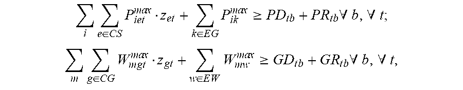
[0036] In addition, the generation capacity and air source capacity in the system of each year t after the energy storage device is programmed shall be larger than the load, which meets the following constraints:
i .times. e .di-elect cons. CS .times. P iet ma .times. .times. x z et + k .di-elect cons. E .times. G .times. P ik ma .times. .times. x .gtoreq. P .times. D tb + P .times. R tb .times. .A-inverted. b , .A-inverted. t ; ##EQU00005## m .times. g .di-elect cons. CG .times. W m .times. g .times. t ma .times. .times. x z g .times. t + w .di-elect cons. E .times. W .times. W m .times. w ma .times. .times. x .gtoreq. G .times. D t .times. b + G .times. R t .times. b .times. .A-inverted. b , .A-inverted. t , ##EQU00005.2##
where, P.sub.iet.sup.max refers to the capacity of battery e at power node i; P.sub.ik.sup.max refers to the generating capacity of generator set k at power node i; W.sub.mgt.sup.max refers to the capacity of gas storage device g at natural gas node m; W.sub.mw.sup.max refers to the gas production capacity of gas source W at natural gas node m; PD.sub.tb and GD.sub.tb refer to the power load and the natural gas load under state b of year t respectively; PR.sub.tb and GR.sub.tb refer to the power reserve capacity and the natural gas reserve capacity under state b of year t respectively.
[0037] II. Constraints for Natural Gas System:
[0038] During operation, the natural gas system needs to meet the following constraints, specifically as follows:
[0039] a. Constraints for Gas Flow Balance at Node:
[0040] In the system operation, the natural gas inflow and outflow at any node is the same, specifically expressed as:
w .di-elect cons. E .times. W .times. W mwtb + g .di-elect cons. CG .times. W mgtb - p .di-elect cons. GL .times. .tau. ptb - c .di-elect cons. GC .times. .tau. ctb = GD mtb - GLC mtb .times. .A-inverted. m , .times. .A-inverted. b , .A-inverted. t , ##EQU00006##
where, W.sub.mwtb refers to the gas output of gas source w at natural gas node m under state b of year t; W.sub.mwtb refers to the gas output of gas storage device g at natural gas node m under state b of year t; .tau..sub.ptb refers to the amount of natural gas flowing through pipeline p under state b of year t; .tau..sub.ctb refers to the amount of natural gas flowing through compressor C under state b of year t; GD.sub.mtb refers to the natural gas load at node m under state b of year t; GLC.sub.mtb refers to the natural gas load loss at node m under state b of year t; GC and GL refer to the collection of compressor and pipeline respectively.
[0041] b. Constraints for Pipeline Flow:
[0042] The amount of natural gas flowing through the pipeline is related to the air pressure at both ends, specifically expressed as:
(.sigma..sub.ptb.sup.+-.sigma..sub.ptb.sup.-)(.pi..sub.mtb-.pi..sub.ntb)- =.tau..sub.ptb.sup.2/M.sub.p .A-inverted.p.di-elect cons.GL,.A-inverted.b,.A-inverted.t,
where, .sigma..sub.ptb.sup.+ and .sigma..sub.ptb.sup.- refer to the marker for the flow direction of natural gas in pipeline p; .sigma..sub.ptb.sup.+=1 means that the natural gas in pipeline p flows from node m to node n; .sigma..sub.ptb.sup.-=1 means that the natural gas in pipeline flows from node n to node m; .pi..sub.mtb and .pi..sub.ntb refer to the gas pressure at node m and n under state b of year t respectively; M.sub.p refers to the fixed parameters of pipeline p.
[0043] The positions of markers for pipeline flow are binary variables and meet the following constraints:
.sigma..sub.ptb.sup.++.sigma..sub.ptb.sup.-=1 .A-inverted.p.di-elect cons.GL,.A-inverted.b,.A-inverted.t.
[0044] In addition, the pipeline flow needs to meet the following constraints:
-(1-.sigma..sub.ptb.sup.+).tau..sub.p.sup.max.ltoreq..tau..sub.ptb.ltore- q.(1-.sigma..sub.ptb.sup.-).tau..sub.p.sup.max .A-inverted.p.di-elect cons.GL,.A-inverted.b,.A-inverted.t,
where, .tau..sub.p.sup.max refers to the maximum natural gas flow in pipeline p.
[0045] c. Constraints for Compressor:
[0046] The air pressure at both ends of the compressor is related to the coefficient of compressor, specifically expressed as:
.GAMMA..sub.ctb=.pi..sub.cmtb/.pi..sub.cntb .A-inverted.c.di-elect cons.GC,.A-inverted.m,.A-inverted.b,.A-inverted.t,
where, .GAMMA..sub.ctb refers to the compressibility of compressor C under state b of year t; .pi..sup.cmtb and .pi..sub.ctnb refer to the air pressure at node m and node n of compressor c under state b of year t respectively.
[0047] In addition, the compressibility of compressor shall meet the following constraints:
.GAMMA..sub.c.sup.min.ltoreq..GAMMA..sub.ctb.ltoreq..GAMMA..sub.c.sup.ma- x .A-inverted.c.di-elect cons.GC,.A-inverted.m,.A-inverted.b,.A-inverted.t,
where, r.sub.c.sup.max and r.sub.c.sup.min refers to the maximum and minimum compressibility of compressor C respectively.
[0048] d. Constraints for the Output Capacity of Air Source:
[0049] The output capacity of air source shall meet the following constraints:
O.ltoreq.W.sub.mwtb.ltoreq.W.sub.mv.sup.maxo.sub.wtb .A-inverted.w.di-elect cons.EW,.A-inverted.m,.A-inverted.b,.A-inverted.t,
where, W.sub.mw.sup.max refers to the maximum output capacity of air source W at node m; o.sub.wtb refers to the running state of air source w under state b of year t.
[0050] e. Constraints for the Output of Gas Storage Device:
[0051] Gas storage device shall meet the following constraints:
-W.sub.mg.sup.maxz.sub.gt.ltoreq.W.sub.mgtb.ltoreq.W.sub.mg.sup.maxz.sub- .gt .A-inverted.g.di-elect cons.CG,.A-inverted.m,.A-inverted.b,.A-inverted.t,
where, W.sub.mg.sup.max refers to the maximum output of gas storage device g at node m.
[0052] f. Constraints for Natural Gas Load Loss:
[0053] The natural gas load loss at each node shall meet the following constraints:
GLC.sub.mtb.ltoreq.GD.sub.mtb .A-inverted.m,.A-inverted.b,.A-inverted.t.
[0054] III. Constraints for Electric Power System:
[0055] During operation, the electric power shall meet the following constraints, specifically as follows:
[0056] a. Constraints for Power Balance at Node:
[0057] At any power node, the power inflow is equal to the outflow, which is specifically expressed as:
e .di-elect cons. C .times. S .times. P ietb + k .di-elect cons. E .times. G .times. ( P iktb G .times. G + P iktb C .times. G ) - ( P .times. D itb - P .times. L .times. C itb ) = l .di-elect cons. E .times. L .times. f l .times. t .times. b .times. .A-inverted. i , .A-inverted. b , .A-inverted. t , ##EQU00007##
where, P.sub.ietb refers to the output power of battery e at power node i under state b of year t; P.sub.iktb.sup.GG refers to the output power of natural gas unit k at power node i under state b of year t; P.sub.iktb.sup.CG refers to the output power of coal-fired unit k at power node i under state b of year t; PLC.sub.itb refers to the power load loss at power node i under state b of year t; f.sub.ltb refers to the power of line l under state b of year t; EL refers to the collection of power line.
[0058] b. Constraints for Line Power:
[0059] The power flowing through the power line shall meet the following constraints:
f.sub.ltb.ltoreq.(.theta..sub.itb-.theta..sub.jtb)/x.sub.l .A-inverted.l.di-elect cons.EL,.A-inverted.b,.A-inverted.t,
where, .theta..sub.itb and .theta..sub.jtb refer to the directional angle of power node i and node j under state b of year t; x.sub.l refers to the impedance of line l.
[0060] In addition, the power flowing through the power line shall meet the following constraints:
-f.sub.l.sup.max.ltoreq.f.sub.ltb.ltoreq.f.sub.l.sup.max .A-inverted.l.di-elect cons.EL,.A-inverted.b,.A-inverted.t,
where, f.sub.l.sup.max refers to the power transmission capacity of line l.
[0061] c. Constraints for the Directional Angle of Node:
[0062] The directional angle of node shall meet the following constraints:
-.theta..sub.i.sup.max.ltoreq..theta..sub.itb.ltoreq..theta..sub.i.sup.m- ax .A-inverted.i,.A-inverted.b,.A-inverted.t,
where, .theta..sub.i.sup.max refers to the maximum value of the directional angle of node i.
[0063] d. Constraints for Battery Output Power:
[0064] The output power of battery shall meet the following constraints:
-P.sub.ie.sup.maxz.sub.et.ltoreq.P.sub.ietb.ltoreq.P.sub.ie.sup.max.sub.- et .A-inverted.e.di-elect cons.CS,.A-inverted.i,.A-inverted.b,.A-inverted.t.
[0065] e. Constraints for Generator Set Output Power:
[0066] The output power of coal-fired unit shall meet the following constraints:
O.ltoreq.P.sub.iktb.sup.CG.ltoreq.P.sub.ik.sup.maxo.sub.ktb .A-inverted.k.di-elect cons.EG,.A-inverted.i,.A-inverted.b,.A-inverted.t,
where, P.sub.ik.sup.max refers to the generating capacity of coal-fired unit at node i.
[0067] The output power of natural gas unit is related to the injected natural gas power, specifically expressed as:
P.sub.iktb.sup.GG=(GD.sub.mtb-GLC.sub.mtb) o.sub.ktb .A-inverted.b,.A-inverted.t,
where, refers to the caloricity of natural gas.
[0068] f. Constraints for Power Load Loss:
[0069] The power load loss at each node shall meet the following constraints:
PLC.sub.itb.ltoreq.PD.sub.itb .A-inverted.i,.A-inverted.b,.A-inverted.t.
[0070] IV. Constraints for Reliability:
[0071] The reliability of power-gas coupling system is usually measured by the average power load loss and the average natural gas load loss. The average power load loss can be calculated by the following formula:
EENS t = i .times. b .times. P .times. L .times. C itb D t .times. b , ##EQU00008##
where, refers to the average power load loss of year. Average power load loss shall meet the following constraints:
EENS.sub.t.ltoreq.EENS.sup.limit,
where, refers to the upper limit of average power load loss of year, which can be given by the programmer.
[0072] The average natural load loss can be calculated by the following formula:
EGN .times. S t = m .times. b .times. G .times. L .times. C m .times. t .times. b D t .times. b , ##EQU00009##
where, EGNS.sub.t refers to the average natural gas load loss of year t. Average natural gas load loss shall meet the following constraints:
EGNS.sub.t.ltoreq.EGNS.sup.limit,
where, EGNS.sup.limit refers to the upper limit of average natural gas load loss of year t, which can be given by the programmer.
Embodiment 2
[0073] In order to verify and illustrate the technical effect adopted in this method, this embodiment compare the method for programming the energy storage device in power-gas coupling system in traditional technical solution with the present invention, so as to verify the real effect of this method.
[0074] Taking the power-gas coupling system as an example, we define the reliability constraints EENS.sup.limit and EGNS.sup.limit and are respectively 10000 MWh and 2.times.10.sup.5 m.sup.3. The model proposed by the present invention and the model of the traditional method are used to programme the system. Based on the programming results, the reliability analysis of the programmed system is carried out, and the analysis results are shown in the following table.
TABLE-US-00001 Reliability parameters Reliability parameters of electric power of natural gas system system EENS EGNS Traditional method 8.5 .times. 10.sup.5 m.sup.3 95000 MWh The method presented 1.3 .times. 10.sup.5 m.sup.3 9000 MWh in the present invention
[0075] As shown from the above analysis results, the reliability indexes EENS and EGNS obtained by the programming through traditional method are much higher than the reliability constraint indexes EENS.sup.limit and EGNS.sup.limit, indicating that the programming results of the traditional method cannot guarantee the reliable operation of the system. On the contrary, the reliability indexes EENS and EGNS obtained by the present invention are far less than the reliability constraint indexes, indicating that the method proposed by the present invention can ensure the reliability requirements of the system.
* * * * *
D00000
D00001
D00002
D00003


XML
uspto.report is an independent third-party trademark research tool that is not affiliated, endorsed, or sponsored by the United States Patent and Trademark Office (USPTO) or any other governmental organization. The information provided by uspto.report is based on publicly available data at the time of writing and is intended for informational purposes only.
While we strive to provide accurate and up-to-date information, we do not guarantee the accuracy, completeness, reliability, or suitability of the information displayed on this site. The use of this site is at your own risk. Any reliance you place on such information is therefore strictly at your own risk.
All official trademark data, including owner information, should be verified by visiting the official USPTO website at www.uspto.gov. This site is not intended to replace professional legal advice and should not be used as a substitute for consulting with a legal professional who is knowledgeable about trademark law.