Universal Heat Exchanger
YAMAMOTO; Yuji ; et al.
U.S. patent application number 17/428662 was filed with the patent office on 2022-04-21 for universal heat exchanger. The applicant listed for this patent is PRANAV VIKAS INDIA PVT LIMITED. Invention is credited to Sanjay Chawla, Dakshinamurthy Govindaraj, Poonam Hyanki, Vijayaraghavan. S., K Srinivas, Hemanshu Yadav, Yuji YAMAMOTO.
| Application Number | 20220120506 17/428662 |
| Document ID | / |
| Family ID | |
| Filed Date | 2022-04-21 |


View All Diagrams
| United States Patent Application | 20220120506 |
| Kind Code | A1 |
| YAMAMOTO; Yuji ; et al. | April 21, 2022 |
UNIVERSAL HEAT EXCHANGER
Abstract
A heat exchanger (100) having a plurality of plates (101) manufactured preferably but not limiting to the stamping process, the plates has been configured to accommodate the internal fins (106). The plates (101) also define plurality of the passages (102) for flowing at least two fluids. A plurality of conduits (103) fluidly coupled to a first end and second of the end of the plates (101) which allows the flow of the fluids. At least one inlet (104) coupled to a first end, and at least one outlet (105) coupled to the second end of the plurality of plates (101) configured to allow the flow of the fluids wherein each fluid flow in a different direction from the other, a plurality of inner fins (106) disposed on a surface of each of the plurality of plates (101) for increasing the surface to volume ratio of the first and second fluid to achieve pre-defined thermal performance.
| Inventors: | YAMAMOTO; Yuji; (Faridabad, Haryana, IN) ; Chawla; Sanjay; (Faridabad, Haryana, IN) ; Yadav; Hemanshu; (Faridabad, Haryana, IN) ; Hyanki; Poonam; (Faridabad, Haryana, IN) ; S.; Vijayaraghavan.; (Faridabad, Haryana, IN) ; Govindaraj; Dakshinamurthy; (Faridabad, Haryana, IN) ; Srinivas; K; (Faridabad, Haryana, IN) | ||||||||||
| Applicant: |
|
||||||||||
|---|---|---|---|---|---|---|---|---|---|---|---|
| Appl. No.: | 17/428662 | ||||||||||
| Filed: | March 19, 2019 | ||||||||||
| PCT Filed: | March 19, 2019 | ||||||||||
| PCT NO: | PCT/IN2019/050222 | ||||||||||
| 371 Date: | August 5, 2021 |
| International Class: | F28D 9/00 20060101 F28D009/00; F28F 3/02 20060101 F28F003/02; F28F 3/08 20060101 F28F003/08 |
Foreign Application Data
| Date | Code | Application Number |
|---|---|---|
| Feb 5, 2019 | IN | 201911004537 |
Claims
1) A heat exchanger (100) comprising: a plurality of plates (101) configured to define a plurality of flow passages for flowing at least two fluids; a plurality of conduits fluidly coupled to a first end and a second end of the plates to allow the flow of the fluids; at least one inlet coupled to the first end, and at least one outlet coupled to the second end of the plurality of plates configured to allow the flow of the fluids wherein each fluid flow in a different direction from the other; a plurality of inner fins disposed on a surface of each of the plurality of plates for increasing the surface to volume ratio of the first and second fluid to achieve pre-defined thermal performance.
2) The heat exchanger as claimed in claim 1, wherein the fluids flow in the opposite direction from the other.
3) The heat exchanger as claimed in claim 1, wherein the fluids are either a refrigerant or a coolant.
4) The heat exchanger as claimed in claim 1, wherein the plurality of the inner fins are non-louvered straight wavy fins configured to produce laminar flow.
5) The heat exchanger as claimed in claim 1, wherein the inner fins are disposed on the plain plate area.
6) The heat exchanger as claimed in claim 1, wherein the plurality of plates are dumbbell-shaped stamped plates capable to interlock while stacking on each other.
7) The heat exchanger as claimed in claim 1, wherein the plurality of plates are having a pre-defined specific thickness.
8) The heat exchanger as claimed in claim 1, wherein a stiffener is placed in one of the plates of the heat exchanger for high-pressure application.
9) The heat exchanger as claimed in claim 1, wherein the plate has a plurality of embossing and a plurality of fin stoppers.
10) The heat exchanger as claimed in claim 1, wherein the heat exchanger work as three different heat exchangers such as Chiller or W-Condenser or Plate IHX as per the requirement by changing the inlet/outlet connections with a common core.
Description
FIELD OF THE INVENTION
[0001] The present invention generally relates to heat exchangers. In particular, the invention relates to heat exchangers for automobiles. More particularly, the invention relates to a heat exchanger that can be used for low-pressure applications as well as for high-pressure applications.
BACKGROUND OF THE INVENTION
[0002] Batteries play an important role in powering all types of electric vehicles. Nowadays, there is a growing demand for lithium-ion batteries in various applications, particularly for electric vehicles, which require a more reliable battery thermal management system for controlling the battery temperature. Due to their high energy density, low self-discharge rate, and long cycle life, lithium-ion batteries are the main source of power in electric vehicles. The thermal safety of lithium-ion batteries during their application has become the main issue. In the past few years, researchers and automotive manufacturers have been focusing on the cooling of Li-ion batteries as this is a major obstacle in the development of electric vehicles.
[0003] In addition, one of the limitations of the battery is with regard to thermal control. When the battery is operated at a low temperature, the power output will be reduced due to the suppression of the electrochemical reactions, while a high temperature will accelerate corrosion, thus leading to reduced battery life. Other than that, the temperature range and uniformity in a pack are significant factors for obtaining optimum performance from an EV battery pack. An excessive rise in the local temperature in Li-ion batteries will cause a reduction in the life cycle and may lead to the occurrence of thermal runaway in an individual cell or in the entire battery pack. Thermal runaway is a failure mode in the battery and it may cause a fire and an explosion if the thermal management system in the battery is ineffective. Therefore, it is necessary to introduce a cooling method for the Li-ion battery to ensure that it has an effective thermal management system. There are several types of cooling methods for Li-ion batteries such as air cooling, liquid cooling and the use of phase change materials. Air cooling is widely used as a cooling method in order to ensure that the Li-ion battery is safe, reliable and has a long operating life. In addition, temperature uniformity in the battery module can be improved by using the air cooling method. This method has its limitations, and it is suitable for a low energy density Li-ion battery. If the battery has a high energy density, then a liquid cooling system provides the most effective thermal management.
[0004] A Chiller is used in electric vehicles for cooling the battery. The Chiller is a heat exchanger which is used to remove heat from the battery and passing it to the refrigerant to sink the heat to the atmosphere. A water-cooled condenser or W-condenser can be used in electric vehicles (EV's) for cabin heating. It also increases sub-cooling of refrigerant in the refrigerant circuit. An IHX is a liquid to vapor heat exchanger. IHX transfers heat from the liquid refrigerant (After condenser) to vapor refrigerant (After evaporator). IHX sub-cools refrigerant from condenser further below condensation temperature. It also prevents liquid refrigerant to enter into the compressor. Also, IHX is being used today is to get away with using less refrigerant. Plate IHX (Internal Heat Exchanger) will improve the efficiency and packaging space as compared to existing tubular type IHX. Plate IHX can also be used in ICE automobiles.
[0005] However, these heat exchangers face various problems such as limited space available in the vehicle engine compartment, high thermal performance requirements, less development time for the non-standard designs, less tooling cost demand due to competition, less part weight as a part of light weighting programs for better vehicle performance and fuel efficiency, less part cost to be competitive in the market, development of large number of child parts, heavy components to meet the structural/Integrity requirements.
Objective of the Invention
[0006] The object of the invention is to provide on a universal heat exchanger design for three different applications Chiller (Low-Pressure Application), w-condenser (High-Pressure Application) and plate IHX (High-Pressure Application).
[0007] Another object of the invention is to provide an inner fin in plate heat exchanger applications such as a chiller, W-condenser, and Plate IHX heat exchangers.
[0008] Another object of the invention is to provide internal fins to increase the surface to volume ratio for both coolant and refrigerant for high thermal performance.
[0009] Another object of the invention is to provide the shape of the plates to accommodate inner fins for high-pressure applications.
[0010] Another object of the invention is to provide a heat exchange which works with counterflow between coolant and refrigerant for high thermal performance.
[0011] Another object of the invention is to provide a light and compact heat exchanger for better vehicle performance and fuel efficiency.
[0012] Another object of the invention is to provide stamped plates with a new design to increase the bulge and burst pressure of the heat exchangers.
[0013] Another object of the invention is to provide a heat exchanger with no internal leakage or intermixing of two fluids in the heat exchanger.
SUMMARY OF THE INVENTION
[0014] The present invention relates to a heat exchanger comprising a plurality of plates configured to define a plurality of flow passages for flowing at least two fluids, a plurality of conduits fluidly coupled to a first end and a second end of the plates to allow the flow of the fluids, at least one inlet coupled to the first end, and at least one outlet coupled to the second end of the plurality of plates configured to allow the flow of the fluids wherein each fluid flow in a different direction from the other, preferably the fluids flow in the opposite direction from the other, a plurality of inner fins disposed on a surface of each of the plurality of plates for increasing the surface to volume ratio of the first and second fluid to achieve pre-defined thermal performance.
[0015] In an embodiment, the fluids are either a refrigerant or a coolant.
[0016] In an embodiment, the plurality of the inner fins are non-louvered straight wavy fins configured to produce laminar flow. Preferably, the inner fins are disposed on the plain plate area.
[0017] In an embodiment, the plurality of plates are dumbbell-shaped stamped plates capable to interlock while stacking on each other. Preferably, the plurality of plates are having a pre-defined specific thickness.
[0018] In an embodiment, a stiffener is placed in one of the plates of the heat exchanger for the high-pressure application.
[0019] In an embodiment, the plate has a plurality of embossing and a plurality of fin stoppers.
[0020] In an embodiment, the heat exchanger works as three different heat exchangers such as Chiller or W-Condenser or Plate IHX as per the requirement by changing the inlet/outlet connections with a common core.
BRIEF DESCRIPTION OF ACCOMPANYING DRAWINGS
[0021] The foregoing and further objects, features, and advantages of the present subject matter will become apparent from the following description of exemplary embodiments with reference to the accompanying drawings, wherein like numerals are used to represent like elements.
[0022] It is to be noted, however, that the appended drawings illustrate only typical embodiments of the present subject matter, and are, therefore, not to be considered for limiting of its scope, for the subject matter may admit to other equally effective embodiments.
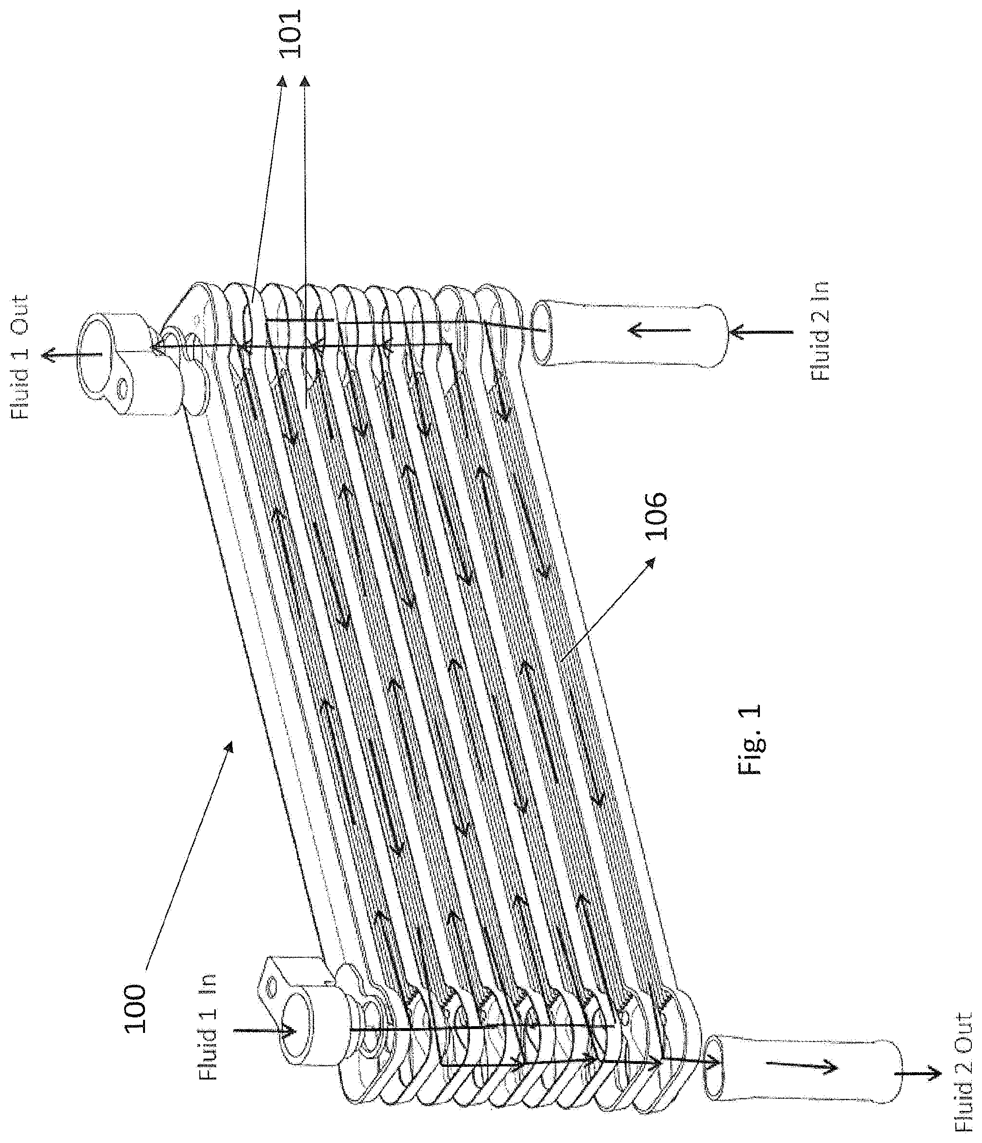
[0023] FIG. 1. illustrates the exploded view of the present invention with both fluids flow direction in accordance with one embodiment of the present subject matter;
[0024] FIG. 2(a). illustrates the perspective view of the present invention in accordance with one embodiment of the present subject matter;
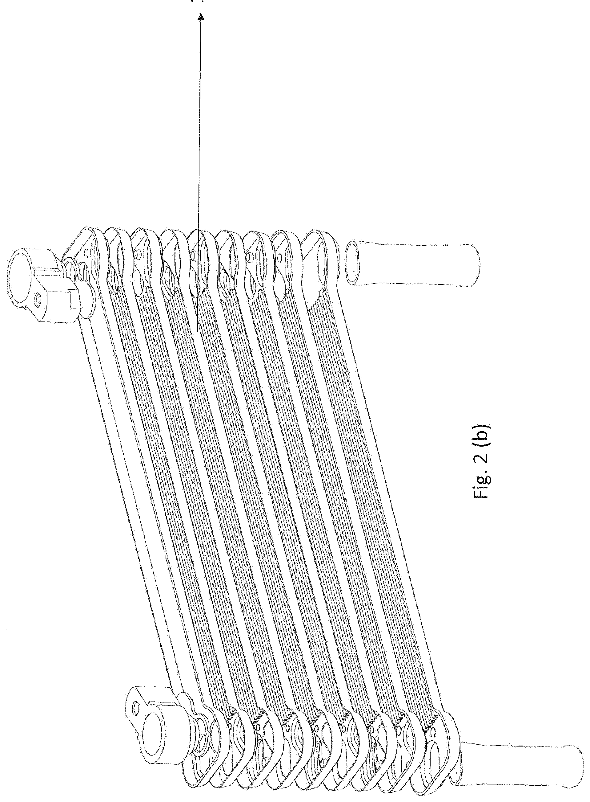
[0025] FIG. 2(b). illustrates the exploded view of the present invention Chiller in accordance with one embodiment of the present subject matter;
[0026] FIG. 2(c). illustrates the exploded view of the present invention w-condenser in accordance with one embodiment of the present subject matter;
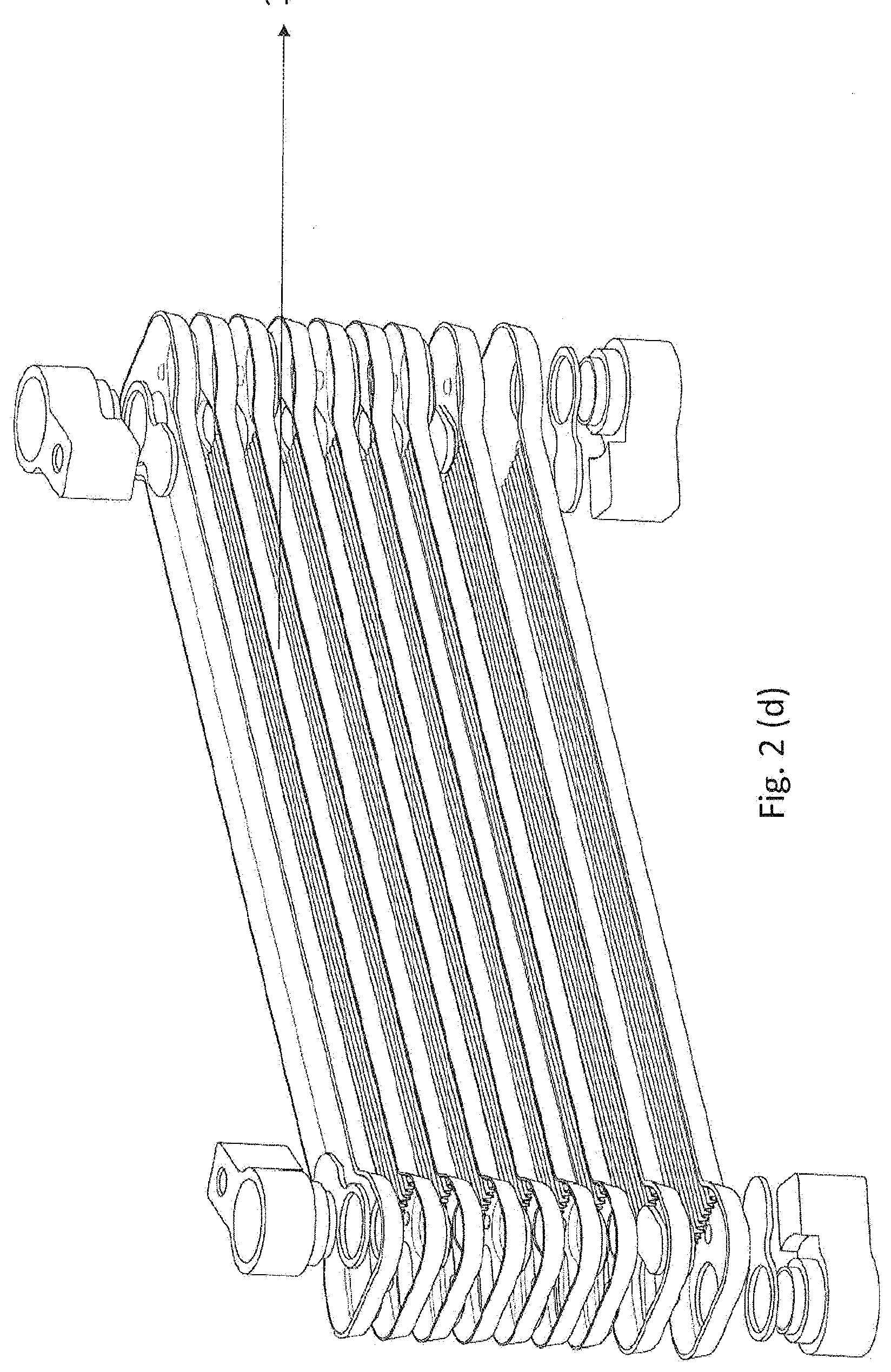
[0027] FIG. 2(d). illustrates the exploded view of the present invention plate IHX in accordance with one embodiment of the present subject matter;
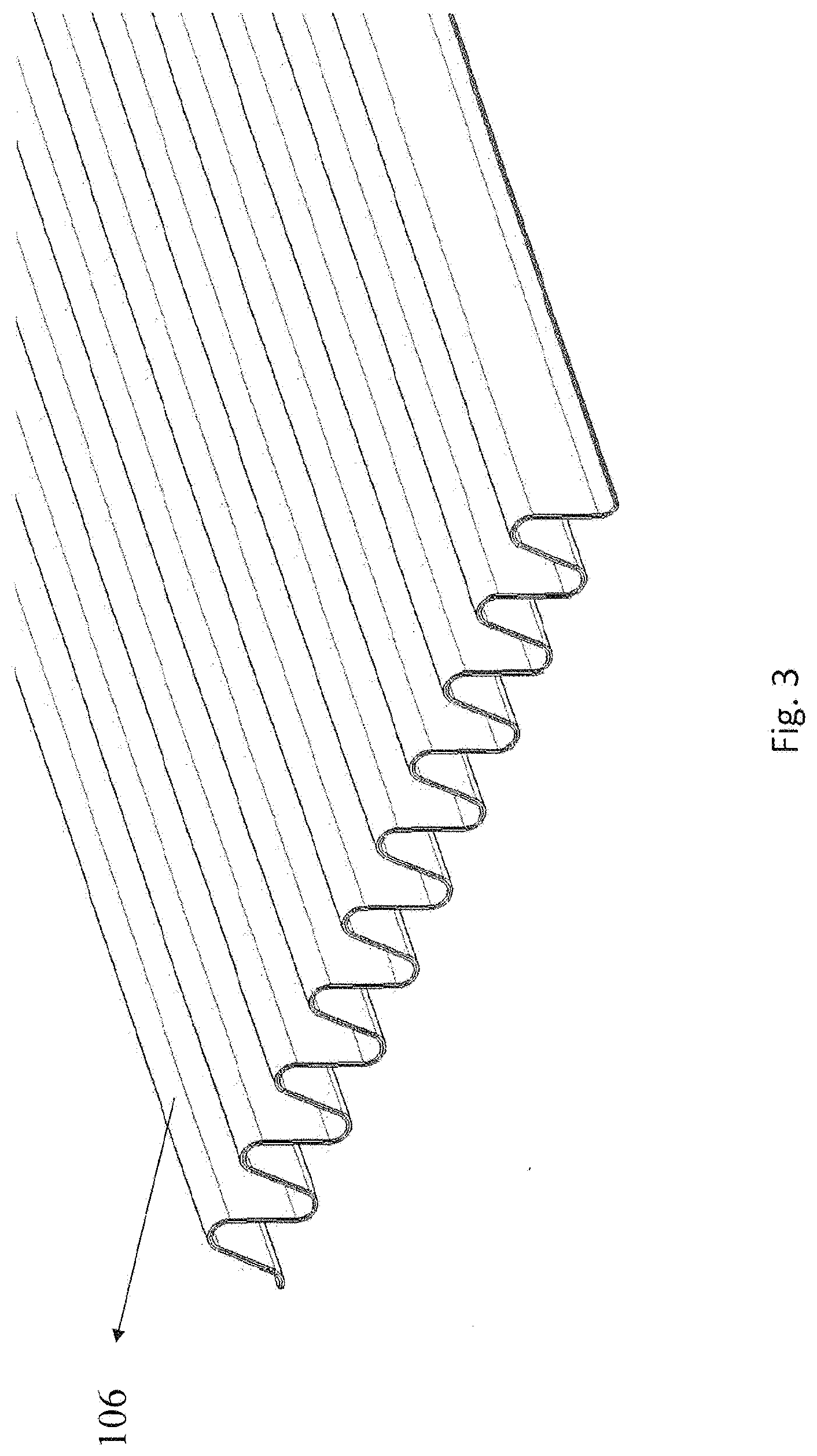
[0028] FIG. 3. illustrates the inner fins of the present invention in accordance with one embodiment of the present subject matter;
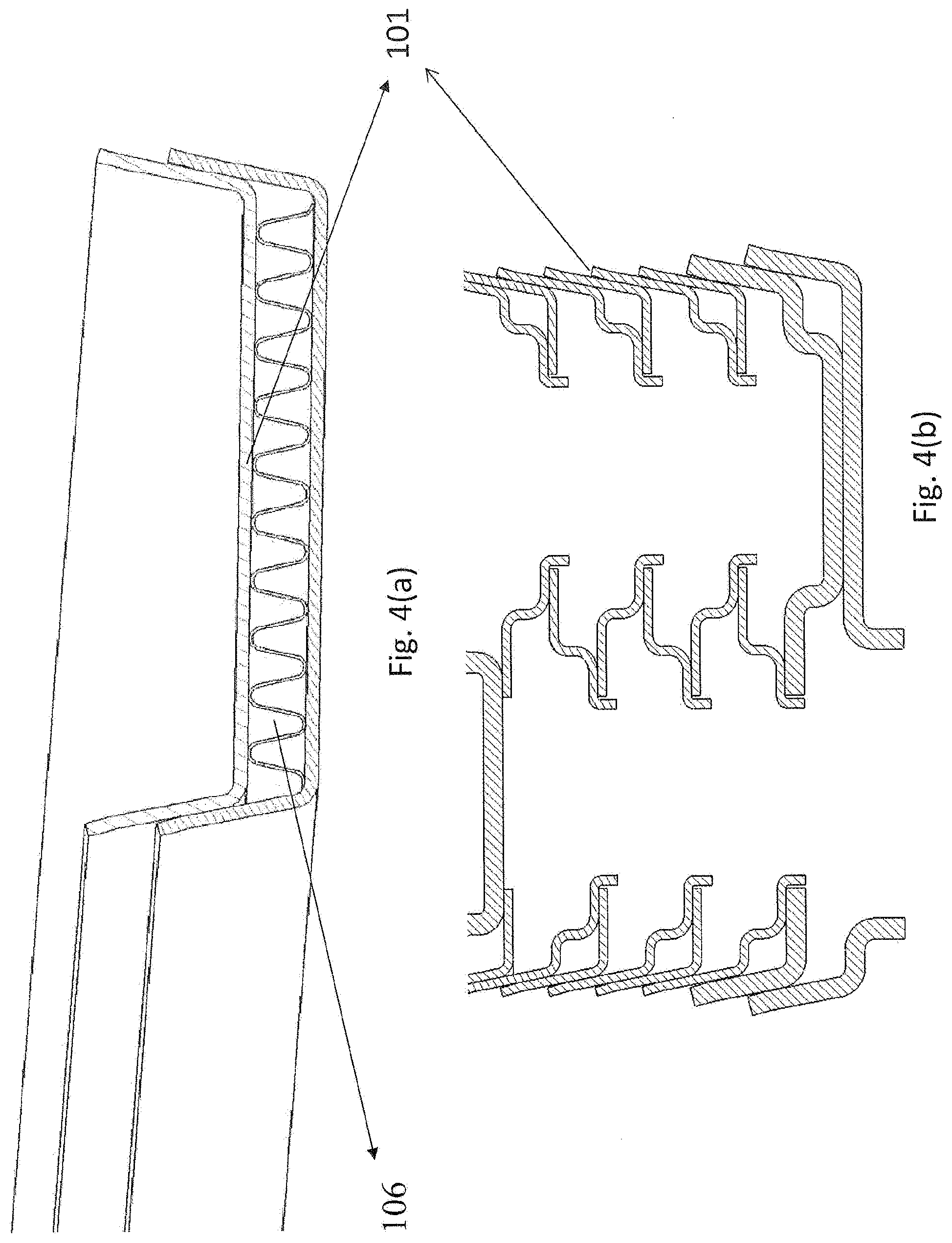
[0029] FIG. 4(a). illustrates the perspective view of the inner fins between the plates in accordance with one embodiment of the present subject matter;
[0030] FIG. 4(b). illustrates the front view of the interlocked plates in accordance with one embodiment of the present subject matter;
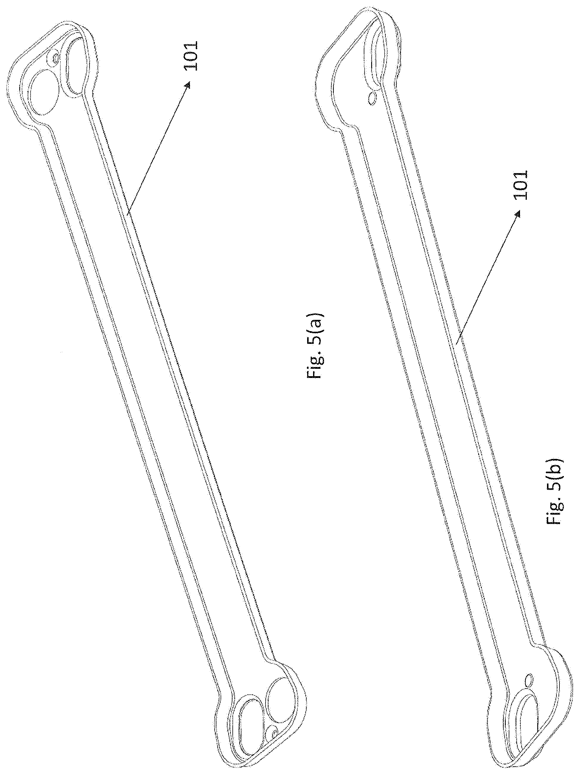
[0031] FIG. 5(a). illustrates the perspective view of the plate in accordance with one embodiment of the present subject matter;
[0032] FIG. 5(b). illustrates the perspective view of the plate in accordance with one embodiment of the present subject matter;
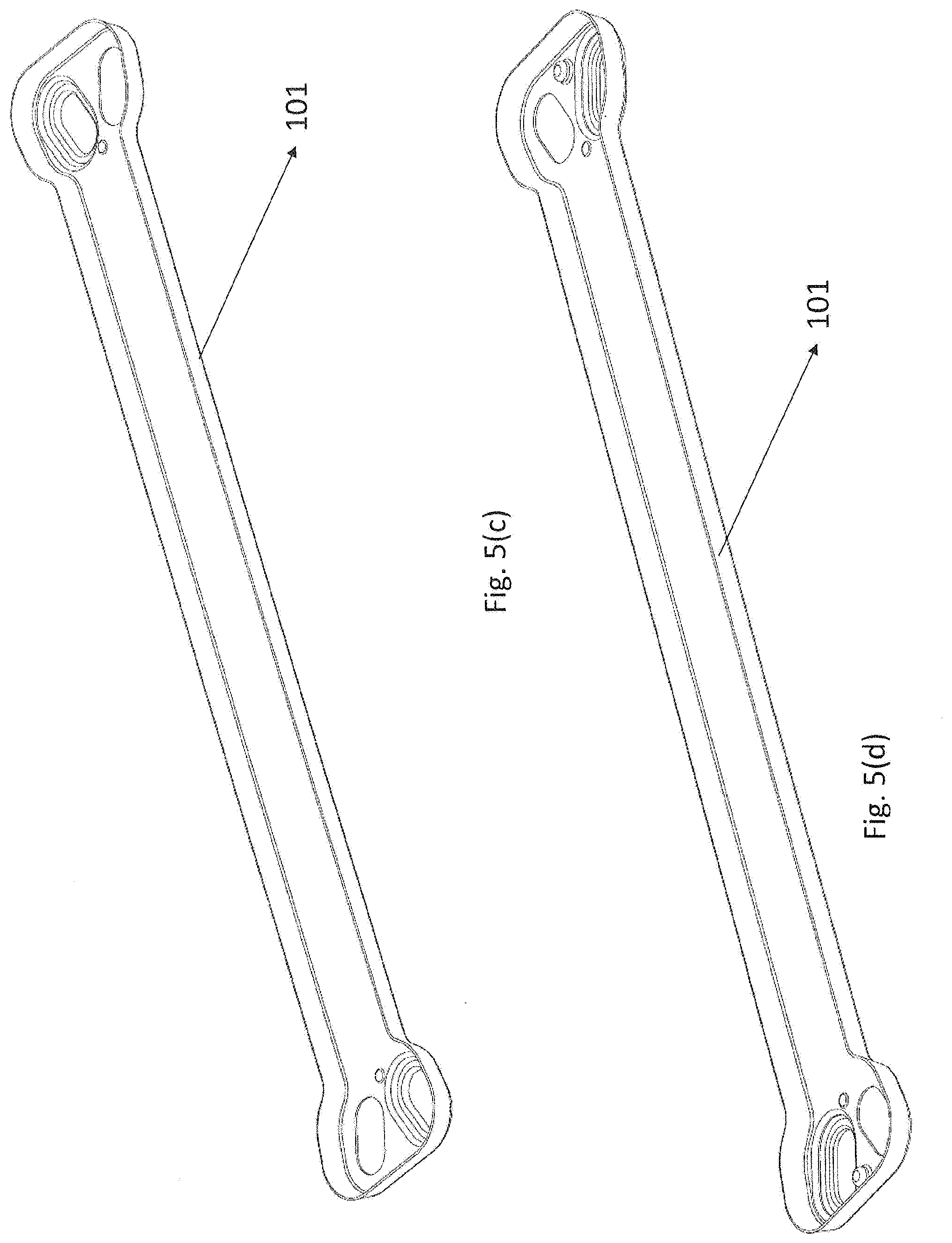
[0033] FIG. 5(c). illustrates the perspective view of the plate in accordance with one embodiment of the present subject matter;
[0034] FIG. 5(d). illustrates the perspective view of the plate in accordance with one embodiment of the present subject matter;
[0035] FIG. 5(e). illustrates the perspective view of the plate in accordance with one embodiment of the present subject matter;
[0036] FIG. 6. illustrates the perspective view of the plate along with the internal fins in accordance with one embodiment of the present subject matter;
[0037] FIG. 7. illustrates the cut view of the stacked plates along with the internal fins in accordance with one embodiment of the present subject matter;
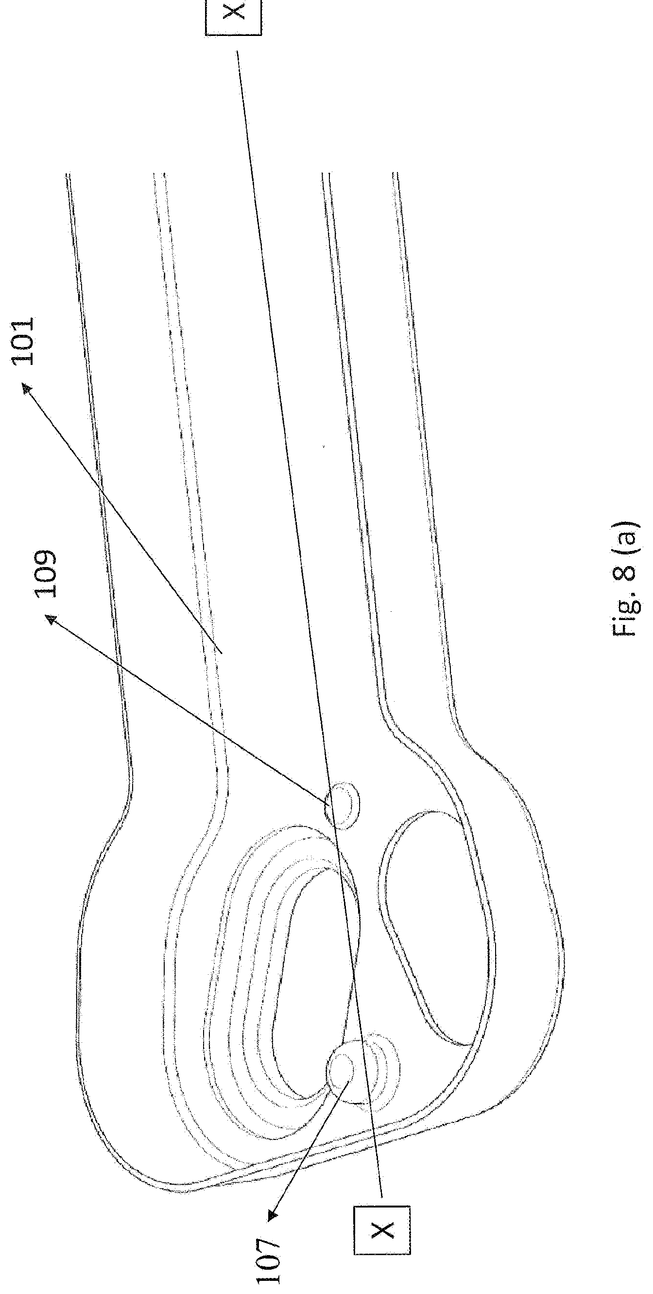
[0038] FIG. 8(a). illustrates the plate along with embossing and stopper in accordance with one embodiment of the present subject matter;
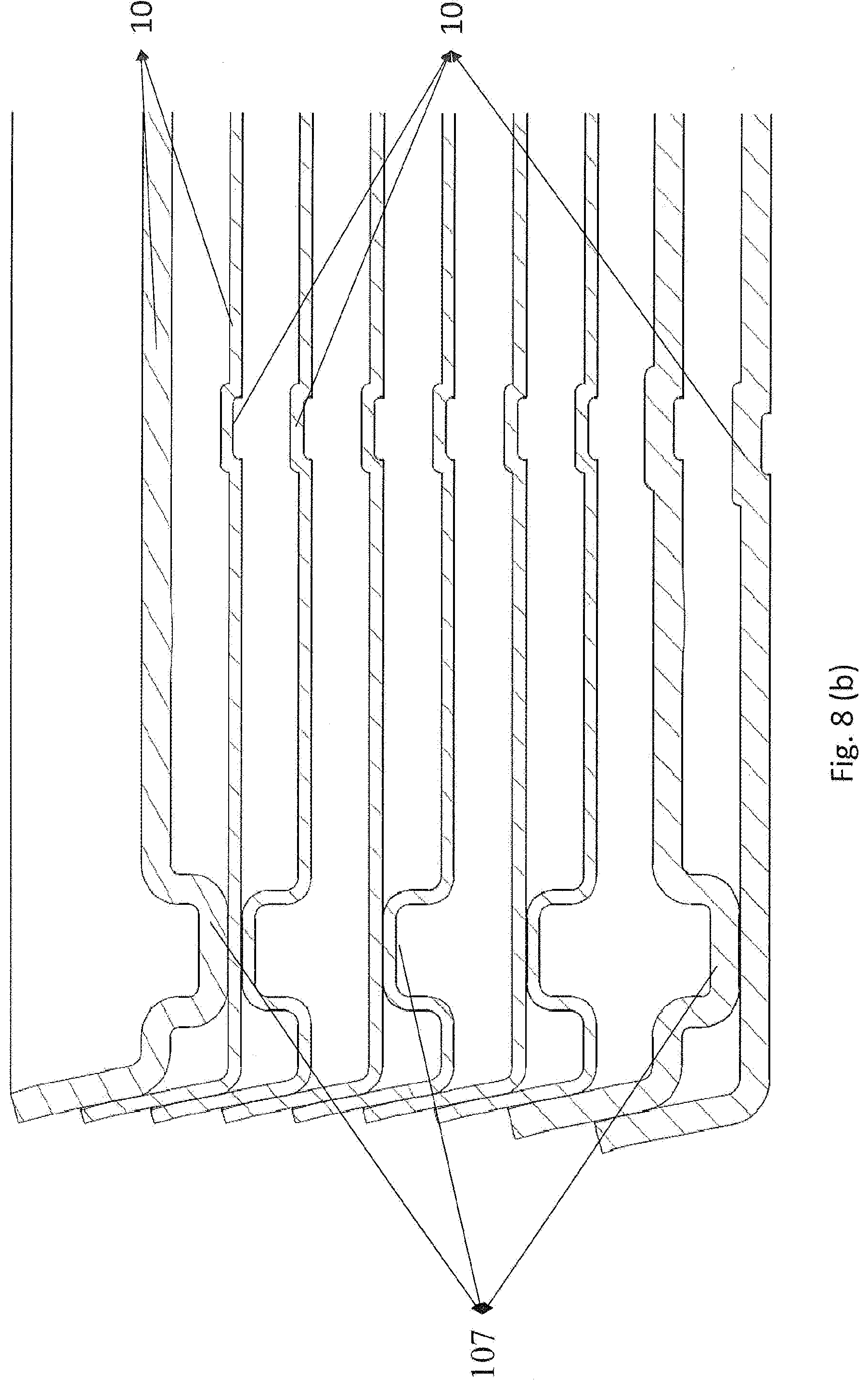
[0039] FIG. 8(b). illustrates the Section X-X showing plate embossing with fin stopper in accordance with one embodiment of the present subject matter;
[0040] FIG. 9. illustrates the plate using a stiffener for the high-pressure application.
DETAILED DESCRIPTION
[0041] The following presents a detailed description of various embodiments of the present subject matter with reference to the accompanying drawings.
[0042] The embodiments of the present subject matter are described in detail with reference to the accompanying drawings. However, the present subject matter is not limited to these embodiments which are only provided to explain more clearly the present subject matter to a person skilled in the art of the present disclosure. In the accompanying drawings, like reference numerals are used to indicate like components.
[0043] The specification may refer to "an", "one", "different" or "some" embodiment(s) in several locations. This does not necessarily imply that each such reference is to the same embodiment(s), or that the feature only applies to a single embodiment. Single features of different embodiments may also be combined to provide other embodiments.
[0044] As used herein, the singular forms "a", "an" and "the" are intended to include the plural forms as well, unless expressly stated otherwise. It will be further understood that the terms "includes", "comprises", "including" and/or "comprising" when used in this specification, specify the presence of stated features, integers, steps, operations, elements, and/or components, but do not preclude the presence or addition of one or more other features, integers, steps, operations, elements, components, and/or groups thereof. It will be understood that when an element is referred to as being "attached" or "connected" or "coupled" or "mounted" to another element, it can be directly attached or connected or coupled to the other element or intervening elements may be present. As used herein, the term "and/or" includes any and all combinations and arrangements of one or more of the associated listed items.
[0045] The figures depict a simplified structure only showing some elements and functional entities, all being logical units whose implementation may differ from what is shown.
[0046] FIG. 1 shows the exploded view of the present invention, wherein it shows a heat exchanger (100) having a plurality of plates (101) manufactured preferably but not limiting to the stamping process, the plates have been configured to accommodate the internal fins (106). The plates (101) also define a plurality of the passages (102) for following at least two fluids. A plurality of conduits (103) fluidly coupled to a first end and second of the end of the plates (101) which allows the flow of the fluids. At least one inlet (104) coupled to a first end, and at least one outlet (105) coupled to the second end of the plurality of plates (101) configured to allow the flow of the fluids wherein each fluid flow in a different direction from the other, a plurality of inner fins (106) disposed on a surface of each of the plurality of plates (101) for increasing the surface to volume ratio of the first and second fluid to achieve pre-defined thermal performance. The fluids flow in the opposite direction creates a counter flow. For counter flow between two fluids, inlet-outlet ports are positioned diagonally opposite in each plate. Such that both fluids flow in reverse direction on both sides of a plate
[0047] This particular configuration of the heat exchanger (100) is focused on the development of three heat exchangers by using Plate and Fin (PAF) concept with the counterflow for BCS, EVTMS Circuits and ICE Automobiles. Changing requirements and constraints demands significant flexibility in these heat exchanger (100) designs in terms of thermal performance, refrigerant distribution uniformity, non-standard aspect ratio (width/height of HEX), varying refrigerant flow structure (multipass), development time and cost.
[0048] FIG. 2 (a) shows the perspective view of the present invention, this particular figure shows a chiller assembly of the heat exchanger (100). The plates (101) are stacked together which make the heat exchanger (100) very compact. The plates (101) may be varied by the user depending on the application/thermal performance requirement of the heat exchanger (100). The compact nature of the heat exchanger (100) tends to be installed in any small to medium size vehicles.
[0049] FIGS. 2(b), 2(c) and 2(d) illustrate a various configuration which provides a multifunctional heat exchanger (HEX)(100) which can be used for different pressure applications. A single design concept is used for three different heat exchanger applications by simply changing the inlet/outlet connections with a common core. That means fewer inventories, lowest wastages, high quality, less tooling cost, less development time and cost, and lower design, material, and process related issues. Counterflow between two fluids for maximum heat transfer.
TABLE-US-00001 Heat Exchanger Flow medium-1 Flow medium- 2 Chiller Low pressure and low- Low pressure and high- temperature refrigerant temperature coolant W-Condenser High pressure and high- Low pressure and low- temperature refrigerant temperature coolant P-IHX Low pressure and low- High pressure and high- temperature refrigerant temperature refrigerant
[0050] FIG. 3. shows the inner fins (106) which are accommodated between the plates (101). The internal fins (106) are designed to accommodate the fins (106) between the plates (101) which enhances high-pressure withstanding capability. The plurality of the inner fins (106) are non-louvered straight wavy fins (106) configured to produce laminar flow. Preferably, the inner fins (106) are disposed on the plain plate area. They are preferably formed through a stamping process.
[0051] FIGS. 4(a) and 4(b) shows the perspective and front view of the inner fins (106) between the plates (101). The plates (101) are configured to accommodate the internal fins (106), the plates (101) are so formed that to allow the passage of the fluids through them. The plates (101) are also interlocked which avoid leakage of the fluids and intermixing of the two fluids.
[0052] FIG. 5(a), 5(b), 5(c), 5(d) and 5(e) shows the perspective view of the stamped plate designs in accordance with one embodiment of the present invention. These five different types of plates are used in the development of all three heat exchangers. Preferably but not limiting between 0.3 mm to 1 mm plate thickness is used in the development of chiller, W-condenser and Plate IHX to make it a light and compact heat exchanger (100) as a future heat exchanger (100) technology for better vehicle performance and fuel efficiency. The different thermal performance requirements can be easily achieved by simply changing the number of plates (101) and fin stacks or by changing a number of passes. The plates (101) are so configured to accommodate the inner fins (106). The plates (101) are preferably but not limited to have a dumbbell-shaped stamped plates (101) which are capable to interlock while stacking on each other.
[0053] FIG. 6 shows the plate along with the internal fins (106). The inner fins (106) are usually disposed on the plain portion of the plate. The fins (106) are so disposed that they are entirely within the space provided over the plate. The interlocking of the plates (101) does not deform the original shape of the internal fins (106). The plates (101) have the passages and the inlet and outlet ports which allow fluids to flow through them. The ports are of the nature that it can close through a stopper on basis of their applications.
[0054] FIG. 7 shows the cut view of the stacked plates (101) along with the internal fins (106) in accordance with one embodiment of the present subject matter. The plates (101) are so configured to interlock, the dumbbell shape of the plates (101) helps the plates (101) to be stacked and provide interlocking. Interlocking dumbbell shape stamped plates (101) are used to increase the bulge and burst pressure of the heat exchangers. It is achieved by optimizing the unsupported area between internal fins (106) and I/O holes for a plate.
[0055] FIG. 8(a) the plate along with embossing (107) and fin stopper (109) in accordance with one embodiment of the present subject matter. Embossing (107) is used to increase the bulge and burst pressure of the heat exchanger. Fin stopper (109) is used to stop the fin movement along the core length.
[0056] FIG. 8(b) shows a section view of the plates in the heat exchanger assembly. FIG. 8(b) clearly shows how embossings are brazed to the adjacent plates to increase the bulge and burst pressure of the heat exchanger by reducing the unsupported area of the plates for pressure load.
[0057] FIG. 9 shows the plate with a stiffener (108) for the high-pressure application. Stiffener and increased thickness are necessary for withstanding high-pressure loads in the localized area. For high-pressure application in W-condenser and Plate IHX, a stiffener is placed in one of the plates (101), preferably but not limited to second last plate of the heat exchanger (100) to meet the high burst pressure requirements of these two heat exchangers
[0058] Although the invention has been described with reference to specific embodiments, this description is not meant to be construed in a limiting sense. Various modifications of the disclosed embodiments, as well as alternate embodiments of the invention, will become apparent to persons skilled in the art upon reference to the description of the invention. It is, therefore, contemplated that such modifications can be made without departing from the spirit or scope of the present invention as defined.
* * * * *
D00000
D00001
D00002
D00003
D00004
D00005
D00006
D00007
D00008
D00009
D00010
D00011
D00012

D00013
D00014
D00015

XML
uspto.report is an independent third-party trademark research tool that is not affiliated, endorsed, or sponsored by the United States Patent and Trademark Office (USPTO) or any other governmental organization. The information provided by uspto.report is based on publicly available data at the time of writing and is intended for informational purposes only.
While we strive to provide accurate and up-to-date information, we do not guarantee the accuracy, completeness, reliability, or suitability of the information displayed on this site. The use of this site is at your own risk. Any reliance you place on such information is therefore strictly at your own risk.
All official trademark data, including owner information, should be verified by visiting the official USPTO website at www.uspto.gov. This site is not intended to replace professional legal advice and should not be used as a substitute for consulting with a legal professional who is knowledgeable about trademark law.