Method For Manufacturing A Part From Aluminium Alloy, The Alloy Comprising At Least Zirconium And Magnesium
CHEHAB; Bechir ; et al.
U.S. patent application number 17/424671 was filed with the patent office on 2022-04-21 for method for manufacturing a part from aluminium alloy, the alloy comprising at least zirconium and magnesium. The applicant listed for this patent is C-TEC CONSTELLIUM TECHNOLOGY CENTER. Invention is credited to Bechir CHEHAB, Ravi SHAHANI.
| Application Number | 20220119926 17/424671 |
| Document ID | / |
| Family ID | 1000006104032 |
| Filed Date | 2022-04-21 |


| United States Patent Application | 20220119926 |
| Kind Code | A1 |
| CHEHAB; Bechir ; et al. | April 21, 2022 |
METHOD FOR MANUFACTURING A PART FROM ALUMINIUM ALLOY, THE ALLOY COMPRISING AT LEAST ZIRCONIUM AND MAGNESIUM
Abstract
An object of the invention is a method for manufacturing a part including a formation of successive metallic layers (20.sub.1, . . . 20.sub.n), superimposed on one another, each layer being formed by the deposition of a filler metal (15, 35), the filler metal being subjected to an energy supply so as to melt and constitute, when solidifying, said layer, the method being characterized in that the filler metal (15, 35) is an aluminum alloy including the following alloy elements, in weight percents: Mg: 0%-6%; Zr: 0.7%-2.5%, preferably according to a first variant >1% and .ltoreq.2.5%; or preferably according to a second variant 0.7-2%; and possibly 0.7-1.6%; and possibly 0.7-1.4%; and possibly 0.8-1.4%; and possibly 0.8-1.2%; at least one alloy element selected from Fe, Cu, Mn, Ni and/or La: at least 0.1%, preferably at least 0.25%, more preferably at least 0.5% per element; impurities: <0.05% individually, and preferably <0.15% all in all.
| Inventors: | CHEHAB; Bechir; (Voiron, FR) ; SHAHANI; Ravi; (Voreppe, FR) | ||||||||||
| Applicant: |
|
||||||||||
|---|---|---|---|---|---|---|---|---|---|---|---|
| Family ID: | 1000006104032 | ||||||||||
| Appl. No.: | 17/424671 | ||||||||||
| Filed: | January 24, 2020 | ||||||||||
| PCT Filed: | January 24, 2020 | ||||||||||
| PCT NO: | PCT/FR2020/050107 | ||||||||||
| 371 Date: | July 21, 2021 |
| Current U.S. Class: | 1/1 |
| Current CPC Class: | B33Y 70/00 20141201; C22C 21/06 20130101; C22F 1/047 20130101; B23K 26/342 20151001; B33Y 40/20 20200101; B22F 10/28 20210101; B33Y 10/00 20141201; B22F 10/64 20210101; B22F 2301/052 20130101 |
| International Class: | C22C 21/06 20060101 C22C021/06; B33Y 10/00 20060101 B33Y010/00; B33Y 70/00 20060101 B33Y070/00; B22F 10/28 20060101 B22F010/28; B22F 10/64 20060101 B22F010/64; B33Y 40/20 20060101 B33Y040/20; C22F 1/047 20060101 C22F001/047; B23K 26/342 20060101 B23K026/342 |
Foreign Application Data
| Date | Code | Application Number |
|---|---|---|
| Jan 24, 2019 | FR | 1900598 |
Claims
1. A method for manufacturing a part comprising forming a formation of successive metallic layers, superimposed on one another, each layer being formed by the deposition of a filler metal, the filler metal being subjected to an energy supply so as to melt and constitute, when solidifying, said layer, wherein the filler metal is an aluminum alloy including the following alloy elements, in weight percent: Mg: 0%-6%; Zr: 0.7%-2.5%, optionally according to a first variant >1% and .ltoreq.2.5%; or optionally according to a second variant 0.7-2%; and optionally 0.7-1.6%; and optionally 0.7-1.4%; and optionally 0.8-1.4%; and optionally 0.8-1.2%; at least one alloy element selected from Fe, Cu, Mn, Ni and/or La: at least 0.1%, optionally at least 0.25%, optionally at least 0.5% per element; impurities: <0.05% individually, and optionally <0.15% all in all.
2. The method according to claim 1, wherein the aluminum alloy includes from 0.2 to 6%, optionally from 1 to 5%, optionally from 2 to 5%, optionally from 3 to 5%, still optionally from 3.5 to 5% by weight of Mg.
3. The method according to claim 1, wherein the aluminum alloy includes a Mg content lower than 3.5%, optionally lower than 3%, optionally lower than 2%, optionally lower than 1%, still optionally lower than 0.05% by weight.
4. The method according to claim 1, wherein the aluminum alloy includes at least one other alloy element, selected from: Si, Hf, V, Cr, Ta, Nb, W, Ti, Y, Yb, Ce, Co, Mo, Nd and/or Er, the content of the other alloy element or of each other alloy element being from 0.05 to 5%, or from 0.1 to 3%, or from 0.1 to 2%, or from 0.1 to 1%, or from 0.1 to 0.5%.
5. The method according to claim 1, wherein the method includes, after formation of the layers, and/or after the formation of the part, an application of at least one heat treatment, the temperature of the heat treatment being optionally from 300.degree. C. to 600.degree. C.
6. The method according to claim 1, including no quenching-type heat treatment following formation of the layers, and/or following formation of the part.
7. The method according to claim 1, wherein the filler metal is in the form of a powder, whose exposure to a beam of light or of charged particles results in a local melting followed by a solidification, so as to form a solid layer.
8. The method according to claim 1, wherein the filler metal is derived from a filler wire, whose exposure to a heat source results in local melting followed by solidification, so as to form a solid layer.
9. A part obtained by a method of claim 1.
10. A powder, intended to be used as a filler material of an additive manufacturing method, the powder being intended to be heated, so as to form, under the effect of heating, a layer, the layer resulting from melting followed by solidification, the powder including aluminum alloy particles, wherein the aluminum alloy includes the following alloy elements, in weight percent: Mg: 0%-6%; Zr: 0.7%-2.5%, optionally according to a first variant >1% and .ltoreq.2.5%; or optionally according to a second variant 0.7-2%; and optionally 0.7-1.6%; and optionally 0.7-1.4%; and optionally 0.8-1.4%; and optionally 0.8-1.2%; at least one alloy element selected from Fe, Cu, Mn, Ni and/or La: at least 0.1%, optionally at least 0.25%, optionally at least 0.5% per element; impurities: <0.05% individually, and optionally <0.15% all in all.
11. A filler wire, intended to be used as a filler material of an additive manufacturing method, wherein said wire comprises an aluminum alloy including the following alloy elements, in weight percent: Mg: 0%-6%; Zr: 0.7%-2.5%, optionally according to a first variant >1% and .ltoreq.2.5%; or optionally according to a second variant 0.7-2%; and optionally 0.7-1.6%; and optionally 0.7-1.4%; and optionally 0.8-1.4%; and optionally 0.8-1.2%; at least one alloy element selected from Fe, Cu, Mn, Ni and/or La: at least 0.1%, optionally at least 0.25%, optionally at least 0.5% per element; impurities: <0.05% individually, and optionally <0.15% all in all.
12. A product comprising a powder according to claim 10 or a filler wire made from said powder, adapted for a manufacturing method selected from the group consisting of: cold spray consolidation (CSC), laser metal deposition (LMD), additive friction stir (AFS), spark plasma sintering (FAST) or rotary friction welding (IRFW), optionally cold spray consolidation (CSC).
Description
TECHNICAL FIELD
[0001] The technical field of the invention is a method for manufacturing a part made of an aluminum alloy, implementing an additive manufacturing technique.
PRIOR ART
[0002] Since the 80s, additive manufacturing techniques have been developed. These consist in shaping a part by addition of matter, which is in contrast with machining techniques, aiming to remove the matter. Formerly restricted to prototyping, additive manufacturing is now operational for manufacturing industrial products in mass production, including metallic parts.
[0003] The term "additive manufacturing" is defined according to the French standard P E67-001 as a "set of processes allowing manufacturing, layer after layer, by addition of matter, a physical object based on a digital object". The standard ASTM F2792 (January 2012) defines additive manufacturing too. Different additive manufacturing approaches are also defined and described in the standard ISO/ASTM 17296-1. Resort to an additive manufacture to make an aluminum part, with low porosity, has been described in the document WO2015/006447. In general, the application of successive layers is carried out by application of a so-called filler material, and then melting or sintering of the filler material using an energy source such as a laser beam, an electron beam, a plasma torch or an electric arc. Regardless of the additive manufacturing approach that is applied, the thickness of each added layer is in the range of a few tens or hundreds of microns. The filler material may be in the form of a powder or a wire.
[0004] Amongst additive manufacturing methods that could be used, mention may be made for example, and without limitation, of melting or sintering of a filler material in the form of a powder. This may consist of laser melting or sintering. The patent application US20170016096 describes a method for manufacturing a part by local melting obtained by exposure of a powder to an energy beam such as an electron beam or a laser beam, the method being also referred to by the acronyms SLM standing for "Selective Laser Melting" or "EBM", standing for "Electron Beam Melting". The powder is constituted by an aluminum alloy whose copper content is from 5 to 6 weight %, the magnesium content being from 2.5 to 3.5 weight %.
[0005] The document WO2018185259 describes an alloy, intended to be used in the form of a powder, in a SLM-type additive manufacturing method. In particular, the alloy may contain from 2 to 7 weight % of Mg. It may also contain a weight fraction of Zr from 0 to 1%.
[0006] The document WO 2018009359 describes an aluminum alloy, in the form of a powder, including a weight fraction of Mg from 1 to 10%, as well as a weight fraction of Zr from 0.3 to 3%. The alloy may also include Zn, Mn, Cr, Si, Fe, Cu, but these elements are then present in the form of unavoidable impurities, whose content is lower than 500 ppm.
[0007] The mechanical properties of the aluminum parts obtained by additive manufacturing depend on the alloy forming the filler metal, and more specifically on its composition as well as on the heat treatments applied following the implementation of the additive manufacture.
[0008] The inventors have determined an alloy composition which, when used in an additive manufacturing method, allows obtaining parts with remarkable mechanical performances, in particular in terms of hardness. An advantage of the composition defined by the inventors is that it is not necessary to implement heat treatments such as dissolution and quenching. Moreover, the composition described hereinafter allows forming layers having a low porosity level. Furthermore, it is suited to an implementation of an additive manufacturing method according to high power and speed. Thus, it enables the manufacture of parts with a high manufacturing yield.
DISCLOSURE OF THE INVENTION
[0009] A first object of the invention is a method for manufacturing a part including a formation of successive metallic layers, superimposed on one another, each layer being formed by the deposition of a filler metal, the filler metal being subjected to an energy input so as to melt and constitute, when solidifying, said layer, the method being characterized in that the filler metal is an aluminum alloy including the following alloy elements, in weight percents: [0010] Mg: 0-6%; [0011] Zr: 0.7%-2.5%, preferably according to a first variant >1% and 2.5%; or preferably according to a second variant 0.7-2%; and possibly 0.7-1.6%; and possibly 0.7-1.4%; and possibly 0.8-1.4%; and possibly 0.8-1.2%; [0012] at least one alloy element selected from Fe, Cu, Mn, Ni and/or La: at least 0.1%, preferably at least 0.25%, more preferably at least 0.5% per element; [0013] impurities: <0.05% individually, and preferably <0.15% all in all.
[0014] Preferably, the remainder of the alloy is aluminum. Preferably, the alloy according to the present invention comprises a weight fraction of at least 85%, more preferably of at least 90%, of aluminum.
[0015] As regards the amount of Zr, it should be noted that the first variant is particularly suited in the presence of Mn.
[0016] Melting of the filler metal may be partial or total. Preferably, from 50 to 100% of the exposed filler metal melts, more preferably from 80 to 100%.
[0017] In particular, each layer may feature a pattern defined from a digital model.
[0018] According to a variant of the invention, the Mg content may be lower than 3.5%, preferably lower than 3%, preferably lower than 2%, more preferably lower than 1%, still more preferably lower than 0.05% by weight.
[0019] According to this variant, the alloys according to the invention seem to be particularly advantageous by having a good trade-off at room temperature between the (thermal or electrical) conductivity and the mechanical strength. Indeed, the (electrical or thermal) conductivity of the alloys according to the invention at room temperature seems to continuously increase with the duration of holding at the hardening annealing temperature, for example at 400.degree. C. In turn, the mechanical strength at room temperature, seems to rise at first to reach a peak between 0 and 10 h of holding (for example at 400.degree. C.) before starting to decrease. Thus, depending on the pursued trade-offs, the time of holding at the hardening annealing temperature seems to require adjustment.
[0020] The hardening annealing temperature may be from 300 to 500.degree. C.
[0021] A Mg content >3.5%, and possibly 3%, and possibly 2% by weight seems to be advantageous for mechanical strength but seems to degrade the (thermal or electrical) conductivity.
[0022] According to another variant of the invention, the alloy may include from 0.2 to 6%, preferably from 1 to 5%, preferably from 2 to 5%, more preferably from 3 to 5%, still more preferably from 3.5 to 5% by weight of Mg.
[0023] Preferably, according to a first variant, the Zr content is from 1.2 to 2%, and possibly from 1.2 to 1.8%.
[0024] Preferably, according to a second variant, the Zr content is from 0.7 to 2%; and possibly from 0.7 to 1.6%; and possibly from 0.7 to 1.4%; and possibly from 0.8 to 1.4%; and possibly from 0.8 to 1.2%.
[0025] The aluminum alloy may include Cu: from 0.1 to 5%, preferably from 0.1 to 4%, preferably from 0.5 to 3%, and for example 1 or 2%.
[0026] The aluminum alloy may include Fe: from 0.1 to 5%, preferably from 0.1 to 4%, preferably from 0.5 to 3%, and for example 1 or 2%.
[0027] The aluminum alloy may include Ni: from 0.1 to 5%, preferably from 0.5 to 3%, and for example 1 or 2%.
[0028] The aluminum alloy may include La: from 0.1 to 5%, preferably from 0.5 to 3%, and for example 1 or 2%.
[0029] The aluminum alloy may include Mn: from 0.1 to 5%, preferably from 0.5 to 3%, and for example 1 or 2%.
[0030] Preferably, the cumulative content of the aforementioned alloy elements is strictly higher than 0.1%. It may be from 0.1% to 5%. Preferably, it is lower than 10%.
[0031] The aluminum alloy may include at least one other alloy element. The term "other alloy element" refers to an additive, different from the alloy elements listed hereinbefore. The other alloy element or each other alloy element is selected from: Si, Hf, V, Cr, Ta, Nb, W, Ti, Y, Yb, Ce, Co, Mo, Nd and/or Er, the content of the other alloy element or of each other alloy element being from 0.05 to 5%, or from 0.1 to 3%, or from 0.1 to 2%, or from 0.1 to 1%, or from 0.1 to 0.5%. Preferably, the cumulative content of the other alloy elements is lower than 10%, and preferably lower than 5%.
[0032] The method may include, after the formation of the layers, that is to say after the formation of the final part, an application of at least one heat treatment, the temperature of the heat treatment being preferably from 300.degree. C. to 600.degree. C. The heat treatment may consist of annealing or tempering. Preferably, the method does not include any quenching-type heat treatment following the formation of the layers, that is to say following the formation of the final part. According to one embodiment, the filler metal is in the form of a powder, whose exposure to a beam of light or of charged particles and more generally a heat source, results in a local melting followed by a solidification, so as to form a solid layer.
[0033] According to another embodiment, the filler metal is derived from a filler wire, whose exposure to a heat source, for example an electric arc, results in a local melting followed by a solidification, so as to form a solid layer.
[0034] A second object of the invention is a part obtained by a method according to the first object of the invention.
[0035] A third object of the invention is a powder intended to be used as a filler material of an additive manufacturing method, the powder being intended to be heated, so as to form, under the effect of heating, a layer, the layer resulting from a melting followed by a solidification, the powder including aluminum alloy particles, the powder being characterized in that the aluminum alloy includes the following alloy elements, in weight percents: [0036] Mg: 0-6%; [0037] Zr: 0.7%-2.5%, preferably according to a first variant >1% and .ltoreq.2.5%; or preferably according to a second variant 0.7-2%; and possibly 0.7-1.6%; and possibly 0.7-1.4%; and possibly 0.8-1.4%; and possibly 0.8-1.2%; [0038] at least one alloy element selected from Fe, Cu, Mn, Ni and/or La: at least 0.1%, preferably at least 0.25%, more preferably at least 0.5% per element; [0039] impurities: <0.05% individually, and preferably <0.15% all in all.
[0040] The powder may be such that at least 80% of the particles composing the powder have an average size within the following range: from 5 to 100 .mu.m, preferably from 5 to 25 .mu.m, or from 20 to 60 .mu.m.
[0041] A fourth object of the invention is a a filler wire, intended to be used as a filler material of an additive manufacturing method, characterized in that it is constituted by an aluminum alloy including the following alloy elements, in weight percents: [0042] Mg: 0-6%; [0043] Zr: 0.7%-2.5%, preferably according to a first variant >1% and .ltoreq.2.5%; or preferably according to a second variant 0.7-2%; and possibly 0.7-1.6%; and possibly 0.7-1.4%; and possibly 0.8-1.4%; and possibly 0.8-1.2%; [0044] at least one alloy element selected from Fe, Cu, Mn, Ni and/or La: at least 0.1%, preferably at least 0.25%, more preferably at least 0.5% per element; [0045] impurities: <0.05% individually, and preferably <0.15% all in all.
[0046] When the filler material is in the form of a wire, the diameter of the wire may in particular be from 0.5 to 3 mm, and preferably from 0.5 to 2 mm, and still preferably from 1 to 2 mm. The alloy implemented in the third and fourth objects of the invention may have the features of the alloy described in connection with the first object of the invention, considered separately or according to technically feasible combinations.
[0047] A fifth object of the invention is the use of a powder or of a filler wire as described hereinbefore and in the rest of the description in a manufacturing method selected amongst: cold spray consolidation (CSC), laser metal deposition (LMD), additive friction stir (AFS), spark plasma sintering (FAST) or rotary friction welding (IRFW), preferably cold spray consolidation (CSC).
FIGURES
[0048] FIG. 1 is a diagram representing an additive manufacturing method by selective laser melting (SLM);
[0049] FIG. 2 represents the evolution of the liquidus temperature (ordinate axis) as a function of the Zr content (abscissa axis)
[0050] FIG. 3 shows a micrograph of a cross-section of a sample after surface scanning with a laser, cut and polished with two Knoop hardness indents in the re-melted layer.
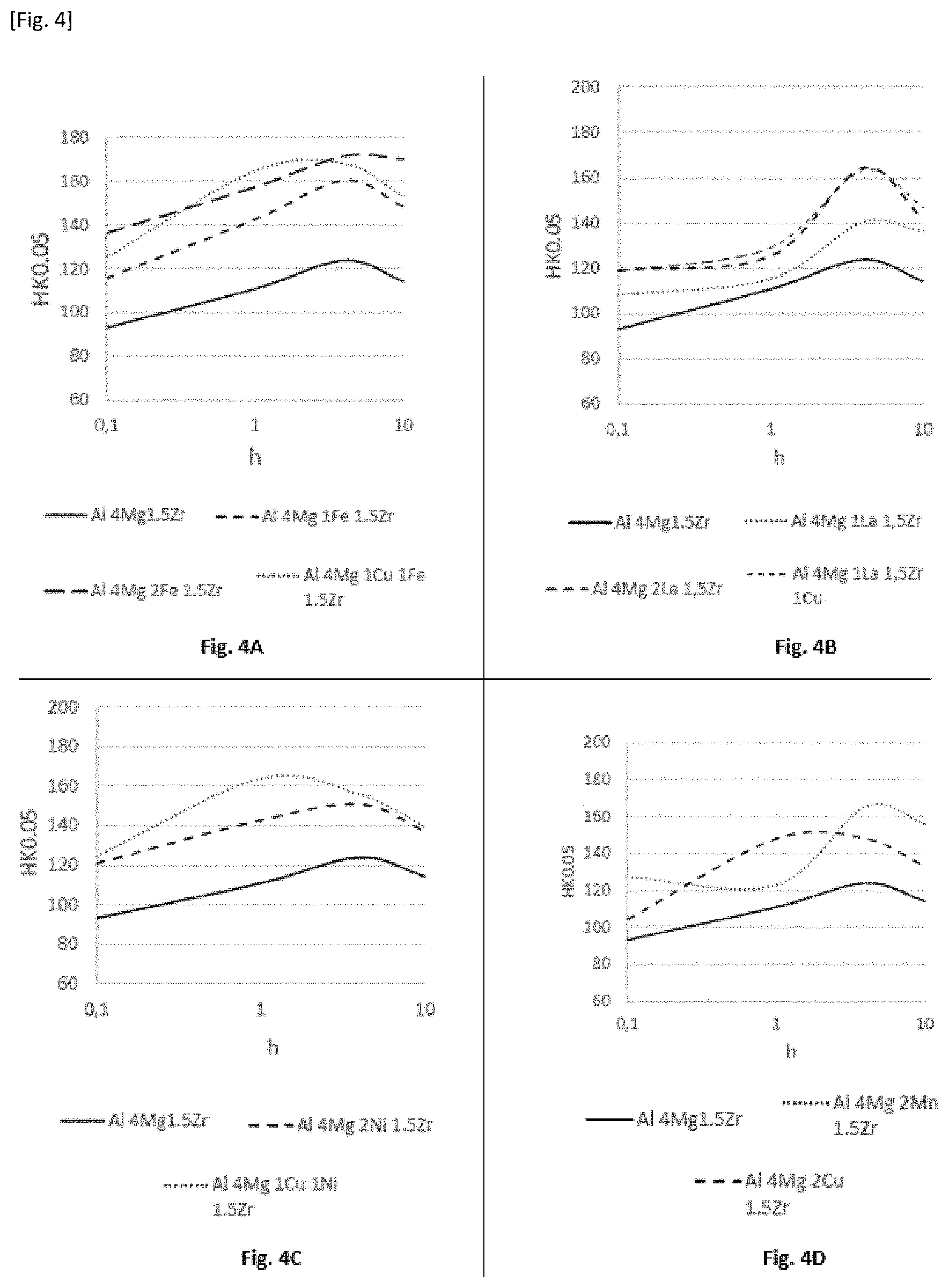
[0051] FIGS. 4A to 4D illustrate Knoop hardness values (ordinate axis) of samples made using compositions according to the invention as a function of a duration of a heat post-treatment at 400.degree. C. (abscissa axis).
[0052] FIGS. 5A to 5F show a section of a sample of a reference alloy having been exposed to a laser beam according to different scan speeds, the power of the laser being respectively 250 W, 300 W, 350 W, 400 W, 450 W and 500 W.
[0053] FIGS. 6A to 6F show a section of a sample according to the present invention of an alloy Al-4% Mg-1.5% Zr-2% Cu having been exposed to a laser beam according to different scan speeds, the power of the laser being respectively 250 W, 300 W, 350 W, 400 W, 450 W and 500 W.
[0054] FIGS. 7A to 7F show a section of a sample according to the present invention of an alloy Al-4% Mg-1.5% Zr-2% Ni having been exposed to a laser beam according to different scan speeds, the power of the laser being respectively 250 W, 300 W, 350 W, 400 W, 450 W and 500 W.
[0055] FIGS. 8A to 8F show a section of a sample according to the present invention of an alloy Al-4% Mg-1.5% Zr-2% Fe having been exposed to a laser beam according to different scan speeds, the power of the laser being respectively 250 W, 300 W, 350 W, 400 W, 450 W and 500 W.
[0056] FIGS. 9A to 9F show a section of a sample according to the present invention of an alloy Al-4% Mg-1.5% Zr-2% Mn having been exposed to a laser beam according to different scan speeds, the power of the laser being respectively 250 W, 300 W, 350 W, 400 W, 450 W and 500 W.
[0057] FIGS. 10A to 10F show a section of a sample according to the present invention of an alloy Al-4% Mg-1.5% Zr-2% La having been exposed to a laser beam according to different scan speeds, the power of the laser being respectively 250 W, 300 W, 350 W, 400 W, 450 W and 500 W.
[0058] FIG. 11 is a diagram representing a Wire Arc Additive Manufacturing method, commonly referred to by the acronym WAAM.
[0059] FIG. 12 is a diagram of the specimen used according to the examples.
DISCLOSURE OF PARTICULAR EMBODIMENTS
[0060] Unless stated otherwise, in the description: [0061] the designation of the aluminum alloys is compliant with the nomenclature of The Aluminum Association; [0062] the contents of the chemical elements are reported in % and represent weight fractions. The x %-y % notation means higher than or equal to x % and lower than or equal to y %.
[0063] FIG. 1 represents a SLM-type additive manufacturing device, mentioned in connection with the prior art. The device uses an aluminum alloy, forming a filler material, and provided in the form of a powder 15, lying on a support 10. An energy source, in this instance a laser source 11, emits a laser beam 12. The laser source is coupled to the filler material by an optical system 13, whose movement is determined according to a digital model M. The laser beam 12 follows a movement according to the longitudinal plane XY, describing a pattern depending on the digital model. The movement is performed according to a scan speed, which represents the speed of displacement of the beam relative to the powder. The interaction of the laser beam 12 with the powder 15 causes a selective melting of the latter, followed by a solidification, resulting in the formation of a layer 20.sub.1 . . . 20.sub.n. Once a layer has been formed, it is covered with powder 15 and another layer is formed, superimposed on the layer made before. For example, the thickness of the powder forming a layer may be from 10 to 200 .mu.m.
[0064] For aluminum alloys, the support 10 or tray may be heated up to a temperature ranging up to 350.degree. C. In general, machines that are currently available on the market enable heating of the tray up to 200.degree. C. For example, the heating temperature of the tray may be about 50.degree. C., 100.degree. C., 150.degree. C. or 200.degree. C. In general, heating of the tray allows reducing the humidity at the powder bed and also reducing the residual stresses on the parts being manufactured. The humidity level at the powder bed seems to have a direct effect on the porosity of the final part. Indeed, it seems that the higher the humidity of the powder, the higher will be the porosity of the final part. It should be noted that heating of the tray is one of the existing possibilities to carry out a hot additive manufacturing. However, the present invention should not be limited to the use of this heating means alone. All other heating means may be used in the context of the present invention to heat up and monitor the temperature, for example an infrared lamp. Thus, the method according to the present invention may be carried out at a temperature ranging up to 350.degree. C.
[0065] The powder may have at least one of the following characteristics: [0066] average particle size from 5 to 100 .mu.m, preferably from 5 to 25 .mu.m, or from 20 to 60 .mu.m. The given values mean that at least 80% of the particles have an average size within the specified range. [0067] spherical shape. For example, the sphericity of a powder may be determined using a morphogranulometer. [0068] good castability. For example, the castability of a powder may be determined according to the standard ASTM B213 or the standard ISO 4490:2018. According to the standard ISO 4490:2018, the flow time is preferably shorter than 50 s. [0069] low porosity, preferably from 0 to 5%, more preferably from 0 to 2%, still more preferably from 0 to 1% by volume. In particular, the porosity may be determined by optical microscopy or scanning electron microscope or by helium pycnometry (cf. the standard ASTM B923). [0070] absence or small amount (less than 10%, preferably less than 5% by volume) of small particles (1 to 20% of the average size of the powder), called satellites, which stick to the larger particles.
[0071] The inventors have looked for an alloy composition, forming the filler material, allowing obtaining acceptable mechanical properties without requiring the application of heat treatments, subsequent to the formation of the layers, that is to say after the formation of the final part, which might induce a distortion. In particular, these consist of heat treatments involving an abrupt variation of the temperature. Thus, the invention allows obtaining, by additive manufacturing, a part whose mechanical properties are satisfactory, in particular in terms of hardness. Depending on the selected additive manufacturing method type, the filler material may be in the form of a powder, as described before. In this case, the exposure of the powder (15) to a beam of light (12) or of charged particles results in a local melting followed by a solidification, so as to form a solid layer (20.sub.1 . . . 20.sub.n).
[0072] According to one variant, the filler metal may also be in the form of a wire, as described in connection with FIG. 11. In this case, the exposure of the filler wire (35) to a heat source (32) results in a local melting followed by a solidification, so as to form a solid layer (20.sub.1 . . . 20.sub.n).
[0073] The inventors have noticed that a part having satisfactory mechanical properties could be obtained using an aluminum alloy combining: [0074] a magnesium content from 0 to 6% and preferably from 1 to 6%, and preferably from 3 to 4.5%. A magnesium content lower than 3.5% may also be advantageous, in particular for corrosion resistance after thermal exposure. [0075] a zirconium content according to a first variant from 1 to 2.5%, and preferably from 1 to 2%, while being strictly higher than 1%. A Zr content from 1.2 to 2% or from 1.2 to 1.8% is considered to be optimum. Or according to a second variant from 0.7 to 2%; and possibly from 0.7 to 1.6%; and possibly from 0.7 to 1.4%; and possibly from 0.8 to 1.4%; and possibly from 0.8 to 1.2%. [0076] an alloy element, whose content is higher than 0.1%, or higher than 0.25% or 0.5%, the alloy element being selected amongst Fe, Cu, Ni, Mn and/or La. Preferably, the content of each alloy element is lower than 5%, more preferably lower than 3%. Preferably, the cumulative content of each alloy element is from 0.1 to 5%. It may be lower than 10%.
[0077] The use of such an alloy in an additive manufacturing method is accompanied with the following advantages: [0078] a good compatibility with additive manufacturing methods, in particular the SLM method: this is reflected by the absence of cracks at the layers formed successively; [0079] a good corrosion resistance, in particular when the magnesium content is from 3 to 4.5%, or when the latter is lower than 3.5%. [0080] a melting (liquidus) point lower than 1050.degree. C., and preferably lower than 1000.degree. C., which limits the evaporation of Mg during the fusion. When the Mg content is 4%, the liquidus temperature is lower than 1050.degree. C. when the Zr content is lower than 2.2%. When the Zr content is lower than 1.6%, the liquidus temperature is lower than 1000.degree. C. With such an alloy, a part featuring a high hardness is obtained. For these reasons, a Zr content from 0.7 to 2% or from 1 to 2% or from 1.2 to 1.8%, is optimum when the Mg content is in the range of 4% and preferably in the presence of Mn.
[0081] FIG. 2 represents an evolution of the liquidus temperature as a function of the Zr content, for an aluminum alloy including 4% of Mg. This curve has been obtained using the FactSage 7.1 software using the VLAB database. It shows that a Zr content lower than 2.2% allows keeping the liquidus temperature lower than or equal to 1050.degree. C. Moreover, a Zr content lower than or equal to 0.7%, and possibly 1% is considered to be non-advantageous, the mechanical properties then being insufficient, for example a maximum hardness lower than 120 HK0.05. A Zr content close to 1.5%, that is to say from 1 to 2%, or from 1.2 to 2% or from 1.2 to 1.8%, seems to be optimum, according to a first variant, preferably in the presence of Mn.
[0082] The alloy may include other alloy elements, selected from: Si, Hf, V, Cr, Ta, Nb, W, Ti, Y, Yb, Ce, Co, Mo, Nd and/or Er, the content of the other alloy element or of each other alloy element being from 0.05 to 5%, or from 0.1 to 3%, or from 0.1 to 2%, or from 0.1 to 1%, or from 0.1 to 0.5%. The weight fraction of the other alloy elements, considered as a whole, is preferably lower than 10%, and preferably lower than 5%, and preferably lower than 3% and even 2%. Such elements may generate an increase in the hardness by a solid solution effect and/or by the formation of dispersoids or fine intermetallic phases.
[0083] The alloy may include other elements selected amongst Sr, Ba, Sb, Bi, Ca, P, B, In, Sn, according to a weight fraction lower than or equal to 1%, and preferably lower than or equal to 0.1%, and still preferably lower than or equal to 700 ppm for each element. Preferably, the total weight fraction of these elements is lower than 2%, and preferably lower than 1%. It may be preferable to avoid an excessive addition of Bi, the preferred weight fraction being lower than 0.05%, and preferably lower than 0.01%.
[0084] The alloy may include other elements such as: [0085] Ag, according to a weight fraction from 0.06 to 1%; [0086] and/or Li, according to a weight fraction from 0.06 to 2%; [0087] and/or Zn, according to a weight fraction from 0.05 to 5%, preferably from 0.1 to 3%.
[0088] According to one embodiment, the alloy may also comprise at least one element for refining the grains and avoiding a coarse columnar microstructure, for example AITiC or AlTiB.sub.2, for example a refining agent in the ATSB or AT3B form, according to an amount smaller than or equal to 50 kg/ton, and preferably smaller than or equal to 20 kg/ton, still more preferably equal 12 kg/ton for each element, and smaller than or equal to 50 kg/ton, and preferably smaller than or equal to 20 kg/ton for all these elements.
[0089] Subsequently to the formation of the layers, that is to say subsequently to the formation of the final part, the method may include a heat treatment, referred to by the term post-treatment. It may include a dissolution followed by quenching and tempering. However, as previously described, quenching may cause a deformation of the part formed by additive manufacturing, in particular, when the dimensions of the latter are large. Henceforth, when a heat treatment is applied, it is preferable that its temperature is from 300 to 600.degree. C., preferably lower than 500.degree. C. or more preferably lower than or equal to 450.degree. C., and for example from 100.degree. C. to 450.degree. C. In particular, it may consist of hardening tempering or annealing. In general, the heat treatment may enable a relief of the residual stresses and/or an additional precipitation of hardening phases.
[0090] Preferably, the method according to the present invention does not include any quenching-type heat treatment following the formation of the layers, that is to say following the formation of the final part.
[0091] According to one embodiment, the method may include a hot isostatic pressing (HIP). In particular, the HIP treatment may allow improving the elongation properties and the fatigue properties. The hot isostatic pressing may be carried out before, after or instead of the heat treatment. Advantageously, the hot isostatic pressing is carried out at a temperature from 250.degree. C. to 550.degree. C. and preferably from 300.degree. C. to 450.degree. C., at a pressure from 500 to 3000 bars and over a duration from 0.5 to 10 hours. Depending on the pursued properties, the temperature of the HIP treatment will not exceed 450.degree. C., and possibly 400.degree. C., because the increase of the temperature reduces the mechanical strengths.
[0092] In particular, the possible heat treatment and/or the hot isostatic pressing allows increasing the hardness of the obtained product, under some conditions, in particular temperature conditions.
[0093] According to another embodiment, suited to alloys with structural hardening, it is possible to carry out a dissolution followed by quenching and tempering of the formed part and/or a hot isostatic pressing. In this case, the hot isostatic pressing may advantageously replace the dissolution.
[0094] However, the method according to the invention is advantageous, because it preferably does not require any dissolution treatment followed by quenching. The dissolution may have a detrimental effect on the mechanical strength in some cases by participating in an enlargement of dispersoids or fine intermetallic phases.
[0095] According to one embodiment, the method according to the present invention further includes, optionally, a machining treatment, and/or a chemical, electrochemical or mechanical surface treatment, and/or a vibratory finishing. In particular, these treatments may be carried out to reduce the roughness and/or improve the corrosion resistance and/or improve the resistance to fatigue cracking.
[0096] Optionally, it is possible to carry out a mechanical deformation of the part, for example after the additive manufacture and/or before the heat treatment.
[0097] The tests described in the following description show that the use of the alloy according to the invention allows obtaining parts having a high hardness. This allows avoiding resort to post-manufacture heat treatments involving an abrupt variation of temperature, and which might induce a distortion, as mentioned before.
[0098] The inventors have also noticed that the alloy as previously described is particularly suited to be applied in an additive manufacturing method, during which the alloy undergoes a local melting followed by a solidification. In particular, the alloy is suited to a method combining high power and high scan speed. Thus, the alloy is suitable for an efficient implementation of an additive manufacturing method.
EXAMPLES
[0099] Tests 1.
[0100] The tested alloys have been cast in a copper mold using an Induthem VC 650V machine to obtain ingots with a 130 mm height, a 95 mm width and a 5 mm thickness.
[0101] The alloys as described in Table 1 hereinbefore have been tested by a rapid prototyping method. Samples have been machined for scanning of the surface with a laser, in form of strips having 60.times.22.times.3 mm dimensions, from the ingots obtained hereinbefore. The strips have been placed in a SLM machine and scans of the surface have been performed with a laser following the same scanning strategy and process conditions representative of those used for the SLM process. Indeed, it has been noticed that, in this manner, it was possible to assess the capability of the alloys of the SLM method and in particular the surface quality, the sensitivity to hot cracking, the hardness at the raw state and the hardness after heat treatment.
[0102] Under the laser beam, the metal melts in a bath having a 10 to 350 .mu.m thickness. After passage of the laser, the metal rapidly cools down as in the SLM method. After laser scanning, a fine surface layer having a 10 to 350 .mu.m thickness has molten and then solidified. The properties of the metal in this layer are close to the properties of the metal at the core of a part manufactured by SLM, because the scanning parameters are properly selected. Laser scanning of the surface of the different samples has been performed using a selective laser melting machine ProX300 of the trademark 3DSystems. The laser source had a 250 W power, the scattering vector was 60 .mu.m, the scan speed was 300 mm/s and the diameter of the beam was 80 .mu.m.
[0103] Knoop Hardness Measurement
[0104] Hardness is a major property for alloys. Indeed, if the hardness of the layer re-melted by scanning of the surface with a laser is high, a part manufactured with the same alloy would probably have a high tensile strength.
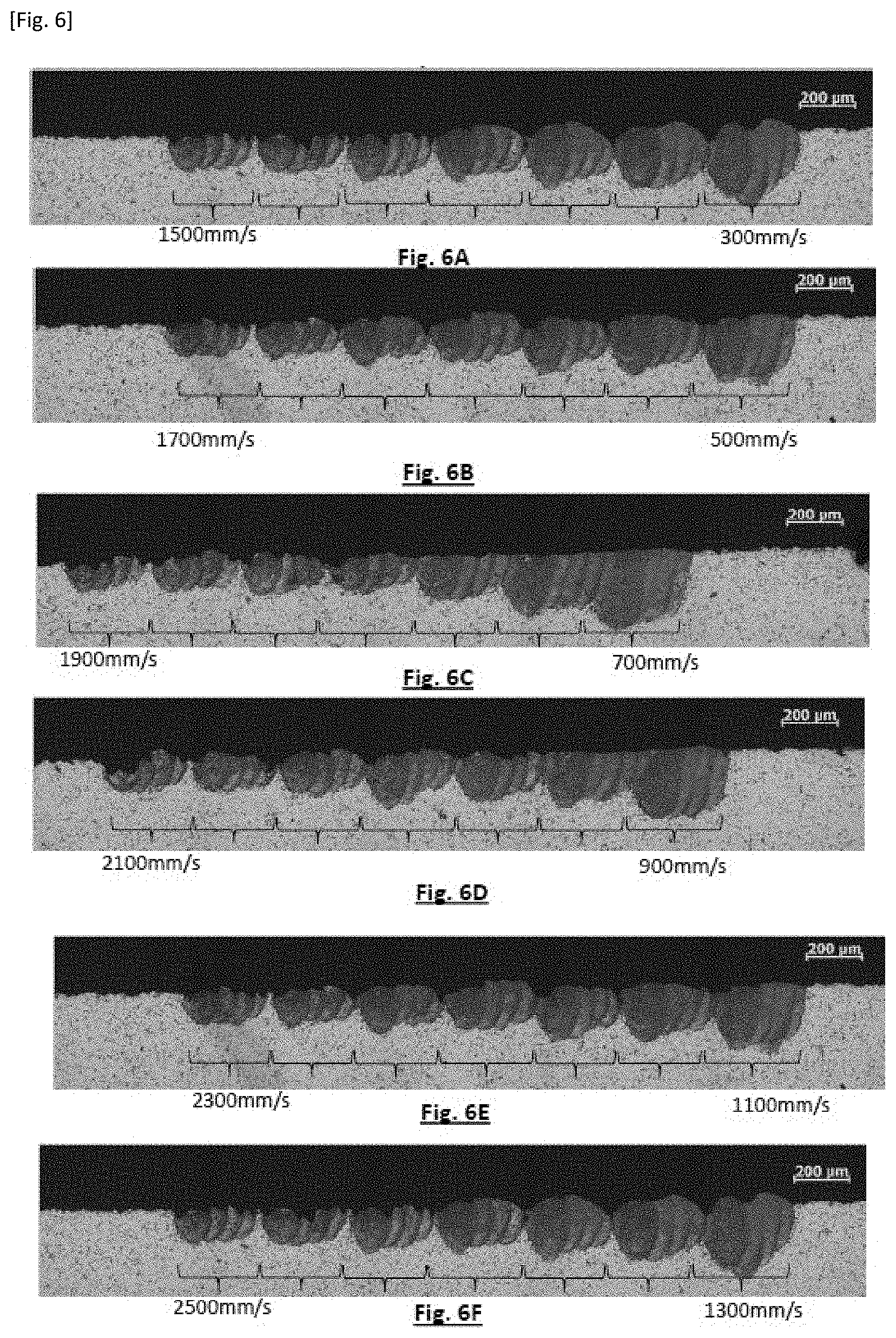
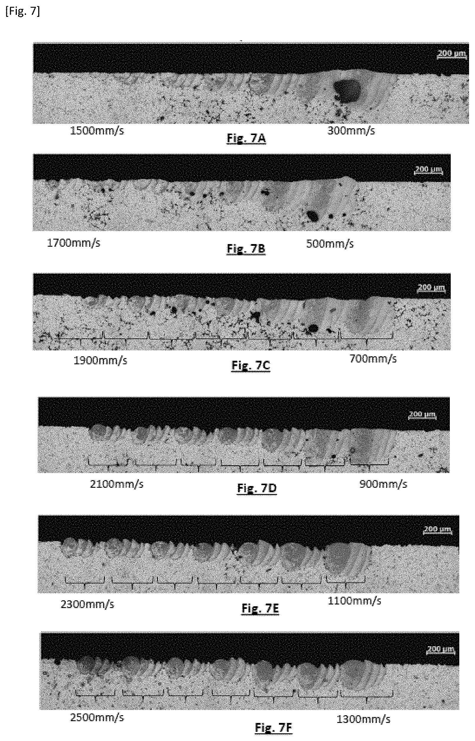
[0105] To assess the hardness of the re-melted layer, the strips obtained hereinbefore have been cut in the plane perpendicular to the direction of the passes of the laser and have been polished afterwards. After polishing, hardness measurements have been performed in the re-melted layer. The hardness measurement has been performed with a Durascan model apparatus from Struers. The 50 g Knoop hardness method with the large diagonal of the indent placed parallel to the plane of the re-melted layer has been selected to keep enough distance between the indent and the edge of the sample. 15 indents have been positioned at mid-thickness of the re-melted layer. FIG. 3 shows an example of the hardness measurement. The reference numeral 1 corresponds to the re-melted layer and the reference numeral 2 corresponds to a Knoop hardness indent.
[0106] The hardness has been measured according to Knoop's scale with a 50 g load after laser treatment (in the raw state) and after an additional heat treatment at 400.degree. C. over variable durations, allowing assessing in particular the ability of the alloy to be hardened during a heat treatment and the effect of a possible CIC treatment on the mechanical properties.
[0107] Following each test, a heat post-treatment has been applied on some samples. The heat treatment consists of a hardening annealing, at a temperature of 400.degree. C., and that being so during 1 hour, or 4 hours, or 10 hours.
[0108] A reference alloy including aluminum, as well as the following alloy elements, has been used: Mg (4%); Zr (1.5%). The reference alloy is as described in the publication WO2018/185259. The composition of the tested aluminum alloys is reported in Table 1 hereinafter, in weight percents:
TABLE-US-00001 TABLE 1 Com- position No. Mg Zr Cu Fe Mn Ni La Ref 4% 1.5% 1 4% 1.5% 2% 2 4% 1.5% 1% 3 4% 1.5% 2% 4 4% 1.5% 1% 1% 5 4% 1.5% 2% 6 4% 1.5% 2% 7 4% 1.5% 1% 1% 8 4% 1.5% 1% 9 4% 1.5% 2% 10 4% 1.5% 1% 1%
[0109] Table 2 hereinafter shows the Knoop 0.05 hardness values measured for each alloy, namely after laser treatment, in a raw state (column 0h), after hardening annealing at 400.degree. C., carried out after the laser treatment, for 1 hour (column 1h), or over 4 hours (column 4h), or over 10 hours (column 10h). The max column indicates the maximum hardness level measured on the different tested samples. The values in bold indicate the heat treatment having led to the highest hardness value.
TABLE-US-00002 TABLE 2 Com- position No. liquidus 0 h 1 h 4 h 10 h max Ref 990 93 111 124 114 124 1 995 104 148 148 133 148 2 993 116 143 160 148 160 3 996 136 157 171 170 171 4 995 125 165 168 153 168 5 987 121 143 151 137 151 6 995 127 123 165 156 165 7 991 125 164 156 139 164 8 994 108 115 140 136 140 9 998 119 125 164 142 164 10 996 119 129 163 147 163
[0110] FIG. 4A shows the obtained results relating to the compositions 2 (1% Fe), 3 (2% Fe) and 4 (1% Fe, 1% Cu), as well as with the reference composition. Notice that the compositions 2, 3 and 4 allow obtaining a hardness higher than the reference composition, irrespective of the duration of the heat treatment. The highest hardness values are obtained with a heat treatment duration of 4h. The highest values are obtained with the compositions 3 (2% Fe) and 4 (1% Fe-1% Cu).
[0111] FIG. 4B shows the obtained results relating to the compositions 8 (1% La), 9 (2% La) and 10 (1% La, 1% Cu), as well as with the reference composition. Notice that the compositions 8, 9 and 10 allow obtaining a hardness higher than the reference composition, irrespective of the duration of the heat treatment. The highest hardness values are obtained with a heat treatment duration of 4h. The highest values are obtained with the compositions 9 (2% La) and 10 (1% La-1% Cu).
[0112] FIG. 4C shows the obtained results relating to the compositions 5 (2% Ni), 7 (1% Cu, 1% Ni) as well as with the reference composition. Notice that the compositions 5 and 7 allow obtaining a hardness higher than the reference composition, irrespective of the duration of the heat treatment. The highest hardness values are obtained with a heat treatment duration of 4 hours for the composition 7 and 1 hour for the composition 5. The highest values are obtained with the composition 7 (1% Cu-1% Ni).
[0113] FIG. 4D shows the obtained results relating to the compositions 1 (2% Cu), 6 (2% Mn) as well as with the reference composition. Notice that the compositions 1 and 6 allow obtaining a hardness higher than the reference composition, irrespective of the duration of the heat treatment. The highest values are obtained with the composition 6 (2% Mn).
[0114] These results show that: [0115] Resorting to at least one alloy element, selected from Fe, Cu, Ni, Mn, La, with a content higher than or equal to 0.1% individually, allows increasing hardness in comparison with the reference composition, devoid of these alloy elements; [0116] The application of a hardening annealing, in particular at a temperature of 400.degree. C., improves hardness, the optimum duration being obtained by implementing a heat treatment according to a duration from 1h to 8h, for example equal to 4h. [0117] The compositions 3 (2% Fe), 4 (1% Cu-1% Fe), 6 (2% Mn), 7 (1% Cu, 1% Ni), 9 (2% La) and 10 (1% La-1% Cu) lead to the highest hardness values. [0118] The compositions featuring Fe and/or Cu, with a cumulated content of 2%, seem to be particularly suitable.
[0119] Tests 2
[0120] Samples have been machined in form of strips having 60.times.22.times.3 mm dimensions, from the ingots obtained hereinbefore (cf. Tests 1). During a second series of tests, these samples have undergone a scanning using a laser beam, according to different powers (between 250 W and 500 W) and different speeds (between 300 mm/s and 2500 mm/s). The size of the laser beam was 80 .mu.m. The speed range has been adapted to the power. Thus: [0121] at a power of 250 W, the speed has varied between 300 mm/s and 1500 mm/s, by 200 mm/s increments; [0122] at a power of 300 W, the speed has varied between 500 mm/s and 1700 mm/s, by 200 mm/s increments; [0123] at a power of 350 W, the speed has varied between 700 mm/s and 1900 mm/s, by 200 mm/s increments; [0124] at a power of 400 W, the speed has varied between 900 mm/s and 2100 mm/s, by 200 mm/s increments; [0125] at a power of 450 W, the speed has varied between 1100 mm/s and 2300 mm/s, by 200 mm/s increments; [0126] at a power of 500 W, the speed has varied between 1300 mm/s and 2500 mm/s, by 200 mm/s increments.
[0127] The objective of these tests was to analyze the morphology of the superficial portion of each sample after the melting and solidification phases. The superficial portion having undergone these phase changes is referred to by the term "molten area". It is considered as representative of the morphology of the layers formed by additive manufacturing. The tests have allowed characterizing the surface condition of the samples, in particular porosity and roughness. Each sample has undergone a section across the thickness thereof, the latter having been characterized using an optical microscope. The results of the characterizations, for different compositions, are represented in FIGS. 5A to 5F, 6A to 6F, 7A to 7F, 8A to 8F, 9A to 9F, 10A to 10F. Each figure corresponds to a section carried out at constant power, while making the scan speed vary between a minimum speed, indicated to the left of the figure, and a maximum speed, indicated to the right of the figure. Thus, each figure shows the profiles of the surface exposed to the laser beam for different speeds, at the same power. At each power level, 7 speeds, with 4 lines per speed, have been tested. The portions of the samples corresponding to the same scan speed have been represented with a brace. In the figures, it is observed that the lines corresponding to the same speed (i.e. within the same brace) partially overlap.
[0128] FIGS. 5A, 5B, 5C, 5D, 5E and 5F show the sections obtained with samples whose composition corresponds to the reference composition described in Table 1, respectively for the powers 250 W, 300 W, 350 W, 400 W, 450 W, 500 W.
[0129] FIGS. 6A, 6B, 6C, 6D, 6E and 6F show the sections obtained with samples whose composition corresponds to the composition No. 1 described in Table 1 (4% Mg; 1.5% Zr-2% Cu), respectively for the powers 250 W, 300 W, 350 W, 400 W, 450 W, 500 W.
[0130] FIGS. 7A, 7B, 7C, 7D, 7E and 7F show the sections obtained with samples whose composition corresponds to the composition No. 5 described in Table 1 (4% Mg; 1.5% Zr-2% Ni), respectively for the powers 250 W, 300 W, 350 W, 400 W, 450 W, 500 W.
[0131] FIGS. 8A, 8B, 8C, 8D, 8E and 8F show the sections obtained with samples whose composition corresponds to the composition No. 3 described in Table 1 (4% Mg; 1.5% Zr-2% Fe), respectively for the powers 250 W, 300 W, 350 W, 400 W, 450 W, 500 W.
[0132] FIGS. 9A, 9B, 9C, 9D, 9E and 9F show the sections obtained with samples whose composition corresponds to the composition No. 6 described in Table 1 (4% Mg; 1.5% Zr-2% Mn), respectively for the powers 250 W, 300 W, 350 W, 400 W, 450 W, 500 W.
[0133] FIGS. 10A, 10B, 10C, 10D, 10E and 10F show the sections obtained with samples whose composition corresponds to the composition No. 9 described in Table 1 (4% Mg; 1.5% Zr-2% La), respectively for the powers 250 W, 300 W, 350 W, 400 W, 450 W, 500 W.
[0134] The compositions having undergone the tests reported in FIGS. 6 to 10 correspond to those resulting in most favorable hardness values throughout the first series of tests. It is observed that these compositions allow obtaining a smoother and less porous surface condition, than the reference composition. Hence, they are best suited to be implemented in an additive manufacturing method. In addition, these compositions allow obtaining satisfactory surface conditions at high speed and high power. They are particularly suited to an implementation of an additive manufacturing method with high build rates.
[0135] Tests 3
[0136] Test parts have been made by SLM, using an alloy 11, whose weight composition measured by ICP included: Al; Zr 1.64%; Fe 2.12%; Mg 2.56%; impurities: <0.05% each with cumulated impurities <0.15%.
[0137] These tests have been carried out using a E0S290 SLM (supplier EOS) type machine.
[0138] This machine enables a heating of the tray up to a temperature of 200.degree. C. The tests have been carried out at a heating temperature of 200.degree. C. but complementary tests have demonstrated the good processability of the alloys according to the present invention at lower heating temperatures, for example 25.degree. C., 50.degree. C., 100.degree. C. or 150.degree. C.
[0139] The power of the laser was 370 W. The scan speed was equal to 1250 mm/s. The deviation between two adjacent scan lines, usually referred to by the term "scattering vector" was 0.111 mm. The layer thickness was 60 .mu.m.
[0140] The used powder had a particle size essentially comprised from 3 .mu.m to 100 .mu.m, with a median of 38 .mu.m, a 10% fractile of 14 .mu.m and a 90% fractile of 78 .mu.m.
[0141] The test parts have been made, in the form of solid cylinders vertical (direction Z) with respect to the construction tray which forms the base thereof in the plane (X-Y). The cylinders have a diameter of 11 mm and a height of 46 mm. All parts have been subjected to a SLM post-manufacture relaxation treatment of 4 hours at 300.degree. C.
[0142] Some parts have been subjected to a post-manufacture heat treatment at 400.degree. C. for a treatment duration comprised between 1 h to 4 h. All parts (with and without the post-manufacture heat treatment) have been machined to obtain cylindrical tensile specimens having the following characteristics in mm (cf. Table 3 and FIG. 12):
[0143] In FIG. 12 an Table 3, 0 represents the diameter of the central portion of the specimen, M the width of the two ends of the specimen, LT the total length of the specimen, R the radius of curvature between the central portion and the ends of the specimen, Lc the length of the central portion of the specimen and F the length of the two ends of the specimen.
TABLE-US-00003 TABLE 3 Type .0. M LT R Lc F TOR 4 4 8 45 3 22 8.7
[0144] These cylindrical specimens have been tested in tension at room temperature in the direction of manufacture Z according to the standard NF EN ISO 6892-1 (2009-10).
[0145] Table 4 hereinafter summarizes the tensile properties (yield strength, tensile strength and elongation at break) as a function of the conditions of the post-manufacture heat treatment (duration, temperature).
TABLE-US-00004 TABLE 4 Duration Temperature Rp0.2 Rm A (h) (.degree. C.) (MPa) (MPa) (%) 0 -- 303 369 15.6 1 400 455 457 6.1 4 400 474 475 5.2
[0146] Tests 4
[0147] A fourth test similar to the test 3 has been carried out using the alloy 4 whose weight composition measured by ICP included Al; Zr 1.3%; Mn 4.47%; Mg 2.53%; impurities: <0.05% each with cumulated impurities <0.15%.
[0148] The used powder had a particle size essentially comprised from 3 .mu.m to 100 .mu.m, with a median of 40 .mu.m, a 10% fractile of 14 .mu.m and a 90% fractile of 84 .mu.m.
[0149] Table 5 hereinafter summarizes the tensile properties (yield strength, tensile strength and elongation at break) as a function of the conditions of the post-manufacture heat treatment (duration, temperature).
TABLE-US-00005 TABLE 5 Duration Temperature Rp0.2 Rm A (h) (.degree. C.) (MPa) (MPa) (%) 0 -- 372 445 6.9 1 400 424 488 3.8 4 400 435.5 500 3.75
[0150] Tests 5
[0151] A fifth test similar to the tests 3 and 4 has been carried out using the alloy 5 whose weight composition measured by ICP included Al; Zr 1.13%; Mn 4.45%; Mg 1.09%; impurities: <0.05% each with cumulated impurities <0.15%.
[0152] The used powder had a particle size essentially comprised from 3 .mu.m to 100 .mu.m, with a median of 25 .mu.m, a 10% fractile of 9.6 .mu.m and a 90% fractile of 52 .mu.m.
TABLE-US-00006 TABLE 6 Duration Temperature Rp0.2 Rm A (h) (.degree. C.) (MPa) (MPa) (%) 0 -- 314.5 376 11.6 1 400 393 440 5.7 4 400 391 442 5.1
[0153] Although described in connection with a SLM-type additive manufacturing method, which corresponds to the preferred method, the previously-described compositions may be used in other types of tests.
[0154] FIG. 11 represents a WAAM-type additive manufacturing device, mentioned in connection with the prior art. An energy source 31, in this instance a torch, forms an electric arc 32. In this device, the torch 31 is held by a welding robot 33. The part to be manufactured is disposed on a support 10. In this example, the manufactured part is a wall extending according to a transverse axis Z perpendicular to a longitudinal plane XY defined by the support 10. Under the effect of the electric arc 32, the filler wire 35 melts so as to form a welding bead. The welding robot is controlled by a digital model M. The filler wire is moved so as to form different layers 20.sub.1 . . . 20.sub.n, stacked on one another, forming the wall 20, each layer corresponding to a welding bead. Each layer 20.sub.1 . . . 20.sub.n extends in the longitudinal plane XY, according to a pattern defined by the digital model M.
[0155] Preferably, the diameter of the filler wire is smaller than 3 mm. It may be from 0.5 mm to 3 mm and is preferably from 0.5 mm to 2 mm, and possibly from 1 mm to 2 mm. For example, it is 1.2 mm.
[0156] Moreover, other manufacturing methods may be considered, for example, and without limitation: [0157] Selective Laser Sintering (or SLS); [0158] Direct Metal Laser Sintering (or DMLS); [0159] Selective Heat Sintering (or SHS); [0160] Electron Beam Melting (or EBM); [0161] Direct Energy Deposition (or DED); [0162] Direct Metal Deposition (or DMD); [0163] Direct Laser Deposition (or DLD); [0164] Laser Deposition Technology; [0165] Laser Engineering Net Shaping; [0166] Laser Cladding Technology; [0167] Laser Freeform Manufacturing Technology (or LFMT); [0168] Laser Metal Deposition (or LMD); [0169] Cold Spray Consolidation (or CSC); [0170] Additive Friction Stir (or AFS); [0171] Field Assisted Sintering Technology (FAST) or spark plasma sintering; [0172] Inertia Rotary Friction Welding (or IRFW).
* * * * *
D00000
D00001
D00002
D00003
D00004
D00005
D00006
D00007
D00008
D00009
D00010
XML
uspto.report is an independent third-party trademark research tool that is not affiliated, endorsed, or sponsored by the United States Patent and Trademark Office (USPTO) or any other governmental organization. The information provided by uspto.report is based on publicly available data at the time of writing and is intended for informational purposes only.
While we strive to provide accurate and up-to-date information, we do not guarantee the accuracy, completeness, reliability, or suitability of the information displayed on this site. The use of this site is at your own risk. Any reliance you place on such information is therefore strictly at your own risk.
All official trademark data, including owner information, should be verified by visiting the official USPTO website at www.uspto.gov. This site is not intended to replace professional legal advice and should not be used as a substitute for consulting with a legal professional who is knowledgeable about trademark law.