Large-caliber, Hoop-free And Well-sealed Plastic Barrel
LI; Aoqi ; et al.
U.S. patent application number 17/561800 was filed with the patent office on 2022-04-21 for large-caliber, hoop-free and well-sealed plastic barrel. The applicant listed for this patent is Ningbo Changqi Fluorine Plastic Products Co., Ltd.. Invention is credited to Aoqi LI, Hongwei LI.
| Application Number | 20220119167 17/561800 |
| Document ID | / |
| Family ID | |
| Filed Date | 2022-04-21 |


| United States Patent Application | 20220119167 |
| Kind Code | A1 |
| LI; Aoqi ; et al. | April 21, 2022 |
LARGE-CALIBER, HOOP-FREE AND WELL-SEALED PLASTIC BARREL
Abstract
A large-caliber, hoop-free and well-sealed plastic barrel, including a barrel body with a rim portion and a cover. The rim portion is provided with a sealing ring, whose outer peripheral surface is a first sealing surface. An outer side of the barrel body is provided with an annular clamp ring, which is arranged below the sealing ring. The cover is provided with a sealing groove fitting the rim portion. An outer surface of an inner side wall of the sealing groove tightly fit an inner wall of the rim portion. An inner surface of an outer side wall of the sealing groove is provided with a second sealing surface in a seal fit with the first sealing surface. An outer peripheral surface of the cover is provided with a hook strip, whose inner side wall is provided with a flange to be clamped with the clamp ring.
| Inventors: | LI; Aoqi; (Ningbo, CN) ; LI; Hongwei; (Ningbo, CN) | ||||||||||
| Applicant: |
|
||||||||||
|---|---|---|---|---|---|---|---|---|---|---|---|
| Appl. No.: | 17/561800 | ||||||||||
| Filed: | December 24, 2021 |
| International Class: | B65D 43/02 20060101 B65D043/02; B65D 1/16 20060101 B65D001/16 |
Foreign Application Data
| Date | Code | Application Number |
|---|---|---|
| Jun 4, 2021 | CN | 202110623715.2 |
Claims
1. A hoop-free plastic barrel, comprising: a barrel body with a rim portion; and a cover configured for sealing the rim portion; wherein a side edge of the rim portion of the barrel body is provided with a sealing ring; an outer peripheral surface of the sealing ring is a first sealing surface; an outer side of the barrel body is provided with an annular clamp ring; the annular clamp ring is arranged below the sealing ring; the cover is provided with a sealing groove configured for fitting the rim portion; the sealing groove comprises an inner side wall and an outer side wall; wherein the inner side wall of the sealing groove is close to a center of the barrel body, and the outer side wall of the sealing groove is away from the center of the barrel body; pan outer side surface of the inner side wall of the sealing groove tightly fit an inner wall of the rim portion; an inner side surface of the outer side wall of the sealing groove is provided with a second sealing surface in a seal fit with the first sealing surface; an outer peripheral surface of the cover is provided with a hook strip corresponding to the annular clamp ring; and an inner side wall of the hook strip is provided with a flange configured to be clamped with the annular clamp ring.
2. The hoop-free plastic barrel of claim 1, wherein the hook strip is connected to a lower end of the outer side wall of the sealing groove; and an inner side of a connection between the hook strip and the outer side wall of the sealing groove is provided with a tearing groove.
3. The hoop-free plastic barrel of claim 2, wherein the cover is provided with a cover opening wrench; the hook strip is annularly arranged below the outer side wall of the sealing groove; a head end of the hook strip and a tail end of the hook strip are arranged at two sides of the cover opening wrench, respectively; and the head end of the hook strip is provided with a pull strip configured to facilitate tearing away the hook strip.
4. The hoop-free plastic barrel of claim 3, wherein a connection between the cover opening wrench and the outer side wall of the sealing groove is provided with the tearing groove.
5. The hoop-free plastic barrel of claim 3, wherein the outer side of the barrel body is provided with an annular retaining ring; and a lower end of the cover opening wrench extends to an upper end surface of the annular retaining ring.
6. The hoop-free plastic barrel of claim 1, wherein the outer peripheral surface of the sealing ring is vertically provided with the first sealing surface; the inner side surface of the outer side wall of the sealing groove is provided with a protrusion ring; and the protrusion ring is provided with the second sealing surface in a seal fit with the first sealing surface.
7. The hoop-free plastic barrel of claim 6, wherein a thickness of an upper edge of the rim portion is larger than a distance between the first sealing surface and the second sealing surface.
8. The hoop-free plastic barrel of claim 7, wherein the thickness of the upper edge of the rim portion is 0.1-1 mm larger than the distance between the first sealing surface and the second sealing surface.
9. The hoop-free plastic barrel of claim 6, wherein a lower end surface of the protrusion ring is provided with an inclined surface configured to facilitate an installation of the barrel body.
Description
CROSS-REFERENCE TO RELATED APPLICATIONS
[0001] This application claims the benefit of priority from Chinese Patent Application No. 202110623715.2, filed on Jun. 4, 2021. The content of the aforementioned application, including any intervening amendments thereto, is incorporated herein by reference in its entirety.
TECHNICAL FIELD
[0002] This application relates to sealing of large-caliber plastic barrels, and more particularly to a large-caliber, hoop-free and well-sealed plastic barrel.
BACKGROUND
[0003] Nowadays, high-grade powdered or liquid chemical raw materials (i.e., polytetrafluoroethylene (PTFE)) with moisture-proof and sealing requirements are generally stored in plastic barrels with a hoop. The hoop is used to fix and tighten the barrel lid, so as to improve the sealing performance of the barrel lid. However, such sealing method fails to arrive at the desirable sealing of the plastic barrels. A liner or a nylon bag may be arranged in the barrel for secondary packaging. Specifically, since the ordinary large-caliber plastic barrels have poor sealing performance, the items are primarily packaged by the liner or nylon bag, and then subjected to secondary packaging with the plastic barrel, so as to improve the sealing performance and prevent leakage.
[0004] However, the manufacture process of the hoop-equipped plastic barrel requires a procedure of fastening the hoop, which specifically includes hooping, clamping, and rotational locking of the hoop. Moreover, this operation can only be manually carried out. Therefore, the production of such plastic barrel is time-consuming and labor-intensive, and the locking may be unreliable. In addition, it is difficult to achieve the fully-automated batch production and packaging due to the complicated process. Regarding the secondary packaging method, the arrangement of the liner or nylon bag greatly increases the production cost, and is also not suitable for the large-scale automated production and packaging. Therefore, it is needed to design a large-caliber, hoop-free and well-sealed plastic barrel, which has simple structure, and is suitable for the mass automated packaging.
SUMMARY
[0005] An objective of the present disclosure is to provide a large-caliber, hoop-free and well-sealed plastic barrel, which has a simple structure and good sealing performance, and is suitable for the automated mass production and packaging.
[0006] The technical solutions of the present disclosure are described as follows.
[0007] This application provides a hoop-free plastic barrel, comprising:
[0008] a barrel body with a rim portion; and
[0009] a cover configured for sealing the rim portion;
[0010] wherein a side edge of the rim portion of the barrel body is provided with a sealing ring; an outer peripheral surface of the sealing ring is a first sealing surface; an outer side of the barrel body is provided with an annular clamp ring; the annular clamp ring is arranged below the sealing ring; the cover is provided with a sealing groove configured for fitting the rim portion; the sealing groove comprises an inner side wall and an outer side wall; wherein the inner side wall of the sealing groove is close to a center of the barrel body, and the outer side wall of the sealing groove is away from the center of the barrel body; an outer side surface of the inner side wall of the sealing groove tightly fit with an inner wall of the rim portion; an inner side surface of the outer side wall of the sealing groove is provided with a second sealing surface in a seal fit with the first sealing surface; an outer peripheral surface of the cover is provided with a hook strip corresponding to the annular clamp ring; and an inner side wall of the hook strip is provided with a flange configured to be clamped with the annular clamp ring.
[0011] In some embodiments, the hook strip is connected to a lower end of the outer side wall of the sealing groove; an inner side of a connection between the hook strip and the outer side wall of the sealing groove is provided with a tearing groove. The tearing groove largely facilitates a disassembly of the cover after an installation.
[0012] In some embodiments, the cover is provided with a cover opening wrench; the hook strip is annularly arranged below the outer side wall of the sealing groove; a head end of the hook strip and a tail end of the hook strip are arranged at two sides of the cover opening wrench, respectively; and the head end of the hook strip is provided with a pull strip configured to facilitate tearing away the hook strip. The annularly arranged hook strip ensures the fixing reliability of the cover, and the pull strip and the tearing groove help to tear the hook strip, which facilitates the disassembly of the cover.
[0013] In some embodiments, a connection between the cover opening wrench and the outer side wall of the sealing groove is provided with the tearing groove. The tearing groove helps to lift up and open the cover opening wrench.
[0014] In some embodiments, an outer side of the barrel body is provided with the annular retaining ring; and a lower end of the cover opening wrench extends to an upper end surface of the annular retaining ring, effectively avoiding the cover opening wrench being opened accidently and improving the reliability of the barrel body.
[0015] In some embodiments, the outer peripheral surface of the sealing ring is vertically provided with the first sealing surface; the inner side surface of the outer side wall of the sealing groove is provided with a protrusion ring; and the protrusion ring is provided with the second sealing surface in a seal fit with the first sealing surface.
[0016] In some embodiments, a thickness of an upper edge of the rim portion is larger than a distance between the first sealing surface and the second sealing surface. The rim portion and the sealing groove are in an interference fit, which effectively improves the sealing performance of the barrel body.
[0017] In some embodiments, the thickness of the upper edge of the rim portion is 0.1-1 mm larger the distance between the first sealing surface and the second sealing surface. When the difference is within such interval, the rim portion of the barrel body can be installed to a deeper position inside the sealing groove, providing a better sealing performance and fixing reliability, and facilitating the installation of the cover.
[0018] In some embodiments, a lower end surface of the protrusion ring is provided with an inclined surface configured to facilitate an installation of the barrel body. The inclined surface help to guide and position during the installation of the rim portion, which facilitates the positioning and packaging of the equipment during the automated production, reducing the requirements on the accuracy of the equipment, and improving the fault tolerance rate of the equipment.
[0019] The beneficial effects of the present disclosure are described as follows.
[0020] In the plastic barrel, the sealing groove is in seal fit with the rim portion, which allows the reliable sealing of the barrel body. Specifically, the first sealing surface provided on the sealing ring tightly fit the second sealing surface on the inner side surface of the outer side wall of the sealing groove. The lower end surface of the protrusion ring is provided with the inclined surface to guide the installation of the barrel body, and thus the rim portion of the barrel body can be easily installed in the sealing groove, facilitating the automatic production. In addition, the clamp ring arranged on the outer side of the barrel body is clamped with the corresponding hook strip to fix the cover and avoid an axial movement of the cover after the installation, so as to further ensure the sealing reliability of the barrel body. Therefore, the sealing and fixing of the barrel body and the cover can be completed by one-step pressing, which is simple and easy to operate, such that the mass automatic sealing packaging and production may be easily reached, improving the production efficiency, reducing the labor intensity and shortening the production cycle. The tearing groove facilitates the operator to tear the hook strip along the tearing groove, such that the cover has simple disassembly.
BRIEF DESCRIPTION OF THE DRAWINGS
[0021] FIG. 1 schematically depicts a cross-sectional structure of a barrel body according to an embodiment of the present disclosure;
[0022] FIG. 2 is an enlarged view of part A in FIG. 1;
[0023] FIG. 3 schematically depicts a structure of a cover according to an embodiment of the present disclosure;
[0024] FIG. 4 is a cross-sectional view of the structure of the cover in FIG. 3;
[0025] FIG. 5 is an enlarged view of part B in FIG. 4;
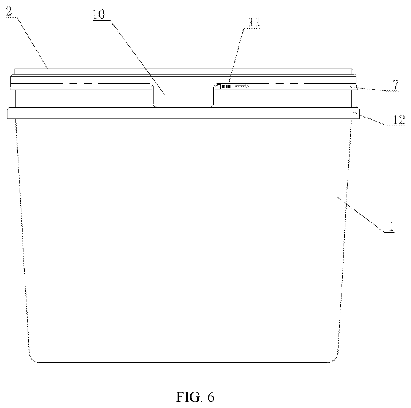
[0026] FIG. 6 schematically depicts the barrel body after the cover is installed according to an embodiment of the present disclosure;
[0027] FIG. 7 schematically depicts a cross-sectional view of the barrel body in FIG. 6;
[0028] FIG. 8 is an enlarged view of part C in FIG. 7; and
[0029] FIG. 9 schematically depicts the plastic barrel according to an embodiment of the present disclosure after a hook strip is torn.
DETAILED DESCRIPTION OF EMBODIMENTS
[0030] The present disclosure will be further described in detail below with reference to the embodiments and the accompany drawings.
[0031] Referring to an embodiment shown in FIGS. 1-9, a large-caliber, hoop-free and well-sealed plastic barrel is provided, which includes a barrel body 1 providing with a rim portion 3 and a cover 2 configured for sealing the rim portion 3. An outer edge of the rim portion 3 of the barrel 1 is integrally provided with a sealing ring 4. An outer peripheral surface of the sealing ring 4 is vertically provided with a first sealing surface 4.1. The cover 2 is provided with a sealing groove 5 configured for fitting the rim portion 3. The sealing groove 5 includes an inner side wall 5.1 and an outer side wall 5.2. The inner side wall 5.1 of the sealing groove 5 is close to a center of the barrel body 1, and the outer side wall 5.2 of the sealing groove 5 is away from the center of the barrel body 1. An outer side surface of the inner side wall 5.1 of the sealing groove 5 tightly fit with an inner wall of the rim portion 3. An inner side surface of the outer side wall 5.2 of the sealing groove 5 is provided with a protrusion ring 5.3. The protrusion ring 5.3 is provided with a second sealing surface 5.4 that is in a seal fit with the first sealing surface 4.1. A lower end surface of the protrusion ring 5.3 is provided with an inclined surface 5.5 configured to allow the barrel body 1 to be conveniently installed.
[0032] An outer side of the barrel body 1 is provided with an annular clamp ring 6. The annular clamp ring 6 is arranged below the sealing ring 4. An outer peripheral surface of the cover 2 is provided with a hook strip 7 corresponding to the annular clamp ring 6. The cover 2 is also provided with a cover opening wrench 10. The hook strip 7 is annularly arranged below the outer side wall 5.2 of the sealing groove 5. A head end of the hook strip 7 and a tail end of the hook strip 7 are arranged at two sides of the cover opening wrench 10, respectively. The head end of the hook strip 7 is provided with a pull strip 11 configured to conveniently tear the hook strip 7. An inner side wall of the hook strip 7 is provided with a flange 9 fixedly clamping with the annular clamp ring 6. The hook strip 7 is connected to a lower end of the outer side wall 5.2 of the sealing groove 5. A tearing groove 8 is provided on an inner side of a connection between the hook strip 7 and the outer side wall 5.2 of the sealing groove 5. An outer side of the barrel body 1 is provided with an annular retaining ring 12. A lower end of the cover opening wrench 10 extends to an upper end surface of the annular retaining ring 12.
[0033] A connection between the cover opening wrench 10 and the outer side wall 5.2 of the sealing groove 5 may be provided with the tearing groove 8. The tearing groove 8 on the cover opening wrench 10 is aligned with the tearing groove 8 on the hook strip 7. The tearing groove 8 allows an operator to conveniently tear off the cover opening wrench 10, and then allows the operator to conveniently tear the hook strip 7 along the tearing groove 8 through the pull strip 11. The tearing groove 8 has a thickness of 0.3-0.6 mm, and a width of 0.5-0.6 mm.
[0034] A thickness of an upper edge of the rim portion 3 is larger than a distance between the first sealing surface 4.1 and the second sealing surface 5.4. A difference between the thickness of the upper edge of the rim portion 3 and the distance between the first sealing surface 4.1 and the second sealing surface 5.4 is 0.1-1 mm; preferably 0.5 mm.
[0035] Raw material of the barrel body 1 and the cover 2 is made of polypropylene (PP), polyethylene (PE) or a modified engineering plastic of PE. A shrinkage rate of a product obtained through injection molding of the raw material is less than 1.5% to ensure the sealing performance of the product.
[0036] A process of using the large-caliber, hoop-free and well-sealed plastic barrel is described as follows. The cover 2 is pressed on an upper end of the barrel body 1, that is, the rim portion 3 of the barrel body 1 is installed in the sealing groove 5. Due to the inclined surface 5.5 arranged on the lower end surface of the protrusion ring 5.3, the rim portion of the barrel body can be easily installed in the sealing groove 1. The inclined surface 5.5 plays a guiding role and facilitates the automated production. Since the thickness of the upper edge of the rim portion 3 is greater than the distance between the first sealing surface 4.1 and the second sealing surface 5.4, the outer side surface of the inner side wall 5.1 of the sealing groove 5 and the inner wall of the rim portion 3 are in a sealing and tight fit. The second sealing surface 5.4 provided on the protrusion ring 5.3 closely fits with the first sealing surface 4.1 on the sealing ring 4 to achieve an interference fit. In other words, a seal fit between the cover 2 and the edge 3 of the barrel body 1 is achieved through the plasticity of the cover 2, and the sealing reliability of the barrel body 1 is improved through double-sided sealing. In this process, the annular clamp ring 6 arranged on the outer side surface of the barrel body 1 is clamped with the hook strip 7. Specifically, the clamp ring 6 is clamped with the flange 9 arranged on the hook strip 7 to fix the cover 2 and avoid an axial movement of the cover 2 after the installation, so as to further ensure the sealing reliability for the barrel body 1. When the cover 2 needs to be disassembled, the hook strip 7 is torn along the tearing groove 8 through the pull strip 11, that is, the clamp ring is separated from the flange 9 to release a clamping state, and the operator can lift up the cover 2 at this time.
[0037] The above-mentioned embodiments are merely preferred embodiments of this disclosure, and are not intended to limit the present disclosure. It should be understood that variations and modifications made by those skilled in the art without departing from the spirit of this disclosure should fall within the scope of the present disclosure defined by the appended claims.
* * * * *
D00000
D00001
D00002
D00003
D00004
D00005
D00006
D00007
XML
uspto.report is an independent third-party trademark research tool that is not affiliated, endorsed, or sponsored by the United States Patent and Trademark Office (USPTO) or any other governmental organization. The information provided by uspto.report is based on publicly available data at the time of writing and is intended for informational purposes only.
While we strive to provide accurate and up-to-date information, we do not guarantee the accuracy, completeness, reliability, or suitability of the information displayed on this site. The use of this site is at your own risk. Any reliance you place on such information is therefore strictly at your own risk.
All official trademark data, including owner information, should be verified by visiting the official USPTO website at www.uspto.gov. This site is not intended to replace professional legal advice and should not be used as a substitute for consulting with a legal professional who is knowledgeable about trademark law.