Locking System, In Particular For A Motor Vehicle
BECHER; Andreas
U.S. patent application number 17/293106 was filed with the patent office on 2022-04-21 for locking system, in particular for a motor vehicle. The applicant listed for this patent is MARQUARDT GMBH. Invention is credited to Andreas BECHER.
| Application Number | 20220118943 17/293106 |
| Document ID | / |
| Family ID | |
| Filed Date | 2022-04-21 |


| United States Patent Application | 20220118943 |
| Kind Code | A1 |
| BECHER; Andreas | April 21, 2022 |
LOCKING SYSTEM, IN PARTICULAR FOR A MOTOR VEHICLE
Abstract
The invention relates to a locking system (3), in particular for providing authorization to access and/or drive of a motor vehicle (1) in the manner of a keyless entry/go functionality. The locking system (3) comprises a first device (4), having at least two states and being configured as a control system, such as a control system for releasing and/or locking the car doors (6), the ignition lock, the steering wheel lock, for releasing and/or blocking the immobilizer, the motor control device or the like, and an associated second device (5) in the form of an electronic key, an ID transmitter, a chip card or the like. Both devices (4, 5) comprise for the operation thereof transmission and/or receiving units for the transmission of in particular electromagnetic signals (7), wherein the transmission and/or receiving unit has an antenna for transmitting the signals (7). At least one of the signals (7) transmitted between the second device (5) and the first device (4) is a coded operating signal for authenticating said second device (5) in such a way that once the transmitted operating signal has been positively identified for the authorized second device (5), the state of the first device (4) can be modified. The transmission and/or receiving unit (10) for the first device (4) comprises two antennae (11, 12). Furthermore, a signal distributor (13) in the form of a power splitter is provided for both antennae (11, 12). The transmission and/or receiving unit (10) is in communication with both antennae (11, 12) via the signal distributor (13).
| Inventors: | BECHER; Andreas; (Villingen-Schwenningen, DE) | ||||||||||
| Applicant: |
|
||||||||||
|---|---|---|---|---|---|---|---|---|---|---|---|
| Appl. No.: | 17/293106 | ||||||||||
| Filed: | July 9, 2020 | ||||||||||
| PCT Filed: | July 9, 2020 | ||||||||||
| PCT NO: | PCT/EP2020/069365 | ||||||||||
| 371 Date: | May 12, 2021 |
| International Class: | B60R 25/24 20060101 B60R025/24; G07C 9/00 20060101 G07C009/00 |
Foreign Application Data
| Date | Code | Application Number |
|---|---|---|
| Aug 21, 2019 | DE | 10 2019 005 815.1 |
Claims
1. A locking system, in particular for providing authorization to access and/or drive a motor vehicle (1) in the manner of a keyless entry/go functionality, comprising a first device (4) which has at least two states and is designed as a control system, such as a control system for unlocking and/or locking the car doors (6), the ignition lock, the steering wheel lock, for releasing and/or blocking the immobilizer, the engine control device or the like, and an associated second device (5) designed in the manner of an electronic key, an ID transmitter, a chip card or the like, wherein the two devices (4, 5), for their intended operation, comprise transmission and/or receiving units for the transmission of, in particular, electromagnetic signals (7), wherein in particular at least one of the signals (7) transmitted between the second device (5) and the first device (4) is a coded operating signal for authentication of the second device (5), so that after positive evaluation of the transmitted operating signal, a change in the state of the first device (4) can be effected in the case of an authorized second device (5), and wherein the transmission and/or receiving unit has an antenna for transmitting the signals (7), characterized in that the transmission and/or receiving unit (10) for the first device (4) comprises two antennas (11, 12), that a signal distributor (13) in the form of a power splitter is provided for the two antennas (11, 12), and that the transmission and/or receiving unit (10) is in communication with the two antennas (11, 12) by means of the signal distributor (13). cm 2. The locking system according to claim 1, characterized in that the two antennas (11, 12) are arranged spatially separated, and that preferably the one antenna (11) is associated with the interior area (9) as an indoor antenna and the other antenna (12) is associated with the exterior area (8) as an outdoor antenna.
3. The locking system according to claim 1 or 2, characterized in that the signal distributor (13) operates the two antennas (11, 12) with different power in the manner of an asymmetrical signal distributor, in particular that the signal distributor (13) operates the indoor antenna (11) with about 10% and the outdoor antenna (12) with about 90% of the total power.
4. The locking system according to claim 1, 2 or 3, characterized in that the signal distributor (13) has an input (17) for the signal transmission (14) between the transmission and/or receiving unit (10) and the signal distributor (13) and in each case one output (18, 19) between the signal distributor (13) and the respective antenna (12, 11), and that preferably the signal strength for the output (18) to the outdoor antenna (12) is almost lossless, in particular that the decoupling at the output (18) to the outdoor antenna (12) is set with a loss of about 0.5 dB, and that further preferably the signal strength for the output (19) to the indoor antenna (11) is set to be lossy, in particular that the decoupling at the output (19) to the indoor antenna (11) is set with a loss of about 10 dB.
5. The locking system according to any one of claims 1 to 4, characterized in that the signal strength for the outdoor antenna (12) is set by means of a loose coupling between the input (17) of the asymmetrical signal distributor (13) and the output (19) of the asymmetrical signal distributor (13) to the indoor antenna (11).
6. The locking system according to any one of claims 1 to 5, characterized in that the transmission of the signals (7) takes place by means of a carrier in the RF (radio frequency) range, and that the RF range is preferably Bluetooth, in particular Bluetooth Low Energy (BLE) with a frequency of about 2.45 GHz.
7. The locking system according to any one of claims 1 to 6, characterized in that the second device is a smartphone (5'), in particular with a BLE (Bluetooth Low Energy) interface.
Description
[0001] The invention is based on a locking system according to the preamble of patent claim 1.
[0002] In the case of increased security requirements, electronic locking systems are used which operate, for example, by means of electromagnetic waves. In particular in molar vehicles, such locking systems are used as door locking systems for access authorization, and/or as ignition lock systems, steering wheel locks, immobilizers or the like for driving authorization.
[0003] Such locking systems are known from DE 43 40 260 A1. The locking system consists of a first device having at least two states and being designed as a control system for unlocking and/or locking the car doors, the ignition lock or the like, and an associated second device designed in the form of an electronic key. For their intended operation, the two devices comprise transmission and/or receiving units for transmitting the signals, in particular electromagnetic signals, wherein the transmission and/or receiving unit have an antenna for transmitting the signals. In the intended operation, at least one signal can be transmitted between the key and the control system as a coded operating signal for authenticating the key, so that after positive evaluation of the transmitted operating signal and thus when the key is authorized, a change in the state of the control system can be effected.
[0004] Such locking systems are also refined with so-called "keyless" functionalities. With "Keyless Entry" functionality, for example, manual operation of the electronic key by the user is no longer necessary. It is sufficient for the user to carry the key with him. The operating signal for access authorization is then automatically transmitted between the two devices when the user is in an operating area in the vicinity of the motor vehicle and operates the door handle on the car door, for example. Likewise, these locking systems can have a "KeylessGo" functionality, wherein the operating signal for driving authorization is automatically transmitted between the two devices when the user is inside the motor vehicle and, for example, presses a start/stop button in the dashboard.
[0005] In order to ensure optimum transmission of the signals both in the interior and exterior of the motor vehicle, a transmission and/or receiving unit with an antenna for the interior area and for the exterior area is provided in each case in the first device. The disadvantage of such a locking system therefore appears to be in particular the production cost thereof.
[0006] The underlying object of the invention is to further develop the locking system in such a manner that it is more cost-effective with substantially the same functionality.
[0007] This object is achieved in a generic locking system by the characterizing features of claim 1.
[0008] In the locking system according to the invention, only a single transmission and/or receiving unit is provided for the first device, wherein the transmission and/or receiving unit for the first device comprises two antennas. Furthermore, a signal distributor in the form of a power splitter is provided for the two antennas. The transmission and/or receiving unit is in communication with the two antennas by means of the signal distributor. Due to the fact that only the one single transmission and/or receiving unit is needed for both antennas, a substantial reduction of costs is therefore achieved. Further configurations of the invention are the subject matter of the sub-claims.
[0009] For the purpose of good transmission of the signals in the respective area, the two antennas can be arranged spatially separated. In fact, one antenna can preferably be associated with the interior as an indoor antenna and the other antenna can be associated with the exterior as an outdoor antenna. In this way, good signal coverage can be achieved for the entire vehicle.
[0010] Furthermore, the signal distributor can operate the two antennas with different power in the manner of an asymmetrical signal distributor for the purpose of adaptation to the respective areas. In particular, it may be suitable for the signal distributor to operate the indoor antenna at about 10% and the outdoor antenna at about 90% of the total power for the transmission power. The invention thus provides the further knowledge that the indoor antenna requires less power than the outdoor antenna, since a smaller area is to be covered by the indoor antenna.
[0011] In a further configuration, the signal distributor can have an input for signal transmission between the transmission and/or receiving unit and the signal distributor and an output between the signal distributor and the respective antenna. In this case, the signal strength for the output to the outdoor antenna can preferably be selected with almost no loss. In particular, the decoupling at the output to the outdoor antenna can be set with a loss of about 0.5 dB (decibels). Furthermore, the signal strength for the output to the indoor antenna can be selected to be lossy in this case. In particular, the decoupling at the output to the indoor antenna can be set with a loss of about 10 dB. Furthermore, the signal strength for the outdoor antenna can be set by means of a loose coupling between the input of the asymmetrical signal distributor and the output of the asymmetrical signal distributor to the indoor antenna.
[0012] Finally, the transmission of the signals can be performed by means of a carrier in the RF (radio frequency) range. In particular, it can be suitable for the RF range to be the standardized Bluetooth, in particular Bluetooth Low Energy (BLE) with a carrier frequency of about 2.45 GHz. Furthermore, the second device can be a smartphone on which a corresponding application program is installed, in particular one with a BLE (Bluetooth Low Energy) interface, which is already available to most users. In this respect, the costs conventionally incurred for an electronic key as a second device can then be saved.
[0013] For a particularly preferred configuration of the invention, the following is to be noted.
[0014] The use of smartphones as vehicle keys is making its way into the first vehicles, in particular electric vehicles, such as Tesla vehicles. For reasons of comfort, it is desirable that the smartphone does not have to be operated by the user if possible, but rather has keyless functionality. A wireless interface at dose range is particularly suitable for this comfort application. The smartphone offers a Bluetooth Low Energy interface for this, which operates at about 2.45 GHz. A disadvantage of this interface is the slightly higher frequency, which results in difficulties in signal coverage in the interior and/or exterior area. Solutions with one antenna are also opposed by the increased use of thermal insulation glazing which strongly attenuates high-frequency signals. However, the use of two spatially separated antennas also requires the use of two Bluetooth Low Energy transmission and/or receiving units for optimum signal coverage, which in turn leads to higher costs.
[0015] The invention provides that signal coverage for interior and/or exterior areas is implemented with two antennas and only one Bluetooth Low Energy transmission and/or receiving unit. In this case, the signal from the Bluetooth Low Energy transmission and/or receiving unit is distributed to the two antennas via an asymmetrical RF signal distributor. In the invention, the following knowledge is gained. If this were done with a simple symmetrical "power splitter", both antennas would lose half of the signal strength, which in turn would lead to a severe reduction in signal propagation. The reduced signal propagation would lead to a significantly reduced radio range, in particular in the exterior area. In contrast, the reduced radio range in the vehicle interior would have little effect on signal coverage because in the vehicle interior, the distances between the indoor antenna and the smartphone are considerably shorter. If an asymmetrical RF signal distributor is now used, loose coupling between the input of the asymmetrical RF signal distributor and the output to the indoor antenna can be used to adjust the signal strength for the outdoor antenna such that it is virtually lossless while still providing good indoor signal coverage for the indoor antenna with acceptable losses. In particular, it appears to be a good compromise to select an output of the indoor antenna with a loss of 10 dB, which in turn leads to a loss of 0.5 dB for the outdoor antenna.
[0016] Created by means of the invention is an asymmetrical RF signal distributor for signal coverage in the interior and/or exterior area of a vehicle for a smart access system. The invention can be used for all applications in which signal coverage is necessary in a body of a vehicle or in a room as well as in the exterior area of the body or room, wherein in particular the interior area should always be smaller than the exterior area.
[0017] The advantages achieved with the invention are, in particular, that the solution according to the invention saves costs for an additional transmission and/or receiving unit, which may be a Bluetooth Low Energy transmission and/or receiving unit. In addition, the invention makes it easier to maintain the Bluetooth Low Energy connection of the vehicle with the smartphone since the smartphone maintains this connection when the smartphone changes position from the interior area to the exterior area. In a solution with two Bluetooth Low Energy transmission and/or receiving units, this connection to the respective Bluetooth Low Energy transmission and/or receiving unit must always be re-established. This can result in malfunctions and/or signal delays, which is advantageously avoided in the invention.
[0018] Exemplary embodiments of the invention with various refinements and configurations are shown in the drawings and are described in more detail below. In the figures:
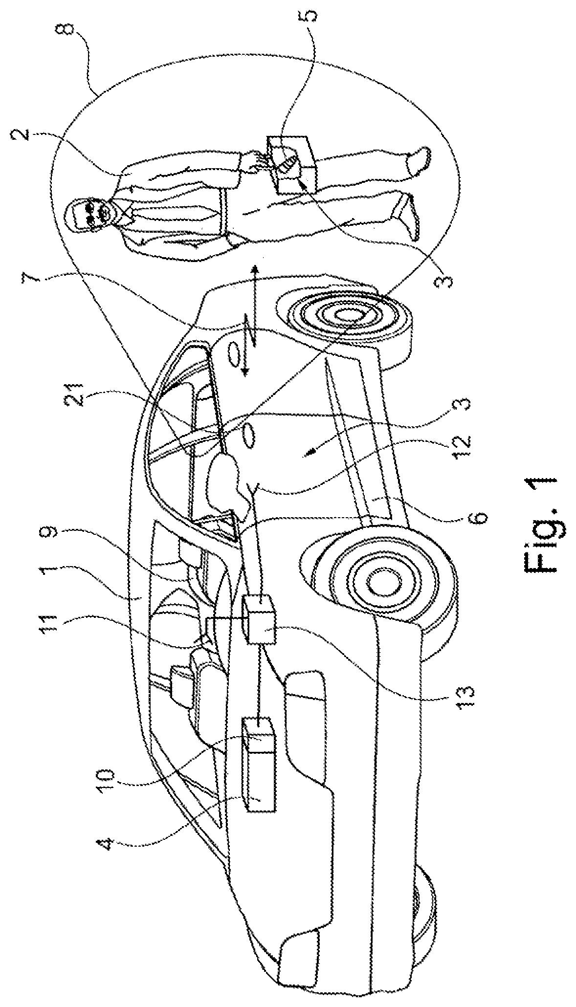
[0019] FIG. 1 shows a motor vehicle equipped with a locking system,
[0020] FIG. 2 shows a locking system according to a further embodiment in schematic form, comprising a smartphone, wherein the smartphone is located in the exterior area of the motor vehicle, and
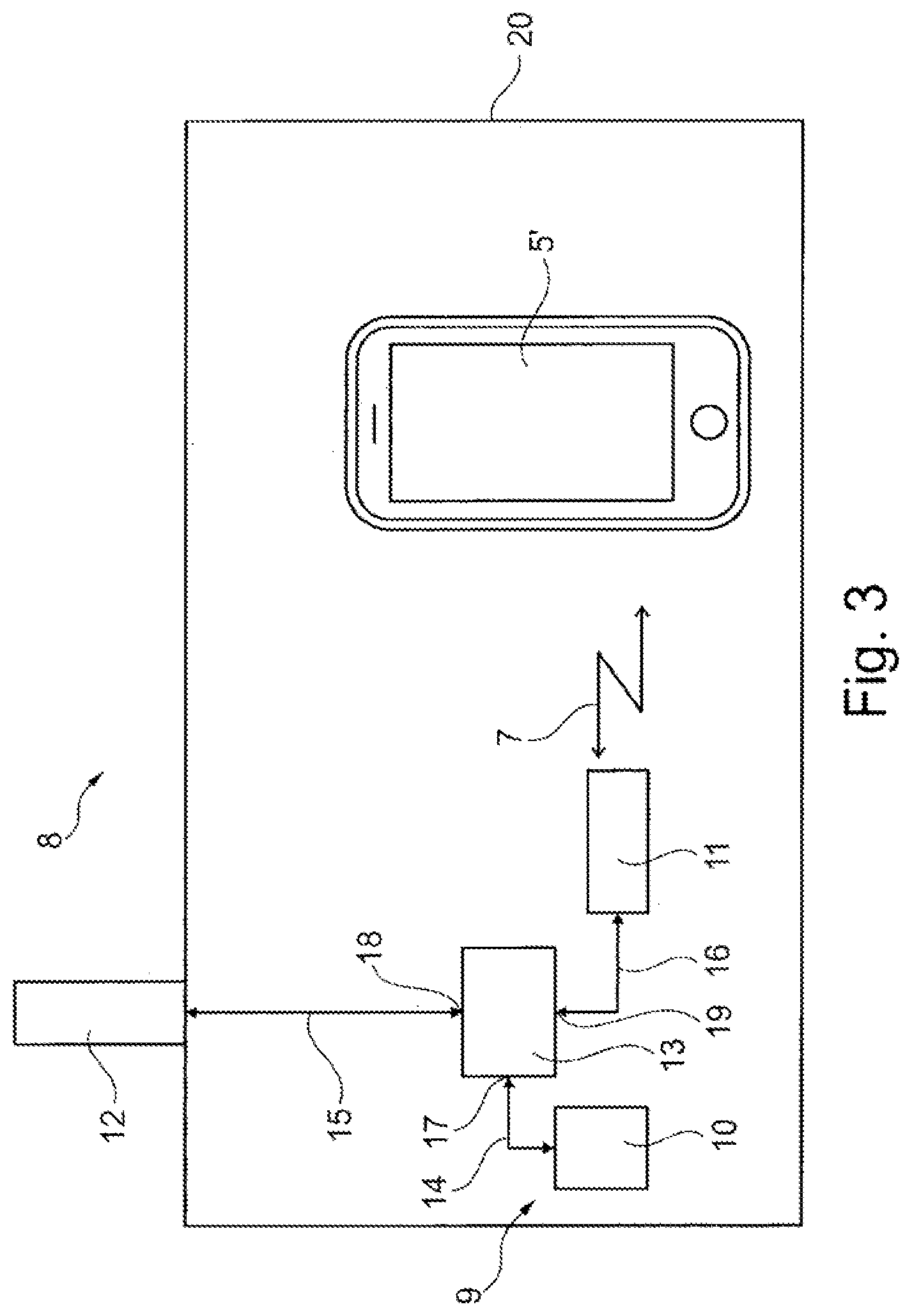
[0021] FIG. 3 shows the locking system of FIG. 2, wherein the smartphone is located in the interior area of the motor vehicle.
[0022] In FIG. 1, a motor vehicle 1 with the authorized user 2 is shown. For access authorization, the motor vehicle 1 is provided with a locking system 3 as a door locking system, which comprises a first device 4 designed as a control system and an associated second device 5. The second device 5 is designed in the form of an electronic key, an identification (ID) transmitter, a chip card, a smart card or the like. The second device 5 is in the possession of the authorized user 2, whereby the latter has access to the molar vehicle 1 in the exterior area 8, and more precisely within an operating area 8, of the motor vehicle 1.
[0023] The first device 4 has at least two slates, wherein in the first stale, a locking is implemented and in the second state, an unlocking of the car doors 6 is implemented. For their intended operation, the two devices 4, 5 comprise transmission and/or receiving units with an antenna for the transmission of electromagnetic signals 7 by means of an electromagnetic carrier wave. At least one of these signals 7 transmitted between the second device 5 and the first device 4 is a coded, electromagnetic operating signal. The coded operating signal is used to authenticate the second device 5, so that after positive evaluation of the transmitted operating signal, a change in the state of the first device 4 can be effected in the case of an authorized second device 5. The transmission of coded operating signal takes place when the authorized user 2 operates the door handle 21 on the car door 6 or approaches the door handle 21. As a result, the unlocking of the car doors 6 is triggered in accordance with the keyless entry functionality. Just as well, the transmission of the coded operating signal can also take place automatically without the involvement of the user 2 as soon as the user enters the operating area 8, but this will not be discussed in more detail below. If the user closes the car doors 6 from the outside, automatic locking of the car doors 6 takes place. Just as well, automatic locking of the car doors 6 can take place after the user has left the operating area 8.
[0024] Furthermore, the locking system 3 determines the driving authorization for the motor vehicle 1. For this purpose, the first device 4 designed as a control system also causes the ignition lock (electronic ignition lock EZS) and/or the steering wheel lock (electric steering wheel lock ELV) to be unlocked and/or locked in accordance with the two states. Just as well, another functionally relevant component of the motor vehicle 1 can be controlled accordingly by the first device 4. For example, this can enable and/or disable an immobilizer, the engine control unit, or the like. The transmission of the coded operating signal for authentication of the second device 5 takes place when the authorized user 2 is situated in the motor vehicle 1, thus in the interior area 9 thereof, and actuates a start/stop button. This triggers the starting process or the like of the motor vehicle 1 in accordance with the KeylessGo functionality. Advantageously, the start/stop switch is arranged on the gear selector lever, on the ignition lock, in the dashboard, in the center console or the like in the motor vehicle 1.
[0025] Only a single transmission and/or receiving unit 10 is provided for the first device 4 wherein, however, the transmission and/or receiving unit 10 comprises two antennas 11, 12. The two antennas 11, 12 are arranged spatially separated, and one antenna 11 is associated with the interior area 9 as an indoor antenna and the other antenna 12 is associated with the exterior area 8 as an outdoor antenna. The two antennas 11, 12 thus serve to provide signal coverage for the respective area 8, 9 of the vehicle 1. A signal distributor 13 in the form of a power splitter is provided for the two antennas 11, 12. The transmission and/or receiving unit 10 in turn is connected to the two antennas 11, 12 by means of the signal distributor 13.
[0026] Preferably, the signal distributor 13 operates the two antennas 11, 12 with different power in the manner of an asymmetrical signal distributor. The power distribution is selected in such a manner that the respective associated area 8, 9 is covered, In order to achieve the coverage, it has proven to be useful that the signal distributor 13 operates the indoor antenna 11 with about 10% and the outdoor antenna 12 with about 90% of the total power or transmission power of the transmission and/or receiving unit 10. This distribution of the power is based on the gained knowledge that due to the substantially smaller area 9 to be covered, the indoor antenna 11 requires less power than the outdoor antenna 12 for the large area 8 to be covered.
[0027] Instead of an electronic key or the like as the second device 5, a smartphone 5' can also be used as the second device, as shown in more detail in FIG. 2 and FIG. 3. As already mentioned, the transmission of the signals 7 takes place by means of an electromagnetic carrier, and preferably in the RE (radio frequency) range. Furthermore, the RF range may be a standardized Bluetooth connection, in particular Bluetooth Low Energy (BLE) with a carrier frequency of approximately 2.45 GHz. Usually, a smartphone 5' has a BLE (Bluetooth Low Energy) interface so that it makes sense to use it for the transmission of the signals 7.
[0028] In FIG. 2, the smartphone 5.degree. located in the exterior area 8 can be seen in more detail. A Bluetooth Low Energy connection between the smartphone 5' and the outdoor antenna 12, which is designed as a BLE antenna and is located on the vehicle body 20 of the motor vehicle 1, is used for transmitting the signals 7. The BLE transmission and/or receiving unit 10 of the first device 4 communicates with the signal distributor 13 via a BLE signal connection 14. For this purpose, the signal distributor 13 has an input 17 for signal transmission via the BLE signal connection 14. Furthermore, the signal distributor 13 has an output 18 so that a BLE signal connection 15 to the outdoor antenna 12 is established.
[0029] Furthermore, FIG. 3 shows the smartphone 5' located in the interior area 9 in greater detail. The Bluetooth Low Energy connection between the smartphone 5' and the indoor antenna 11, which is designed as a BLE antenna and is located inside the vehicle body 20 of the motor vehicle 1, is again used for transmitting the signals 7. Furthermore, the signal distributor 13 has an output 19 so that a BLE signal connection 16 to the indoor antenna 11 is established.
[0030] As can be seen with reference to FIG. 2 and FIG. 3, the signal distributor 13 has an input 17 for signal transmission 14 between the transmission and/or receiving unit 10 and the signal distributor 13 and in each case one output 18, 19 between the signal distributor 13 and the respective antenna 12, 11. The signal strength for the output 18 to the external antenna 12 is almost lossless at the signal distributor 13; in particular, the decoupling at the output 18 to the external antenna 12 is set with only a loss of about 0.5 dB. The signal strength for the output 19 to the indoor antenna 11 is lossy; in particular, the decoupling at the output 19 to the indoor antenna 11 is set with a loss of about 10 dB. Furthermore, the signal strength for the external antenna 12 can be adjusted by means of a loose coupling between the input 17 of the asymmetrical signal distributor 13 and the output 19 of the asymmetrical signal distributor 13 to the internal antenna 11.
[0031] The invention is not limited to the described and illustrated exemplary embodiments. Rather, it also comprises all professional further developments within the scope of the patent claims. Thus, such a locking system 3 can be used not only in a motor vehicle 1, but applications in which signal coverage is required inside a room as well as in the exterior area of the room are also possible. In particular, a use for a door lock located, for example, on a building or the like, or for other control devices is also possible.
REFERENCE LIST
[0032] 1: motor vehicle/vehicle [0033] 2: (authorized) user [0034] 3: locking system [0035] 4: first device [0036] 5: second device [0037] 5': smartphone [0038] 6: car door [0039] 7: signal [0040] 8: operating area/(exterior) area [0041] 9: (interior) area [0042] 10: (BLE) transmission and/or receiving unit (for first device) [0043] 11: (indoor) antenna (for interior area) [0044] 12: (exterior) antenna (for exterior area) [0045] 13: (asymmetrical) signal distributor [0046] 14: BLE signal distribution/signal transmission (between transmission and/or receiving unit and signal distributor) [0047] 15: BLE signal distribution (between signal distributor and outdoor antenna) [0048] 16: BLE signal distribution (between signal distributor and indoor antenna) [0049] 17: input (at the signal distributor) [0050] 18: output (at the signal distributor to the outdoor antenna) [0051] 19: output (at the signal distributor to the indoor antenna) [0052] 20: vehicle body [0053] 21: door handle
* * * * *
D00000
D00001
D00002
D00003
XML
uspto.report is an independent third-party trademark research tool that is not affiliated, endorsed, or sponsored by the United States Patent and Trademark Office (USPTO) or any other governmental organization. The information provided by uspto.report is based on publicly available data at the time of writing and is intended for informational purposes only.
While we strive to provide accurate and up-to-date information, we do not guarantee the accuracy, completeness, reliability, or suitability of the information displayed on this site. The use of this site is at your own risk. Any reliance you place on such information is therefore strictly at your own risk.
All official trademark data, including owner information, should be verified by visiting the official USPTO website at www.uspto.gov. This site is not intended to replace professional legal advice and should not be used as a substitute for consulting with a legal professional who is knowledgeable about trademark law.