Hand-Held Grinding Machine
Esenwein; Florian
U.S. patent application number 17/451358 was filed with the patent office on 2022-04-21 for hand-held grinding machine. The applicant listed for this patent is Robert Bosch GmbH. Invention is credited to Florian Esenwein.
| Application Number | 20220118579 17/451358 |
| Document ID | / |
| Family ID | 1000005998890 |
| Filed Date | 2022-04-21 |
View All Diagrams
| United States Patent Application | 20220118579 |
| Kind Code | A1 |
| Esenwein; Florian | April 21, 2022 |
Hand-Held Grinding Machine
Abstract
A hand-held grinding machine includes at least one grinding device for receiving or forming a grinding means, a drive device for driving the grinding device, at least one actuating element for controlling the drive device, and a drive housing, which receives the drive device and has a longitudinal-axis portion arranged about a longitudinal axis at least substantially perpendicular to an axis of rotation of the drive device. The drive housing further includes a front portion, which surrounds a region of an intersection point of the axis of rotation and the longitudinal axis. The front portion includes a dome-shaped grip surface, within which the actuating element is arranged on a side, facing away from the longitudinal-axis portion, of a plane which is perpendicular to the longitudinal axis and includes the axis of rotation.
| Inventors: | Esenwein; Florian; (Leinfelden-Echterdingen, DE) | ||||||||||
| Applicant: |
|
||||||||||
|---|---|---|---|---|---|---|---|---|---|---|---|
| Family ID: | 1000005998890 | ||||||||||
| Appl. No.: | 17/451358 | ||||||||||
| Filed: | October 19, 2021 |
| Current U.S. Class: | 1/1 |
| Current CPC Class: | B24B 23/02 20130101; B24B 23/005 20130101 |
| International Class: | B24B 23/02 20060101 B24B023/02; B24B 23/00 20060101 B24B023/00 |
Foreign Application Data
| Date | Code | Application Number |
|---|---|---|
| Oct 20, 2020 | DE | 10 2020 213 231.3 |
Claims
1. A hand-held grinding machine comprising: at least one grinding device configured to receive or forming a grinding apparatus; a drive device configured to drive the grinding device; at least one actuating element configured to control the drive device; and a drive housing, which receives the drive device and comprises: a longitudinal-axis portion arranged about a longitudinal axis at least substantially perpendicular to an axis of rotation of the drive device; a front portion surrounding a region of an intersection point of the axis of rotation and the longitudinal axis, the front portion comprising a dome-shaped grip surface, within which the actuating element is arranged on a side facing away from the longitudinal-axis portion relative to a first plane defined perpendicular to the longitudinal axis and including the axis of rotation.
2. The hand-held grinding machine according to claim 1, wherein the actuating element is arranged in a partial surface area of the grip surface, the partial surface area arranged obliquely to the longitudinal axis and to the axis of rotation.
3. The hand-held grinding machine according to claim 1, wherein: the grip surface includes partial surface areas that terminate the front portion along the longitudinal axis, one of the partial surface areas surrounds the actuating element, and the partial surface areas are arranged at a front angle of between 95.degree. and 110.degree. in relation to one another.
4. The hand-held grinding machine according to claim 1, wherein the actuating element and the grinding device are arranged on different sides of a transverse plane defined: at least substantially perpendicular to the axis of rotation and in which the front portion has a greatest grip-surface transverse extent, and running at least substantially perpendicularly to the axis of rotation and at least substantially perpendicularly to the longitudinal axis.
5. The hand-held grinding machine according to claim 1, wherein a ratio of a maximum grip-surface height of the grip surface parallel to the axis of rotation to an overall height of the drive housing parallel to the maximum grip-surface height is between 0.65 and 0.8.
6. The hand-held grinding machine according to claim 1, wherein: in a second plane which is perpendicular to the axis of rotation and comprises the longitudinal axis, the drive housing has a first protrusion on a first side and a second protrusion on a second side, and a ratio of a maximum protrusion transverse extent from the first protrusion to the second protrusion relative to a greatest grip-surface transverse extent of the front portion is between 0.75 and 0.9.
7. The hand-held grinding machine according to claim 6, wherein: the grip surface of the drive housing, proceeding from the front portion in a direction along the longitudinal axis, tapers continuously into a tapering region of the longitudinal-axis portion that is delimited by the first and second protrusions, and a ratio of a maximum tapering transverse extent of the tapering region to a greatest grip-surface transverse extent of the front portion is between 0.7 and 0.85.
8. The hand-held grinding machine according to claim 6, wherein the grip surface of the drive housing extends from the front portion as far as a third plane which is perpendicular to the longitudinal axis and intersects the first and second protrusions.
9. The hand-held grinding machine according to claim 6, wherein a third plane which is perpendicular to the longitudinal axis and intersects the first and second protrusions subdivides a maximum longitudinal extent of the drive housing in a ratio of between 0.45 and 0.65.
10. The hand-held grinding machine according to claim 1, further comprising a material collection container arranged spaced apart from the drive housing in a second plane perpendicular to the axis of rotation, wherein a container longitudinal axis of the material collection container runs at least substantially parallel to the longitudinal axis.
11. The hand-held grinding machine according to claim 1, further comprising: an operating element configured to control the grinding device; and a material collection container, wherein the operating element and the material collection container are arranged on different sides of an assembly plane spanned by the axis of rotation and the longitudinal axis.
12. The hand-held grinding machine according to claim 2, wherein the actuating element is recessed in the partial surface area of the grip surface.
Description
[0001] This application claims priority under 35 U.S.C. .sctn. 119 to application no. DE 10 2020 213 231.3, filed on Oct. 20, 2020 in Germany, the disclosure of which is incorporated herein by reference in its entirety.
BACKGROUND
[0002] A hand-held grinding machine having at least one grinding device for receiving or forming a grinding means, having a drive device for driving the grinding device, having at least one actuating element for controlling the drive device and having a drive housing, which receives the drive device and has a longitudinal-axis portion arranged about a longitudinal axis at least substantially perpendicular to an axis of rotation of the drive device and which comprises a front portion, which surrounds a region of an intersection point of the axis of rotation and the longitudinal axis, has already been proposed.
SUMMARY
[0003] The disclosure proceeds from a hand-held grinding machine having at least one grinding device for receiving or forming a grinding means, having a drive device for driving the grinding device, having at least one actuating element for controlling the drive device and having a drive housing, which receives the drive device and has a longitudinal-axis portion arranged about a longitudinal axis which is at least substantially perpendicular to an axis of rotation of the drive device, and comprises a front portion, which surrounds a region of an intersection point of the axis of rotation and the longitudinal axis.
[0004] It is proposed that the front portion comprises a dome-shaped grip surface, within which the actuating element is arranged on a side, facing away from the longitudinal-axis portion, of a plane which is perpendicular to the longitudinal axis and comprises the axis of rotation. The hand-held grinding machine can preferably be held by a hand, in particular without a transporting and/or holding device, and can be guided and operated in particular with the same hand during a grinding operation. The hand-held grinding machine may be in the form of an eccentric grinder, a forcibly driven eccentric grinder, an oscillating grinder, a triangular grinder, a polisher, or the like. The grinding means may be in the form for example of abrasive paper, a grinding sponge pad, a non-woven grinding fabric, a grinding cloth, a polishing sponge pad, a scrubbing wheel, a buffing wheel, or the like. In particular, the grinding device comprises at least one grinding pad having a planar basic area, which is in particular at least substantially perpendicular to the axis of rotation and is provided for fastening the grinding means. "Provided" is to be understood to mean in particular specially configured, specially programmed, specially designed and/or specially equipped. An object being provided for a particular function should be understood in particular to mean that the object fulfils and/or carries out this particular function in at least one use state and/or operating state. The expression "substantially perpendicular" should be understood here in particular to mean an alignment of a direction relative to a reference direction, wherein the direction and the reference direction, in particular as viewed in a projection plane, forms an angle of 90.degree. and the angle has a maximum deviation of in particular less than 8.degree., advantageously less than 5.degree. and especially advantageously less than 2.degree..
[0005] The drive device preferably comprises an electric motor, in particular a brushless DC motor, for driving a drive shaft of the drive device about the axis of rotation common to the electric motor and the drive shaft. The grinding device is preferably arranged directly or indirectly on the drive shaft in order to drive the grinding pad. The drive device comprises in particular control electronics for the open-loop or closed-loop control of the electric motor. The drive device preferably comprises at least one electrical power supply interface for supplying energy to the electric motor. The electrical power supply interface is particularly preferably designed for receiving a battery which can be detached nondestructively from the drive device and/or a rechargeable battery, in particular a rechargeable battery pack, which can be detached nondestructively. As an alternative or in addition, the electrical power supply interface comprises a line-bound, inductive or capacitive charging element for supplying power to an internal energy store of the drive device. The actuating element is provided in particular for activating or deactivating the drive device. The actuating element is preferably in the form of a switch, which can be arrested in an activated state of the drive device. As an alternative, the actuating element is in the form of a pushbutton.
[0006] A maximum longitudinal extent of the drive housing in the direction of the longitudinal axis is preferably greater than a maximum extent of the drive housing in the direction of the axis of rotation. The maximum extent of the drive housing in the direction of the axis of rotation is referred to below as overall height of the drive housing for differentiation purposes. The hand-held grinding machine optionally comprises a connecting housing unit, in which the grinding device is at least partially arranged. The connecting housing unit is formed in particular in dependence on a design of the grinding device. The overall height of the drive housing refers in particular to a housing part of the hand-held grinding machine, which housing part is independent of the specific configuration of the grinding device and in particular does not take into account the connecting housing unit of the grinding device. In the case of a unipartite configuration of the drive housing with the connecting housing unit of the grinding device, a separating plane, which is perpendicular to the axis of rotation and from which the overall height is measured, is defined between the drive housing and the connecting housing unit by an end, facing the grinding device, of the drive shaft. The electrical power supply interface and/or the control electronics are/is preferably arranged in the longitudinal-axis portion of the drive housing. The electric motor and the drive shaft are preferably arranged in the front portion. The grinding device is arranged in particular at the front portion in the direction of the axis of rotation. A maximum extent of a cross section of the longitudinal-axis portion perpendicular to the longitudinal axis is preferably smaller than the overall height of the drive housing parallel to the axis of rotation, in particular such that the longitudinal-axis portion, the front portion and grinding device form an L-shaped structure, in particular in an assembly plane. The assembly plane is spanned in particular by the longitudinal axis and by the axis of rotation. The drive housing preferably comprises two drive-housing half shells, which are arranged against one another in the assembly plane and form in particular half of the longitudinal-axis portion and the front portion in each case. The front portion is preferably materially bonded to the longitudinal-axis portion, in particular is produced from a casting or in a pressing process. The drive housing is particularly preferably produced by an injection moulding process, in particular a single-component and/or multi-component injection moulding process, or by a die-casting process.
[0007] The dome-shaped grip surface has in particular a surface which is convexly domed with respect to the axis of rotation and/or the longitudinal axis. The dome-shaped grip surface has an elliptical outer contour in particular on sides facing away from the grinding device and/or the longitudinal-axis portion. In particular, the dome-shaped grip surface has an outer contour in the assembly plane that is oval-shaped in sections and/or in portions. The dome-shaped grip surface preferably has a further outer contour in a plane which is perpendicular to the axis of rotation that is oval-shaped in sections and/or in portions. The dome-shaped grip surface preferably has an additional outer contour in a plane which is perpendicular to the longitudinal axis that is oval-shaped in sections and/or in portions. In particular, in a plane which is perpendicular to the longitudinal axis, the dome-shaped grip surface has a larger maximum transverse extent than a maximum transverse extent, parallel thereto, of the longitudinal-axis portion. In particular, in a plane which is perpendicular to the longitudinal axis, the dome-shaped grip surface has two maximum transverse extents, perpendicular to one another, both of which are larger than a maximum transverse extent, parallel thereto in each case, of the longitudinal-axis portion. An outer contour of the longitudinal-axis portion in a projection along the longitudinal axis is particularly preferably completely inside the outer contour of the front portion. In particular, the dome-shaped grip surface is provided for a hand to engage around it. In particular, the grip surface establishes the region provided for a hand to engage around. The grip surface is optionally formed from a soft component, which is materially bonded to the drive-housing half-shells by means of a multi-component injection molding process, for example, or which is formed separately and is fastened to the drive-housing half-shells by means of latching projections, for example. In particular, the grip surface is arranged on an outer side of the drive-housing half-shells. As an alternative, the grip surface is formed by a surface of the drive-housing half-shells.
[0008] In particular, the grip surface extends in a plane which is perpendicular to the longitudinal axis, and in particular encompasses the axis of rotation, with respect to an intersection point of the axis of rotation and the longitudinal axis by an angular range of more than 180.degree., preferably more than 220.degree., particularly preferably by more than 250.degree. about the intersection point, in particular on an outer side of the drive-housing half-shells. The grip surface preferably extends over at least 50%, preferably more than 60%, preferably more than 75% of an outer contour of the drive-housing half-shells in the plane which is perpendicular to the longitudinal axis and in particular encompasses the axis of rotation. In particular, the grip surface extends in a plane which is perpendicular to the axis of rotation, and in particular encompasses the axis of rotation, with respect to the intersection point of the axis of rotation and the longitudinal axis by an angular range of more than 120.degree., preferably more than 160.degree., particularly preferably by more than 180.degree. about the intersection point, in particular on an outer side of the drive-housing half-shells. The grip surface preferably extends over at least 10%, preferably more than 20%, of an outer contour of the drive-housing half-shells in the plane which is perpendicular to the axis of rotation and in particular encompasses the axis of rotation. The grip surface preferably extends over less than 75%, preferably less than 50%, of an outer contour of the drive-housing half-shells in the plane which is perpendicular to the axis of rotation and in particular encompasses the axis of rotation. In particular, the grip surface extends in an assembly plane with respect to the intersection point of the axis of rotation and the longitudinal axis by an angular range of more than 160.degree., preferably more than 180.degree., particularly preferably by more than 200.degree. about the intersection point, in particular on an outer side of the drive-housing half-shells. The grip surface preferably extends over at least 10%, preferably more than 20%, particularly preferably over more than 30%, of an outer contour of the drive-housing half-shells in the assembly plane. The grip surface preferably extends over less than 80%, preferably less than 60%, of an outer contour of the drive-housing half-shells in the assembly plane. A plane which is perpendicular to the longitudinal axis and intersects neither the actuating element nor the electric motor, in particular at least does not intersect a stator coil or magnet of the electric motor, can preferably be arranged between the actuating element and the electric motor. The assembly plane preferably intersects the actuating element, in particular in the center. The assembly plane particularly preferably is a plane of mirror symmetry for the actuating element.
[0009] The configuration according to the disclosure makes it possible to provide an advantageously ergonomic hand-held grinding machine. In particular, it is possible to achieve an advantageously secure guidance of the hand-held grinding machine by engaging a hand around the front portion. In particular, the dome-shaped configuration of the hand-held grinding machine makes it possible for it to be held securely by a hand with an advantageously small force. In particular, the actuating element can advantageously be actuated without engaging the index finger and/or middle finger around it and in particular without the aid of a second hand. In particular, physical loading resulting from a grinding operation carried out by the hand-held grinding machine can advantageously be kept small. In particular, a risk of injury arising from in particular sustained and/or frequent use of the hand-held grinding machine can advantageously be kept low.
[0010] It is also proposed that the actuating element is arranged, in particular recessed, in a partial surface area of the grip surface, which partial surface area is arranged obliquely to the longitudinal axis and to the axis of rotation. The partial surface area in which the actuating element is arranged is preferably arranged on a side, facing away from the grinding device, of the drive housing. The grip surface preferably has a flattened form around the actuating element. In particular, the partial surface area surrounding the actuating element runs in a planar manner at least in sections in the assembly plane. In particular, the partial surface area in which the actuating element is arranged has an angle of between 35.degree. and 50.degree., particularly preferably between 40.degree. and 45.degree., to the longitudinal axis in the assembly plane. In an activated state of the hand-held grinding machine, the actuating element is preferably arranged flush with the partial surface area surrounding the actuating element or arranged set back with respect to said partial surface area into an interior space of the front portion. A curvature of the actuating element in a plane which is perpendicular to the axis of rotation is preferably matched to a curvature of the grip surface in this plane. The actuating element preferably takes up less than half of a maximum extent of the partial surface area surrounding the actuating element in a direction which is perpendicular to the axis of rotation and to the longitudinal axis. The actuating element preferably takes up less than half, preferably less than a quarter, of a maximum grip-surface longitudinal extent of the grip surface parallel to the longitudinal axis. A machine termination plane which is parallel to the axis of rotation and comprises that point of the drive housing which is spaced apart the furthermost from the grinding pad is preferably arranged spaced apart from the actuating element. The configuration according to the disclosure makes it possible for the actuating element to be actuated advantageously with a single finger, in particular without having to release the engagement of the hand around the grip surface. An advantageously high level of work safety can be achieved.
[0011] It is also proposed that partial surface areas, terminating the front portion along the longitudinal axis, of the grip surface, one of which surrounds the actuating element, are arranged at a front angle of between 95.degree. and 110.degree. in relation to one another. The front angle particularly preferably amounts to between 98.degree. and 102.degree.. The front angle is in particular in the assembly plane. The partial surface areas comprising the front angle preferably lie on different sides of a plane which is perpendicular to the axis of rotation. That one of the partial surface areas which does not comprise the actuating element is arranged in particular facing the grinding device and has an angle of between 30.degree. and 55.degree., preferably between 45.degree. and 50.degree., to the longitudinal axis in the assembly plane. A transition between the partial surface areas which terminate the front portion along the longitudinal axis in particular has a rounded form. It is preferably the case that most of, in particular more than 50%, particularly preferably more than 75%, of a volume of the electric motor is arranged on a side of the transverse plane that faces the grinding device. The configuration according to the disclosure makes it possible to hold the grip surface securely, advantageously without strong curving of the finger. In particular, a risk of cramping of the finger owing to a relatively long grinding process can advantageously be kept low.
[0012] It is also proposed that the actuating element and the grinding device are arranged on different sides of a transverse plane, in particular the already mentioned transverse plane, which is at least substantially perpendicular to the axis of rotation and in which the front portion has the greatest grip-surface transverse extent, which runs at least substantially perpendicularly to the axis of rotation and at least substantially perpendicularly to the longitudinal axis. In particular, the greatest grip-surface transverse extent is the greatest transverse extent of the entire drive housing perpendicular to the longitudinal axis and to the axis of rotation. In particular, a ratio of the greatest grip-surface transverse extent to an overall height of the drive housing, in particular without the connecting housing unit, amounts to between 0.75 and 1, preferably between 0.8 and 0.95, particularly preferably between 0.85 and 0.9. In particular, the greatest grip-surface transverse extent is between 65 mm and 85 mm, preferably between 70 mm and 80 mm, particularly preferably between 72 mm and 76 mm. The configuration according to the disclosure makes it possible to advantageously intuitively impart an intended ergonomic handhold for the purpose of forming a form fit with the hand-held grinding machine and a secure guidance of the hand-held grinding machine, in that in particular an advantageously natural handhold with the thumb and index finger on different sides of the transverse plane is supported.
[0013] It is furthermore proposed that a ratio of a maximum grip-surface height, parallel to the axis of rotation, of the grip surface to an overall height, parallel thereto, of the drive housing is between 0.65 and 0.8, preferably between 0.7 and 0.75. The drive device preferably comprises a drive fan, in particular a motor fan, in particular for cooling the electric motor. The drive housing comprises at least one ventilation opening for discharging and/or sucking in air by means of the drive fan. In particular, the drive fan and the ventilation openings are arranged between the electric motor and the grinding device. The grip surface preferably extends in a direction of the axis of rotation from the ventilation openings as far as the machine termination plane. In particular, the grip surface extends in a direction of the axis of rotation over an at least substantially overall length, in particular over more than 50%, preferably over more than 75%, particularly preferably over at least 90% of the overall length, of the electric motor parallel to the axis of rotation. The configuration according to the disclosure makes it possible to provide an advantageously compact hand-held grinding machine. In particular, a separate grip region which is formed in addition to a motor covering can be omitted. In particular, it is possible to provide a hand-held grinding machine which allows an advantageously high degree of user comfort for an advantageously large range of hand sizes and finger lengths.
[0014] It is also proposed that the drive housing, in a plane which is perpendicular to the axis of rotation and comprises the longitudinal axis, has a protrusion on either side, wherein a ratio of a maximum transverse extent from protrusion to protrusion of the drive housing relative to a greatest grip-surface transverse extent, in particular that greatest grip-surface transverse extent already mentioned, of the front portion is between 0.75 and 0.9, particularly preferably between 0.8 and 0.85. In an alternative embodiment, it is conceivable that the hand-held grinding machine is formed independently of the dome-shaped grip surface. In the alternative configuration, in particular in the configuration formed independently from the dome-shaped grip surface, the hand-held grinding machine preferably comprises at least the grinding device for receiving or forming the grinding means, the drive device for driving the grinding device, the actuating element for controlling the drive device, and the drive housing, which receives the drive device and comprises the longitudinal-axis portion arranged about the longitudinal axis which is at least substantially perpendicular to the axis of rotation of the drive device, and has the front portion, which surrounds the region of the intersection point of the axis of rotation and the longitudinal axis. In particular, the maximum protrusion transverse extent amounts to between 50 mm and 74 mm, preferably between 55 mm and 70 mm, particularly preferably between 58 mm and 64 mm. The protrusions, in particular the maximum protrusion transverse extent, preferably lie in the same plane as the greatest grip-surface transverse extent, i.e. in the transverse plane. As an alternative, the maximum protrusion transverse extent is arranged in a plane which is at least substantially perpendicular to the axis of rotation and runs in a direction of the axis of rotation in particular spaced apart from the transverse plane. The protrusions are preferably formed and/or arranged mirror-symmetrically in relation to the assembly plane. As an alternative, the protrusions are arranged offset from one another in a direction of the longitudinal axis and/or in a direction of the axis of rotation and/or have different sizes. It is particularly preferable if twice a radius of curvature of the protrusions in a plane which is perpendicular to the axis of rotation and in particular encompasses the maximum protrusion transverse extent corresponds to between 50% and 150%, preferably between 75% and 125%, particularly preferably between 90% and 110%, of the maximum protrusion transverse extent. It is preferable if twice a further radius of curvature of the protrusions in a plane which is perpendicular to the longitudinal axis and in particular encompasses the maximum protrusion transverse extent is smaller than the maximum protrusion transverse extent and is in particular between 0% and 75%, preferably between 5% and 50%, particularly preferably between 10% and 20%, of the maximum protrusion transverse extent. The protrusions are preferably connected to the rest of the drive housing in an edge-free and shoulder-free manner. In particular, a cross section, having the protrusions, of the drive housing perpendicular to the longitudinal axis has an oval-shaped form. In particular, an outer contour of a cross section which is perpendicular to the axis of rotation and has the protrusions has a sinusoidal form. The configuration according to the disclosure advantageously makes it possible to provide a support surface for a finger, in particular for a thumb and/or a little finger, and a risk of a hand slipping in the direction of the longitudinal axis is prevented. In particular, the correct position of the hand on the grip surface can be checked by an operator without having to look at the hand-held grinding machine.
[0015] It is furthermore proposed that a grip surface, in particular that grip surface already mentioned, of the drive housing proceeding from the front portion in the direction of the longitudinal axis tapers continuously into a tapering region, delimited by the protrusions, of the longitudinal-axis portion, wherein a ratio of a maximum tapering transverse extent of the tapering region to a greatest grip-surface transverse extent, in particular that greatest grip-surface transverse extent already mentioned, of the front portion is between 0.7 and 0.85, preferably between 0.75 and 0.8. In particular, the tapering transverse extent is between 50 mm and 65 mm, preferably between 55 mm and 60 mm. In particular, the maximum tapering transverse extent runs perpendicularly to the longitudinal axis and perpendicularly to the axis of rotation. The maximum tapering transverse extent preferably lies in the transverse plane which in particular also comprises the maximum grip-surface transverse extent. The control electronics is preferably arranged in the tapering region. The control electronics is preferably arranged in the tapering region on a side of the transverse plane that faces away from the grinding device. A further maximum transverse extent of the tapering region parallel to the axis of rotation preferably amounts to at most 98%, preferably less than 95%, particularly preferably less than 93% of a maximum transverse extent of the longitudinal-axis portion parallel to the axis of rotation. In particular, a concave part of the tapering portion that faces the machine termination plane has a radius of curvature which is larger than, in particular more than twice as large as, the maximum transverse extent of the longitudinal-axis portion parallel to the axis of rotation. A transition between the tapering region and the front portion is preferably formed in a shoulder-free and step-free manner. In particular, the drive housing continuously tapers from the front portion to a minimum, lying in the tapering region, along the longitudinal axis. The configuration according to the disclosure advantageously makes it possible to implement a finger trough on the hand-held grinding appliance, with the result that an advantageously intuitive arrangement of a hand on the grip surface is enabled. In particular, spreading of the hand in order to engage around the grip surface can advantageously be avoided. In particular, it is possible to achieve a large effective contact surface between the grip surface and a hand, in particular with an advantageously small degree of curving of the finger and an advantageously small expenditure of force.
[0016] It is furthermore proposed that a grip surface, in particular the grip surface already mentioned, of the drive housing extends from the front portion as far as a plane which is perpendicular to the longitudinal axis and intersects the protrusions. In particular, the grip surface extends as far as a plane which is perpendicular to the longitudinal axis and comprises the maximum protrusion transverse extent. The grip surface optionally extends beyond the protrusions in the direction of an end of the drive housing that faces away from the front angle. In particular, a maximum grip-surface longitudinal extent of the grip surface parallel to the longitudinal axis is greater than the maximum grip-surface height. The grip-surface longitudinal extent on a part of the grip surface that faces the machine termination plane is longer than a part of the grip surface that faces the grinding device. The grip-surface longitudinal extent preferably increases parallel to the axis of rotation, in particular beginning at the ventilation openings in the direction of the machine termination plane. The grip-surface height parallel to the axis of rotation in the front portion is preferably greater than in the tapering region and/or in the plane which intersects the protrusion. The grip-surface height preferably decreases along the longitudinal axis, in particular proceeding from the front portion as far as the protrusions. The protrusions are preferably arranged outside the grip surface. The configuration according to the disclosure makes it possible to provide an advantageously large grip surface.
[0017] It is also proposed that a plane which is perpendicular to the longitudinal axis and intersects the protrusions subdivides a maximum longitudinal extent of the drive housing in a ratio of between 0.45 and 0.65. The protrusions are preferably arranged in a plane perpendicular to the longitudinal axis with the electrical power supply interface and/or the control electronics. In particular, a ratio of the maximum grip-surface longitudinal extent to the maximum longitudinal extent of the drive housing without an energy store, which is connected to the electrical power supply interface, amounts to between 0.55 and 0.60. A ratio of the maximum grip-surface longitudinal extent to the maximum longitudinal extent of the drive housing including an energy store, which is arranged on the electrical power supply interface, preferably amounts to between 0.5 and 0.55. The configuration according to the disclosure makes it possible to achieve an advantageously good equilibrium between the drive device and the grinding device. In particular, the grinding device can be displaced over a surface with advantageously little force.
[0018] It is also proposed that the hand-held grinding machine comprises a material collection container, which is arranged spaced apart from the drive housing, in particular the grip surface, in a plane perpendicular to the axis of rotation, wherein in at least one configuration a container longitudinal axis of the material collection container runs at least substantially parallel to the longitudinal axis. "Substantially parallel" should be understood here in particular to mean an alignment of a direction relative to a reference direction, in particular in a plane, wherein the direction deviates in particular by less than 8.degree., advantageously less than 5.degree. and especially advantageously less than 2.degree. from the reference direction. In particular, the material collection container is fastened to the connecting housing unit. In particular, the material collection container is not fastened to the drive housing. In particular, the material collection container is arranged spaced apart from the drive housing. It is preferable for a minimum spacing between the drive housing, in particular from one of the protrusions, and the material collection container to amount to at least 10 mm, preferably more than 15 mm, in particular more than 20 mm. The minimum spacing between the drive housing, in particular one of the protrusions, and the material collection container is preferably smaller than 40 mm, in particular smaller than 30 mm. The configuration according to the disclosure makes it possible to advantageously use the connecting housing unit as a further hand placement surface. In particular, an intermediate space between the drive housing and the grinding device for the placement of a second hand may have an advantageously large configuration, in particular with a constant or even small maximum extent of the hand-held grinding machine parallel to the axis of rotation.
[0019] It is also proposed that the hand-held grinding machine comprises an operating element for controlling the grinding device and a material collection container, in particular the material collection container already mentioned, wherein the operating element and the material collection container are arranged on different sides of an assembly plane spanned by the axis of rotation and the longitudinal axis. In particular, the operating element is formed separately from the actuating element. In particular, the operating element is provided for setting an operating parameter of the drive device, for example a rotational speed of the drive shaft. The operating element is preferably arranged in the tapering portion. The operating element is preferably arranged between the transverse plane and the grinding pad. As an alternative, the operating element is arranged in the transverse plane. The operating element is provided in particular for operation with a thumb when index finger and middle finger are arranged in the front portion, in particular on the partial surface area which surrounds the actuating element. The configuration according to the disclosure makes it possible to operate the hand-held grinding machine advantageously easily by a hand. In particular, a movement space for a finger actuating the operating element can be kept advantageously large and in particular is not restricted by the material collection container.
[0020] The hand-held grinding machine according to the disclosure is not intended to be limited to the above-described application and embodiment in this respect. In particular, the hand-held grinding machine according to the disclosure may have a number of individual elements, components and units which differs from the number thereof stated herein for the purpose of satisfying a mode of operation described herein. Moreover, for the value ranges specified in this disclosure, values that also lie within the stated limits should also be considered to be disclosed and usable in any desired way.
BRIEF DESCRIPTION OF THE DRAWINGS
[0021] Further advantages will become apparent from the following description of the drawing. Four exemplary embodiments of the disclosure are illustrated in the drawings. The drawings, the description and the claims contain numerous features in combination. A person skilled in the art will expediently also consider the features individually and combine them to form useful further combinations.
[0022] In the figures:
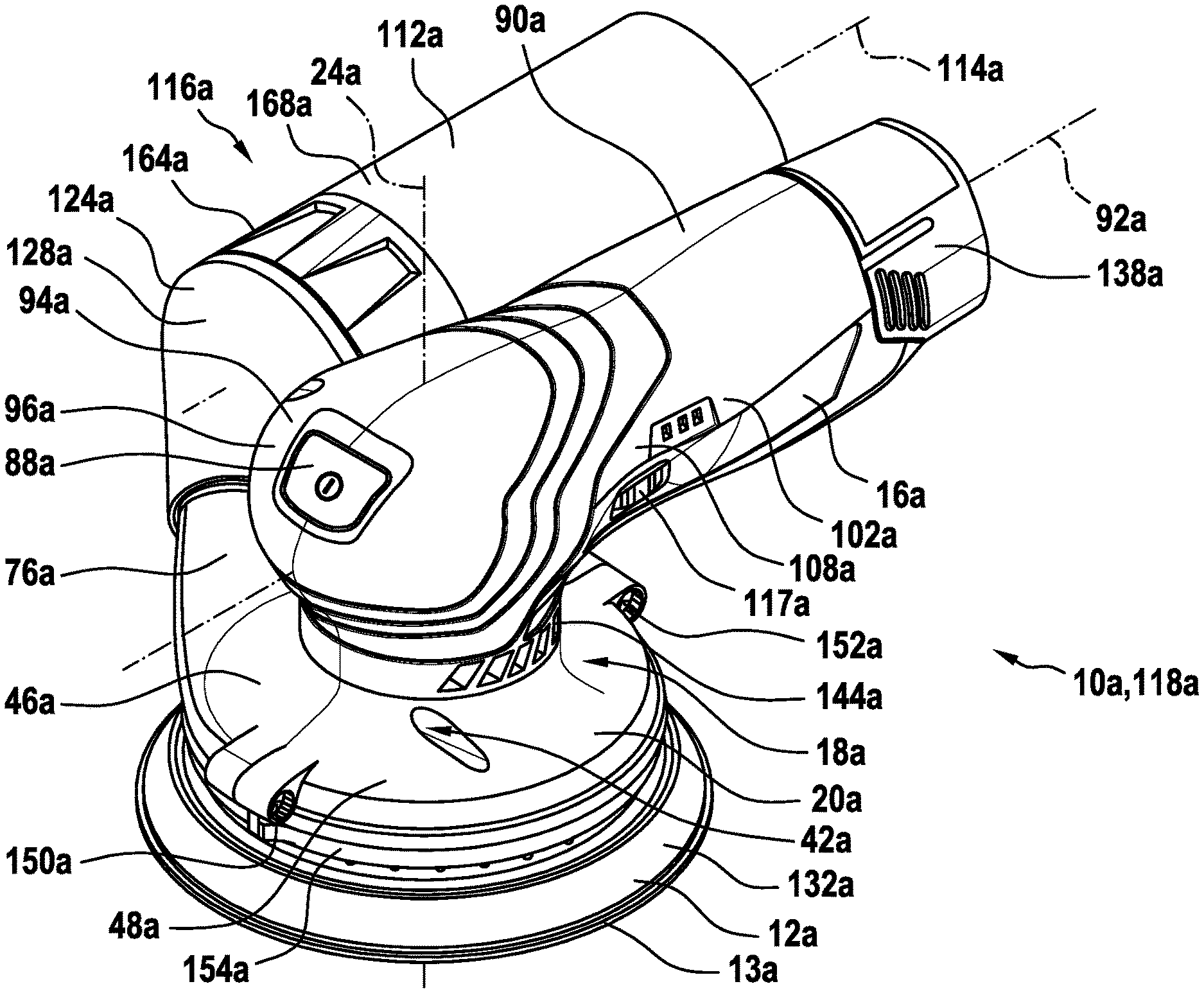
[0023] FIG. 1 shows a schematic perspective illustration of a hand-held grinding machine according to the disclosure,
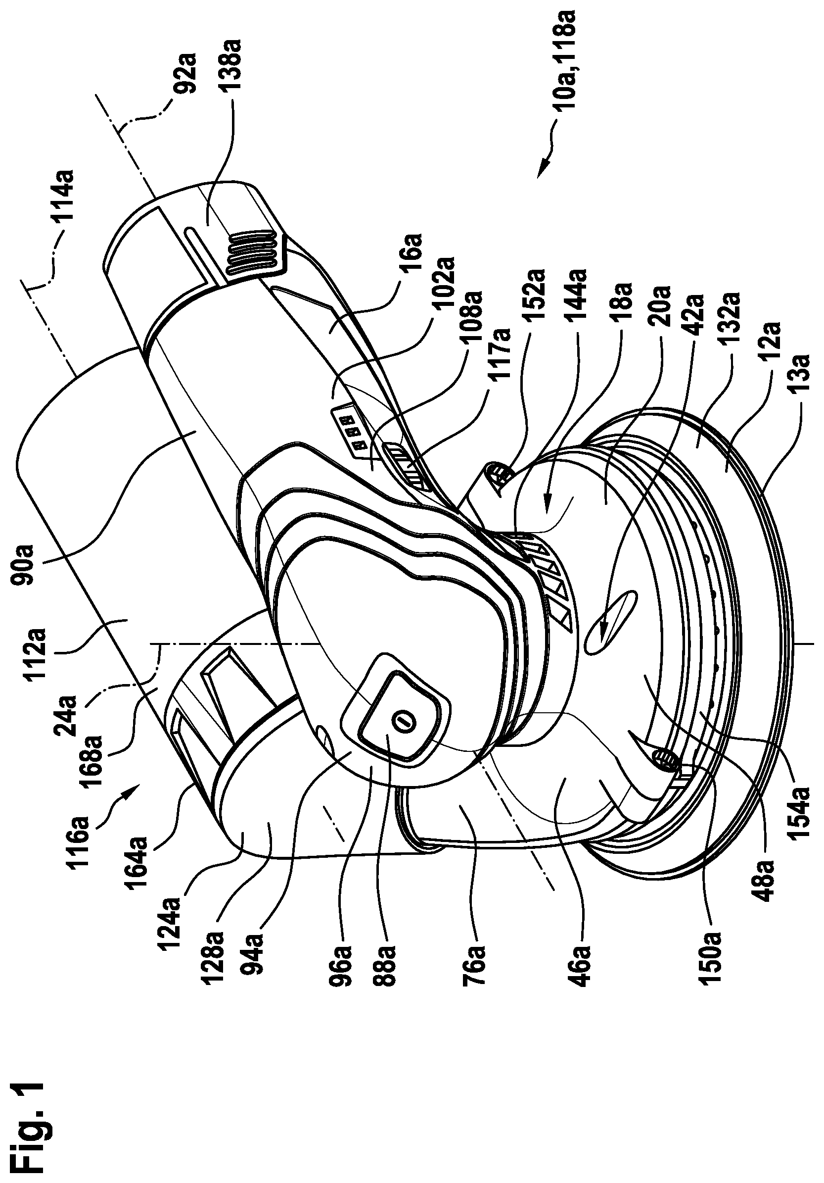
[0024] FIG. 2 shows a schematic plan view of the hand-held grinding machine according to the disclosure,
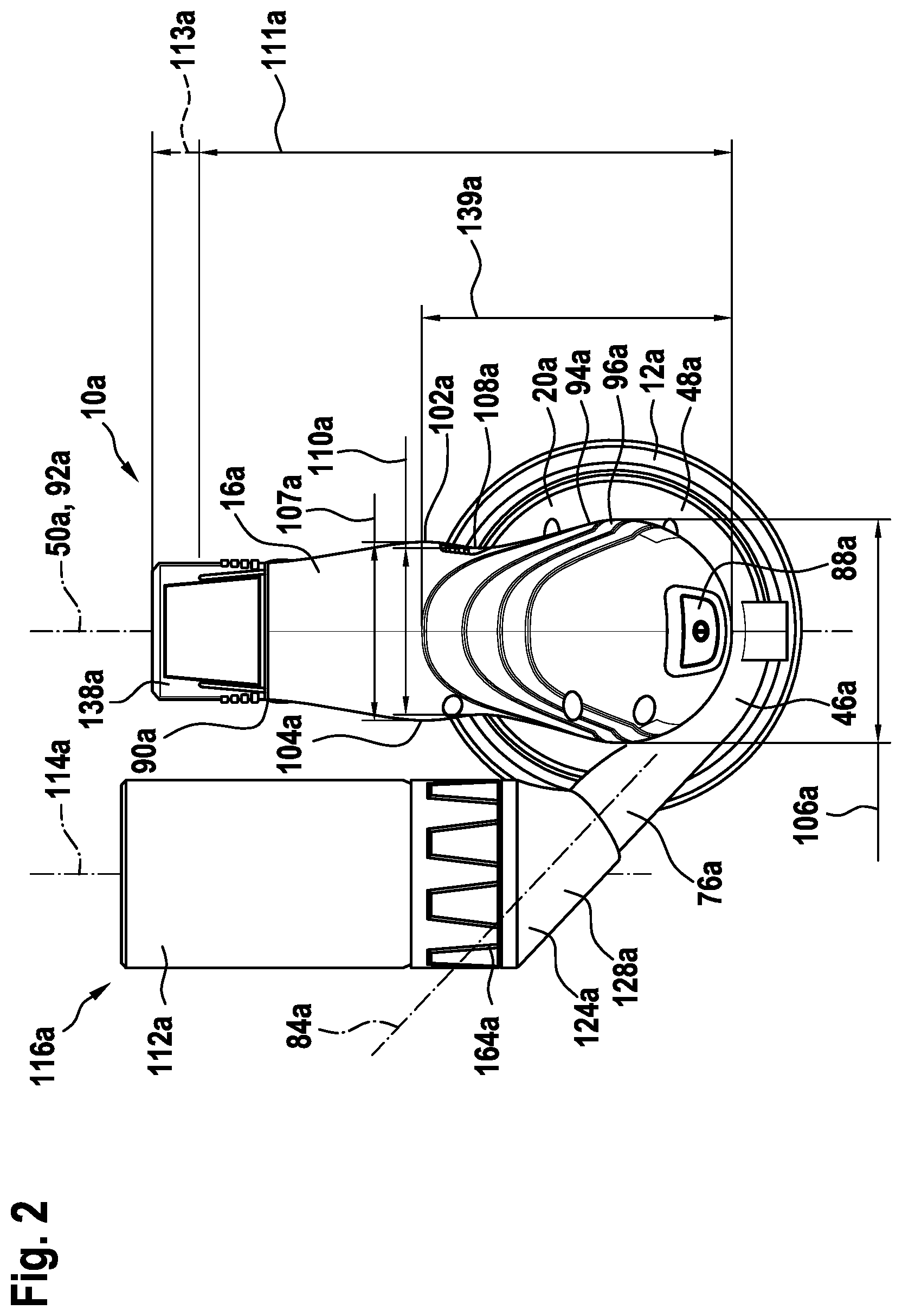
[0025] FIG. 3 shows a schematic longitudinal section of the hand-held grinding machine according to the disclosure,
[0026] FIG. 4 shows a schematic cross section of the hand-held grinding machine according to the disclosure,
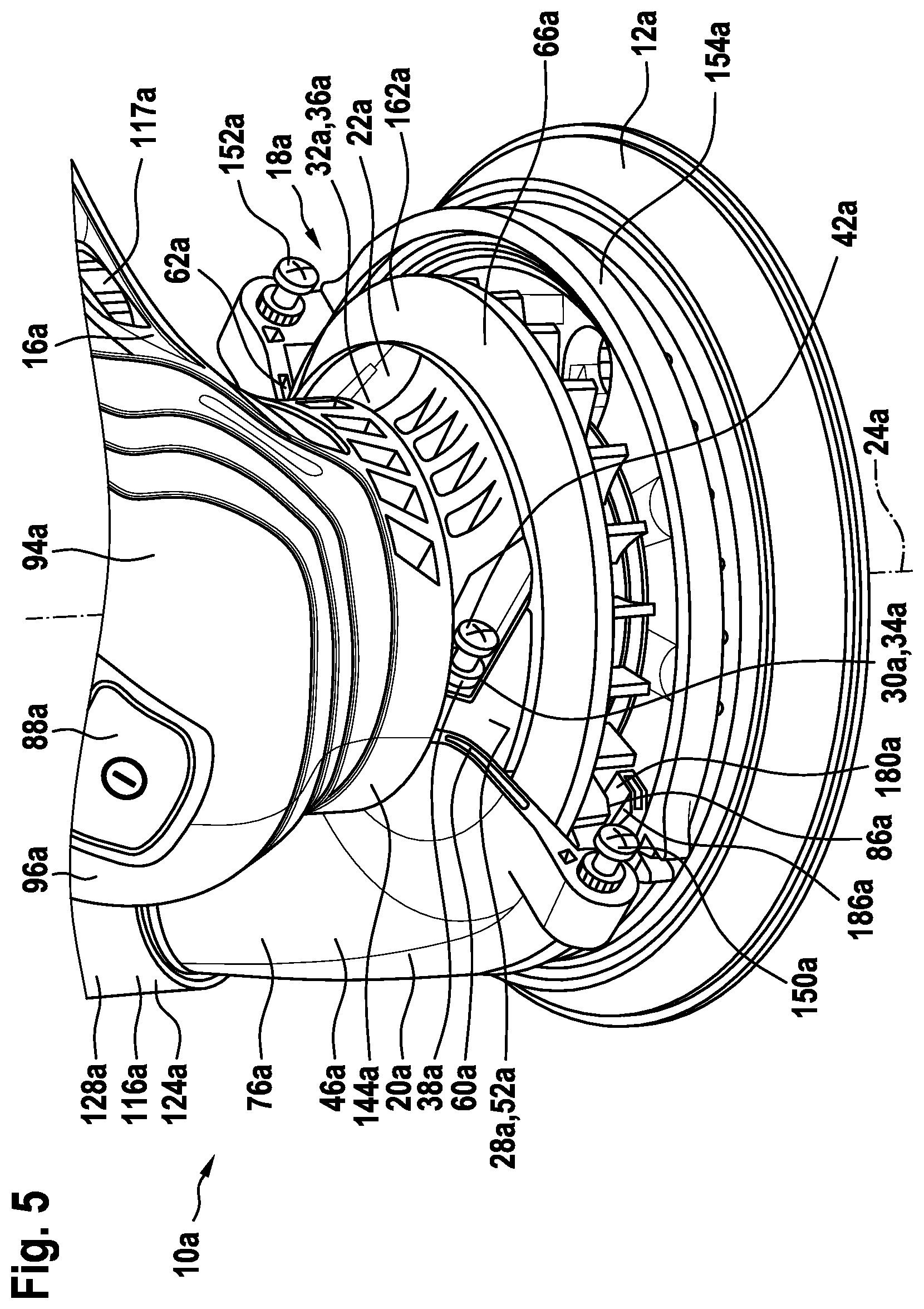
[0027] FIG. 5 shows a schematic illustration of a fastening of a connecting housing unit of the hand-held grinding machine according to the disclosure,
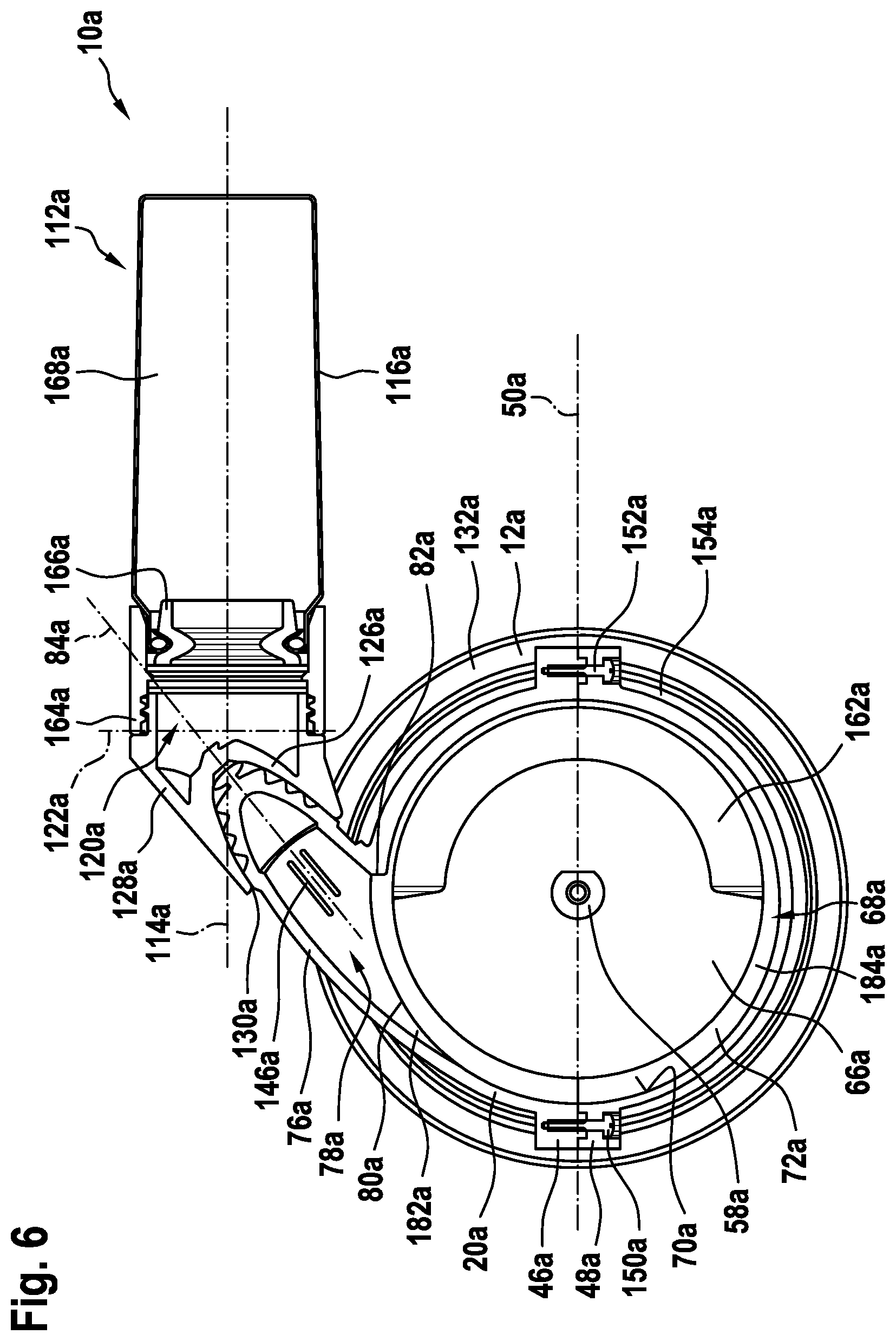
[0028] FIG. 6 shows a schematic cross section of the connecting housing unit,
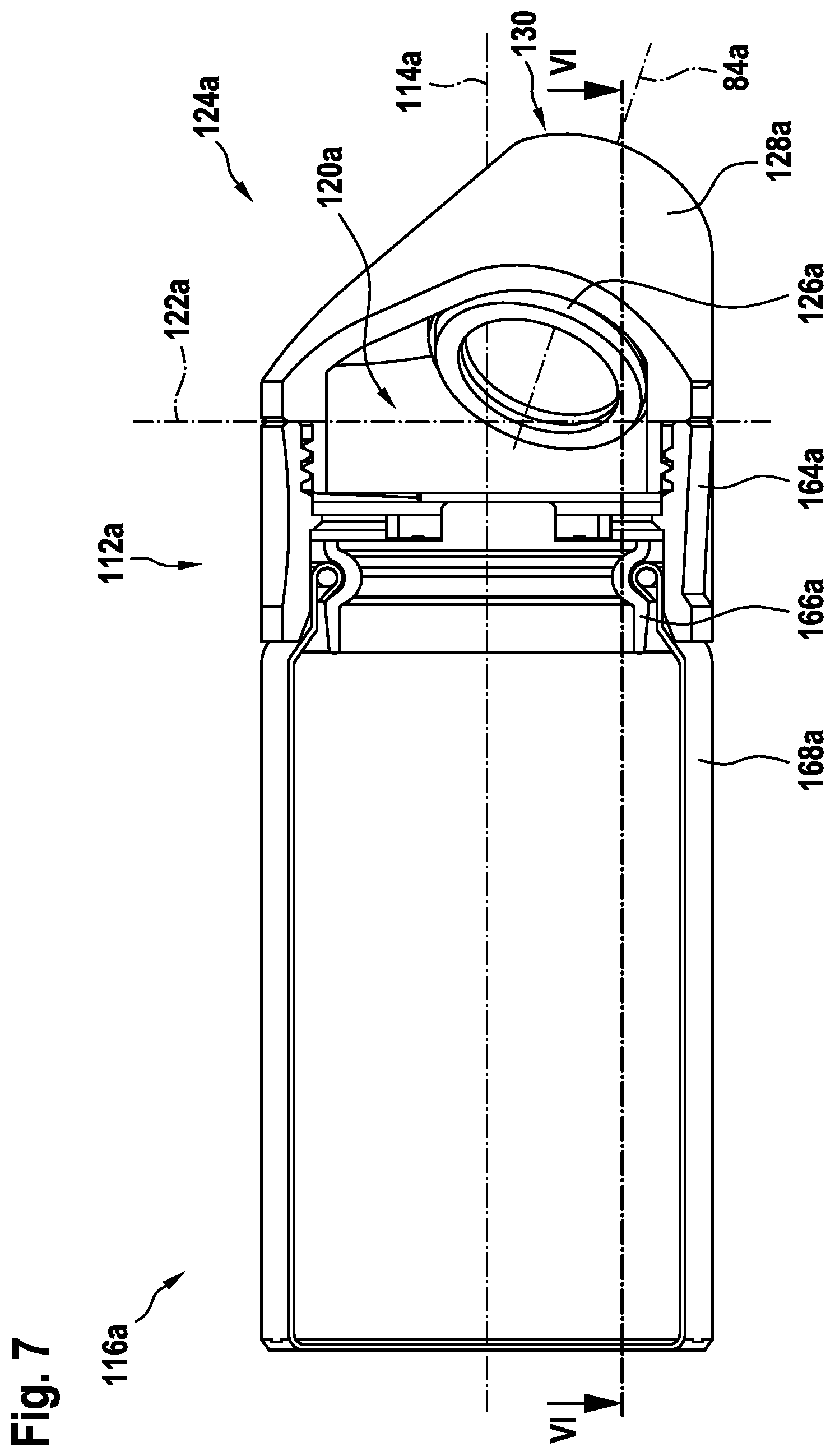
[0029] FIG. 7 shows a schematic longitudinal section of a material collection device of the hand-held grinding machine according to the disclosure,
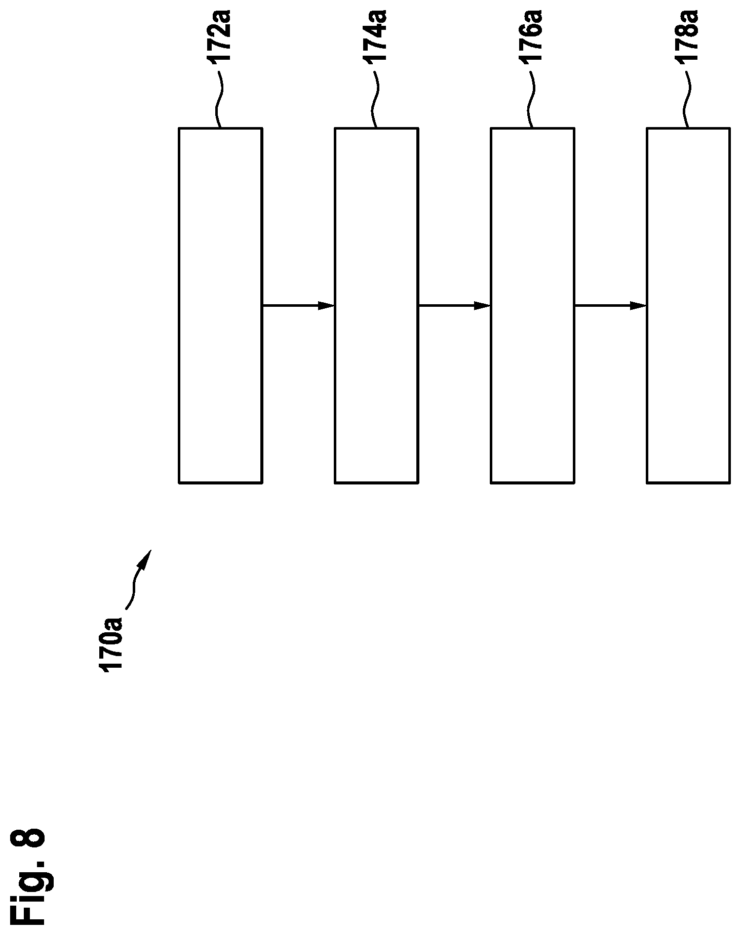
[0030] FIG. 8 shows a schematic flow diagram of a method according to the disclosure for assembling the hand-held grinding machine according to the disclosure,
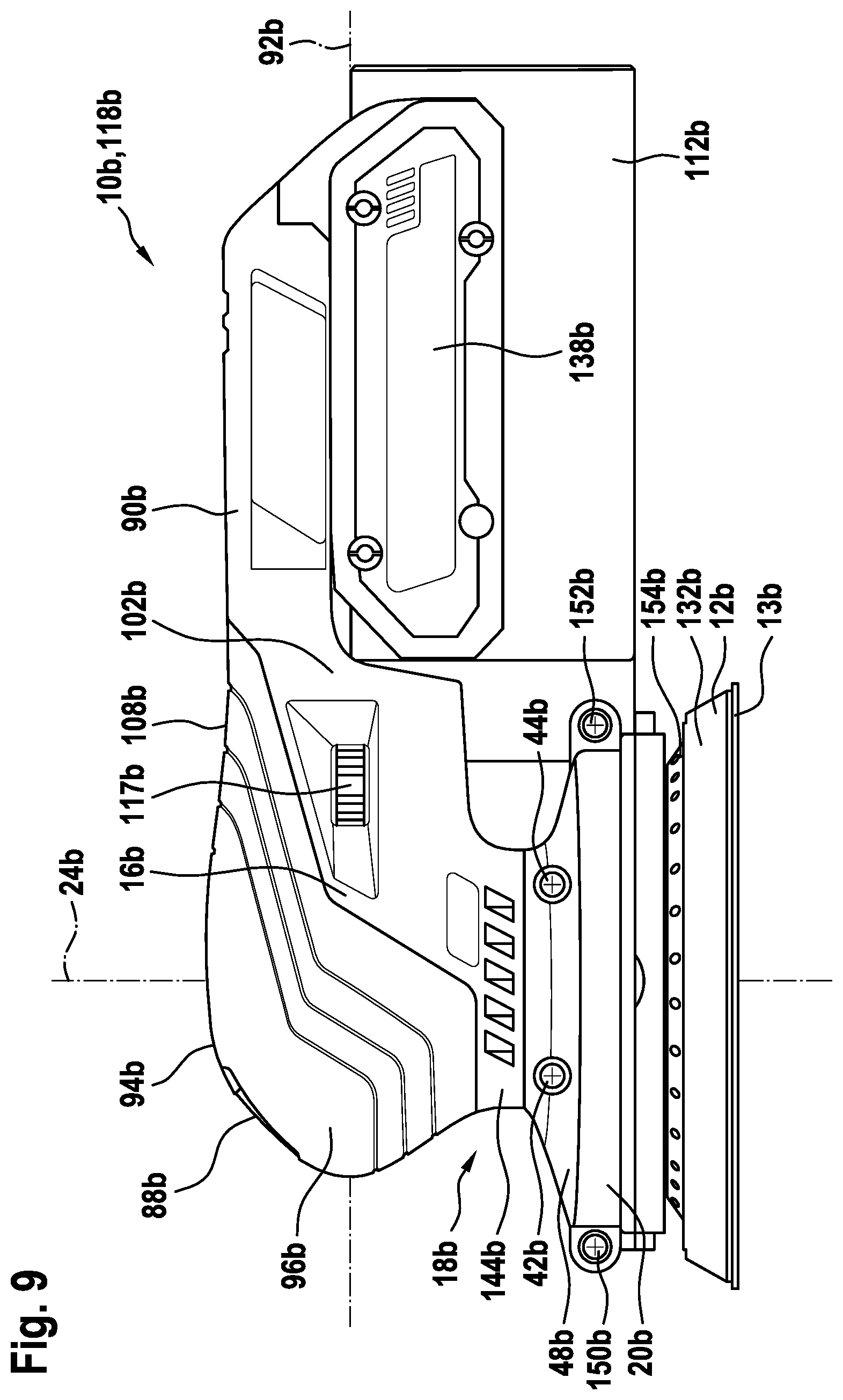
[0031] FIG. 9 shows a schematic illustration of an alternative configuration of a hand-held grinding machine according to the disclosure with an alternative drive device,
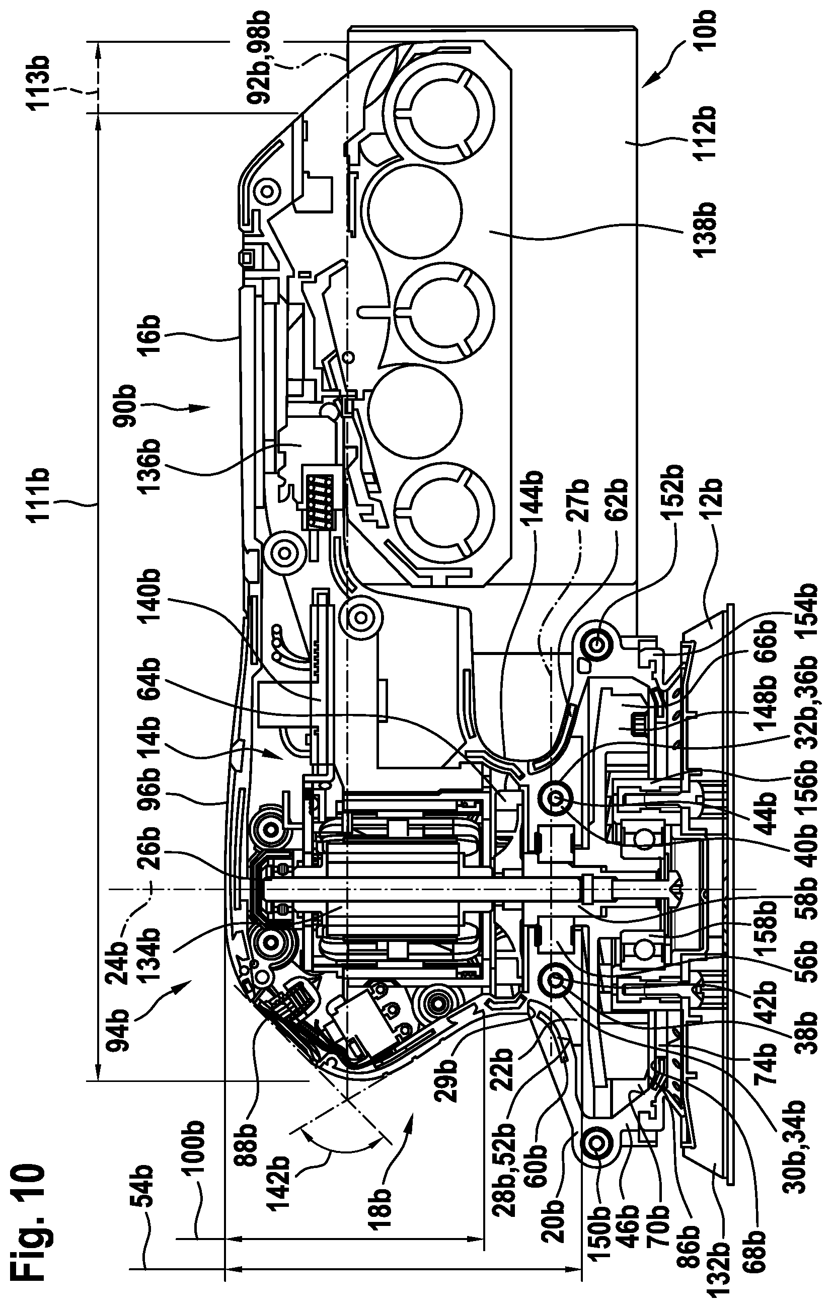
[0032] FIG. 10 shows a schematic longitudinal section of the alternative configuration,
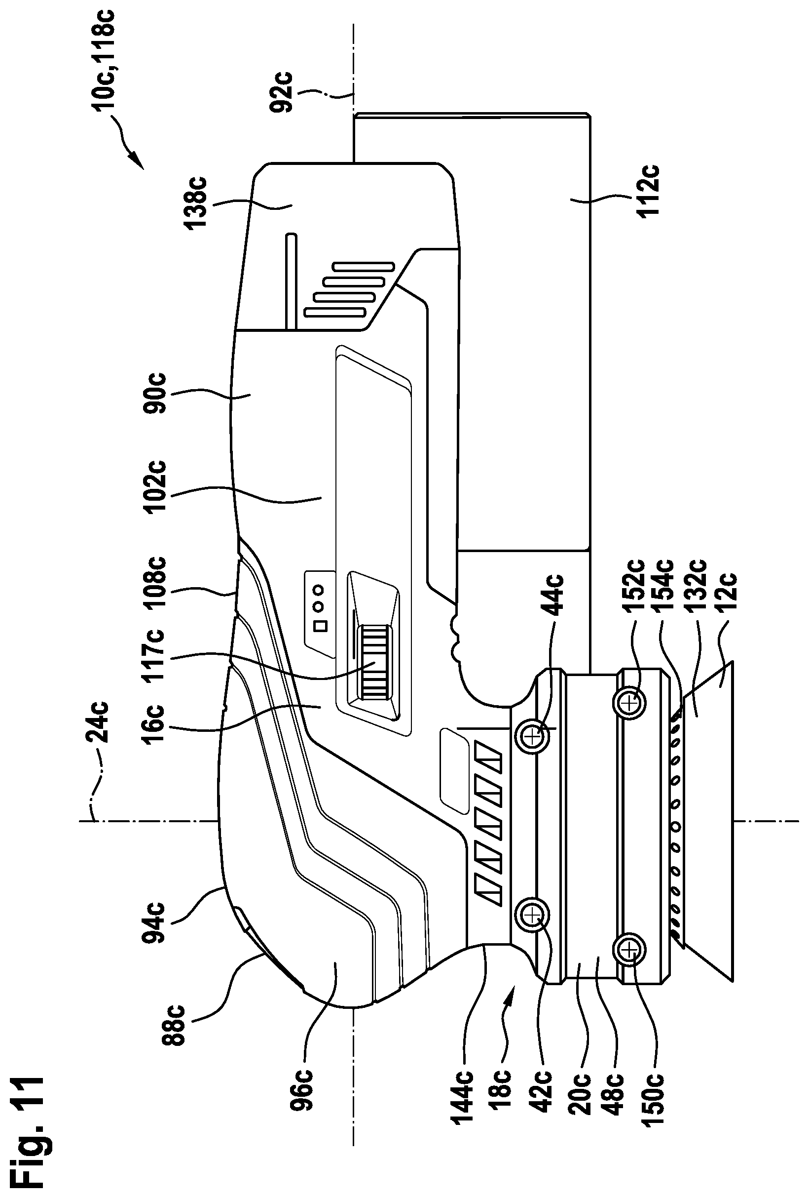
[0033] FIG. 11 shows a schematic illustration of a further alternative configuration of a hand-held grinding machine according to the disclosure with an alternative grinding device,
[0034] FIG. 12 shows a schematic longitudinal section of the further alternative configuration,
[0035] FIG. 13 shows a schematic illustration of a further alternative configuration of a hand-held grinding machine according to the disclosure with a further alternative grinding device, and
[0036] FIG. 14 shows a schematic longitudinal section of the additional alternative configuration.
DETAILED DESCRIPTION
[0037] FIG. 1 shows a hand-held power tool 118a in the form of a hand-held grinding machine 10a. The hand-held grinding machine 10a is in the form in particular of an eccentric grinder. The hand-held grinding machine 10a comprises a grinding device 12a for receiving a grinding means 13a. The grinding device 12a comprises in particular a grinding pad 132a, which is illustrated here by way of example with a diameter of 125 mm. As an alternative, the grinding pad 132a has a diameter of 150 mm or another diameter which is adapted to a size of the grinding means 13a. The hand-held grinding machine 10a comprises a drive device 14a for driving the grinding device 12a (see FIG. 4), which drive device in particular defines an axis of rotation 24a about which the grinding pad 132a can be driven, in particular eccentrically. The hand-held grinding machine 10a comprises a drive housing 16a, which receives the drive device 14a.
[0038] The drive housing 16a has a longitudinal axis 92a, which runs at least substantially perpendicular to the axis of rotation 24a. The drive housing 16a preferably has two drive housing half-shells, which are arranged against one another in an assembly plane 50a which is spanned by the longitudinal axis 92a and the axis of rotation 24a (cf. FIG. 2). The drive housing 16a comprises a longitudinal-axis portion 90a, which is arranged around the longitudinal axis 92a. The longitudinal-axis portion 90a is provided in particular for receiving a rechargeable battery pack 138a, in particular a 12 volt rechargeable battery pack. The drive housing 16a has a front portion 94a. The front portion 94a surrounds an intersection point region of the axis of rotation 24a and the longitudinal axis 92a. The front portion 94a comprises a dome-shaped grip surface 96a. The grip surface 96a is optionally in the form of a soft component, which is arranged, in particular recessed, on a housing basic body of the drive housing 16a. As an alternative, an outer surface of the housing basic body of the drive housing 16a forms the grip surface 96a. The hand-held grinding machine 10a comprises at least one actuating element 88a for controlling the drive device 14a, in particular for switching the drive device 14a on and off. The actuating element 88a is preferably latched in place in an activated state of the drive device 14a. The actuating element 88a is arranged in the grip surface 96a. The actuating element 88a is arranged on a side, facing away from the longitudinal-axis portion 90a, of a plane which is perpendicular to the longitudinal axis 92a and encompasses the axis of rotation 24a.
[0039] The hand-held grinding machine 10a comprises an interface device 18a for operatively connecting, in particular for coupling, the grinding device 12a to the drive device 14a. The interface device 18a is arranged in particular along the axis of rotation 24a on the front portion 94a. The interface device 18a comprises at least one connecting housing unit 20a for at least partially receiving the grinding device 12a. The connecting housing unit 20a is formed separately from the drive housing 16a and the grinding device 12a. The connecting housing unit 20a has at least two main shells 46a, 48a. The main shells 46a, 48a are arranged in particular against one another in the assembly plane 50a. The main shells 46a, 48a are preferably manufactured from plastic. The main shells 46a, 48a preferably have a wall thickness of between 1 mm and 3.5 mm, preferably between 1.5 mm and 2.5 mm, particularly preferably between 1.9 mm and 2.3 mm. The connecting housing unit 20a comprises an ejection port 76a. The ejection port 76a is provided in particular for ejecting material that has been worn off during a grinding process from the connecting housing unit 20a. The ejection port 76a is preferably arranged on one of the main shells 46a. The hand-held grinding machine 10a comprises a material collection device 116a. The material collection device 116a comprises a material collection container 112a, which is preferably air-permeable, for collecting material, such as in particular dust, chips and/or grit, which has been removed by the hand-held grinding machine 10a, and in particular ejected via the ejection port 76a. In at least one configuration of the material collection container 112a, a container longitudinal axis 114a of the material collection container 112a runs at least substantially parallel to the longitudinal axis 92a of the drive housing 16a.
[0040] FIG. 2 shows a view of the hand-held grinding machine 10a along the axis of rotation 24a. The drive housing 16a has a protrusion 102a, 104a to either side of a plane which is perpendicular to the axis of rotation 24a and encompasses the longitudinal axis 92a. A ratio of a maximum protrusion transverse extent 107a of the protrusion 102a to that of the protrusion 104a of the drive housing 16a relative to a largest grip-surface transverse extent 106a of the front portion 94a is between 0.75 and 0.9, in particular between 0.80 and 0.85. The largest grip-surface transverse extent 106a is preferably at the same time the largest transverse extent of the drive housing 16 perpendicular to the axis of rotation 24a and perpendicular to the longitudinal axis 92a. The largest grip-surface transverse extent 106a amounts, in relation to an overall height 54a (cf. FIGS. 3 and 4) of the drive housing 16a, to preferably between 0.8 and 0.95, in particular between 0.85 and 0.9. The largest grip-surface transverse extent 106a preferably amounts to between 65 mm and 85 mm, in particular between 70 mm and 80 mm. In particular, the overall height 54a of the drive housing 16a parallel to the axis of rotation 24a is smaller than 95 mm, preferably smaller than 90 mm, in particular smaller than 85 mm. A maximum machine height parallel to the axis of rotation 24a of the hand-held grinding machine 10a is particularly preferably smaller than 115 mm, in particular smaller than 110 mm.
[0041] The grip surface 96a of the drive housing 16a transitions, proceeding from the front portion 94a, continuously in the direction of the longitudinal axis 92a into a tapering region 108a, delimited by the protrusions 102a, 104a, of the longitudinal-axis portion 90a. A ratio of a maximum tapering transverse extent 110a of the tapering region 108a to the largest grip-surface transverse extent 106a of the front portion 94a is between 0.7 and 0.85, in particular between 0.75 and 0.8. The grip surface 96a of the drive housing 16a extends from the front portion 94a to a plane which is perpendicular to the longitudinal axis 92a and intersects the protrusions 102a, 104a. The grip surface 96a optionally extends along the longitudinal axis 92a over the protrusions 102a, 104a. A plane which is perpendicular to the longitudinal axis 92a and intersects the protrusions 102a, 104a, subdivides a maximum longitudinal extent 111a, 113a of the drive housing 16a in a ratio of between 0.45 and 0.65. In particular, a ratio of a protrusion position 139a of the plane, intersecting the protrusions 102a, 104a, along the longitudinal axis 92a proceeding from a point of the front portion 94a that is furthest away from the maximum longitudinal extent 111a without a rechargeable battery pack 138a amounts to between 0.55 and 0.60. In particular, a ratio of a protrusion position 139a of the plane, intersecting the protrusions 102a, 104a, along the longitudinal axis 92a proceeding from a point of the front portion 94a that is furthest away from the maximum longitudinal extent 113a including a rechargeable battery pack 138a amounts to between 0.5 and 0.55. In particular, the maximum longitudinal extent 111a, 113a parallel to, in particular along, the longitudinal axis 92a is greater than the overall height 54a of the drive housing 16a.
[0042] The material collection container 112a is arranged spaced apart from the grip surface 96a of the drive housing 16a in a plane which is perpendicular to the axis of rotation 24a. In particular, the material collection container 112a is arranged only on the ejector port 76a by means of an assembly unit 124a of the material collection device 116a, in particular in a suspended manner and in particular without further support elements. A transition between the assembly unit 124a and the material collection container 112a is arranged in a plane which is perpendicular to the longitudinal axis 92a with the tapering region 108a. A channel longitudinal axis 84a of the ejector port 76a of the connecting housing unit 20a is aligned at an acute angle, in particular between 40.degree. and 50.degree., preferably between 44.degree. and 46.degree., to the longitudinal axis 92a in a plane which is perpendicular to the axis of rotation 24a. The channel longitudinal axis 84a is preferably in the form of a channel center axis, which runs in particular through a geometric center of gravity of the ejector port 76a. The hand-held grinding machine 10a has an operating element 117a, in particular one which is different from the actuating element 88a, for controlling the grinding device 12a (cf. FIG. 1), for example for matching a rotational speed of the grinding pad 132a. For example, the operating element 117a is in the form of a rotary controller. The operating element 117a and the material collection container 112a are arranged on different sides of the assembly plane 50a spanned by the axis of rotation 24a and the longitudinal axis 92a. The drive housing 16a has a spacing from the material collection container 112a which is between 10 mm and 40 mm, preferably between 15 mm and 35 mm, particularly preferably between 20 mm and 30 mm. The operating element 117a is preferably arranged in the tapering region 108a. The operating element 117a and the actuating element 88a are preferably arranged on different sides of a transverse plane 98a which is perpendicular to the axis of rotation 24a and in which the front portion 94a has the largest grip-surface transverse extent 106a.
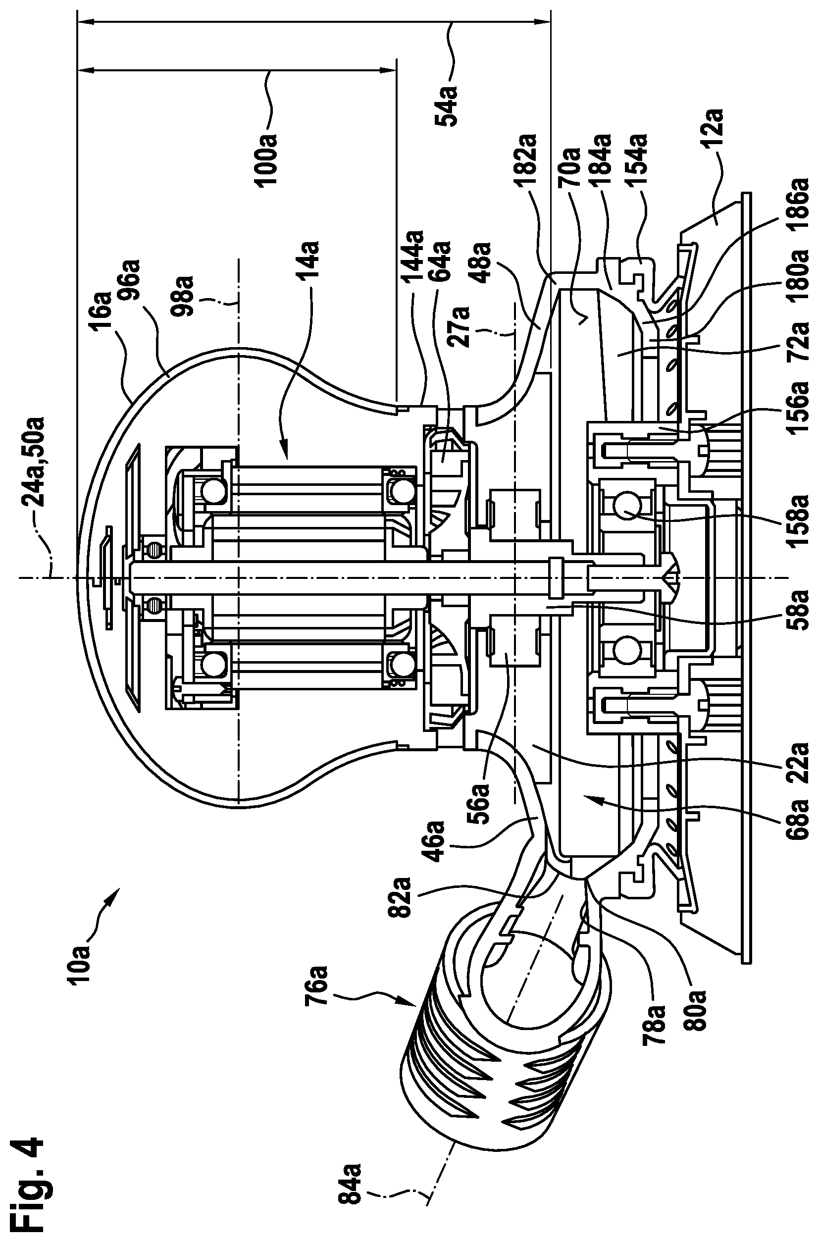
[0043] FIG. 3 shows a longitudinal section of the hand-held grinding machine 10a in the assembly plane 50a and FIG. 4 shows a cross section of the hand-held grinding machine 10a. The grinding device 12a preferably comprises an eccentric, which is driven by a drive shaft 26a. The grinding device 12a preferably comprises an eccentric bearing 158a, which is in particular in the form of a ball bearing. The eccentric bearing 158a optionally comprises a plurality of ball bearings, which are in particular stacked one on top of another along the axis of rotation 24a, or a multi-row, in particular two-row, ball bearing. The eccentric bearing 158a is arranged in particular on the eccentric and engages around the eccentric preferably in a plane which is perpendicular to the axis of rotation 24a. The eccentric bearing 158a is clamped on an offset of the eccentric, in particular by means of an assembly plate and a screw. In particular, a geometric center point of the eccentric bearing 158a is arranged spaced apart from the axis of rotation 24a. In particular, the grinding device 12a comprises an annular grinding-pad holder 156a. The grinding-pad holder 156a is arranged on the eccentric bearing 158a and engages around it preferably in a plane which is perpendicular to the axis of rotation 24a. The grinding-pad holder 156a preferably has a groove, in which the eccentric bearing 158a is arranged. The eccentric bearing is particularly preferably formed such that it is injection molded around the grinding-pad holder 156a. In particular, the grinding-pad holder 156a can be rotated relative to the eccentric. The grinding pad 132a is preferably fastened to the grinding-pad holder 156a, in particular screw-connected in a direction parallel to the axis of rotation 24a. In particular, the grinding device 12a optionally comprises a fan 66a. In particular, the fan 66a is operated by the drive shaft 26a. A blading of the fan 66a preferably surrounds the grinding-pad holder 156a in a plane which is perpendicular to the axis of rotation 24a, wherein the grinding-pad holder 156a projects beyond the fan 66a in a direction of the axis of rotation 24a. The grinding device 12a preferably comprises a slip ring 154a of an elastic material, which slip ring is fastened in a rotationally fixed manner to the connecting housing unit 20a on the connecting housing unit 20a in a groove, and in particular rests on the grinding pad 132a, in particular in order to stabilize a rotational movement of the grinding pad 132a.
[0044] The drive device 14a preferably comprises an electric motor 134a. In particular, the electric motor 134a incorporates a rated voltage of 12 volts. The drive device 14a comprises the drive shaft 26a, which is driven in particular by the electric motor 134a about the axis of rotation 24a. In particular, the drive device 14a comprises an electrical power supply interface 136a, in particular for connecting the rechargeable battery pack 138a. The drive device 14a preferably comprises at least one control electronics 140a, in particular for controlling the electric motor 134a. The electric motor 134a, the control electronics 140a and the electrical power supply interface 136a are preferably arranged along the longitudinal axis 92a, in particular in this order. In particular, the electric motor 134a is arranged in the front portion 94a. In particular, the control electronics 140a is arranged in the tapering region 108a. In particular, the electrical power supply interface 136a is arranged in the longitudinal-axis portion 90a. The drive shaft 26a preferably protrudes proceeding from the front portion 94a into the interface device 18a.
[0045] The actuating element 88a is arranged, in particular recessed, in a partial surface area, arranged obliquely to the longitudinal axis 92a and to the axis of rotation 24a, of the grip surface 96a. The partial surface area which receives the actuating element 88a preferably has an angle of between 40.degree. and 50.degree. to the longitudinal axis 92a. A projection of the actuating element 88a along the axis of rotation 24a in particular does not overlap the electric motor 134a. The actuating element 88a and the grinding device 12a are arranged on different sides of the transverse plane 98a which is at least substantially perpendicular to the axis of rotation 24a and in which the front portion 94a has the largest grip-surface transverse extent 106a. In particular, more than half, preferably more than 66%, particularly preferably more than 75%, of a volume of the electric motor 134a is arranged on that side of the transverse plane 98a which is opposite the actuating element 88a. Between 40% and 60% of a volume of a receiving region of the electrical power supply interface 136a for receiving the rechargeable battery pack 138a is preferably arranged on that side of the transverse plane 98a which is opposite the actuating element 88a. In particular, the partial surface area, surrounding the actuating element 88a, of the grip surface 96a is flattened, in particular has a planar form in sections, in the assembly plane 50a. The front portion 94a of the transverse plane 98a preferably has a continuously curved profile. Partial surface areas of the grip surface 96a, one of which surrounds the actuating element 88a and which terminate the front portion 94a along the longitudinal axis 92a, are arranged at a front angle 142a of between 95.degree. and 110.degree. to one another. The front angle 142a is in particular in the assembly plane 50a. In particular, the partial surface areas terminating the front portion 94a are arranged on different sides of the transverse plane 98a which faces the largest grip-surface transverse extent 106a and runs perpendicular to the axis of rotation 24a.
[0046] A ratio of a maximum grip-surface height 100a, parallel to the axis of rotation 24a, of the grip surface 96a to the overall height 54a, parallel to said maximum grip-surface height, of the drive housing 16a, is between 0.65 and 0.8 and preferably between 0.7 and 0.75. In particular, the grip surface 96a extends in a direction of the axis of rotation 24a as far as an end of the electric motor 134a that faces the grinding device 12a. The drive device 14a preferably comprises a drive fan 64a, in particular for cooling the electric motor 134a. The drive fan 64a is arranged on the axis of rotation 24a between the electric motor 134a and the interface device 18a. The grip surface 96a preferably extends in a direction of the axis of rotation 24a as far as a fan portion 144a of the drive housing 16a, in which ventilation openings for sucking in and/or blowing out air through the drive fan 64a are arranged. The grip-surface height 100a preferably decreases, in particular continuously, in a direction of the longitudinal axis 92a (cf. also FIG. 5). The drive fan 64a and the longitudinal-axis portion 90a are preferably arranged, in particular completely, on different sides of a plane which is perpendicular to the axis of rotation 24a. The front portion 94a preferably tapers in a direction of the axis of rotation 24a to the fan portion 144a. In particular, the actuating element 88a projects along the longitudinal axis 92a at least partially beyond the fan portion 144a. A unit composed of the drive housing 16a and the connecting housing unit 20a preferably has, on the fan portion 144a, a cross section, perpendicular to the axis of rotation 24a, between the actuating element 88a and the grinding device 12a that has the smallest surface area. In particular, the fan portion 144a has a maximum transverse extent perpendicular to the axis of rotation 24a of less than 65 mm, preferably less than 60 mm, particularly preferably less than 55 mm.
[0047] The interface device 18a comprises a docking interface 22a, which is arranged on the drive housing 16a. The connecting housing unit 20a engages around the docking interface 22a in a fixing plane 27a perpendicular to the axis of rotation 24a of the drive shaft 26a of the drive device 14a. The docking interface 22a has, in the fixing plane 27a, at least one axial form-fitting element 28a, 29a, 30a, 32a for forming a form fit, parallel to the axis of rotation 24a, with the connecting housing unit 20a. A projection of the axial form-fitting element 28a, 29a, 30a, 32a along the axis of rotation 24a is at least substantially completely inside the drive housing 16a. In particular, the docking interface 22a comprises a plurality of axial form-fitting elements 28a, 29a, 30a, 32a, the projections of which along the axis of rotation 24a are at least substantially completely inside the drive housing 16a. In particular, a projection of the entire docking interface 22a is at least substantially completely inside the drive housing 16a. The docking interface 22a is preferably arranged along the axis of rotation 24a on the front portion 94a. In particular, the fan portion 144a is arranged between the front portion 94a and the docking portion 22a. The docking interface 22a is preferably materially bonded to the drive housing 16a. In particular, the overall height 54a of the drive housing 16a refers to an extent which is parallel to the axis of rotation 24a and also includes the docking interface 22a.
[0048] The docking interface 22a, as axial form-fitting element 30a, 32a, comprises a fixing recess 34a, 36a. The fixing recess 34a, 36a preferably extends at least substantially parallel to the fixing plane 27a. In particular, the fixing recess 34a, 36a is provided to receive a fixing element 38a, 40a of the connecting housing unit 20a and a separately formed fixing element 42a, 44a. The fixing element 38a, 40a of the connecting housing unit 20a is in the form of a sleeve, particularly preferably a screw boss. The sleeve is designed to receive the separately formed fixing element 42a, 44a. The separately formed fixing element 42a, 44a is preferably in the form of a screw. An overall receiving length of the sleeve corresponds in particular substantially, but in particular not completely, to a length of the separately formed fixing element 42a, 44a. In particular, the sleeve comprises two sleeve portions, one of which is arranged on each of the two main shells 46a, 48a, with the result that there is an air gap between the two sleeve portions. In particular, the main shells 46a, 48a are fastened to the docking interface 22a under tension by tightening the separately formed fixing element 42a, 44a in the sleeve. In particular, the separately formed fixing element 42a, 44a engages in, and in particular through, the docking interface 22a. In the fixing plane 27a, the docking interface 22a preferably comprises at least two, in particular exactly two, copies of the fixing element 38a, 40a per main shell 46a, 48a and in particular at least two, in particular exactly two, copies of the separately formed fixing element 42a, 44a, which are arranged in particular on different sides of a plane which is perpendicular to the longitudinal axis 92a and encompasses the axis of rotation 24a. The connecting housing unit 20a optionally comprises at least one additional fixing element 150a, 152a, which is provided to fasten the main shells 46a, 48a to one another at a position spaced apart from the fixing plane 27a. The connecting housing unit 20a preferably comprises at least two additional fixing elements 150a, 152a, which are arranged in particular between the fixing plane 27a, in particular between that end of the docking interface 22a which faces the grinding pad 132a, and the grinding pad 132a. In particular, the additional fixing elements 150a, 152a are in the form of screws. Additional fixing recesses for the main shells 46a, 48a for receiving the additional fixing elements 150a, 152a are preferably arranged in a plane which is parallel to the fixing plane 27a and comprises the greatest transverse extent of the connecting housing unit 20a in the assembly plane 50a.
[0049] Perpendicular to the axis of rotation 24a, the docking interface 22a, as axial form-fitting element 28a, encompasses a docking cross section which tapers along the axis of rotation 24a in a direction away from the grinding device 12a and in particular leading toward the fan portion 144a. In particular, the fixing recess 34a, 36a is arranged between a maximum cross section of the docking interface 22a perpendicular to the axis of rotation 24a and a minimum cross section of the docking interface 22a perpendicular to the axis of rotation 24a. The docking interface 22a preferably comprises a contact surface 52a, which is formed on a surface of the docking interface 22a that forms the taper. The contact surface 52a faces away in particular from the grinding device 12a and faces in particular the drive device 14a. The main shells 46a, 48a have in particular a mating surface, complementary to the contact surface 52a, on one of their respective inner walls. The mating surfaces of the main shells 46a, 48a are arranged in particular on the contact surface 52a and particularly preferably pressed against the contact surface 52a over their surface area by means of the fixing elements 42a. At a boundary, which is at least substantially perpendicular to the axis of rotation 24a, to the drive housing 16a, in particular to the fan portion 144a, the docking interface 22a, as axial form-fitting element 29a, has a smaller cross section than the drive housing 16a. In particular, a difference in the cross sections of the docking interface 22a and of the drive housing 16a at the boundary corresponds to a wall thickness, in particular twice the wall thickness, of the connecting housing unit 20a. A portion of the main shells 46a, 48a which forms the mating surfaces extends preferably along the contact surface to the boundary. The connecting housing unit 20a is arranged at least substantially flush with the drive housing 16a on the docking interface 22a. The docking interface 22a, in particular the contact surface 52a, encompasses at least 10% to 20% of the overall height 54a of the drive housing 16a including the docking interface 22a parallel to the axis of rotation 24a. It is preferably the case that a ratio of a docking height of the docking interface 22a parallel to the axis of rotation 24a to a maximum transverse extent, in particular a maximum diameter, of the docking interface 22a perpendicular to the axis of rotation is between 0.1 and 0.3, preferably between 0.15 and 0.2. It is preferably the case that a ratio of the docking height of the docking interface 22a parallel to the axis of rotation to a minimum transverse extent, in particular a minimum diameter, of the docking interface 22a perpendicular to the axis of rotation 24a is between 0.15 and 0.35, preferably between 0.2 and 0.25. It is preferably the case that a spacing parallel to the axis of rotation 24a between the maximum transverse extent and the minimum transverse extent of the docking interface 22a perpendicular to the axis of rotation 24a corresponds to at least 60%, preferably more than 75%, of the docking height.
[0050] The contact surface 52a runs transversely to the fixing plane 27a and has a curved form. The mating surface has a curvature which complements the contact surface 52a. The curvature of the contact surface 52a and in particular of the mating surface preferably have a concave form with respect to the axis of rotation 24a. A radius of curvature which describes the contact surface 52a and in particular the mating surface runs outside the docking interface 22a and in particular through the connecting housing unit 20a. The radius of curvature amounts to between 5 mm and 15 mm, preferably between 9 mm and 10 mm. A curvature center point which is part of the radius of curvature preferably lies outside the connecting housing unit 20a. The wall thickness of the connecting housing unit 20a optionally decreases along the curvature in the direction of the drive housing 16a. As an alternative, the wall thickness of the connecting housing unit 20a is constant along the curvature. The contact surface 52a preferably encompasses a planar contact portion, which continues the curvature of the docking interface 22a tangentially in the direction of the grinding pad 132a. In particular, the planar contact portion of the contact surface 52a is inclined with respect to the fixing plane 27a at an angle of between 10.degree. and 20.degree. in the direction of the grinding pad 132a. A portion of the main shells 46a, 48a that forms the mating surfaces preferably extends over the planar contact portion, in particular at the same angle to the fixing plane 27a as the planar contact portion of the contact surface 52a. This extent of the main shells 46a, 48a continues in particular as far as one end of the connecting housing unit 20a in this direction or as far as the additional fixing recesses or as far as the ejector port 76a. In particular, a top side, facing the drive device 14a, of the main shells 46a, 48a forms a hand placement surface, which is inclined in particular relative to the grinding pad 132a and falls away in particular outward from the axis of rotation 24a, in particular for supporting natural holding in the hand when thumb and index finger are arranged on different sides of the axis of rotation 24a. The main shells 46a, 48a are aligned against one another by means of at least one tongue and groove connection 60a, 62a, which is in particular curved and preferably is convexly formed with respect to the axis of rotation 24a, of the connecting housing unit 20a in the fixing plane 27a.
[0051] FIG. 5 illustrates the interface device 18a without one of the main shells 48a. The docking interface 22a has, as basic body, in particular a rotary body with respect to the axis of rotation 24a. As an alternative, the basic body of the docking interface 22a extends parallel to the longitudinal axis 92a and has in particular an elliptical or tapering cross section perpendicular to the axis of rotation 24a. The docking interface 22a has, recessed in the basic body, depressions, access shafts, in particular for the sleeve of the main shells 46a, 48a and the separately formed fixing element 42a, 44a, and/or ventilation openings.
[0052] It is also clear from FIGS. 3 and 4 that the interface device 18a comprises a gear mechanism element 58a. The gear mechanism element 58a of the interface device 18a is in the form in particular of an eccentric shank. The gear mechanism element 58a of the interface device 18a is preferably formed separately from the drive device 14a and the grinding device 12a. The gear mechanism element 58a of the interface device 18a is preferably pressed on the drive shaft 26a along the axis of rotation 24a and in particular connected to the drive shaft 26a for rotation therewith. The eccentric, in particular together with the already mentioned assembly plate, is preferably screwed on the gear mechanism element 58a of the interface device 18a and in particular connected to the gear mechanism element 58a of the interface device 18a for rotation therewith. As an alternative, the gear mechanism element 58a is formed integrally with the drive shaft 26a or with the eccentric of the grinding device 12a. The docking interface 22a engages around a bearing element 56a of the drive device 14a in the fixing plane 27a, which bearing element is configured for rotatably mounting the gear mechanism element 58a of the interface device 18a. The drive shaft 26a preferably extends along the axis of rotation 24a into the bearing element 56a, in particular through the bearing element 56a. The gear mechanism element 58a preferably surrounds the drive shaft 26a in the fixing plane 27a, such that the drive shaft 26a in particular is not in direct contact with the bearing element 56a. In particular, the bearing element 56a is in the form of a ball bearing. The gear mechanism element 58a of the interface device 18a preferably extends along the axis of rotation 24a through the bearing element 56a. In particular, the gear mechanism element 58a of the interface device 18a has a greater maximum transverse extent perpendicular to the axis of rotation 24a on a side of the fixing plane 27a which faces the drive device 14a than on a side of the fixing plane 27a which faces the grinding device 12a, for the purpose of an axial form fit along the axis of rotation 24a with the bearing element 56a. The fan 66a of the grinding device 12a is preferably arranged on the gear mechanism element 58a of the interface device 18a, in particular for centric rotation about the axis of rotation 24a. The fan 66a is not illustrated in FIG. 4 in order to ensure that an inner wall 70a of the main shells 46a, 48a can be seen.
[0053] The fan 66a has an asymmetrical form for the purpose of forming a gear mechanism element of the grinding device 12a. In particular, the fan 66a forms the eccentric. In particular, the fan 66a has a disk-shaped base plate, which is in particular solid, and to which the blading of the fan 66a is fastened. The base plate preferably faces the docking interface 22a and is arranged in particular in the same plane perpendicular to the axis of rotation 24a as the additional fixing elements 150a, 152a. The blading of the fan 66a preferably faces the grinding pad 132a. In particular, as eccentric the fan 66a has a central shank, which is surrounded by the blading in a plane which is perpendicular to the axis of rotation 24a. In particular, the central shank is arranged on the base plate eccentrically in relation to the base plate. The gear mechanism element 58a of the interface device 18a preferably engages in the central shank, forming the eccentric, of the fan 66a and is connected to it in particular for rotation therewith (cf. FIG. 6). The fan 66a preferably has at least one fan counterbalance 148a, which is arranged inside the blading. In particular, a shape of the fan counterbalance 148a is matched to a shape of the blading. The base plate of the fan 66 preferably has a recess 162a, which is arranged offset with respect to the rest of the base plate at least substantially parallel to the axis of rotation 24a. The recess 162a is in the form in particular of a half-ring. The recess 162a and the fan counterbalance 148a, in particular together with part of the blading, is preferably arranged on the recess 162a. In a section of the fan 66a along a plane encompassing the axis of rotation 24a, the recess 162a and the fan counterbalance 148a are arranged in particular in a half of the fan 66a which comprises a smaller volume fraction of the central shank which is in the form of an eccentric. A height of the blading on the recess 162a parallel to the axis of rotation 24a is preferably smaller than a height of the rest of the part of the blading, in particular with the result that the entire blading of the fan 66a has a common termination plane which is perpendicular to the axis of rotation 24a. The drive fan 64a of the drive device 14a and the fan 66a of the grinding device 12a are arranged on different sides of the axial form-fitting element 28a, 29a, 30a, 32a in the direction of the axis of rotation 24a. In particular, at the boundary the docking interface 22a terminates a receiving space of the drive housing 16a in which the drive fan 64a is arranged. In particular, an end of the docking interface 22a along the axis of rotation 24a delimits a fan receiving region 68a, in which the fan 66a is arranged.
[0054] The grinding device 12a comprises the fan 66a for the purpose of transporting away material removed during a grinding operation. The inner wall 70a, which delimits the fan receiving region 68a, of the connecting housing unit 20a is in the form of a funnel about the axis of rotation 24a of the drive shaft 26a of the drive device 14a in order to guide an air stream created by the fan 66a. In particular, the fan receiving region 68a narrows along the axis of rotation 24a in the direction of the grinding pad 132a proceeding from the plane which is perpendicular to the axis of rotation 24a and in which the additional fixing elements 150a, 152a are arranged. The main shells 46a, 48a of the connecting housing unit 20a at least partially surround the fan 66a in the assembly plane 50a, which is parallel to the axis of rotation 24a. In particular, the main shells 46a, 48a surround the fan 66a, in particular the blading thereof, in a direction parallel to the axis of rotation 24a. In particular, the main shells 46a, 48a comprise at least one base portion 180a, which is arranged between the fan 66a and the grinding pad 132a. The connecting housing unit 20a has an air inlet 74a. The air inlet 74a is preferably arranged in the base portion 180a of the main shells 46a, 48a. In particular, the base portion 180a has a base surface which faces the fan 66a and runs at least substantially perpendicularly to the axis of rotation 24a. A maximum transverse extent of the base surface perpendicular to the axis of rotation 24a is in particular smaller than a maximum transverse extent of the fan 66a perpendicular to the axis of rotation 24a. The grinding-pad holder 156a projects in particular through the air inlet 74a, in particular without making contact with the main shells 46a, 48a. The eccentric bearing 158a, the gear mechanism element 58a and/or the eccentric are arranged at least substantially flush with the base portion 180a of the main shells 46a, 48a or are arranged set back in the direction of the drive device 14a relative to the base portion 180a.
[0055] The inner wall 70a is segmented in a direction of the axis of rotation 24a. A mouth opening 78a in the ejector port 76a of the connecting housing unit 20a and the air inlet 74a of the connecting housing unit 20a are arranged in different segments of the inner wall 70a. In particular, the mouth opening 78a is arranged in an ejector segment 182a of the connecting housing unit 20a. The inner wall 70a runs in the ejector segment 182a preferably at least substantially perpendicular to the axis of rotation 24a. In particular, the ejector segment 182a is arranged in the plane with the additional fixing elements 150a, 152a. The connecting housing unit 20a preferably comprises at least one guide segment 184a, which is arranged in a direction of the axis of rotation 24a between the ejector segment 182a and the base portion 180a. The inner wall 70a runs in the guide segment 184a in particular at an acute angle to the axis of rotation 24a. The connecting housing unit 20a preferably comprises at least one further guide segment 186a, which is arranged between the guide segment 184a and the base portion 180a. In particular, the inner wall 70a in a further guide segment 186a has an angle in relation to the axis of rotation 24a which is larger than the angle of the guide segment 184a in relation to the axis of rotation 24a. In particular, the portions of the ejector segment 182a, the guide segment 184, the further guide segment 186a and the base portion 180a and the portion, forming the mating surface, of one of the main shells 46a, 48a are formed integrally with one another.
[0056] The connecting housing unit 20a has a conical spiral track 72a arranged on the inner wall 70a. The spiral track 72a leads in particular from the air inlet 74a of the connecting housing unit 20a in a direction of the axis of rotation 24a to the ejector port 76a of the connecting housing unit 20a. In particular, the conical spiral track 72a is arranged in the guide segment 184a. FIG. 6 shows a cross section, perpendicular to the axis of rotation 24a, through the ejector segment 182a. The fan receiving region 68a preferably has an asymmetrical form. On account of the spiral track 72a, in a plane which is perpendicular to the axis of rotation 24a, the inner wall 70a has in particular a spacing from the axis of rotation 24a which is dependent on an angular position with respect to the axis of rotation 24a. The mouth opening 78a of the ejector port 76a, together with the inner wall 70, in particular forms a separating edge 82a, which runs at least substantially parallel to the axis of rotation 24a. The spacing between the inner wall 70a and the axis of rotation 24a is at its smallest at the separating edge 82a. The spacing between the inner wall 70a and the axis of rotation 24a preferably increases continuously or remains constant in sections. The spacing between the inner wall 70a and the axis of rotation 24a particularly preferably increases linearly with an angular difference in relation to an angular position of the separating edge 82a, illustrated here in particular in the clockwise direction. The spiral track 72a is optionally formed in only one of the main shells 48a, while the spacing of the guide segments 184a is kept constant in sections in the main shell 46a with the ejector port 76a. The conical spiral track 72a preferably has a pitch parallel to the axis of rotation 24a with which the spiral track 72a in at most one revolution, preferably a half-revolution, leads from the further guide segment 186a to the mouth opening 78a. The guide segment 184a, forming the spiral track 72a, of the inner wall 70a has an angle of between 25 and 40.degree., preferably between 30.degree. and 35.degree., in relation to the axis of rotation 24a in a plane which encompasses the axis of rotation 24.
[0057] The spiral track 72a, in particular the guide segment 184a, in a projection along the axis of rotation 24a preferably has no overlap with the fan 66a. More than 50%, in particular more than 75%, preferably more than 90%, of the further guide segment 184a in a projection along the axis of rotation 24a is arranged inside the fan 66a. The blading of the fan 66a has a bevel 86a (see FIG. 3). The bevel 86a is arranged transversely to the axis of rotation 24a and at least substantially parallel to the further guide segment 186a of the inner wall 70a. The inner wall 70a in the further guide segment 186a and in particular the bevel 86a preferably has an angle in relation to the axis of rotation 24a in a plane which encompasses the axis of rotation 24a of between 50.degree. and 70.degree., in particular between 55.degree. and 65.degree..
[0058] A further separating edge 80a, which is formed by the mouth opening 78a of the ejector port 76a of the connecting housing unit 20a, runs at least substantially perpendicularly to the axis of rotation 24a. In particular, the further separating edge 80a separates the ejector segment 182a from the guide segment 184a. The further separating edge 80a continues in particular the spiral path 72a in the region of the mouth opening 78a as far as the separating edge 82a with a constant spacing from the axis of rotation 24a. The further separating edge 80a is arranged in particular at a height along the axis of rotation 24a between the base plate of the fan 66a and the termination plane of the blading. The separating edge 82a, which is formed by the mouth opening 78a of the ejector port 76a of the connecting housing unit 20a and runs at least substantially parallel to the axis of rotation 24a, has a tapering form and has a radius of curvature of less than 10 mm, preferably of less than 3 mm, particularly preferably of less than 2 mm. The radius of curvature of the separating edge 82a is in particular in a plane which is perpendicular to the axis of rotation 24a. The radius of curvature of the separating edge 82a, in particular independently of a precise shaping of the separating edge 82a, describes a smallest imaginary circle, which rests against both the inner wall 70a which faces the fan 66a and an inner wall of the ejector port 76a. Tangents which rest against the inner wall 70a and the inner wall of the ejector port 76a preferably form an angle of between 45.degree. and 65.degree., preferably between 55.degree. and 60.degree., in a plane which is perpendicular to the axis of rotation 24a.
[0059] The channel longitudinal axis 84a runs centrally through an ejector port 76a and predefines in particular a main flow direction of air through the ejector port 76a. A projection of the channel longitudinal axis 84a along the axis of rotation 24a preferably rests tangentially against the fan 66a on an outer contour thereof. The projection of the channel longitudinal axis 84a along the axis of rotation 24a preferably forms an angle of between 40.degree. and 50.degree., particularly preferably between 44.degree. and 46.degree., in relation to the assembly plane 50a. An inner wall, situated opposite the separating edge 82a, of the ejector port 76a extends preferably from the assembly plane 50a to an ejector opening of the ejector port 76a, wherein a spacing between this inner wall and the axis of rotation 24a in the assembly plane 50a is matched to the spacing of the spiral track 72a and becomes continuously greater in the direction of the ejector opening. The channel longitudinal axis 84a of the ejector port 76a of the connecting housing unit 20a forms an acute angle, in particular between 15.degree. and 35.degree., preferably between 20.degree. and 30.degree., with a plane which is perpendicular to the axis of rotation 24a. The channel longitudinal axis 84a is inclined away from the grinding device 12a in a direction of the axis of rotation 24a, in particular proceeding from the mouth opening 78a. At the mouth opening 78a, the ejector port 76a has in particular a rectangular cross section perpendicular to the channel longitudinal axis 84a. At the ejector opening, the ejector port 76a preferably has a circular cross section perpendicular to the channel longitudinal axis 84a. A protective device 146a, in particular in the form of webs parallel to the channel longitudinal axis 84a, for preventing a finger and/or other foreign bodies from entering the ejector port 76a is preferably arranged in a portion of the ejector port 76a that has the rectangular cross section.
[0060] In particular, the material collection device 116a is arranged on the region of the ejector port 76a with the circular cross section. The material collection container 112a has at least one opening 120a for feeding the material into the material collection container 112a. The opening 120a of the material collection container 112a is arranged in an opening plane 122a. The opening plane 122a preferably can be aligned at least substantially perpendicularly to the longitudinal axis 92a in at least one state of the material collection device 116a in which it is arranged at the ejector port 76a. The material collection container 112a preferably comprises exactly one opening 120a in the opening plane 122a. As an alternative, the material collection device 116a in the opening plane 122a comprises a structural element, which divides the opening 120a into small partial openings. The container longitudinal axis 114a of the material collection container 112a is aligned at least substantially perpendicularly to the opening plane 122a. In particular, the container longitudinal axis 114a is in the form of a container center axis, which runs in particular through a geometric center of gravity of the material collection container 122a. In particular, the material collection container 112a has the largest longitudinal extent parallel to, in particular along, the container longitudinal axis 114a. In particular, the material collection container 112a has a rotationally symmetrical form about the container longitudinal axis 114a.
[0061] The material collection device 116a comprises at least one assembly unit 124a for assembling the material collection container 112a on the hand-held grinding machine 10a. The assembly unit 124a comprises a channel element 126a for connection to the ejector port 76a of the hand-held grinding machine 10a. The channel element 126a is provided in particular to be arranged concentrically at the ejector port 76a and has the same channel longitudinal axis 84a as the ejector port 76a in a state in which it is arranged on the ejector port 76a. The channel longitudinal axis 84a of the channel element 126a is arranged transversely to the opening plane 122a of the material collection container 112a in at least one sectional plane running perpendicularly to the opening plane 122a. The channel longitudinal axis 84a is arranged transversely to the opening plane 122a in a further sectional plane which is perpendicular to the sectional plane and the opening plane 122a. In particular, the channel longitudinal axis 84a and the container longitudinal axis 114a are arranged in a skewed manner. The sectional plane in a configuration shown perpendicularly to the axis of rotation 24a can be seen in FIG. 6. FIG. 7 shows the further sectional plane, which is illustrated here in particular offset to the container longitudinal axis 114a. In the state of the material collection device in which it is assembled on the hand-held grinding machine, the container longitudinal axis 114a can be aligned at least substantially parallel to the assembly plane 50a, in particular wherein the container longitudinal axis 114a is aligned parallel to the longitudinal axis 92a. When the container longitudinal axis 114a is aligned parallel to the longitudinal axis 92a, the further sectional plane is arranged in particular parallel to the assembly plane 50a. The container longitudinal axis 114a of the material collection container 112a forms, relative to the assembly plane 50a, an angle which, when added to an angle between the channel longitudinal axis 84a and the container longitudinal axis 114a, forms a total angle of between 80.degree. and 100.degree., particularly preferably of 90.degree.. In particular, the channel longitudinal axis 84a intersects the opening plane 122a in the sectional plane at an angle of between 40.degree. and 50.degree., preferably between 44.degree. and 46.degree.. In particular, the channel longitudinal axis 84a intersects the opening plane 122a in the further sectional plane at an angle of between 15.degree. and 30.degree..
[0062] The channel element 126a is preferably plugged onto the ejector port 76a along the channel longitudinal axis 84a. An inner wall of the channel element 126a and/or an outer wall of the ejector port 76a preferably has structural elements for the purpose of a force fit, which in particular can be released and established by hand, of the channel element 126a with the ejector port 76a, for example webs or nubs with an interference fit and/or a sheathing with an elastic material or the like. The material collection device 116a is preferably arranged on the ejector port 76a such that it can rotate, in particular at least with a moderate expenditure of force. In particular, the moderate expenditure of force necessary for rotating the material collection device 116a at the ejector port 76a exceeds a weight of the material collection device 116a, in particular in a state of the material collection container 112a in which it is filled with material removed by the grinding device 12a. The moderate expenditure of force can preferably be applied by a hand without a tool, and is in particular smaller than 200 N, preferably smaller than 125 N, particularly preferably smaller than 75 N. In particular, the material collection device 116a remains in a current rotational position with respect to the ejector port 76a without manual actuation. A rotation of the material collection device 116a about the channel longitudinal axis 84a causes a relative position of the container longitudinal axis 114a in relation to the axis of rotation 24a and/or of the longitudinal axis 92a to change. In particular, the material collection device 116a is arranged pivotably on the ejector port 76a relative to the drive housing 16a. This makes it possible to advantageously flexibly align the material collection device 116a during the grinding operation such that even surfaces which are difficult to access can be processed.
[0063] The assembly unit 124a comprises an adapter housing 128a. The adapter housing 128a has an asymmetrically tapering form from the opening plane 122a in a direction of the channel longitudinal axis 84a. The channel element 126a projects at least partially into the adapter housing 128a. The channel element 126a has an in particular rotationally symmetrical form in relation to the longitudinal axis 92a. The channel element 126a is preferably recessed completely in the adapter housing 128a. The channel element 126a and the adapter housing 128a are particularly preferably formed in one piece. The adapter housing 128a preferably has an assembly element for fixing the material collection container 112a to the adapter housing 128a. For example, the assembly element is in the form of a thread, preferably an external thread. In particular, the material collection container 112a has an air-permeable container region 168a for collecting the removed material and a fastening ring 164a for fastening the container region 168a to the assembly unit 124a. The fastening ring 164a preferably has an assembly element, for example a thread, in particular an internal thread, for connection to the adapter housing 128a.
[0064] The container region 168a is preferably fixed to the fastening ring 164a by means of a latching and/or screw connection 166a. In particular, the fastening ring 164a delimits the opening 120a. The fastening ring 164a and the adapter housing 128a are preferably arranged at least substantially flush with one another. The adapter housing 128a is in particular in the form of a truncated cone which rests on the fastening ring 164a in a skewed manner and the cone axis of which is aligned coaxially with the channel longitudinal axis 84a. A radius of a top surface of the frustoconical adapter housing 128a is preferably the same as an outer radius of the channel element 126a.
[0065] A maximum adapter longitudinal extent of a portion of the assembly unit 124a that projects beyond the material collection container 112a in a direction of the container longitudinal axis 114a is at least substantially the same as a maximum adapter transverse extent of the assembly unit 124a in the opening plane 122a. In particular, a ratio of the adapter longitudinal extent to the adapter transverse extent is between 50% and 80%, preferably between 60% and 70%. In particular, the adapter housing 128a, in particular an inlet opening 130a of the channel element 126a, projects at most slightly beyond the material collection container 112a in a projection along the container longitudinal axis 114a. In particular, a projection of the adapter housing 128a along the container longitudinal axis 114a is completely inside a smallest imaginary square which specifically completely encloses a projection of the material collection container 112a. In particular, a maximum distance of the inlet opening 130a from the container longitudinal axis 114a is smaller than 2 times an outer radius of the material collection container 112a in the opening plane 122a. In FIG. 6, the material collection container 112a is divided by the sectional plane in a ratio of more than 1:4, and therefore here the diameter of the material collection container 112a is not illustrated and the adapter housing 128a only seemingly projects significantly beyond the material collection container 112a in the direction of the grinding device 12a.
[0066] The outlet opening of the channel element 126a assumes a maximum outlet opening width between 35% and 55%, in particular between 44% and 47%, of a maximum opening width of the opening 120a in the opening plane 122a. A ratio of an internal diameter of the channel element 126a compared to the opening width of the opening 120a preferably amounts to between 35% and 60%, preferably between 45% and 55%. The container longitudinal axis 114a preferably runs through an outlet opening, facing the material collection container 112a, of the channel element 126a. The outlet opening in the channel element 126a is preferably arranged in a plane which runs at least substantially perpendicularly to the channel longitudinal axis 84a and transversely to the opening plane 122a. A geometric center point of the outlet opening in the channel element 126a is arranged offset at least in the further sectional plane in particular with respect to the container longitudinal axis 114a, in particular by a magnitude of 10% to 30% of the maximum opening width.
[0067] The inlet opening 130a of the channel element 126a extends in a plane which runs at least substantially perpendicular to the channel longitudinal axis 84a and in particular transversely to the opening plane 122a. The inlet opening 130a engages in particular around the region of the ejector port 76a with the circular cross section. The ejector port 76a preferably projects into the channel element 126a at least as far as the container longitudinal axis 114a. The inlet opening 130a in the channel element 126a is arranged spaced apart from the container longitudinal axis 114a, running perpendicularly to the opening plane 122a, of the material collection container 112a.
[0068] FIG. 8 shows a flow diagram of a method 170a for assembling the hand-held grinding machine 10a. The method 170a comprises in particular a preassembly step 172a. The method 170a preferably comprises a connection step 174a. The method 170a preferably comprises a main-shell arrangement step 176a. In particular, the method 170a comprises a fixation step 178a. In the preassembly step 172a, in particular the drive device 14a and/or the grinding device 12a are preassembled, in particular independently of one another. In the preassembly step 172a, the drive device 14a is arranged in the drive housing 16a, in particular in a half-shell to be assembled of the drive housing 16a, of the hand-held grinding machine 10a. In the connection step 174a, the gear mechanism element 58a is preferably pressed onto the drive shaft 26a. In the connection step 174a, the grinding device 12a is preferably screwed on the gear mechanism element 58a. In the main-shell arrangement step 176a, a form fit, parallel to the axis of rotation 24a, of the connecting housing unit 20a with the docking interface 22a is formed by means of the axial form-fitting element 28a, 29a, 30a, 32a, arranged in the fixing plane 27a, of the docking interface 22a. In the main-shell arrangement step 176a, the connecting housing unit 20a is arranged on the docking interface 22a so as to engage around the docking interface 22a in the fixing plane 27a which is perpendicular to the axis of rotation 24a. In particular, in the main-shell arrangement step 176a, the main shells 46a, 48a are placed on the docking interface 22a. In particular, the mating surfaces of the main shells 46a, 48a are placed onto the contact surface 52a, wherein the grinding device 12a is arranged at least partially in the connecting housing unit 20a. In the main-shell arrangement step 176a, the sleeve of the main shells 46a, 48a is preferably plugged in the fixing recesses 34a, 36a in the docking interface 22a. The main shells 46a, 48a are placed against one another in particular in the assembly plane 50a. In the fixation step 178a, the separately formed fixing element 42a, 44a is arranged in the sleeve arranged in the fixing recess 34a, 36a and as a result presses the main shells 46a, 48a against one another and, in particular the contact surface 52a, against the docking interface 22a. The fixing elements 42a, 44a, the additional fixing elements 150a, 152 and optionally drive housing fixing elements for connecting the half-shells to be assembled of the drive housing 16a are preferably assembled on the main shells 46a, 48a, the docking interface 22a and/or the drive housing 16a in all cases from the same, single direction which is at least substantially perpendicular to the assembly plane 50a.
[0069] FIGS. 9 to 14 show further exemplary embodiments of the disclosure. The following description and the drawings are substantially restricted to the differences between the exemplary embodiments, it being possible to make reference fundamentally also to the drawings and/or the description of the other exemplary embodiments, in particular in FIGS. 1 to 8, with respect to components with the same designation, in particular with respect to components with the same reference signs. In order to make a distinction between the exemplary embodiments, the letter a is appended to the reference signs of the exemplary embodiment in FIGS. 1 to 8. The letter a is replaced by letters b to d in the exemplary embodiments in FIGS. 9 to 14.
[0070] FIG. 9 shows an external view and FIG. 10 shows a longitudinal section of a hand-held grinding machine 10b in the form of an eccentric grinder. The hand-held grinding machine 10b comprises a grinding device 12b, which is in particular identical to the grinding device 12a of the previous exemplary embodiment. The hand-held grinding machine 10b has a drive device 14b, in particular with an electric motor 134b. In particular, the electric motor 134b incorporates a rated voltage of 18 volts. An electrical power supply interface 136b of the drive device 14b and a longitudinal-axis portion 90b of a drive housing 16b of the hand-held grinding machine 10b is preferably designed for receiving an 18-volt rechargeable battery pack 138b. The hand-held grinding machine 10b comprises an interface device 18b with a docking interface 22b and a connecting housing unit 20b. The connecting housing unit 20b preferably has a counterbalance, which compensates a torque caused by a weight of the rechargeable battery pack 138b, in particular in order to prevent an axis of rotation 24b of the drive device 14b from tilting. The counterbalance is preferably arranged on main shells 46b, 48b of the connecting housing unit 20b, in particular is integrated therein. The main shells 46b, 48b are optionally manufactured from metal in order to form the counterbalance, in particular by means of an aluminum/zinc die-casting process. As an alternative, the main shells 46b, 48b have metal inclusions in a plastic body as counterbalance. The counterbalance and the electrical power supply interface 136b are arranged in particular on different sides of a plane which is perpendicular to a longitudinal axis 92b of the hand-held grinding machine 10b and contains the axis of rotation 24b. A portion of the connecting housing unit 20b with the counterbalance preferably rests against a docking interface 22b of the interface device 18b. In particular, the portion of the connecting housing unit 20b with the counterbalance has a greater wall thickness than the portion of the connecting housing unit 20b that is arranged on the side situated opposite the plane which is perpendicular to the longitudinal axis 92b and encompasses the axis of rotation 24b. The portion of the connecting housing unit 20b with the counterbalance preferably has an outer surface which faces the drive housing 16b and is inclined in the direction of the grinding device 12b by 15.degree. to 30.degree. with respect to a plane which is perpendicular to the axis of rotation 24b. Reference should be made to FIGS. 1 to 8 and the description thereof in terms of further features of the hand-held grinding machine 10b.
[0071] FIG. 11 shows an external view and FIG. 12 shows a longitudinal section of a hand-held grinding machine 10c. The hand-held grinding machine 10c has a drive device 14c and a drive housing 16c, which are formed in particular identically to the drive device 14a and the drive housing 16a, respectively, of the first exemplary embodiment. As an alternative, a grinding device 12c of the hand-held grinding machine 10c, in particular without further adaptation, may also be combined with a drive device and a drive housing 16c, as were shown in the second exemplary embodiment. A grinding pad 132c of the grinding device 12c has a diameter of between 70 mm and 80 mm, preferably between 77 mm and 80 mm, for example. In particular, the entire grinding device 12c and an interface device 18c of the hand-held grinding machine 10c in a projection along an axis of rotation 24c of the drive device 14c lie inside the drive housing 16c. A docking interface 22c of the interface device 18c is formed in particular identically to the docking interfaces 22a, 22b of the previous exemplary embodiments. A connecting housing unit 20c of the interface device 18c is adapted in particular to a height of the grinding device 12c parallel to the axis of rotation 24c. A maximum transverse extent of the connecting housing unit 20c perpendicular to the axis of rotation 24c is preferably insignificantly larger than a maximum transverse extent of the docking interface 22c, in particular is larger only by a wall thickness, in particular twice the wall thickness, of the connecting housing unit 20c. In particular, a portion of the connecting housing portion 20c that runs at least substantially parallel to the axis of rotation 24c is arranged directly on the docking interface. In particular, additional fixing elements 150c, 152c are arranged in a plane parallel to the axis of rotation 24c with a contact surface 52c of the docking interface 22c. A gear mechanism element 58c of the interface device 18c engages through an optional fan 66c along the axis of rotation. In particular, the gear mechanism element 58c is formed integrally with an eccentric of the grinding device 12c to form a drive of the grinding pad 132c. The gear mechanism element 58c engages around an eccentric bearing 158c of the grinding device 12c, in particular in a plane which is perpendicular to the axis of rotation 24c. The eccentric bearing 158c preferably engages around a grinding-pad holder 156c of the grinding device 12c in a plane which is perpendicular to the axis of rotation 24c. The grinding-pad holder 156c receives in particular a continuation of the grinding pad 132c in a direction parallel to the axis of rotation 24c. Reference should be made to FIGS. 1 to 10 and the description thereof in terms of further features of the hand-held grinding machine 10c.
[0072] FIG. 13 shows an external view and FIG. 14 shows a longitudinal section of a hand-held grinding machine 10d. The hand-held grinding machine 10d is in the form in particular of an oscillating grinder. The hand-held grinding machine 10d has a drive device 14d and a drive housing 16d, which are formed in particular identically to the drive device 14a and the drive housing 16a, respectively, of the first exemplary embodiment. As an alternative, a grinding device 12d of the hand-held grinding machine 10d, in particular without further adaptation, may also be combined with a drive device and a drive housing, as are shown in the second exemplary embodiment. A grinding pad 132d of the grinding device 12d is fastened to a connecting housing unit 20d of an interface device 18d of the hand-held grinding machine 10d, in particular by means of an elastic mount 160d. A fan 66d of the grinding device 12d is arranged in a fan housing of the grinding device 12d, which is arranged in particular inside the connecting housing unit 20d. The elastic mount 160d is arranged in particular between the fan housing and the connecting housing unit 20d. A gear mechanism element 58d of the interface device 18d is preferably formed integrally with an eccentric of the grinding device 12d. An eccentric bearing 158d of the grinding device 12d engages in particular around the gear mechanism element 58d in a plane which is perpendicular to an axis of rotation 24d of the drive device 14d. The eccentric bearing 158d is arranged in particular in a guide ring, able to be deflected by the eccentric bearing 158d, of the grinding pad 132d and connected to the guide ring preferably in a force-fitting manner. Reference should be made to FIGS. 1 to 12 and the description thereof in terms of further features of the hand-held grinding machine 10d.
* * * * *
D00000
D00001
D00002
D00003
D00004
D00005
D00006
D00007
D00008
D00009
D00010
D00011
D00012
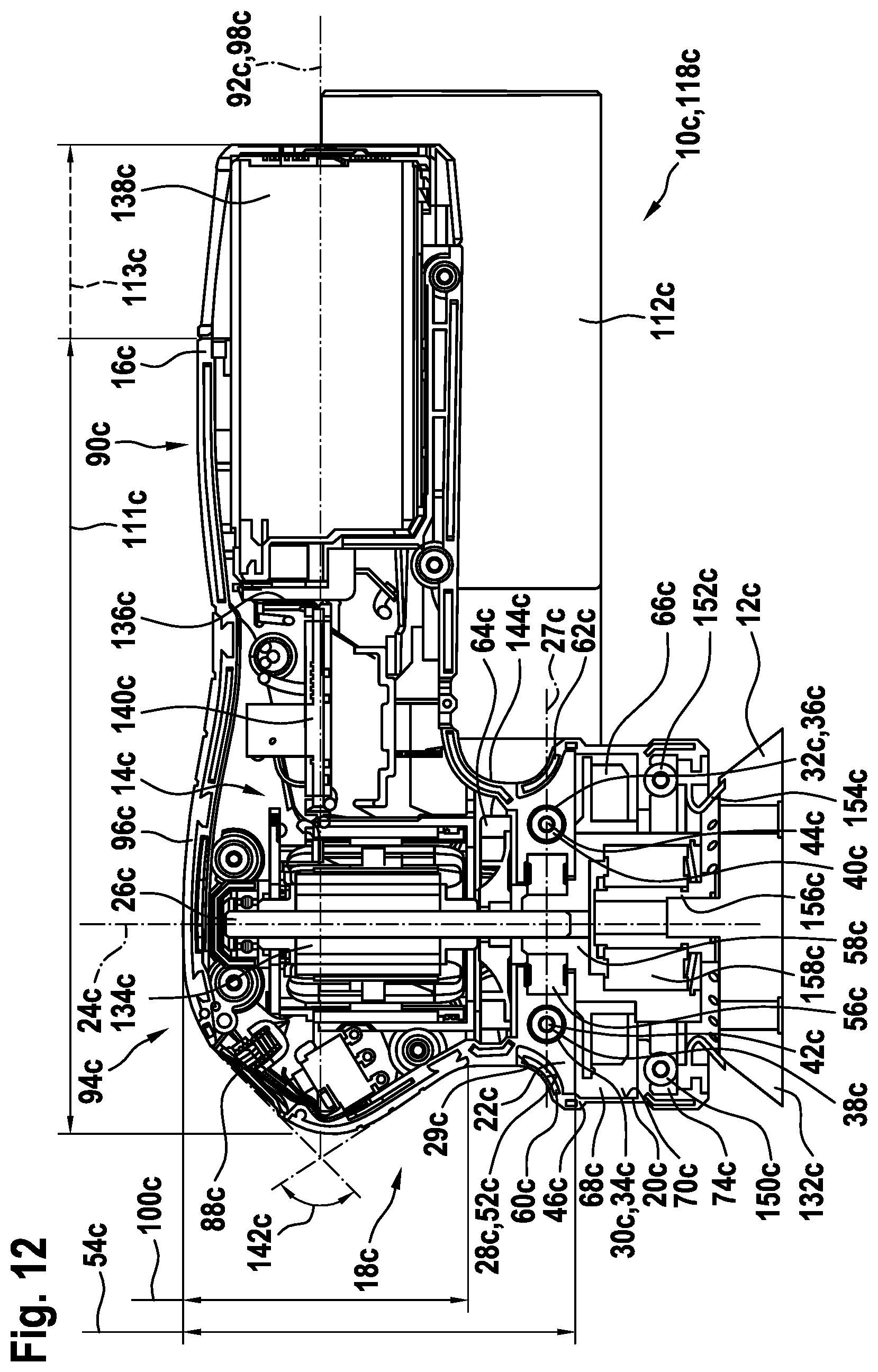
D00013
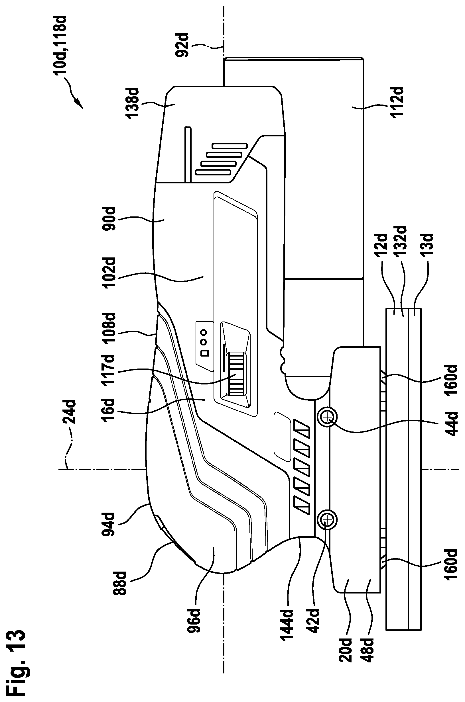
D00014
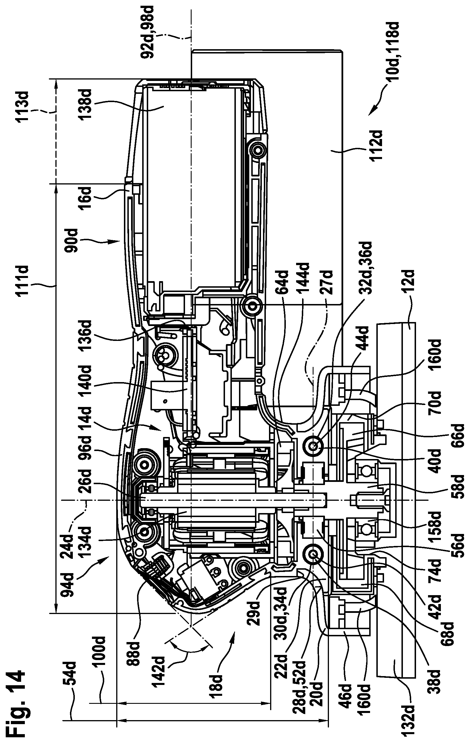
XML
uspto.report is an independent third-party trademark research tool that is not affiliated, endorsed, or sponsored by the United States Patent and Trademark Office (USPTO) or any other governmental organization. The information provided by uspto.report is based on publicly available data at the time of writing and is intended for informational purposes only.
While we strive to provide accurate and up-to-date information, we do not guarantee the accuracy, completeness, reliability, or suitability of the information displayed on this site. The use of this site is at your own risk. Any reliance you place on such information is therefore strictly at your own risk.
All official trademark data, including owner information, should be verified by visiting the official USPTO website at www.uspto.gov. This site is not intended to replace professional legal advice and should not be used as a substitute for consulting with a legal professional who is knowledgeable about trademark law.