Defining And Implementing Sensor Triggered Response Rules
Cohn; Alan Wade ; et al.
U.S. patent application number 17/645889 was filed with the patent office on 2022-04-14 for defining and implementing sensor triggered response rules. The applicant listed for this patent is iControl Networks, Inc.. Invention is credited to Alan Wade Cohn, John Degraffenreid Dial, IV, Gary Robert Faulkner, James Edward Kitchen, David Leon Proft, Corey Wayne Quain.
| Application Number | 20220116242 17/645889 |
| Document ID | / |
| Family ID | 1000006052382 |
| Filed Date | 2022-04-14 |


View All Diagrams
| United States Patent Application | 20220116242 |
| Kind Code | A1 |
| Cohn; Alan Wade ; et al. | April 14, 2022 |
DEFINING AND IMPLEMENTING SENSOR TRIGGERED RESPONSE RULES
Abstract
Systems, methods, and devices for managing sensor event rules are described. Methods may comprise determining a sensor event rule, wherein the sensor event rule comprises a rule sensor identifier and a rule event identifier. Data indicative of a sensor event may be received. The data may be associated with a first premises device. The data may further indicate an identifier of the first premises device and an identifier of a sensor event. Based on determining that the identifier of the rule sensor identifier corresponds to the identifier of the first premises device and that the rule event identifier corresponds to the identifier of the sensor event, a control signal may be transmitted to a second premise device. The control signal may be configured to cause configuration of one or more settings associated with one or more functions of the second premises device.
| Inventors: | Cohn; Alan Wade; (Austin, TX) ; Dial, IV; John Degraffenreid; (Austin, TX) ; Faulkner; Gary Robert; (Liberty Hill, TX) ; Kitchen; James Edward; (Austin, TX) ; Proft; David Leon; (Austin, TX) ; Quain; Corey Wayne; (Lago Vista, TX) | ||||||||||
| Applicant: |
|
||||||||||
|---|---|---|---|---|---|---|---|---|---|---|---|
| Family ID: | 1000006052382 | ||||||||||
| Appl. No.: | 17/645889 | ||||||||||
| Filed: | December 23, 2021 |
Related U.S. Patent Documents
| Application Number | Filing Date | Patent Number | ||
|---|---|---|---|---|
| 15637407 | Jun 29, 2017 | 11240059 | ||
| 17645889 | ||||
| 12972740 | Dec 20, 2010 | 9729342 | ||
| 15637407 | ||||
| Current U.S. Class: | 1/1 |
| Current CPC Class: | G08B 29/02 20130101; H04L 12/2827 20130101 |
| International Class: | H04L 12/28 20060101 H04L012/28; G08B 29/02 20060101 G08B029/02 |
Claims
1. A method comprising: receiving data indicative of an event associated with a first premises device located at a premises, wherein the data comprises an identifier of the first premises device and an identifier of the event; and transmitting, based on a rule device identifier corresponding to the identifier of the first premises device and a rule event identifier corresponding to the identifier of the event, and based on a rule associated with the rule device identifier and the rule event identifier, a control signal to a second premises device located at the premises, wherein the control signal is configured to control one or more functions of the second premises device.
2. The method of claim 1, wherein one or more of the first premises device and the second premises device comprises one or more of a security device, a monitoring device, or a premises automation device.
3. The method of claim 1, wherein one or more of the first premises device and the second premises device comprises a camera configured to capture images of at least a portion of the premises.
4. The method of claim 1, wherein the one or more functions of the second premises device comprise a zone function of the second premises device.
5. The method of claim 4, wherein a response of the second premises device to the rule is dependent on the zone function of the second premises device.
6. The method of claim 4, wherein the zone function comprises one of entry/exit, perimeter, interior follower, 24-hour fire, 24-hour monitor, 24-hour environmental, or 24-hour inform.
7. The method of claim 1, wherein the event comprises one or more of an alarm event or a change in device state.
8. The method of claim 1, further comprising: receiving, by the second premises device, the control signal; and configuring, based on the control signal, one or more settings associated with the one or more functions of the second premises device.
9. A device comprising: one or more processors; and memory storing instructions that, when executed by the one or more processors, cause the device to: receive data indicative of an event associated with a first premises device located at a premises, wherein the data comprises an identifier of the first premises device and an identifier of the event; and transmit, based on a rule device identifier corresponding to the identifier of the first premises device and a rule event identifier corresponding to the identifier of the event, and based on a rule associated with the rule device identifier and the rule event identifier, a control signal to a second premises device located at the premises, wherein the control signal is configured to control one or more functions of the second premises device.
10. The device of claim 9, wherein one or more of the first premises device and the second premises device comprises one or more of a security device, a monitoring device, or a premises automation device.
11. The device of claim 9, wherein one or more of the first premises device and the second premises device comprises a camera configured to capture images of at least a portion of the premises.
12. The device of claim 9, wherein the one or more functions of the second premises device comprise a zone function of the second premises device.
13. The device of claim 12, wherein the zone function comprises one of entry/exit, perimeter, interior follower, 24-hour fire, 24-hour monitor, 24-hour environmental, or 24-hour inform.
14. The device of claim 9, wherein the event comprises one or more of an alarm event or a change in device state.
15. A system comprising: a plurality of premises devices located at a premises; and a controller in communication with the plurality of premises device, wherein the controller is configured to: receive data indicative of an event associated with a first premises device located at a premises, wherein the data comprises an identifier of the first premises device and an identifier of the event; and transmit, based on a rule device identifier corresponding to the identifier of the first premises device and a rule event identifier corresponding to the identifier of the event, and based on a rule associated with the rule device identifier and the rule event identifier, a control signal to a second premises device located at the premises, wherein the control signal is configured to control one or more functions of the second premises device.
16. The system of claim 15, wherein one or more of the first premises device and the second premises device comprises one or more of a security device, a monitoring device, or a premises automation device.
17. The system of claim 15, wherein one or more of the first premises device and the second premises device comprises a camera configured to capture images of at least a portion of the premises.
18. The system of claim 15, wherein the one or more functions of the second premises device comprise a zone function of the second premises device.
19. The system of claim 15, wherein the event comprises an alarm event, and wherein the control signal is configured to cause configuration of one or more output settings associated with an output of the second premises device.
20. The system of claim 19, wherein the output comprises one or more of an audible and visual output indicative of the alarm event.
Description
CROSS REFERENCE TO RELATED APPLICATIONS
[0001] This application is a continuation of U.S. patent application Ser. No. 15/637,407, filed Jun. 29, 2017, which is a continuation of, and claims priority to, U.S. patent application Ser. No. 12/972,740, filed Dec. 20, 2010, now U.S. Pat. No. 9,729,342 which are incorporated by reference in their entirety.
BACKGROUND
[0002] Residential electronics and control standards provide an opportunity for a variety of options for securing, monitoring, and automating residences. Wireless protocols for transmission of security information permit placement of a multitude of security sensors throughout a residence without a need for running wires back to a central control panel. Inexpensive wireless cameras also allow for placement of cameras throughout a residence to enable easy monitoring of the residence. A variety of home automation control protocols have also been developed to allow for centralized remote control of lights, appliances, and environmental apparatuses (e.g., thermostats). Traditionally, each of these security, monitoring and automation protocols require separate programming, control and monitoring stations. To the extent that home automation and monitoring systems have been coupled to home security systems, such coupling has involved including the automation and monitoring systems as slaves to the existing home security system. This limits the flexibility and versatility of the automation and monitoring systems and ties such systems to proprietary architectures.
[0003] A security system alerts occupants of a dwelling and emergency authorities of a violation of premises secured by the system. A typical security system includes a controller connected by wireless or wired connections to sensors deployed at various locations throughout the secured dwelling. In a home, sensors are usually deployed in doorways, windows, and other points of entry. Motion sensors can also be placed strategically within the home to detect unauthorized movement, while smoke and heat sensors can detect the presence of fire.
[0004] A home monitoring system provides an ability to monitor a status of a home so that a user can be made aware of any monitored state changes. A home automation system enables automation and remote control of lifestyle conveniences such as lighting, heating, cooling, and appliances. Typically, these various lifestyle conveniences are coupled to a controller via wireless or wired communications protocols. A central device is then used to program the various lifestyle conveniences.
[0005] Rather than having multiple devices to control each of the security, monitoring and automation environments, it is desirable to have a centralized controller capable of operating in each environment, thereby reducing the equipment needed in a dwelling. It is further desirable for such a controller to leverage the centralized control of security, monitoring and automation devices so that sensor events (e.g., security sensors or automation sensors) can trigger actions by other sensors, automation or monitoring devices. It is further desirable for an end-user to be able to program rules by which triggering events and corresponding actions are defined.
SUMMARY
[0006] Systems, methods, and devices for managing sensor event rules are described. Methods may comprise determining a sensor event rule, wherein the sensor event rule comprises a rule sensor identifier and a rule event identifier. Data indicative of a sensor event may be received. The data may be associated with a first premises device. The data may further indicate an identifier of the first premises device and an identifier of a sensor event. Based on determining that the identifier of the rule sensor identifier corresponds to the identifier of the first premises device and that the rule event identifier corresponds to the identifier of the sensor event, a control signal may be transmitted to a second premise device. The control signal may be configured to cause configuration of one or more settings associated with one or more functions of the second premises device.
[0007] The foregoing is a summary and thus contains, by necessity, simplifications, generalizations and omissions of detail. Consequently, those skilled in the art will appreciate that the summary is illustrative only and is not intended to be in any way limiting. Other aspects, inventive features, and advantages of the present invention, as defined solely by the claims, will become apparent in the non-limiting detailed description set forth below.
BRIEF DESCRIPTION OF THE DRAWINGS
[0008] The present invention may be better understood, and its numerous objects, features and advantages made apparent to those skilled in the art by referencing the accompanying drawings.
[0009] FIG. 1 is a simplified block diagram illustrating an architecture including a set of logical domains and functional entities within which embodiments of the present invention interact.
[0010] FIG. 2 is a simplified block diagram illustrating a hardware architecture of an SMA controller, according to one embodiment of the present invention.
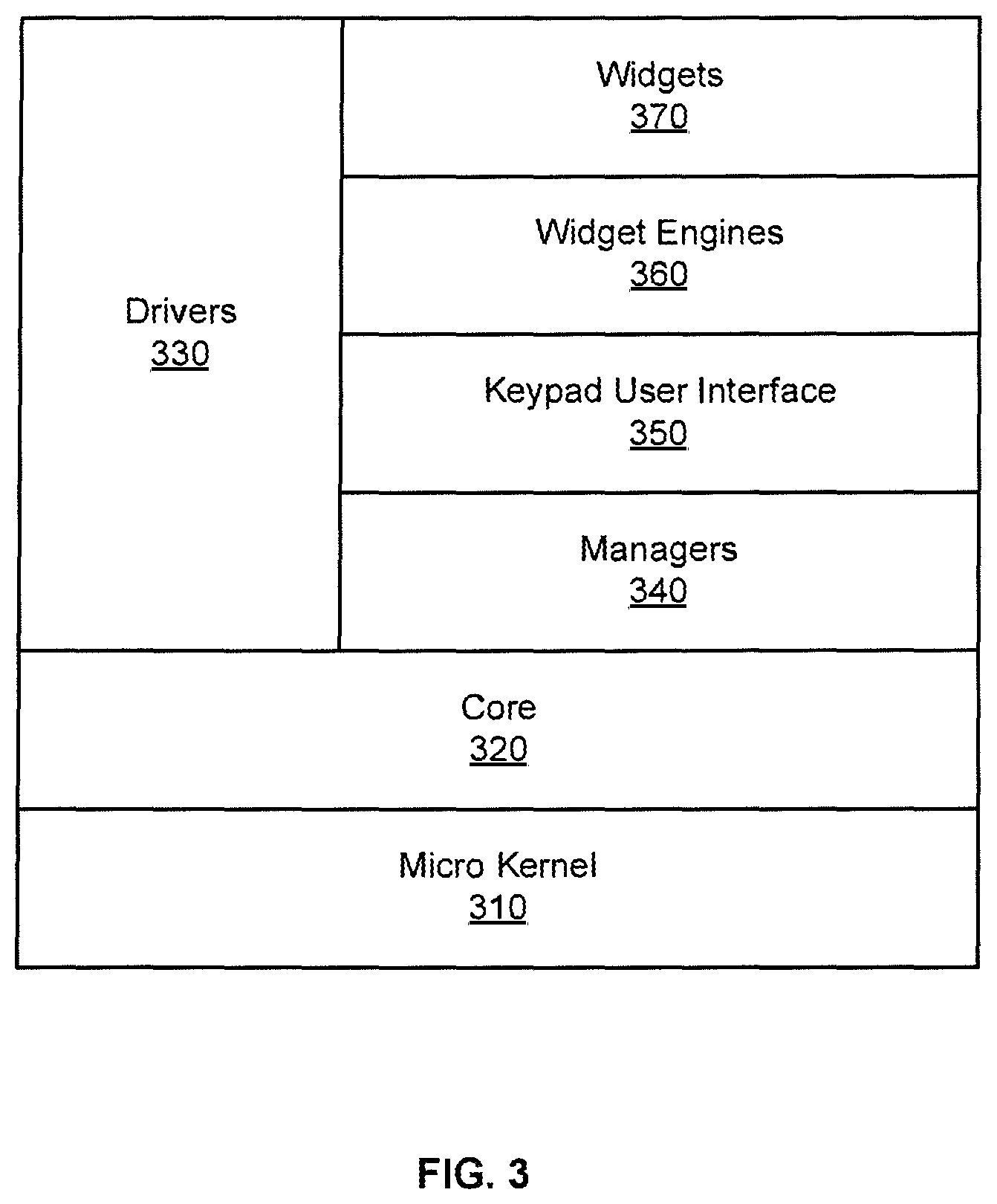
[0011] FIG. 3 is a simplified block diagram illustrating a logical stacking of an SMA controller's firmware architecture, usable with embodiments of the present invention.
[0012] FIG. 4 is an illustration of an example user interface for an SMA controller 120, according to an embodiment of the present invention.
[0013] FIG. 5 is a simplified flow diagram illustrating steps performed in a configuration process of an SMA controller, in accord with embodiments of the present invention.
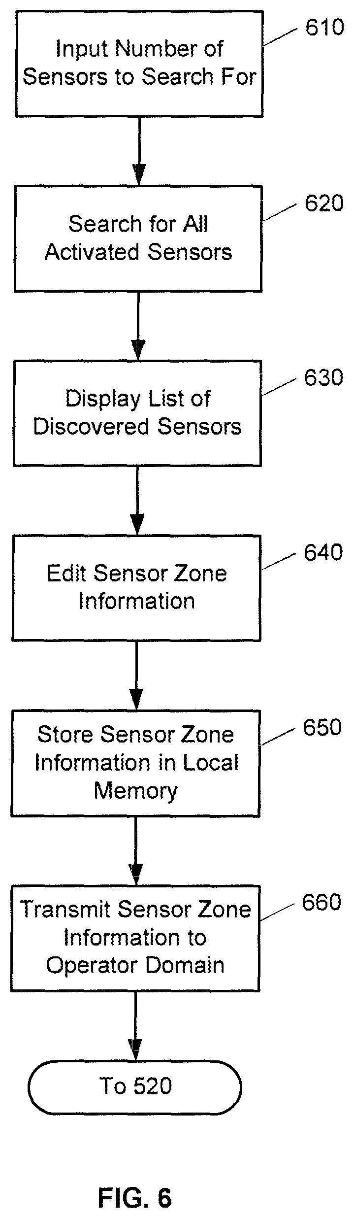
[0014] FIG. 6 is a simplified flow diagram illustrating steps performed in configuring security sensors, in accord with embodiments of the present invention.
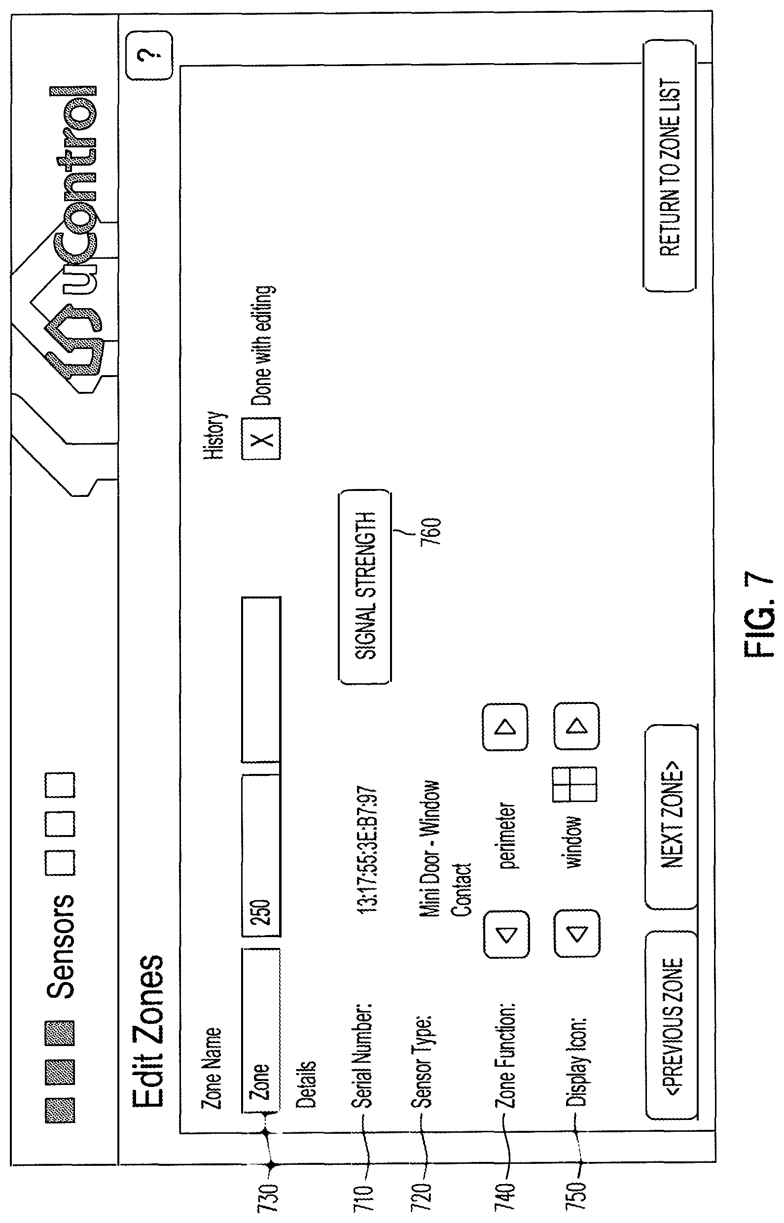
[0015] FIG. 7 is an illustration of a display to permit editing of sensor information (e.g., sensor zone information).
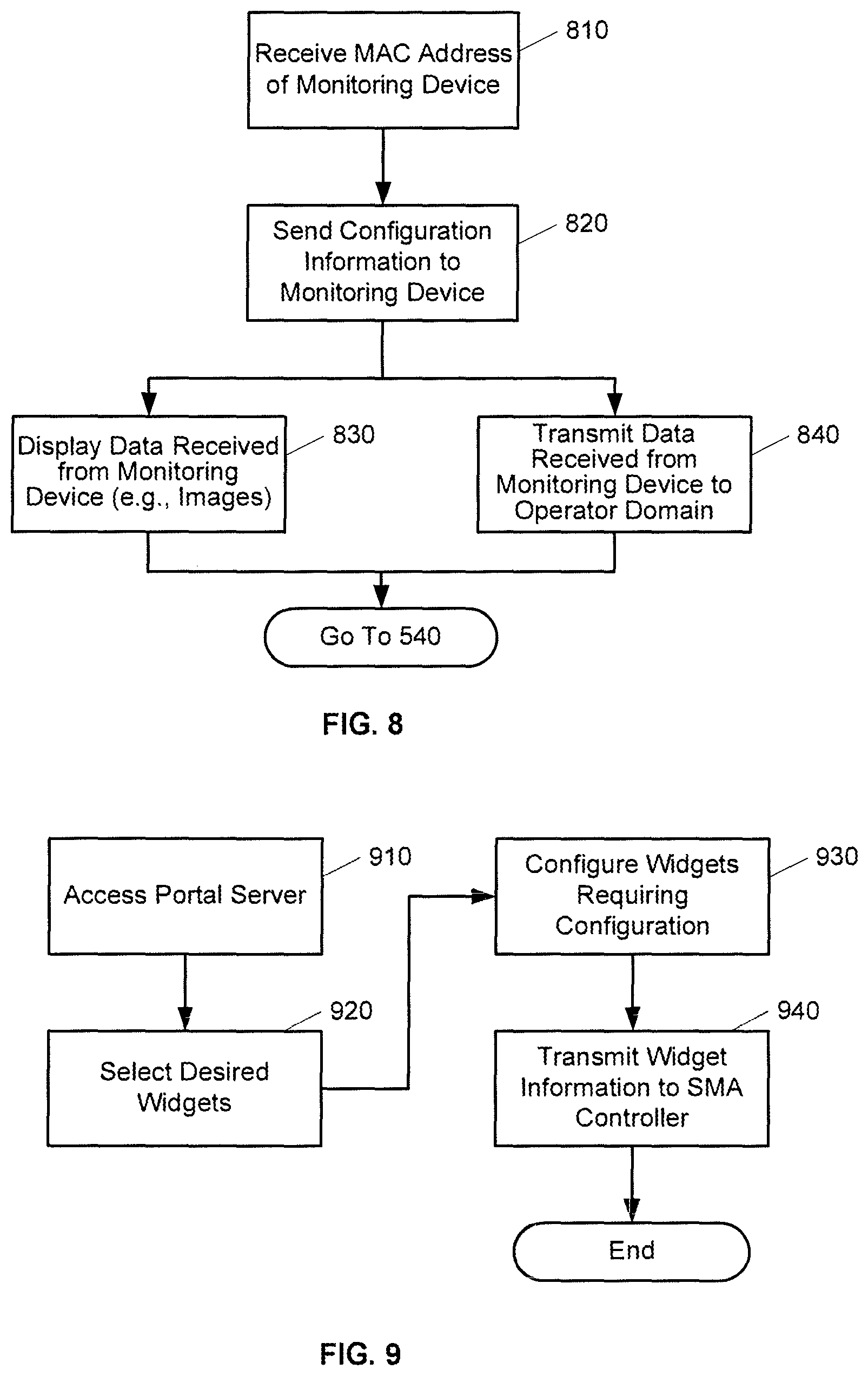
[0016] FIG. 8 is a simplified flow diagram illustrating steps performed to configure a home domain monitoring device, in accord with embodiments of the present invention.
[0017] FIG. 9 is a simplified flow diagram illustrating steps performed in selecting widgets for use by an SMA controller, in accord with embodiments of the present invention.
[0018] FIG. 10 is a simplified flow diagram illustrating an example process for defining rules for a SMA controller, in accord with embodiments of the present invention.
[0019] FIG. 11 is an illustration of an example user interface for entering rules for an SMA controller, in accord with embodiments of the present invention.
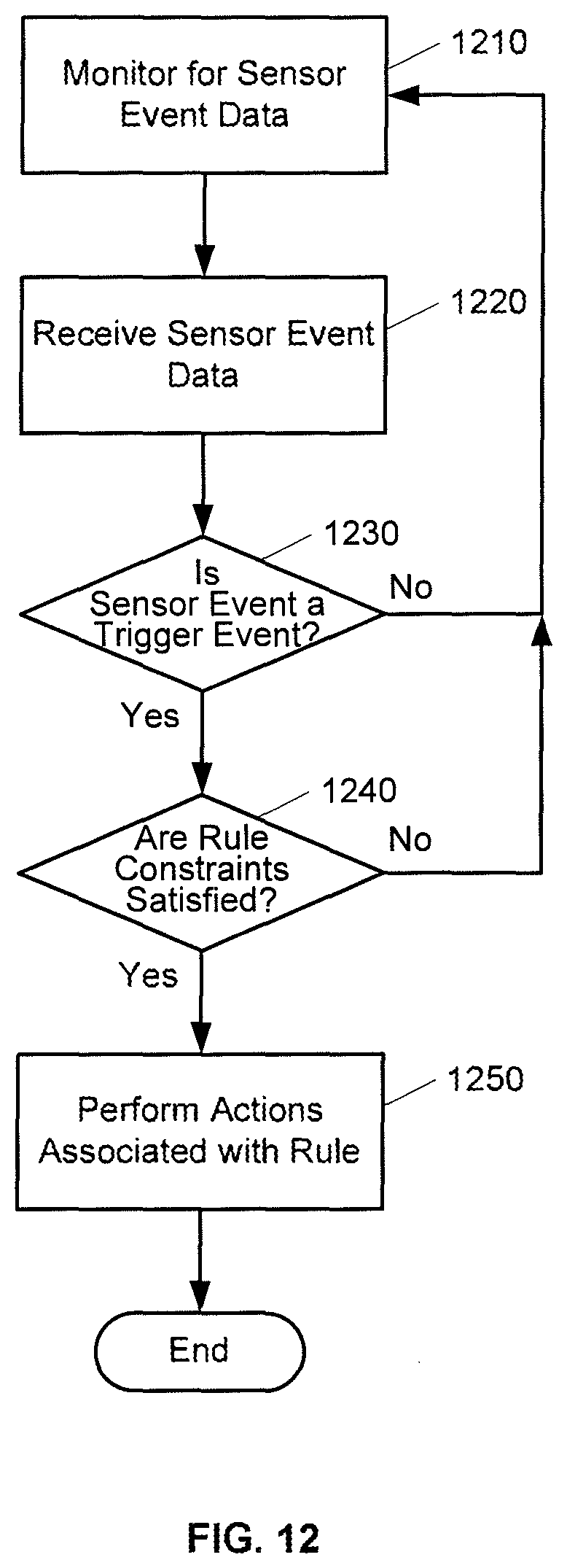
[0020] FIG. 12 is a simplified flow diagram illustrating actions performed in determining an occurrence of a sensor event trigger, in accord with embodiments of the present invention.
[0021] FIG. 13 is a simplified flow diagram illustrating an example of a process for determining whether a negative alert has been triggered, in accord with embodiments of the present invention.
[0022] FIG. 14 depicts a block diagram of a computer system suitable for implementing aspects of the present invention.
[0023] FIG. 15 is a block diagram depicting a network architecture suitable for implementing aspects of the present invention.
DETAILED DESCRIPTION OF ILLUSTRATIVE EMBODIMENTS
[0024] Embodiments of the present invention provide a single platform that provides controller functionality for each of security, monitoring and automation, as well as providing a capacity to function as a bidirectional Internet gateway. Embodiments of the present invention provide such functionality by virtue of a configurable architecture that enables a user to adapt the system for the user's specific needs. Embodiments of the present invention further provide for user configurable rules that associate sensor events with corresponding actions by other sensors, monitoring devices, and automation devices.
Architectural Overview
[0025] Embodiments of the configurable security, monitoring and automation (SMA) controller of the present invention provide not only for communicating with and interpreting signals from sensors and devices within a dwelling, but also for accessing and monitoring those sensors and devices from locations remote to the dwelling. Embodiments of the SMA controller provide such capability through linkages to external servers via access networks such as the Internet, provider network, or a cellular network. The external servers provide a portal environment through which a user can, for example, monitor the state of sensors coupled to the SMA controller in real-time, configure the controller, configure trigger-action rules, and provide controlling information to the SMA controller. The servers can further automatically provide information to a user via remote devices such as mobile phones, computers, and pagers. The servers further provide a connection to a traditional security central station, which can then contact authorities in the event of an alarm condition being detected by the SMA controller in the dwelling.
[0026] FIG. 1 is a simplified block diagram illustrating an architecture including a set of logical domains and functional entities within which embodiments of the present invention interact. A home domain 110 includes an embodiment of the SMA controller 120. The home domain is coupled via an access domain 150 to an operator domain 160 that includes various servers. The servers are in turn coupled to a central station 190 and to various remote user communication options.
[0027] The home domain refers to a collection of security, monitoring and automation entities within a dwelling or other location having SMA devices. SMA controller 120 is a device that provides an end-user SMA interface to the various SMA entities (e.g., radio-frequency sensors) within home domain 110. SMA controller 120 further acts as a gateway interface between home domain 110 and operator domain 160. SMA controller 120 provides such gateway access to operator domain 160 via a network router 125. Network router 125 can be coupled to SMA controller 120 and to home network devices such as home computer 127 via either hard wired or wireless connections. A network router 125 coupled to a broadband modem (e.g., a cable modem or DSL modem) serves as one link to networks in access domain 150.
[0028] SMA devices within home domain 110 can include a variety of RF or wireless sensors 130 whose signals are received and interpreted by SMA controller 120. RF sensors 130 can include, for example, door or window sensors, motion detectors, smoke detectors, glass break detectors, inertial detectors, water detectors, carbon dioxide detectors, light switches, thermostats, key fob devices, and the like. SMA controller 120 can be configured to react to a change in state of any of these detectors. For example, the SMA controller can sound an audio alert upon a detector state change. In addition to acting and reacting to changes in state of RF sensors 130, SMA controller 120 also can be coupled to a legacy security system 135. SMA controller 120 controls the legacy security system by interpreting signals from sensors coupled to the legacy security system and reacting in a user-configured manner. SMA controller 120, for example, will provide alarm or sensor state information from legacy security system 135 to servers in operator domain 160 that may ultimately inform central station 190 to take appropriate action. As will be discussed more fully below, the SMA controller can also be configured to perform a variety of actions in response to a change of state in any sensor.
[0029] SMA controller 120 can also be coupled to one or more monitoring devices 140. Monitoring devices 140 can include, for example, still and video cameras that provide images that are viewable on a screen of SMA controller 120 or a remotely connected device. Monitoring devices 140 can be coupled to SMA controller 120 either wirelessly (e.g., WiFi via router 125) or other connections.
[0030] Home automation devices 145 (e.g., home area network devices having an automation interface) can also be coupled to and controlled by SMA controller 120. SMA controller 120 can be configured to interact with a variety of home automation protocols, such as, for example, Z-Wave and ZigBee.
[0031] Embodiments of SMA controller 120 can be configured to communicate with a variety of RF or wireless sensors and are not limited to the RF sensors, monitoring devices and home automation devices discussed above. A person of ordinary skill in the art will appreciate that embodiments of the present invention are not limited to or by the above-discussed devices and sensors, and can be applied to other areas and devices.
[0032] Embodiments of SMA controller 120 can be used to configure and control home security devices (e.g., 130 and 135), monitoring devices 140 and automation devices 145, either directly or by providing a gateway to remote control via servers in operator domain 160. SMA controller 120 communicates with servers residing in operator domain 160 via networks in access domain 150. Broadband communication can be provided by coupling SMA controller 120 with a network router 125, which in tum is coupled to a wide area network 152, such as a provider network or the Internet, via an appropriate broadband modem. The router can be coupled to the wide area network through cable broadband, DSL, and the like. Wide area network 152, in turn, is coupled to servers in operator domain 160 via an appropriate series of routers and firewalls (not shown). SMA controller 120 can include additional mechanisms to provide a communication with the operator domain. For example, SMA controller 120 can be configured with a cellular network transceiver that permits communication with a cellular network 154. In turn, cellular network 154 can provide access via routers and firewalls to servers in operator domain 160. Embodiments of SMA controller 120 are not limited to providing gateway functionality via cellular and dwelling-based routers and modems. For example, SMA controller 120 can be configured with other network protocol controllers such as WiMAX satellite-based broadband, direct telephone coupling, and the like.
[0033] Operator domain 160 refers to a logical collection of SMA servers and other operator systems in an operator's network that provide end-user interfaces, such as portals accessible to subscribers of the SMA service, that can configure, manage and control SMA elements within home domain 110. Servers in operator domain 160 can be maintained by a provider (operator) of subscriber-based services for SMA operations. Examples of providers include cable providers, telecommunications providers, and the like. A production server architecture in operator domain 160 can support SMA systems in millions of home domains 110.
[0034] Individual server architectures can be of a variety of types, and in one embodiment, the server architecture is a tiered Java2 Enterprise Edition (J2EE) service oriented architecture. Such a tiered service oriented architecture can include an interface tier, a service tier, and a data access logic tier. The interface tier can provide entry points from outside the server processes, including, for example, browser web applications, mobile web applications, web services, HTML, XHTML, SOAP, and the like. A service tier can provide a variety of selectable functionality passed along by the operator to the end user. Service tiers can relate to end user subscription levels offered by the operator (e.g., payment tiers corresponding to "gold" level service, "silver" level service and "bronze" level service). Finally the data access logic tier provides access to various sources of data including database servers.
[0035] FIG. 1 illustrates an example set of servers that can be provided in operator domain 160. Servers 165 can support all non-alarm and alarm events, heartbeat, and command traffic between the various servers and SMA controllers 120. Servers 165 can also manage end-user electronic mail and SMS notification, as well as integration with provider billing, provisioning, inventory, tech support systems, and the like.
[0036] A portal server 170 can provide various user interface applications, including, for example, a subscriber portal, a mobile portal, and a management portal. A subscriber portal is an end-user accessible application that permits an end-user to access a corresponding SMA controller remotely via standard web-based applications. A subscriber portal provides access to the same SMA functions that an interface directly coupled to the SMA controller provides, plus additional functions such as alert and contact management, historical data, widget and camera management, rules management, account management, and the like. A mobile portal can provide all or part of the access available to an end-user via the subscriber portal. A mobile portal can be limited, however, to capabilities of an accessing mobile device (e.g., touch screen or non-touch screen cellular phones). A management portal provides an operator representative access to support and manage SMA controllers in home domains 110 and corresponding user accounts via a web-based application. The management portal can provide tiers of management support so that levels of access to user information can be restricted based on authorization of a particular employee.
[0037] Telephony server 180 can process and send information related to alarm events received from SMA controllers 120 to alarm receivers at central monitoring station 190. A server 165 that processes the alarm event makes a request to telephony server 180 to dial the central station's receiver and send corresponding contact information. Telephony server 180 can communicate with a plurality of central stations 190. Server 165 can determine a correct central station to contact based upon user account settings associated with the transmitting SMA controller. Thus, alarms can be routed to different central stations based upon user accounts. Further, accounts can be transferred from one central station to another by modifying user account information. Telephony server 180 can communicate with alarm receivers at central station 190 using, for example, a security industry standard contact identification protocol (e.g., dual-tone multi-frequency [DTMF]) and broadband protocols.
[0038] A backup server 175 can be provided to guarantee that an alarm path is available in an event that one or more servers 165 become unavailable or inaccessible. A backup server 175 can be co-located to the physical location of servers 165 to address scenarios in which one or more of the servers fail. Alternatively, a backup server 175 can be placed in a location remote from servers 165 in order to address situations in which a network failure or a power failure causes one or more of servers 165 to become unavailable. SMA controllers 120 can be configured to transmit alarm events to a backup server 175 if the SMA controller cannot successfully send such events to servers 165.
[0039] A database server 185 provides storage of all configuration and user information accessible to other servers within operator domain 160. Selection of a type of database provided by database server 185 can be dependent upon a variety of criteria, including, for example, scalability and availability of data. One embodiment of the present invention uses database services provided by an ORACLE database.
[0040] A server 165 in operator domain 160 provides a variety of functionality. Logically, a server 165 can be divided into the following functional modules: a broadband communication module, a cellular communication module, a notification module, a telephony communication module, and an integration module.
[0041] The broadband communication module manages broadband connections and message traffic from a plurality of SMA controllers 110 coupled to server 165. Embodiments of the present invention provide for the broadband channel to be a primary communication channel between an SMA controller 120 and servers 165. The broadband communication module handles a variety of communication, including, for example, all non-alarm and alarm events, broadband heartbeat, and command of traffic between server 165 and SMA controller 120 over the broadband channel. Embodiments of the present invention provide for an always-on persistent TCP socket connection to be maintained between each SMA controller and server 165. A variety of protocols can be used for communications between server 165 and SMA controller 120 (e.g., XML over TCP, and the like). Such communication can be secured using standard transport layer security (TLS) technologies. Through the use of an always-on socket connection, servers 165 can provide near real-time communication between the server and an SMA controller 120. For example, if a user has a subscriber portal active and a zone is tripped within home domain 110, a zone fault will be reflected in near real-time on the subscriber portal user interface.
[0042] The cellular communication module manages cellular connections and message traffic from SMA controllers 120 to a server 165. Embodiments of the present invention use the cellular channel as a backup communication channel to the broadband channel. Thus, if a broadband channel becomes unavailable, communication between an SMA controller and a server switches to the cellular channel. At this time, the cellular communication module on the server handles all non-alarm and alarm events, and command traffic from an SMA controller. When a broadband channel is active, heartbeat messages can be sent periodically on the cellular channel in order to monitor the cellular channel. When a cellular protocol communication stack is being used, a TCP socket connection can be established between the SMA controller and server to ensure reliable message delivery for critical messages (e.g., alarm events and commands). Once critical messages have been exchanged, the TCP connection can be shut down thereby reducing cellular communication costs. As with broadband communication, XMPP can be the messaging protocol used for such communications. Similarly, such communication can be secured using TLS and SASL authentication protocols. Non-critical messages between an SMA controller and a server can be sent using UDP. A compressed binary protocol can be used as a messaging protocol for such communications in order to minimize cellular costs for such message traffic. Such messages can be secured using an encryption algorithm, such as the tiny encryption algorithm (TEA). Cellular communication can be established over two network segments: the GSM service provider's network that provides a path between an SMA controller and a cellular access point, and a VPN tunnel between the access point and an operator domain data center.
[0043] A notification module of server 165 determines if and how a user should be notified of events generated by their corresponding SMA controller 120. A user can specify who to notify of particular events or event types and how to notify the user (e.g., telephone call, electronic mail, text message, page, and the like), and this information is stored by a database server 185. When events such as alarm or non-alarm events are received by a server 165, those events can be past asynchronously to the notification module, which determines if, who and how to send those notifications based upon the user's configuration.
[0044] The telephony communication module provides communication between a server 165 and telephony server 180. When a server 165 receives and performs initial processing of alarm events, the telephony communication module forwards those events to a telephony server 180 which in tum communicates with a central station 190, as discussed above.
[0045] The integration module provides infrastructure and interfaces to integrate a server 165 with operator business systems, such as, for example, billing, provisioning, inventory, tech support, and the like. An integration module can provide a web services interface for upstream integration that operator business systems can call to perform operations like creating and updating accounts and querying information stored in a database served by database server 185. An integration module can also provide an event-driven framework for downstream integration to inform operator business systems of events within the SMA system.
SMA Controller Architecture
[0046] FIG. 2 is a simplified block diagram illustrating a hardware architecture of an SMA controller, according to one embodiment of the present invention. A processor 210 is coupled to a plurality of communications transceivers, interface modules, memory modules, and user interface modules. Processor 210, executing firmware discussed below, performs various tasks related to interpretation of alarm and non-alarm signals received by SMA controller 120, interpreting reactions to those signals in light of configuration information either received from a server (e.g., server 165) or entered into an interface provided by SMA controller 120 (e.g., a touch screen 220). Embodiments of the present invention can use a variety of processors, for example, an ARM core processor such as a FREESCALE i.MX35 multimedia applications processor.
[0047] SMA controller 120 can provide for user input and display via a touch screen 220 coupled to processor 210. Processor 210 can also provide audio feedback to a user via use of an audio processor 225. Embodiments of the present invention can use a variety of audio processors. For example, one embodiment includes a stereo CODEC such as a CIRRUS LOGIC CS42L52 low power stereo CODEC. Audio processor 225 can, in turn, be coupled to one or more speakers that provide sound in home domain 110. As will be discussed more fully below, SMA controller 120 can be configured to provide a variety of sounds for different events detected by sensors and particular zones and other devices associated with the SMA controller. Such sounds can be configured by a user so as to distinguish between different types of events.
[0048] As discussed above, an SMA controller 120 can communicate with a server 165 using different network access means. Processor 210 can provide broadband access to a router (e.g., router 125) via an Ethernet broadband connection PHY 130 or via a WiFi transceiver 235. The router can then be coupled to or be incorporated within an appropriate broadband modem. Cellular network connectivity can be provided by a cellular transceiver 240 that is coupled to processor 210. SMA controller 120 can be configured with a set of rules that govern when processor 210 will switch between a broadband connection and a cellular connection to operator domain 160.
[0049] In order to communicate with the various sensors and devices within home domain 110, processor 210 can be coupled to one or more transceiver modules via, for example, a serial peripheral interface such as a SPI bus 250. Such transceiver modules permit communication with sensors of a variety of protocols in a configurable manner. Embodiments of the present invention can use a transceiver to communicate with a variety of RF sensors 130 using a variety of communication protocols (e.g., ZigBee). Similarly, home automation transceivers (e.g., home area network devices having an automation interface) that communicate using, for example, Z-Wave or ZigBee protocols can be coupled to a processor 210 via SPI 250. If SMA controller 120 is coupled to a legacy security system 135, then a module permitting coupling to the legacy security system can be coupled to processor 210 via SPI 250. Other protocols can be provided for via such plug-in modules including, for example, digital enhanced cordless telecommunication devices (DECT). In this manner, an SMA controller 120 can be configured to provide for control of a variety of devices and protocols known both today and in the future. In addition, processor 210 can be coupled to other types of devices (e.g., transceivers or computers) via a universal serial bus (USB) interface 255.
[0050] In order to locally store configuration information for SMA controller 120, a memory 260 is coupled to processor 210. Additional memory can be coupled to processor 210 via, for example, a secure digital interface 265. A power supply 270 is also coupled to processor 210 and to other devices within SMA controller 120 via, for example, a power management controller module.
[0051] SMA controller 120 is configured to be a customer premises equipment device that works in conjunction with server counterparts in operator domain 160 in order to perform functions required for security monitoring and automation. Embodiments of SMA controller 120 provide a touch screen interface (e.g., 220) into all the SMA features. Via the various modules coupled to processor 210, the SMA controller bridges the sensor network, the control network, and security panel network to broadband and cellular networks. SMA controller 120 further uses the protocols discussed above to carry the alarm and activity events to servers in the operator domain for processing. These connections also carry configuration information, provisioning commands, management and reporting information, security authentication, and any real-time media such as video or audio.
[0052] FIG. 3 is a simplified block diagram illustrating a logical stacking of an SMA controller's firmware architecture, usable with embodiments of the present invention. Since SMA controller 120 provides security functionality for home domain 110, the SMA controller should be a highly available system. High availability suggests that the SMA controller be ready to serve an end-user at all times, both when a user is interacting with the SMA controller through a user interface and when alarms and other non-critical system events occur, regardless of whether a system component has failed. In order to provide such high availability, SMA controller 120 runs a micro-kernel operating system 310. An example of a micro-kernel operating system usable by embodiments of the present invention is a QNX real-time operating system. Under such a micro-kernel operating system, drivers, applications, protocol stacks and file systems run outside the operating system kernel in memory-protected user space. Such a micro-kernel operating system can provide fault resilience through features such as critical process monitoring and adaptive partitioning. As a result, components can fail, including low-level drivers, and automatically restart without affecting other components or the kernel and without requiring a reboot of the system. A critical process monitoring feature can automatically restart failed components because those components function in the user space. An adaptive partitioning feature of the micro kernel operating system provides guarantees of CPU resources for designated components, thereby preventing a component from consuming all CPU resources to the detriment of other system components.
[0053] A core layer 320 of the firmware architecture provides service/event library and client API library components. A client API library can register managers and drivers to handle events and to tell other managers or drivers to perform some action. The service/event library maintains lists of listeners for events that each manager or driver detects and distributes according to one of the lists.
[0054] Driver layer 330 interacts with hardware peripherals of SMA controller 120. For example, drivers can be provided for touch screen 220, broadband connection 230, WiFi transceiver 235, cellular transceiver 240, USB interface 255, SD interface 265, audio processor 225, and the various modules coupled to processor 210 via SPI interface 250. Manager layer 340 provides business and control logic used by the other layers. Managers can be provided for alarm activities, security protocols, keypad functionality, communications functionality, audio functionality, and the like.
[0055] Keypad user interface layer 350 drives the touch screen user interface of SMA controller 120. An example of the touch screen user interface consists of a header and a footer, widget icons and underlying widget user interfaces. Keypad user interface layer 350 drives these user interface elements by providing, for example, management of what the system Arm/Disarm interface button says and battery charge information, widget icon placement in the user face area between the header and footer, and interacting with widget engine layer 360 to display underlying widget user interface when a widget icon is selected.
[0056] In embodiments of the present invention, typical SMA controller functions are represented in the touch screen user interface as widgets (or active icons). Widgets provide access to the various security monitoring and automation control functions of SMA controller 120 as well as providing support for multi-media functionality through widgets that provide, for example, news, sports, weather and digital picture frame functionality. A main user interface screen can provide a set of icons, each of which represents a widget. Selection of a widget icon can then launch the widget. Widget engine layer 360 includes, for example, widget engines for native, HTML and FLASH-based widgets. Widget engines are responsible for displaying particular widgets on the screen. For example, if a widget is developed in HTML, selection of such a widget will cause the HTML widget engine to display the selected widget or touch screen 220. Information related to the various widgets is provided in widget layer 370.
[0057] FIG. 4 is an illustration of an example user interface for an SMA controller 120, according to an embodiment of the present invention. The illustrated user interface provides a set of widget icons 410 that provide access to functionality of SMA controller 120. As illustrated, widgets are provided to access security functionality, camera images, thermostat control, lighting control, and other settings of the SMA controller. Additional widgets are provided to access network-based information such as weather, news, traffic, and digital picture frame functionality. A header 420 provides access to an Arm/Disarm button 425 that allows for arming the security system or disarming it. Additional information can be provided in the header, such as, for example, network status messages. A footer 430 can provide additional status information such as time and date, as displayed.
[0058] A user can select widgets corresponding to desired functionality. Embodiments of the present invention provide for access to widgets via portal server 170. A provider of operator domain 160 can determine functionality accessible to users, either for all users or based upon tiers of users (e.g., subscription levels associated with payment levels). A user can then select from the set of accessible widgets and the selected widgets will be distributed and displayed on the user interface of SMA controller 120. Configurability of SMA controller 120 is also driven by user determined actions and reactions to sensor stimulus.
SMA Controller Configurability
[0059] In accord with embodiments of the present invention, SMA controller 120 can be configured by a user in order to provide desired functionality in home domain 110. In addition to the hardware configurable options discussed above (e.g., modules coupled to SPI interface 250), SMA controller 120 provides for additional configuration through the use of software and/or firmware. For example, SMA controller 120 can be configured to receive signals from a variety of security sensors (e.g., RF sensors 130) and to associate those sensors with the physical environment of home domain 110. In addition, SMA controller 120 can be configured to receive still and video information from one or more cameras, provide a variety of programs and utilities to a user, and is configurable to communicate with a variety of home automation devices.
[0060] FIG. 5 is a simplified flow diagram illustrating steps performed in a configuration process of an SMA controller, in accord with embodiments of the present invention. Embodiments of an SMA controller will typically be configured with security sensor information, either from RF sensors 130 or from a legacy security system 135. Therefore, an SMA controller will be configured to access and interpret information related to those security sensors (510).
[0061] A determination can then be made as to whether or not a user is including security cameras in home domain 110 (520). If cameras are included in the home domain, then a series of steps related to camera configuration is performed (530). Similarly, a determination can be made as to whether or not home automation devices are to be controlled by the SMA controller (540). If so, then a series of steps can be performed to configure the SMA controller to access those home automation devices (550).
[0062] A user can then perform steps necessary to configuring widgets accessible via the SMA controller (560). As discussed above, the user may access a portal server (e.g., 170) to select and configure those widgets that are desirable to be accessed at SMA controller 120.
[0063] Similarly, a user can perform steps necessary to configuring desired rules that will be executed by the SMA controller. As will be discussed more fully below, rules can be provided to define actions the SMA controller will perform in response to various sensor stimuli. The user can access a portal server 170 or the SMA controller directly to configure the rules. Once these configuration steps are performed, the SMA controller can be made available to perform tasks related to securing, monitoring, and providing automation control to home domain 110.
[0064] SMA controller 120 can be configured to receive and interpret signals from a variety of security sensors. Such sensors can include, for example, door/window sensors that can detect opening and closing of a door or window, motion detectors that can detect movement in an area of interest, smoke detectors, glass break detectors, inertia detectors, and key fobs. In order to usefully interpret signals from such detectors, embodiments of SMA controller 120 can search for signals from such sensors and be configured with information related to the location and tasks of those sensors.
[0065] FIG. 6 is a simplified flow diagram illustrating steps performed in configuring security sensors (e.g., 510), in accord with embodiments of the present invention. A user of a security system incorporating SMA controller 120 (e.g., an owner or resident of home domain 110) can decide, based upon the needs within the home domain, the types and number of security sensors needed to secure the home domain. SMA controller 120, via a touch screen input device, for example, can be told how many such sensors to search for (610). The SMA controller can then search for all activated sensors providing a linking message to the SMA controller (620). Such a linking message can provide sensor information including, for example, a unique identification number for the sensor and sensor type information. A touch screen interface for SMA controller 120 can then provide to the user a display indicating information related to all sensors found during the search (630).
[0066] Once presented with information related to all the located sensors, a user can then edit that information to provide specifics as to physical, or zone, location of the sensor within the home domain and other characteristics related to the zone of the sensor (640). For example, a touch screen display 220 coupled to SMA controller 120 can provide a list of all located sensors from which the user can select a specific sensor to define or edit information related to that sensor. The information related to the sensors and zones is then stored in a local memory of the SMA controller 120 (e.g., memory 260) (650). The SMA controller can also transmit the sensor zone information to be stored in a server in operator domain 160 via an available broadband connection (660).
[0067] FIG. 7 is an illustration of a display that can be provided by embodiments of the present invention to permit editing of sensor information (e.g., sensor zone information). As illustrated, the display can provide information such as the unique identifier of the sensor (serial number 710) and the sensor type (sensor type 720). As indicated above, unique identifier and sensor type information is provided by the sensor during the search and location process. Through a display such as that illustrated in FIG. 7, a user can define additional zone characteristics related to the sensor. For example, a user can define or select a zone name 730 to associate with the sensor. Such a zone name can be entered by a user through the use of a touch screen-based keyboard or selected from a list of common names displayed on the touch screen.
[0068] A zone function 740 can also be provided to be associated with the sensor. A zone function determines behavior of the zone and is dependent on the zone type. For example, a door/window sensor can function as an entry/exit zone or as a perimeter zone. Each zone type can have one or more configurable zone functions. For example, a motion detector can have a zone function of interior follower, a smoke/heat detector can have a zone function of 24-hour fire monitoring, a glass break detector can have a zone function of a perimeter zone, and an inertia detector can have an entry/exit zone function or a perimeter zone function.
[0069] Selection of a zone function definition alters how the security system acts and reacts to signals received from a sensor in that zone. The following table illustrates examples of zone functions and their associated action/reaction definitions.
TABLE-US-00001 TABLE 1 Zone Function Definition Entry/Exit Allow exiting the home domain when the system is arming and will begin an entry delay when opened if the system is armed. Zone can be bypassed and can have specific tones assigned for open and close events. Perimeter Generate an alarm immediately if tripped while the system is armed. Can be bypassed and can have specific tones assigned for open and close events. Interior Follower Protect the internal spaces of the home domain and trigger an immediate alarm if the system is armed in away mode. Zone is not armed when the system is in armed stay mode. Can be bypassed and can have specific activity/non activity tones assigned. 24-Hour Fire Generate an immediate fire alarm if triggered. Zone cannot be bypassed. 24-Hour Monitor Generate notifications in the home and will beep the keypad but will not sound the full alarm. Can be bypassed. 24-Hour Environmental Generates notifications, beeps keypads, and sounds the siren to Jet people within the home domain know to evacuate the premises. Cannot be bypassed. 24-Hour Inform Will never generate an alarm, even if the system is armed. Upon triggering of the sensor will make the configured sound and send events to the operator domain. Can be bypassed.
[0070] By defining such zones, a user can control how the security functions of SMA controller 120 react to various sensor triggers.
[0071] A user can also configure a display icon 750 associated with the sensor zone. In many cases, the available icons will be limited to one type of icon that graphically relates to the sensor type. But, for example, with a door/window sensor, icons can be made available that illustrate a door or a window as appropriate. FIG. 7 further illustrates a signal strength button 760 that, when selected, can illustrate strength of the signal between the wireless hub located within SMA controller 120 and the associated sensor.
[0072] The sensor zone information entered through the use of a display such as that illustrated in FIG. 7, can be stored in local data tables that are stored in memory 260 of SMA controller 120 (650). In addition, sensor zone information can also be transmitted via access domain 150 to servers in operator domain 160 for storage and other configuration tasks (e.g., database server 185) (660). By storing the sensor zone information in servers in the operator domain, the information is available to a user accessing a portal server 170. A user could then edit the sensor zone information through use of the portal rather than the SMA controller interface. Further, sensor zone information stored on database server 185 is retained even if an SMA controller suffers from an event that makes the SMA controller unusable. In such an event, a new SMA controller can be installed in home domain 110 and the information stored in operator domain 160 can be provided to the new SMA controller. This eliminates a need to manually reconfigure the new SMA controller with all sensor information.
[0073] FIG. 8 is a simplified flow diagram illustrating steps performed to configure a home domain monitoring device, in accord with embodiments of the present invention. As discussed above, SMA controller 120 can communicate with home domain monitoring devices 140, such as cameras and audio monitors. For example, a wireless camera can be activated and can communicate with SMA controller 120 via a router 125. During configuration, the SMA controller can detect the presence of a camera by receiving an MAC address of the camera from the router (810). The SMA controller can then configure the camera to communicate wirelessly with the router and the SMA controller (820). The SMA controller can pass a variety of information to the camera during a configuration phase, including, for example, an administrative user name and password, camera name, camera description, time zone, current time, language, user session name and password for list of users allowed to access the camera, network settings such as IP address and name servers, protocol settings, motion detection settings, and desired camera image settings such as resolution and video adjustments. In addition, the camera can provide information to the SMA controller for storage, such as, for example, device type, manufacturer, model number, and other control information.
[0074] Once the SMA controller and camera are configured, then images generated by the camera can be displayed on a display device associated with SMA controller 120 (830) or can be communicated to a portal server in operator domain 160 via a network in access domain 150 for display on a computer or mobile devices communicating with the portal server (840). SMA controller 120 can also store information related to the camera, such as, for example, a camera name, location of the camera, and relationship of the camera with a defined sensor zone. Embodiments of the present invention can provide both still and video images either on the SMA controller display or a portal display. An SMA controller can be configured to communicate with more than one monitoring device.
[0075] SMA controller 120 also has a capability of providing access to a variety of functionality through the use of widget programs. FIG. 4, discussed above, illustrates an example of a home screen display of SMA controller 120, showing a set of icons having associated widget programs (410). Some of the widgets provide for SMA controller functionality, such as, for example, security access, camera monitoring, and setting modification. Additionally, widgets can be provided to access SMA controller automation functionality such as thermostat control and lighting control. In addition, an SMA controller can provide display of user-selectable widgets (e.g., calendar, weather, news, traffic, and photos).
[0076] FIG. 9 is a simplified flow diagram illustrating steps performed in selecting widgets for use by an SMA controller, in accord with embodiments of the present invention. A user can select those user selectable widget programs that are desired by accessing a portal server 170 (910). The user can view those widget programs that are available to the user and select those that the user wishes to install on the SMA controller (920). A user can also configure how the widget icons are displayed on the home screen (e.g., position of each icon) as well as provide any individual widget configuration information (e.g., zip code information for weather and traffic widgets) (930). Depending upon the purpose of a widget, a user may have a variety of options in configuring that widget.
[0077] By making widgets available on a portal server in the operator domain, the operator can control the nature and types of widgets available to a user. For example, an operator can define a series of option tiers for their users, with each tier having increasing numbers of available widgets or different type of widget functionality. Further, by making the widgets available through the portal, an operator can control the quality of the available widgets and ensuring that widgets will not affect the operability of SMA controller under the operator's control.
[0078] Once selected, code related to the widgets and widget setup information is transferred from servers in operator domain 160 to the associated SMA controller 120 in home domain 110 (940). That code information is stored in SMA controller 120, for example, in memory 260.
[0079] SMA controller 120 can also be configured to provide home automation functionality. As discussed above, a variety of hardware modules can be coupled to the SMA controller, allowing the SMA controller to communicate using protocols associated with those modules. In addition to the hardware configurability, SMA controller 120 is configured to communicate with a variety of devices selected to be controlled by the SMA controller. In a manner similar to that discussed above with regard to configuration of security sensors, SMA controller 120 is configured to detect available automated devices and display information regarding those devices. A user can then edit information about those devices and behavior of those devices through, for example, a touch screen interface coupled to SMA controller 120. In addition, a user can provide automation commands via accessing portal server 170 to modify those settings, take immediate control of an automated device, or provide rules for activation of the devices in response to sensor stimulus. Similarly, a user can take immediate control of automated devices from the touch screen of the SMA controller (e.g., through use of widgets such as "lights" and "thermostat," illustrated in FIG. 4). Configuration information related to the automated devices can be stored in a memory of SMA controller 120 or in a server located in operator domain 160.
[0080] In this manner, embodiments of the present invention provide configurable control over a variety of SMA devices in the home domain using a single controller. A variety of different device protocols can be provided for through the use of plug-in modules. Further flexibility is provided through configurable set up and control of security and automation devices. Additional functionality is provided through the use of user-selectable and user-configurable widgets.
Configuration and Execution of Trigger-Action Rules
[0081] The unique consolidation of monitoring and control of security sensors, monitoring devices and home area network devices having an automation interface ("automation devices") by a single centralized controller, as with embodiments of the present invention, enables configuration of the controller to perform actions in response to sensor stimuli (e.g., security sensor events or automation device events). In such an environment, an end-user can define rules that, for example, cause automation devices to perform actions in response to a sensor trigger event. Further, since sensor zone configuration information is provided to servers in the operator domain, a subscriber portal can be configured to allow an end-user subscriber to define the rules using a server supported user interface, and then provide those rules to the SMA controller. Similarly, the rules can be defined directly on an SMA controller with a version of those rules being stored in an appropriate location in the operator domain.
[0082] FIG. 10 is a simplified flow diagram illustrating an example process for defining rules for a SMA controller, in accord with embodiments of the present invention. The steps illustrated in FIG. 10 can be performed either through a portal server located in operator domain 160 (e.g., portal server 170) or directly on an SMA controller 120 through an associated input device (e.g., a touch screen).
[0083] Since the rules being discussed are triggered by a sensor event, a sensor is selected to be associated with a rule being defined (1010). As is illustrated in FIG. 11 of an example user interface, a list of available sensor devices to be associated with the rule is presented (1110). Sensor device list 1110 can be populated from the associated SMA controller's zone configuration information or from home automation device information. As discussed above, an SMA controller both stores the sensor zone configuration information locally and in a server within operator domain 160. Therefore, the sensor zone configuration information is available to both the SMA controller and the portal server.
[0084] Once a sensor is selected, a sensor event can be selected that triggers the rule ( 1020). As is illustrated in FIG. 11, a list of available sensor trigger events is populated in accord with the type of sensor selected to be associated with the rule (1120). As is illustrated in the example of FIG. 11, a back door sensor can have a state of either being closed or open. As discussed above, when sensor devices are detected by an SMA controller, sensor type information is provided to the SMA controller by the sensor. This sensor type information can be used to determine available sensor events to trigger a rule. For example, a data structure containing associations of sensor type with sensor events can be referenced by the rule configuration process upon selection of a sensor device to be associated with a rule. The available sensor events can then be used to populate the list in the user interface.
[0085] Once a sensor and a sensor event have been selected, an action desired to be performed in response to the trigger event is provided (1030). A list of available actions that is in accord with available "output" devices known to the SMA controller can be provided. An "output" device can be any device accessible to the SMA controller that can perform a function in response to a command from the SMA controller. "Output" devices can include, for example, piezo speakers, sirens, lights, monitoring devices such as cameras, and thermostats. Alternatively, the SMA controller can be configured to send a text message or an email or another form of communication to an end-user, informing the end-user of the trigger event.
[0086] FIG. 11 illustrates an example of a selection list of desirable actions (1130) that is populated in accord with available output devices to the associated SMA controller. Such a list becomes available at a portal server due to the provision of configuration information by the SMA controller to servers in the operator domain. In addition, certain actions can result in display of a list of secondary actions specifying a particular response. For example, FIG. 11 illustrates a variety of sounds available to be emitted by a piezo speaker associated with an SMA controller (1135). Other types of secondary actions can include, for example, an email address along with desired text, a mobile phone number along with desired text for text messages, identification of a specific light to tum on, identification of a specific camera with which to take a picture, and the like. These lists are populated in accord with the selected action and devices capable of performing the selected action.
[0087] A configured rule can also have accompanying constraints (1040). As illustrated in FIG. 11, constraints can include limitations of time when the rules should be executed or not executed (1140). In addition, negative constraints can be provided which cause a rule to be executed if a specified event does not occur during a specified period of time. Another type of constraint can include, for example, defining whether the rule is executed in light of an arm/disarm state of the SMA controller (1145). It should be noted that the constraints discussed above are provided by nature of an example and are not intended to be a limiting or exhaustive set of constraints within which the rules-based environment of the present invention can operate.
[0088] Once a rule has been defined, an identifier can be associated with the rule (1050 and 1150). Using such an identifier, a user can subsequently select rules to be enabled or disabled or deleted or otherwise modified.
[0089] In one embodiment of the present invention, the parameters of defined rules can be stored in a tag-based file such as an XML file defined by an XML schema definition (XSD). As rules are input either on the SMA controller or a portal server, the XML rules file can be constructed in light of the XSD. Once the rules file has been completed, the XML rules file can be transmitted from the server in the operator domain to the associated SMA controller. Similarly, if the rules file is being constructed on the SMA controller, the XML rules file can be provided to a server in the operator domain for storage therein. The XML rules file can then be used by the SMA controller as a reference for event triggers during operation of the SMA controller.
[0090] FIG. 12 is a simplified flow diagram illustrating actions performed in determining an occurrence of a sensor event trigger, in accord with embodiments of the present invention. A SMA controller monitors all associated sensor devices for sensor event data (e.g., a sensor fault) (1210). When the SMA controller receives sensor event data (1220), a determination is made as to whether the sensor event is a rule trigger event (1230). Such a determination can be made by examining the identification of the sensor device detecting the event and identification of the event that occurred and comparing that information to corresponding fields in the rules definition file. If the sensor event is not a trigger event, then the SMA controller returns to monitoring for sensor event data. If the sensor event is a trigger event, then a determination is made as to whether all constraints associated with the trigger event are satisfied (1240). For example, if there is a specified time range within which a particular rule is constrained for response, or if the SMA controller is armed or disarmed. If the constraints associated with the trigger event are not satisfied, then the SMA controller continues to monitor for further sensor event data. If the constraints associated with the trigger event are satisfied, then the actions defined in the rule are performed by the SMA controller (1250).
[0091] In this manner, the SMA controller can be configured to perform a variety of sensor driven home automation tasks. For example, thermostats in the house can be adjusted in accord with a person entering the house. As another example, if a motion sensor is triggered, the SMA controller can cause a nearby camera monitoring device to take a picture and send that picture to the end-user by a multimedia text message or an email. As another example, the system can be configured to send a text message to the end-user if the system detects a door opening between 3:00 p.m. and 3:30 p.m. thereby indicating that the user's children are now at home. As can be seen, significant flexibility is available to a user in configuring rules that enhance the user's lifestyle. This flexibility is limited only by the devices available to the SMA controller.
[0092] FIG. 13 is a simplified flow diagram illustrating an example of a process for determining whether a negative alert has been triggered, in accord with embodiments of the present invention. As discussed above, a negative alert occurs when a specified sensor event does not occur within a specified period. The SMA controller monitors the configured rules for a stated start time (1310). At the start time, the SMA controller resets a state tracking variable associated with sensor specified in the rule (1320). If an event does occur with the specified sensor (1330), then the state tracking variable associated with the sensor is changed to reflect that state change (1340).
[0093] At the rule's specified end time, the value of the state tracking variable associated with the sensor is checked (1350). If the state variable changed (1360), then no negative alert is necessary since the specified sensor event did occur. The SMA controller can return to monitoring for another rule start time. If the state variable did not change during the specified period, then the actions associated with the negative alert rule are performed by the SMA controller (1370). Once the negative alert actions have been performed, then the SMA controller can return to monitoring for relevant start times associated with negative alert rules.
[0094] Through the use of negative alert rules, a user can utilize the SMA controller to inform the user of when something that should happen within a specified period does not happen. For example, a negative alert rule can be set up to inform a user if the front door does not open between 3:00 p.m. and 3:30 p.m. Such a rule can be used, for example, to inform a user when their children do not arrive at home by an expected time. Again, negative alert rules provide a user flexibility to enhance their lifestyle and security and are limited only by the sensors and devices associated with that user's SMA controller.
[0095] The rules definitions and implementations provided by embodiments of the present invention are enhanced by the all-in-one nature of combining security, monitoring and automation control in one centralized unit. Rules configuration is further enhanced by the communicative coupling between the SMA controller and servers in the operator domain, which allows for detailed information regarding sensor devices as well as automation devices known to servers in the operator domain.
An Example Computing And Network Environment
[0096] As shown above, the present invention can be implemented using a variety of computer systems and networks. An example of one such computing and network environment is described below with reference to FIGS. 14 and 15.
[0097] FIG. 14 depicts a block diagram of a computer system 1410 suitable for implementing aspects of the present invention (e.g., servers 165, portal server 170, backup server 175, telephony server 180, and database server 185). Computer system 1410 includes a bus 1412 which interconnects major subsystems of computer system 1410, such as a central processor 1414, a system memory 1417 (typically RAM, but which may also include ROM, flash RAM, or the like), an input/output controller 1418, an external audio device, such as a speaker system 1420 via an audio output interface 1422, an external device, such as a display screen 1424 via display adapter 1426, serial ports 1428 and 1430, a keyboard 1432 (interfaced with a keyboard controller 1433), a storage interface 1434, a floppy disk drive 1437 operative to receive a floppy disk 1438, a host bus adapter (HBA) interface card 1435A operative to connect with a Fibre Channel network 1490, a host bus adapter (HBA) interface card 1435B operative to connect to a SCSI bus 1439, and an optical disk drive 1440 operative to receive an optical disk 1442. Also included are a mouse 1446 (or other point-and-click device, coupled to bus 1412 via serial port 1428), a modem 1447 (coupled to bus 1412 via serial port 1430), and a network interface 1448 (coupled directly to bus 1412).
[0098] Bus 1412 allows data communication between central processor 1414 and system memory 1417, which may include read-only memory (ROM) or flash memory (neither shown), and random access memory (RAM) (not shown), as previously noted. The RAM is generally the main memory into which the operating system and application programs are loaded. The ROM or flash memory can contain, among other code, the Basic Input-Output system (BIOS) which controls basic hardware operation such as the interaction with peripheral components. Applications resident with computer system 1410 are generally stored on and accessed via a computer-readable medium, such as a hard disk drive (e.g., fixed disk 1444), an optical drive (e.g., optical drive 1440), a floppy disk unit 1437, or other storage medium. Additionally, applications can be in the form of electronic signals modulated in accordance with the application and data communication technology when accessed via network modern 1447 or interface 1448.
[0099] Storage interface 1434, as with the other storage interfaces of computer system 1410, can connect to a standard computer-readable medium for storage and/or retrieval of information, such as a fixed disk drive 1444. Fixed disk drive 1444 may be a part of computer system 1410 or may be separate and accessed through other interface systems. Modern 1447 may provide a direct connection to a remote server via a telephone link or to the Internet via an internet service provider (ISP). Network interface 1448 may provide a direct connection to a remote server via a direct network link to the Internet via a POP (point of presence). Network interface 1448 may provide such connection using wireless techniques, including digital cellular telephone connection, Cellular Digital Packet Data (CDPD) connection, digital satellite data connection or the like.
[0100] Many other devices or subsystems (not shown) may be connected in a similar manner (e.g., document scanners, digital cameras and so on). Conversely, all of the devices shown in FIG. 14 need not be present to practice the present invention. The devices and subsystems can be interconnected in different ways from that shown in FIG. 14. The operation of a computer system such as that shown in FIG. 14 is readily known in the art and is not discussed in detail in this application. Code to implement the present invention can be stored in computer-readable storage media such as one or more of system memory 1417, fixed disk 1444, optical disk 1442, or floppy disk 1438. The operating system provided on computer system 1410 may be MS-DOS.RTM., MS-WINDOWS.RTM., OS/2.RTM., UNIX.RTM., Linux.RTM., or another known operating system.
[0101] Moreover, regarding the signals described herein, those skilled in the art will recognize that a signal can be directly transmitted from a first block to a second block, or a signal can be modified (e.g., amplified, attenuated, delayed, latched, buffered, inverted, filtered, or otherwise modified) between the blocks. Although the signals of the above described embodiment are characterized as transmitted from one block to the next, other embodiments of the present invention may include modified signals in place of such directly transmitted signals as long as the informational and/or functional aspect of the signal is transmitted between blocks. To some extent, a signal input at a second block can be conceptualized as a second signal derived from a first signal output from a first block due to physical limitations of the circuitry involved (e.g., there will inevitably be some attenuation and delay). Therefore, as used herein, a second signal derived from a first signal includes the first signal or any modifications to the first signal, whether due to circuit limitations or due to passage through other circuit elements which do not change the informational and/or final functional aspect of the first signal.
[0102] FIG. 15 is a block diagram depicting a network architecture 1500 in which client systems 1510, 1520 and 1530, as well as storage servers 1540A and 1540B (any of which can be implemented using computer system 1410), are coupled to a network 1550. Storage server 1540A is further depicted as having storage devices 1560A(1)-(N) directly attached, and storage server 1540B is depicted with storage devices 1560B(1)-(N) directly attached. Storage servers 1540A and 1540B are also connected to a SAN fabric 1570, although connection to a storage area network is not required for operation of the invention. SAN fabric 1570 supports access to storage devices 1580(1)-(N) by storage servers 1540A and 1540B, and so by client systems 1510, 1520 and 1530 via network 1550. Intelligent storage array 1590 is also shown as an example of a specific storage device accessible via SAN fabric 1570.
[0103] With reference to computer system 1410, modem 1447, network interface 1448 or some other method can be used to provide connectivity from each of client computer systems 1510, 1520 and 1530 to network 1550. Client systems 1510, 1520 and 1530 are able to access information on storage server 1540A or 1540B using, for example, a web browser or other client software (not shown). Such a client allows client systems 1510, 1520 and 1530 to access data hosted by storage server 1540A or 1540B or one of storage devices 1560A(1)-(N), 1560B(1)-(N), 1580(1)-(N) or intelligent storage array 1590. FIG. 15 depicts the use of a network such as the Internet for exchanging data, but the present invention is not limited to the Internet or any particular network-based environment.
Other Embodiments
[0104] The present invention is well adapted to attain the advantages mentioned as well as others inherent therein. While the present invention has been depicted, described, and is defined by reference to particular embodiments of the invention, such references do not imply a limitation on the invention, and no such limitation is to be inferred. The invention is capable of considerable modification, alteration, and equivalents in form and function, as will occur to those ordinarily skilled in the pertinent arts. The depicted and described embodiments are examples only, and are not exhaustive of the scope of the invention.
[0105] The foregoing describes embodiments including components contained within other components (e.g., the various elements shown as components of computer system 1410). Such architectures are merely examples, and, in fact, many other architectures can be implemented which achieve the same functionality. In an abstract but still definite sense, any arrangement of components to achieve the same functionality is effectively "associated" such that the desired functionality is achieved. Hence, any two components herein combined to achieve a particular functionality can be seen as "associated with" each other such that the desired functionality is achieved, irrespective of architectures or intermediate components. Likewise, any two components so associated can also be viewed as being "operably connected," or "operably coupled," to each other to achieve the desired functionality.
[0106] The foregoing detailed description has set forth various embodiments of the present invention via the use of block diagrams, flowcharts, and examples. It will be understood by those within the art that each block diagram component, flowchart step, operation and/or component illustrated by the use of examples can be implemented, individually and/or collectively, by a wide range of hardware, software, firmware, or any combination thereof. For example, specific electronic components can be employed in an application specific integrated circuit or similar or related circuitry for implementing the functions associated with one or more of the described functional blocks.
[0107] The present invention has been described in the context of fully functional computer systems; however, those skilled in the art will appreciate that the present invention is capable of being distributed as a program product in a variety of forms, and that the present invention applies equally regardless of the particular type of computer-readable media used to actually carry out the distribution. Examples of computer-readable media include computer-readable storage media, as well as media storage and distribution systems developed in the future.
[0108] The above-discussed embodiments can be implemented by software modules that perform one or more tasks associated with the embodiments. The software modules discussed herein may include script, batch, or other executable files. The software modules may be stored on a machine-readable or computer-readable storage media such as magnetic floppy disks, hard disks, semiconductor memory (e.g., RAM, ROM, and flash-type media), optical discs (e.g., CD-ROMs, CD-Rs, and DVDs), or other types of memory modules. A storage device used for storing firmware or hardware modules in accordance with an embodiment of the invention can also include a semiconductor-based memory, which may be permanently, removably or remotely coupled to a microprocessor/memory system. Thus, the modules can be stored within a computer system memory to configure the computer system to perform the functions of the module. Other new and various types of computer-readable storage media may be used to store the modules discussed herein.
[0109] The above description is intended to be illustrative of the invention and should not be taken to be limiting. Other embodiments within the scope of the present invention are possible. Those skilled in the art will readily implement the steps necessary to provide the structures and the methods disclosed herein, and will understand that the process parameters and sequence of steps are given by way of example only and can be varied to achieve the desired structure as well as modifications that are within the scope of the invention. Variations and modifications of the embodiments disclosed herein can be made based on the description set forth herein, without departing from the scope of the invention.
[0110] Consequently, the invention is intended to be limited only by the scope of the appended claims, giving full cognizance to equivalents in all respects.
* * * * *
D00000
D00001
D00002
D00003
D00004
D00005
D00006
D00007
D00008
D00009
D00010
D00011
D00012

D00013
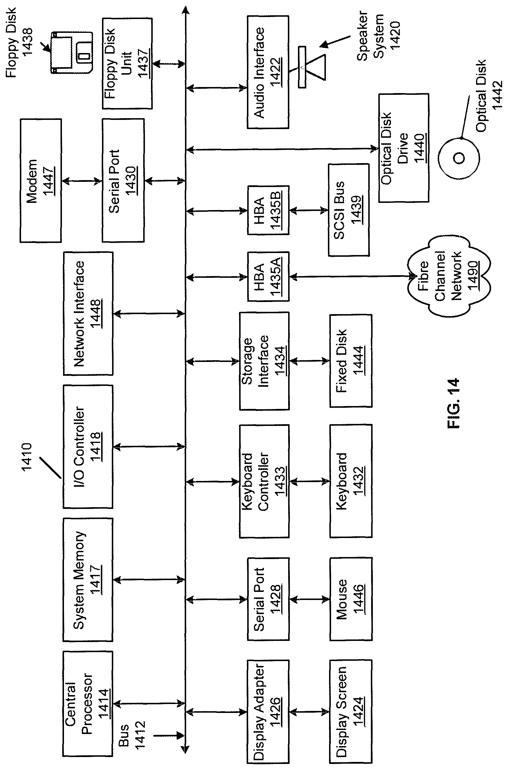
D00014
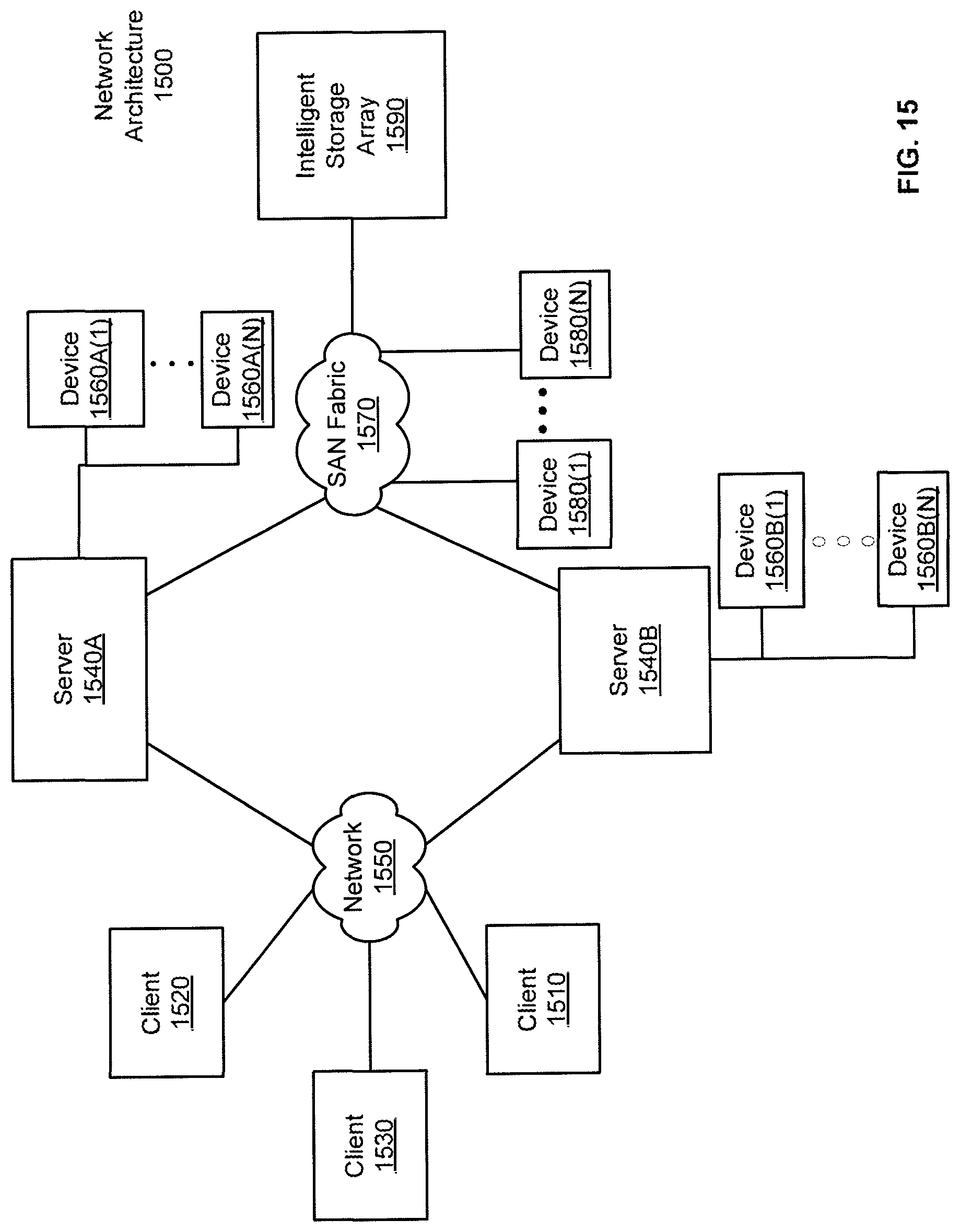
XML
uspto.report is an independent third-party trademark research tool that is not affiliated, endorsed, or sponsored by the United States Patent and Trademark Office (USPTO) or any other governmental organization. The information provided by uspto.report is based on publicly available data at the time of writing and is intended for informational purposes only.
While we strive to provide accurate and up-to-date information, we do not guarantee the accuracy, completeness, reliability, or suitability of the information displayed on this site. The use of this site is at your own risk. Any reliance you place on such information is therefore strictly at your own risk.
All official trademark data, including owner information, should be verified by visiting the official USPTO website at www.uspto.gov. This site is not intended to replace professional legal advice and should not be used as a substitute for consulting with a legal professional who is knowledgeable about trademark law.