Method and Apparatus for Modulating Haptic Feedback
Long; Benjamin John Oliver ; et al.
U.S. patent application number 17/645305 was filed with the patent office on 2022-04-14 for method and apparatus for modulating haptic feedback. The applicant listed for this patent is Ultrahaptics IP Ltd. Invention is credited to Thomas Andrew Carter, Benjamin John Oliver Long, Sriram Subramanian.
| Application Number | 20220113806 17/645305 |
| Document ID | / |
| Family ID | |
| Filed Date | 2022-04-14 |


| United States Patent Application | 20220113806 |
| Kind Code | A1 |
| Long; Benjamin John Oliver ; et al. | April 14, 2022 |
Method and Apparatus for Modulating Haptic Feedback
Abstract
The present invention concerns a method and apparatus for the modulation of an acoustic field for providing tactile sensations. A method of creating haptic feedback using ultrasound is provided. The method comprises the steps of generating a plurality of ultrasound waves with a common focal point using a phased array of ultrasound transducers, the common focal point being a haptic feedback point, and modulating the generation of the ultrasound waves using a waveform selected to produce little or no audible sound at the haptic feedback point.
| Inventors: | Long; Benjamin John Oliver; (Bristol, GB) ; Carter; Thomas Andrew; (Bristol, GB) ; Subramanian; Sriram; (Bristol, GB) | ||||||||||
| Applicant: |
|
||||||||||
|---|---|---|---|---|---|---|---|---|---|---|---|
| Appl. No.: | 17/645305 | ||||||||||
| Filed: | December 20, 2021 |
Related U.S. Patent Documents
| Application Number | Filing Date | Patent Number | ||
|---|---|---|---|---|
| 16600500 | Oct 13, 2019 | 11204644 | ||
| 17645305 | ||||
| 15966213 | Apr 30, 2018 | 10444842 | ||
| 16600500 | ||||
| 14916179 | Mar 2, 2016 | 9958943 | ||
| PCT/GB2015/052578 | Sep 7, 2015 | |||
| 15966213 | ||||
| International Class: | G06F 3/01 20060101 G06F003/01; G08B 6/00 20060101 G08B006/00 |
Foreign Application Data
| Date | Code | Application Number |
|---|---|---|
| Sep 9, 2014 | GB | 1415923.0 |
Claims
1-24. (canceled)
25. A method comprising: creating a pressure pattern with a plurality of transducers using ultrasound, comprising: 1) offsetting a first transducer of the plurality of transducers for a position, phase, and amplitude of each of the plurality of transducers other than the first transducer to produce an instance of iterative transducer offset data; and 2) determining a phase and an amplitude of a point within a model volume by combining instances of iterative transducer offset data.
26. The method as in claim 25, wherein offsetting the first transducer for the phase and amplitude of each of the plurality of transducers other than the first transducer involves interpolation.
27. The method as in claim 26, wherein the interpolation is a linear interpolation.
28. The method as in claim 26, wherein the interpolation is selected from a group consisting of a polynomial interpolation and a trigonometric interpolation.
29. The method as in claim 28, wherein the group consisting of a polynomial interpolation and a trigonometric interpolation is a cosine interpolation.
30. The method as in claim 26, wherein the interpolation is a parametric speaker interpolation.
31. The method as in claim 30, wherein the parametric speaker interpolation comprises encoding a sinusoid into a parametric speaker beam to remove distortion.
32. The method as in claim 25, wherein the pressure pattern produces haptic feedback.
33. The method as in claim 25, wherein audio noise is reduced at the pressure pattern.
34. The method as in claim 25, further comprising: varying the position of the pressure pattern.
35. A system comprising: a set of transducers creating an interpolation between: (1) a first target pressure pattern associated with a first phase and amplitude configuration; and (2) a second target pressure pattern associated with a second phase and amplitude configuration.
36. The system as in claim 35, wherein the interpolation is a linear interpolation.
37. The system as in claim 35, wherein the interpolation is selected from a group consisting of a polynomial interpolation and a trigonometric interpolation.
38. The system as in claim 37, wherein the group consisting of a polynomial interpolation and a trigonometric interpolation is a cosine interpolation.
39. The system as in claim 35, wherein the interpolation is a parametric speaker interpolation.
40. The system as in claim 35, further comprising a control unit.
41. The system as in claim 35, further comprising a driving unit.
42. The system as in claim 41, wherein the driving unit is arranged to drive the transducer to produce ultrasound.
43. The system as in claim 40, further comprising a control unit arranged to send control signals to the driving unit.
44. The system as in claim 40, wherein the control unit includes a memory.
Description
FIELD OF THE INVENTION
[0001] The present invention concerns a method and apparatus for the modulation of an acoustic field for providing tactile sensations. More particularly, but not exclusively, this invention concerns a method and apparatus for the modulation of an acoustic field for providing tactile sensations in order to provide an improved user experience.
BACKGROUND
[0002] Various interactive haptic technologies exist, which provide a user or users with tactile information or feedback, often in combination with visual information displayed on an interactive screen. For example, previous haptic feedback devices include pins moving to physically change a deformable surface. A pen connected to an articulated arm may be provided, as in the SensAble PHANTOM device. Alternatively, a user may wear, for example in the form of a glove, one or more actuators which are activated to provide haptic feedback to a user. However, in each of these technologies, a user requires physical contact with a deformable surface, a pen, or a specially adapted glove. Such requirements reduce the usability and spontaneity with which a user may interact with a system.
[0003] Tactile sensations on human skin can be created by using a phased array of ultrasound transducers to exert an acoustic radiation force on a target in mid-air. Ultrasound waves are transmitted by the transducers, with the phase emitted by each transducer adjusted such that the waves arrive concurrently at the target point in order to maximise the acoustic radiation force exerted.
[0004] Ultrasound haptic feedback systems create a vibrotactile sensation upon the skin of a user of the system. The focussed ultrasound creates enough force at the point of intersection to slightly displace the skin of a user. Typically, ultrasound haptic feedback systems use ultrasound with a frequency at or above 40 kHz, which is above the threshold for receptors in the skin to feel. Therefore, a user can only detect the onset and cessation of such focussed ultrasound. In order to provide a sensation that is detectable by the receptors in skin, the focussed ultrasound is modulated at a lower frequency, within the detectable range of the receptors. This range is typically from 1 Hz to 500 Hz.
[0005] A side effect of the modulation is that the ultrasound breaks down and creates a sound at the modulation frequency. Therefore, when creating tactile feedback with a 200 Hz modulation frequency, a 200 Hz sound is also produced. This audible sound may be annoying to users and is a barrier to ultrasound haptic technology being adopted.
[0006] The present invention seeks to mitigate the above-mentioned problems. Alternatively or additionally, the present invention seeks to provide an improved haptic feedback system.
SUMMARY OF THE INVENTION
[0007] The present invention provides, according to a first aspect, a method of creating haptic feedback using ultrasound comprising the steps of:
[0008] generating a plurality of ultrasound waves with a common focal point using a phased array of ultrasound transducers, the common focal point being a haptic feedback point,
[0009] modulating the generation of the ultrasound waves using a waveform selected to produce little or no audible sound at the haptic feedback point.
[0010] The method may comprise the step of generating a plurality of common focal points, each common focal point being a haptic feedback point.
[0011] The production of little or no audible sound at a haptic feedback point is dependent on both the loudness of any sound produced, together with the frequency at which any sound is produced. A small amount of audible sound may be produced, and considered acceptable. The acceptability of the sound produced by the creation of haptic feedback may be dependent on the background noise audible at the haptic feedback point. In a noisy environment, the acceptable level of sound produced at the haptic feedback point may be greater than the acceptable level of sound produced in a quiet environment. Therefore, the intended use of the haptic feedback system creating the haptic feedback and the environment in which the system is located will determine the acceptable level of sound production.
[0012] At high intensities, ultrasound becomes non-linear. This non-linear behaviour allows the creation of haptic feedback but also causes the audible sound produced in haptic feedback systems. An example of the effect of the non-linearity of ultrasound waves is utilising the effect to create highly directive audible sound with parametric speakers. The sound is produced due to the second derivative of the p.sup.2 term of the Westervelt equation.
.gradient. 2 .times. p + .delta. c 0 4 .times. .differential. 3 .times. p .differential. t 3 + .beta. .rho. 0 .times. c 0 4 .times. .differential. 2 .times. p 2 .differential. t 2 - 1 c 0 2 .times. .differential. 2 .times. p .differential. t 2 = 0 ( Eq . .times. 1 ) ##EQU00001##
Where n is the sound pressure, which in the case of the invention is the difference between the instantaneous sound pressure at a point and the ambient sound pressure.
[0013] In the case of existing haptic feedback systems, a modulated phased array produces ultrasound modulated with a simple square wave pattern, i.e. the array is switched on and off at the modulation frequency. Therefore, the p.sup.2 term is generating an approximate square wave at the focal point of the phased array with a frequency that matches the modulation frequency. The square wave generated by the non-linear breakdown of the ultrasound will create a relatively loud noise and is off putting to a user of such a haptic feedback system.
[0014] In order to reduce or eliminate the audible noise, the applicant has realised it is necessary to avoid sharp changes in sound pressure level throughout the acoustic field. These sharp changes in pressure, as demonstrated by the square wave example above, are turned into oscillations by the non-linear medium. By smoothing out the changes in sound pressure level, the sound produced may be reduced to a lower and/or inaudible level. The sound pressure may be continuously changed. The sound pressure may be continuously changed with the first derivative of the rate of change also being continuous. The sound pressure may be continuously changed with the second derivative of the rate of change being continuous. The maximum rate of change of sound pressure may be dependent on a number of factors, including the variability of threshold hearing of humans with frequency of sound waves, and factors such as the temperature and humidity of air in which the wave is being produced. The generation of haptic feedback may be "tuned" in order that any sound produced is suitably low for the intended use of the haptic feedback system.
[0015] Alternatively or additionally, the sound produced by the method may last only a very short time. As humans do not perceive sounds that last only very briefly, this can effectively make the sound produced inaudible.
[0016] One possible way of reducing the sound produced may be to avoid turning the transducers off, and therefore avoid the emission of acoustic energy rapidly switching between 0% and 100% as in a square wave modulation. The method may comprise the step of varying the position of the common focal point. The position of the common focal point may be constantly varied. The position of the common focal point may oscillate about a central focal point. For example, the phase delays of a phased array could be altered to defocus and refocus ultrasound to a feedback point at the modulation frequency. The sound pressure level emitted by an individual transducer in a phased array is small compared to the sound pressure level at the focal point, and so there will still be a large change in sound pressure at the focal point. Therefore, this solution may have a relatively small effect.
[0017] The method may comprise the step of avoiding sharp pressure changes at the focal point. The modulation may comprise selecting a waveform that is an interpolation of the transducer phases and amplitudes. The detailed description shows various interpolated waveforms and the waveforms that are produced at the focal point by the non-linear breakdown of the ultrasound. The waveforms may be interpolated between a fully on and fully off state. The interpolation curves may be generalised between any two transducer phase and amplitude configurations. The interpolation may be a linear interpolation. The interpolation may be a polynomial or trigonometric interpolation, such as a cosine interpolation. The interpolation may be a parametric speaker interpolation, arranged to result in a sinusoidal waveform being generated at the focal point. The parametric speaker interpolation may, for example, be according to the same equation as that used to encode a sinusoid into a parametric speaker beam to remove distortion. An example of such an equation can be found in Pompei (2002) "Sound from Ultrasound: The Parametric Array as an Audible Sound Source", Ph.D. MIT:US, Eq 3.9. The interpolated waveform may produce smoother waveforms at the focal point than the square wave modulation of the prior art.
[0018] The invention provides, according to a second aspect, a haptic feedback system comprising:
[0019] a phased array comprising a plurality of transducers arranged to emit ultrasound to create a haptic feedback point,
[0020] the phased array arranged to emit ultrasound according to a modulation waveform having a shape that produces little or no sound when the ultrasound converges at the haptic feedback point.
[0021] The haptic feedback system may comprise a control unit. The haptic feedback system may comprise a driving unit. The driving unit may be arranged to drive the transducer to produce ultrasound. The control unit may be arranged to send control signals to the driving unit. The control unit may include a memory. The control unit may be arranged to modulate the output of the transducer according to a particular modulation waveform. The modulation waveform may be linear. The modulation waveform may be a polynomial or trigonometric interpolation, for example, a cosine interpolation. The modulation waveform may correspond to a parabolic speaker interpolation. The control unit may be a PC or other suitable computer device.
[0022] According to a third aspect, the invention provides a computer program product, the computer program comprising a series of instructions, the series of instructions such that when run on a control unit associated with a haptic feedback system according to the second aspect of the invention, the haptic feedback system operates such that the method steps according to the first aspect of the invention are carried out.
[0023] It will of course be appreciated that features described in relation to one aspect of the present invention may be incorporated into other aspects of the present invention. For example, the method of the invention may incorporate any of the features described with reference to the apparatus of the invention and vice versa.
DESCRIPTION OF THE DRAWINGS
[0024] Embodiments of the present invention will now be described by way of example only with reference to the accompanying schematic drawings of which:
[0025] FIG. 1 shows a schematic view of a haptic feedback system according to a first embodiment of the invention;
[0026] FIG. 2 shows a prior art square wave modulation pattern and the resultant waveform produced at the focal point;
[0027] FIG. 3 shows a linear interpolation modulation pattern and the resultant waveform produced at the focal point according to a second aspect of the invention;
[0028] FIG. 4 shows a cosine interpolation modulation pattern and the resultant waveform produced at the focal point according to a third aspect of the invention;
[0029] FIG. 5 shows a parametric speaker interpolation modulation pattern and the resultant waveform produced at the focal point according to a fourth aspect of the invention;
[0030] FIG. 6 shows an acoustic field generated at a focal point by a cosine interpolation modulation;
[0031] FIG. 7 shows an acoustic field generated at a focal point by a parametric speaker interpolation modulation; and
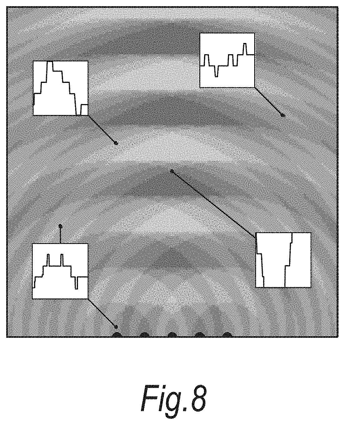
[0032] FIG. 8 shows an acoustic field generated at a focal point by a square wave modulation.
DETAILED DESCRIPTION
[0033] In an example embodiment of the method, firstly the 3D position of a focal point is decided. A phased array is arranged to create an acoustic field, with the phases and amplitudes of each transducer calculated to achieve a high pressure at the focal point and a low pressure in surrounding areas. Two states then exist, firstly the focal point state, with the computed phases and amplitudes, and secondly the off state, with all of the transducers of a phased array set at zero amplitude. A frequency at which to modulate the feedback is then chosen in dependence on the desired feel of the feedback. Then a modulation waveform is chosen at the desired frequency, the modulation frequency chosen to minimise or reduce the audible sound produced at the focal point. An example modulation waveform is a cosine waveform. The modulation waveform is then applied to the operation of the transducers to interpolate between the two states identified above.
[0034] A more specific example, as applied to a particular haptic feedback system, is now described with reference to FIG. 1.
[0035] FIG. 1 shows an example haptic feedback system 10 comprising a transducer array 12, a screen 14, a projector 16, a hand tracker 20, a PC 22, a driving unit 24, and a user's hand 26. The system 10 is shown to illustrate the invention, which is in no way limited to a particular system for producing haptic feedback using ultrasound. The transducer array 12 is located underneath the screen 14 and arranged such that pressure patterns may be transmitted through the screen 14 to a region above the screen 14. In this particular embodiment, the transducer array comprises 320 muRata MA40S4S transducers arranged in a 16.times.20 grid formation. Each transducer unit is 10 mm in diameter and the transducers are positioned with no gap between them in order to minimise the transducer array 12 footprint. The transducers produce a large amount of sound pressure (20 Pascals of pressure at a distance of 30 cm) and have a wide angle of directivity (60 degrees). The transducers are arranged to transmit ultrasound waves at a frequency of 40 kHz. The projector 16 is arranged to project visual information onto the screen 14 from above the screen 14 as shown. In an alternative embodiment, the projector may be placed between the transducer array and the screen, with the projection coming from below the screen.
[0036] A user interacts with this visual information and the movement and position of the user's hand 26 is tracked by the hand tracker 20. In this particular embodiment, the hand tracker 20 is a Leap Motion controller arranged to provide the 3D coordinates of the user's fingertips and palm at up to 200 frames per second. The system 10 is controlled by a PC 22, which sends control data to the projector 16, receives user data from the hand tracker 20, and controls the drive unit 24 for driving the transducer array 12. The PC 22 controls the driving unit 24 such that a pressure pattern is created in the region above the transducer array 12. In response to the hand movements of a user, the PC 22 may drive the driving unit 24 to cause the transducer array 12 to change the pressure pattern forms d above the transducer array 12.
[0037] In order to compute the amplitude and phase of the acoustic wave each acoustic transducer must transmit for the desired pressure pattern to be created, an algorithm adapted from that proposed by Gavrilov ("The possibility of generating focal regions of complex configurations in application to the problems of stimulation of human receptor structures by focused ultrasound", L. R. Gavrilov, 2008, Acoustical Physics Volume. 54, Issue 2, pp 269-273, Print ISSN 1063-7710) may be used. A volumetric box is defined above the transducer array 12. Within the box, a plurality of control points are defined. The control points may represent points where a maximum pressure value is desired, or points where minimum pressure values are desired. The pressure values are maximised or minimised by maximising or minimising the intensity of the ultrasound emitted by the transducer array 12 which is incident at the control points.
[0038] An algorithm is used to model the outputs of each of the transducers in the transducer array 12 required to obtain each of the desired pressure patterns which may be created within the volume defined above the transducer array 12. The algorithm may be split into three steps.
[0039] Firstly, the acoustic field generated by a single transducer is calculated to create a large modelled volume. Thereby, the phase and amplitude at any point within the modelled volume may be determined by offsetting the sample transducer for the position, phase, and amplitude, of each of the transducers in the real transducer array, and combining these values.
[0040] Secondly, the control points are defined in the 3D volume above the transducer array such that the control points take on the required distribution. The control points may be points of maximum intensity or minimum intensity (also known as null points). In addition to a 3D location, the desired modulation frequency of the maximum control points may be specified. Thirdly, the optimal phases are calculated using a minimum norm solver so that the resulting acoustic field is as close as possible to that specified by the control points. There may be more than one solution that will create an optimal focussing to the control points, but some solutions create a higher intensity than others. Solutions are therefore iteratively generated to find the one that creates the highest intensity.
[0041] The method according to an aspect of the invention comprises obtaining a modulation frequency that produces the required tactile sensation. For example, a relatively slow modulation frequency of 16 Hz would provide a slow, pulsing, sensation. A higher modulation frequency of 200 Hz would produce a near-continuous feeling. A modulation waveform is then selected at that frequency, which produces little or no audible sound at the feedback point. The modulation waveform may comprise an interpolation based on the required phase and amplitude of the waveform calculated as described above.
[0042] FIGS. 2 to 6 show a graph on the left hand side which represents the modulation waveform applied to the ultrasound emitted by an ultrasound transducer. The graph on the right hand side of the figures represents the audible waveform created at the focal point of the ultrasound transducer. Generally, the greater the amplitude and the more jagged the feedback waves created at the focal point, the louder the sound being produced will be.
[0043] In prior art systems, the modulation of the ultrasound corresponds to a simple square wave pattern, as shown in the graph on the left hand side of FIG. 2, where the array of transducers is simply turned on and off at the modulation frequency. The graph on the right hand side of FIG. 2 shows the waveform produced at the focal point of the ultrasound transducer when using a square wave modulation pattern. As is clear, the waveform is far from smooth and also the amplitude of the waveform is relatively high. This will result in a potentially loud and irritating sound being produced a the focal point of the haptic feedback system.
[0044] FIG. 3 shows an alternative modulation waveform, where the ultrasound is varied according to a linear interpolation. As can be seen in the graph on the right hand side of FIG. 3, the waveform produced at the focal point is smoother than that shown in FIG. 2, with an amplitude which is significantly smaller. Therefore, the sound produced at the focal point will be reduced compared to a square wave modulation.
[0045] FIG. 4 shows an alternative modulation waveform, where the ultrasound is varied according to a cosine interpolation. As can be seen in the graph on the right hand side of FIG. 4, the waveform produced at the focal point is smoother than that shown in FIG. 2, with an amplitude which is significantly smaller. Therefore, the sound produced at the focal point will be reduced compared to a square wave modulation.
[0046] FIG. 5 shows an alternative modulation waveform, where the ultrasound is varied according to a parametric speaker interpolation. As can be seen in the graph on the right hand side of FIG. 5, the waveform produced at the focal point is smoother than that shown in FIG. 2, with an amplitude which is significantly smaller. Therefore, the sound produced at the focal point will be reduced compared to the square wave modulation.
[0047] FIGS. 6, 7, and 8, show the acoustic field of audible waveforms that is produced from different modulation waveforms when a focal point is created from five point sources. The waveform at various points throughout the field are highlighted for comparison. FIG. 6 represents a cosine interpolation, FIG. 7 represents a parametric speaker interpolation, and FIG. 8 represents a square wave modulation method. As can be seen, FIG. 6 shows the smoothest, most uniform field. FIG. 7 shows a field which is not as smooth and uniform as FIG. 6, though still considerably smoother and more uniform than that shown in FIG. 8. Therefore it is evident that the cosine interpolation provides the optimum modulation compared to the others discussed. On investigation, the skilled person may discover alternative modulation waveforms which perform as well as or better than a cosine interpolation, whilst still falling within the scope of the present invention.
[0048] Whilst the present invention has been described and illustrated with reference to particular embodiments, it will be appreciated by those of ordinary skill in the art that the invention lends itself to many different variations not specifically illustrated herein.
[0049] Where in the foregoing description, integers or elements are mentioned which have known, obvious or foreseeable equivalents, then such equivalents are herein incorporated as if individually set forth. Reference should be made to the claims for determining the true scope of the present invention, which should be construed so as to encompass any such equivalents. It will also be appreciated by the reader that integers or features of the invention that are described as preferable, advantageous, convenient or the like are optional and do not limit the scope of the independent claims. Moreover, it is to be understood that such optional integers or features, whilst of possible benefit in some embodiments of the invention, may not be desirable, and may therefore be absent, in other embodiments.
* * * * *
D00000
D00001
D00002
D00003
D00004
D00005
D00006
D00007
XML
uspto.report is an independent third-party trademark research tool that is not affiliated, endorsed, or sponsored by the United States Patent and Trademark Office (USPTO) or any other governmental organization. The information provided by uspto.report is based on publicly available data at the time of writing and is intended for informational purposes only.
While we strive to provide accurate and up-to-date information, we do not guarantee the accuracy, completeness, reliability, or suitability of the information displayed on this site. The use of this site is at your own risk. Any reliance you place on such information is therefore strictly at your own risk.
All official trademark data, including owner information, should be verified by visiting the official USPTO website at www.uspto.gov. This site is not intended to replace professional legal advice and should not be used as a substitute for consulting with a legal professional who is knowledgeable about trademark law.