Winding Device For Automatic Watch
WILLEMIN; Michel ; et al.
U.S. patent application number 17/246891 was filed with the patent office on 2022-04-14 for winding device for automatic watch. This patent application is currently assigned to The Swatch Group Research and Development Ltd. The applicant listed for this patent is The Swatch Group Research and Development Ltd. Invention is credited to Jerome FAVRE, Nicolas LIVAT, Michel WILLEMIN.
| Application Number | 20220113682 17/246891 |
| Document ID | / |
| Family ID | |
| Filed Date | 2022-04-14 |


| United States Patent Application | 20220113682 |
| Kind Code | A1 |
| WILLEMIN; Michel ; et al. | April 14, 2022 |
WINDING DEVICE FOR AUTOMATIC WATCH
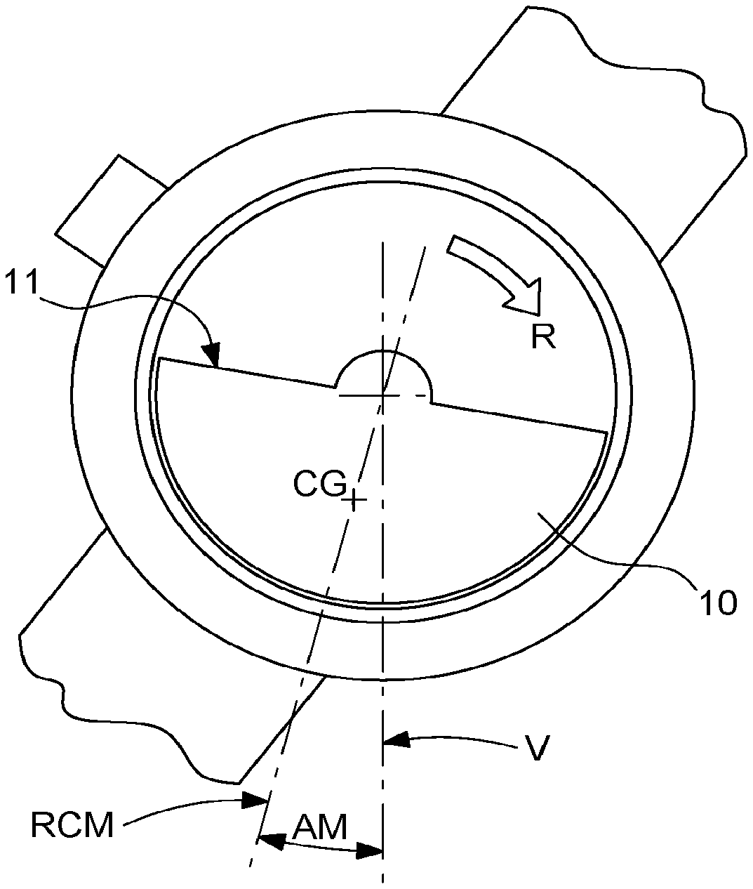
Abstract
The winding device includes a motorization device for driving a watch holder carrying at least one automatic watch with a mobile oscillating mass, and a measuring device for measuring the variation in the resistive torque opposed to the motorization device by the watch holder equipped with watches, depending on the degree of winding of the watches. The measuring device includes a speed measuring device to determine the speed and/or the variation in the speed of the motorization device, and/or include a torque measuring device to determine the value of the torque and/or the variation in the torque at the watch holder, and/or include a current measuring device to determine the value of the current and/or the variation in the current of an electric motor of the motorization device.
| Inventors: | WILLEMIN; Michel; (Preles, CH) ; FAVRE; Jerome; (Neuchatel, CH) ; LIVAT; Nicolas; (Cressier, CH) | ||||||||||
| Applicant: |
|
||||||||||
|---|---|---|---|---|---|---|---|---|---|---|---|
| Assignee: | The Swatch Group Research and
Development Ltd Marin CH |
||||||||||
| Appl. No.: | 17/246891 | ||||||||||
| Filed: | May 3, 2021 |
| International Class: | G04C 1/06 20060101 G04C001/06; G04C 1/12 20060101 G04C001/12 |
Foreign Application Data
| Date | Code | Application Number |
|---|---|---|
| Oct 14, 2020 | EP | 20201698.6 |
Claims
1. A winding device for an automatic watch with a mobile oscillating mass, including at least one watch holder arranged to carry at least one automatic watch, and including motorisation means for driving said at least one watch holder, wherein said device includes measuring means which are arranged to measure the variation in the resistive torque which is opposed to said motorisation means by a mobile equipment consisting of, on the one hand, all said watch holders driven by said motorisation means, and on the other hand all the watches that all said watch holders driven by said motorisation means carry, depending on the degree of winding of said watches, and wherein said measuring means include speed measuring means to determine the speed and/or the variation in the speed of said motorisation means, and/or include torque measuring means to determine the value of the torque and/or the variation in the torque at least at one said watch holder, and/or include current measuring means to determine the value of the current and/or the variation in the current at least at one electric motor that said motorisation means include.
2. The winding device according to claim 1, wherein said measuring means include said speed measuring means which include fixed optical means arranged to follow a mobile locator that a said watch holder includes, and coupled with a time base that said winding device includes or with which said winding device is interfaced, or to follow an oscillating mass of a said watch including a transparent back allowing the observation of said oscillating mass.
3. The winding device according to claim 2, wherein at least one said watch holder is arranged to make visible the oscillating mass of each watch carrying a transparent back that it carries, and wherein viewing means are arranged to follow and/or determine the angular position of an oscillating mass of a given watch between a dead angle corresponding to the unwound state of said watch and a limit winding angle corresponding to the fully wound state of said watch, and wherein said measuring means are arranged to send a stop signal to said motorisation means when said limit winding angle is reached.
4. The winding device according to claim 1, wherein said motorisation means include a direct current electric motor which is not speed-controlled.
5. The winding device according to claim 4, wherein said measuring means include said speed measuring means which are arranged to send a stop signal to said motorisation means when said speed of said motorisation means is less, by a predetermined value, than the speed of said motorisation means at the start of the cycle when at least one watch carried by at least one said holder watch is in an unwound state.
6. The winding device according to claim 5, wherein said predetermined value is comprised between 0.2% and 1.4%.
7. The winding device according to claim 6, wherein said predetermined value is comprised between 0.6% and 1.0%.
8. The winding device according to claim 1, wherein said measuring means include said torque measuring means, which are arranged to send a stop signal to said motorisation means when the value of the measured torque is stabilised with a variation less than 1.0%.
9. The winding device according to claim 1, wherein said measuring means include said torque measuring means, which are arranged to determine the real angular position of the centre of mass of said mobile equipment, to compare it with a theoretical angular position corresponding to the fully wound state of each said watch, and are arranged to send a stop signal to said motorisation means when said real and theoretical positions are equal.
10. The winding device according to claim 8, wherein said measuring means include said current measuring means to determine the value of the current and/or the variation in the current at said electric motor, and which constitute said torque measuring means.
11. The winding device according to claim 1, wherein said measuring means include said current measuring means to determine the value of the current and/or the variation in the current at said electric motor, and arranged to send a stop signal to said motorisation means when the current consumption is, for a duration greater than 80 seconds, more than 4.0% higher than the consumption at the start of the cycle when at least one watch carried by at least one said watch holder is in an unwound state.
12. The winding device according to claim 11, wherein said measuring means are arranged to send a said stop signal to said motorisation means when the current consumption is, for a duration greater than 40 seconds, more than 2.0% higher than the consumption at the start of the cycle when at least one watch carried by at least one said watch holder is in an unwound state.
13. The winding device according to claim 1, wherein measuring means are arranged to determine a difference in resistance according to the direction of rotation of said watch holder, and to impose a rotation of said watch holder in the direction wherein it has the greatest resistance.
14. The winding device according to claim 1, wherein at least one said watch holder carries a single watch.
15. The winding device according to claim 14, wherein each said watch holder carries a single watch.
16. The winding device according to claim 1, wherein said winding device includes a single said watch holder.
Description
FIELD OF THE INVENTION
[0001] The invention relates to an automatic device for winding automatic watches.
[0002] The invention also relates to a universal device for winding and time setting a watch, including such an automatic device for winding watches.
[0003] The invention relates to the field of smart devices, such as smart winders, for maintaining watches in immediate serviceability, displaying the correct time, and with sufficient power reserve to be worn for a few hours, while avoiding premature wear of the watch by incessant and unnecessary windings.
BACKGROUND OF THE INVENTION
[0004] Document EP3339984 in the name of The Swatch Group Research and Development Ltd describes a smart device for winding watches. This device is subject to constant improvements.
[0005] In particular, one of the developments relates to a smart winder, based on limiting the unnecessary winding of automatic watches, and whose main purpose is to limit the recharging of the automatic barrel of the watch to what is strictly necessary, to avoid any premature wear of the watch, caused by excessive windings.
[0006] To identify whether a watch is fully charged, the amplitude of the balance-spring is measured by an acoustic method. However, it remains difficult to perform an accurate and reliable measurement of the amplitude, due to the background noise, at a reasonable cost, and with low power consumption. In addition, for optimal precision, this method requires contact with the measured watch, or at least the installation of an air microphone very close to the resonator of the watch, in a low-noise environment.
SUMMARY OF THE INVENTION
[0007] The invention proposes to measure the winding or coiling rate of a mechanical watch with automatic winding, by measuring the influence that the winding mechanism has on the automatic winding device of automatic watches, hereinafter referred to as winder.
[0008] An advantageous application relates to the production of a smart winder with torque measurement.
[0009] To this end, the invention relates to a winding device for an automatic watch with a mobile oscillating mass, according to claim 1.
BRIEF DESCRIPTION OF THE DRAWINGS
[0010] Other features and advantages of the invention will become apparent upon reading the detailed description which follows, with reference to the appended drawings, where:
[0011] FIG. 1 shows, schematically and in front view, the back of an automatic watch, positioned with the plane of its oscillating mass parallel to the field of gravity, in an unwound state of the watch, wherein the dead angle is almost zero;
[0012] FIG. 2 shows, similarly to FIG. 1, the same watch in a fully wound state, where the blind angle is maximum;
[0013] FIG. 3 is a curve which represents, on the y-axis, the winder speed, which is variable as a function of the number of winding revolutions on the x-axis;
[0014] FIG. 4 is a block diagram which includes the various measuring means that can be used to measure the variation in the resistive torque which is opposed to the motorisation means, and therefore the degree of winding of the watch;
[0015] FIG. 5 is a sectional view of a watch holder adapted for an automatic watch including a transparent background, under which a camera tracks the value of the blind angle;
[0016] FIG. 6 shows, schematically, in exploded perspective, a winding device according to the invention, in a variant with optical measurement.
DETAILED DESCRIPTION OF THE PREFERRED EMBODIMENTS
[0017] The invention proposes to supplement the acoustic measurement of the amplitude with a measurement of the influence that the winding state of the watch has on the winder. This is because the winding angle of the oscillating mass (also called the dead angle) increases with the winding rate, since the barrel spring opposes the torque of the mass.
[0018] The centre of gravity CG of the oscillating mass 10 is eccentric, and is located, relative to its axis of rotation, on a radial which is called here radial of the centre of mass RCM. If, in a simplified approach, the friction is neglected, the system of forces applied to the oscillating mass 10 boils down to the opposition between the return torque exerted by the barrel geartrain on the one hand, and the torque exerted by gravitation on the oscillating mass 10. When an automatic watch is disposed with the plane of the oscillating mass parallel to the field of gravity, the angle AM that this radial of the centre of mass RCM makes with the vertical V of the place is called "dead angle".
[0019] When the watch is unwound, and an hour torque R is applied thereto in this same plane to recharge it, this dead angle AM is very small: the right edge 11 that an oscillating mass 10 generally includes remains almost horizontal, as shown in FIG. 1.
[0020] On the other hand, when the watch is fully wound, and under the same conditions, and as visible in FIG. 2, the dead angle AM is considerably higher (for example 24.degree. more for a standard movement ETA 2824, well known to the person skilled in the art and very widespread), since the torque of the barrel spring is maximum and opposes the torque of the oscillating mass 10: the balance is only possible at a large angle so that the gravity torque balances that coming from the barrel.
[0021] In short, this change of angle has the effect of shifting the centre of mass of the entire watch, which has a measurable unbalance effect on the winder 100 on which the watch is placed, through a watch holder 1.
[0022] Three non-limiting methods, and which can be combined, are proposed for measuring this effect.
[0023] Speed measurement is advantageous because it is an efficient and inexpensive method. The winder 100 is equipped with a direct current motor 21 which is not speed-controlled, only the supply voltage is constant (imposed by the algorithm). When the watch is discharged, the torque opposed by the watch is at the minimum, and the winder speed is at the maximum. When the watch is fully wound, the torque opposed by the watch is at the maximum, and the winder speed is at the minimum. FIG. 3 shows the evolution of the winder speed (in revolutions per second) as a function of the number of winding revolutions 100, during the complete winding of a watch. It can be seen that this speed of rotation decreases by approximately 0.8% when the watch is fully charged (after approximately 2000 winding revolutions). In this embodiment, the winder 100 speed is simply carried out using a fixed optical sensor 31 and a mobile locator 32 integral with the rotating watch holder 1.
[0024] Torque measurement is an efficient method but more expensive than the previous one. The torque opposing the oscillating mass 10 increases as the winding increases, until reaching a plateau when the watch is fully wound. The torque can be measured with a torque tester or torquemeter mounted on the watch holder. The advantage of a torquemeter is its high sensitivity.
[0025] The measurement of the current injected into the motor of the winder is a cheap, but delicate method, unless averaging is carried out long enough. The current of a direct current motor as used in the winder is proportional to its charge, and therefore to the torque opposed by the rotor made of the watch holder and the watch with its oscillating mass 10. Measurements show that a winder equipped with a discharged watch consumes around 2 mA (at 1V), with periodic variations that can reach +/-0.5 mA (or +/-25%) during one revolution of the watch holder. It can be shown that the average current should theoretically increase by only 40 .mu.A when the watch is fully charged, that is to say an average increase of only 2% compared to the reference 2 mA. If the current measurement is averaged long enough (typically several revolutions, that is to say a few tens of seconds, which corresponds to a low-pass filter, which cancels the periodic variations), this 2% increase in the average current becomes possible to detect compared to noise.
[0026] Thus, more particularly, the invention relates to a winding device 100 for an automatic watch with a mobile oscillating mass.
[0027] This device 100 includes at least one watch holder 1, which is arranged to carry at least one automatic watch. The device 100 includes motorisation means 2 for driving, in particular at least in rotation, the at least one watch holder 1, and more particularly each watch holder 1 that it includes.
[0028] According to the invention, the device 100 includes measuring means 3, which are arranged to measure the variation in the resistive torque which is opposed to the motorisation means 2 by a mobile equipment consisting of, on the one hand, all the watch holders 1 driven by the motorisation means 2, and on the other hand all the watches that all these same watch holders 1 carry, depending on the degree of winding of the watches. And these measuring means 3 include speed measuring means 4 to determine the speed and/or the variation in the speed of the motorisation means 2, and/or include torque measuring means 5 to determine the value of the torque and/or the variation in the torque at least at one watch holder 1, and/or include current measuring means 6 to determine the value of the current and/or the variation in the current at least at one electric motor 21 that the motorisation means 2 include.
[0029] More particularly, the measuring means 3 include such speed measuring means 4, which include fixed optical means 31 arranged to follow a mobile locator 32 that a watch holder 1 includes, and which are coupled with a time base 9, that the winding device 100 includes or with which the winding device 100 is interfaced. In an alternative, these optical means 31 are arranged to follow an oscillating mass 10 of at least one watch including a transparent back allowing the observation of the oscillating mass 10, or, more particularly, of each watch equipped with such a transparent back.
[0030] Thus, more particularly, at least one watch holder 1 is arranged to make visible the oscillating mass 10 of each watch carrying a transparent back that it carries, and viewing means 33 are arranged to follow and/or determine the angular position of an oscillating mass 10 of a given watch between a dead angle corresponding to the unwound state of the watch and a limit winding angle corresponding to the fully wound state of the watch. And the measuring means 3 are then advantageously arranged to send a stop signal to the motor means 2 when the limit winding angle is reached, to avoid any unnecessary winding, and therefore any wear of the watch.
[0031] More particularly, the motorisation means 2 include a direct current electric motor 21, which is not speed-controlled.
[0032] More particularly, the measuring means 3 then include speed measuring means 4, which are arranged to send a stop signal to the motorisation means 2 when the speed of the motorisation means 2 is less, by a predetermined value, than the speed of the motorisation means 2 at the start of the cycle when at least one watch carried by at least one watch holder 1 is in an unwound state. More particularly, this predetermined value is comprised between 0.2% and 1.4%. Still more particularly, the predetermined value is comprised between 0.6% and 1.0%.
[0033] More particularly, the measuring means 3 include torque measuring means 5, which are arranged to send a stop signal to the motorisation means 2 when the value of the measured torque is stabilised with a variation less than a predetermined threshold, such as 1.0% in a particular non-limiting variant.
[0034] More particularly, the measuring means 3 include torque measuring means 5, which are arranged to determine the real angular position of the centre of mass of the mobile equipment mentioned above, to compare it with a theoretical angular position corresponding to the fully wound state of each watch, and are arranged to send a stop signal to the motorisation means 2 when these real and theoretical positions are equal.
[0035] More particularly, the measuring means 3 include current measuring means 6 to determine the value of the current and/or the variation in the current at the motor that the motorisation means 2 include, in particular an electric motor 21, and which constitute torque measuring means 5.
[0036] More particularly, the measuring means 3 include such current measuring means 6 to determine the value of the current and/or the variation in the current at the electric motor 21, and which are arranged to send a stop signal to the motorisation means 2 when the current consumption is, for a duration greater than 80 seconds, more than 4.0% higher than the consumption at the start of the cycle when at least one watch carried by at least one watch holder 1 is in an unwound state. More particularly, these measuring means 3 are arranged to send this signal when the current consumption is, for a duration greater than 40 seconds, more than 2.0% higher than the consumption at the start of the cycle when at least one watch carried by at least one watch holder 1 is in an unwound state.
[0037] More particularly, the measuring means 3 are arranged to determine a difference in resistance according to the direction of rotation of a watch holder 1, and to impose a rotation of the watch holder 1 in the direction wherein it has the greatest resistance. This allows to determine the presence of automatic watches which are designed for winding in one direction only, and for freewheeling movement in the other direction; thus each movement imparted to the watch holder 1 is effective since it is used for rewinding.
[0038] More particularly, at least one watch holder 1 carries a single watch. Still more particularly, each watch holder 1 carries a single watch.
[0039] More particularly, the winding device 100 includes a single watch holder 1.
[0040] The invention has several major advantages, regardless of its embodiment:
[0041] no need to install an air or contact microphone;
[0042] independence from ambient noise, which generally constitutes a major obstacle to precise and reliable measurements;
[0043] no need to install a second wireless-powered on-board electronic circuit at the watch holder;
[0044] ease of speed measurement, with a very simple algorithm compared to that required for acoustic amplitude measurement;
[0045] high resolution of speed or torque measurements, however with a potentially high noise;
[0046] a relative measurement of the effect on the winder works with any automatic watch;
[0047] these measurements allow to quickly determine the correct rewinding direction.
* * * * *
D00000
D00001
D00002
D00003
XML
uspto.report is an independent third-party trademark research tool that is not affiliated, endorsed, or sponsored by the United States Patent and Trademark Office (USPTO) or any other governmental organization. The information provided by uspto.report is based on publicly available data at the time of writing and is intended for informational purposes only.
While we strive to provide accurate and up-to-date information, we do not guarantee the accuracy, completeness, reliability, or suitability of the information displayed on this site. The use of this site is at your own risk. Any reliance you place on such information is therefore strictly at your own risk.
All official trademark data, including owner information, should be verified by visiting the official USPTO website at www.uspto.gov. This site is not intended to replace professional legal advice and should not be used as a substitute for consulting with a legal professional who is knowledgeable about trademark law.