Camera Optical Lens
Li; Wanxia
U.S. patent application number 17/138780 was filed with the patent office on 2022-04-14 for camera optical lens. The applicant listed for this patent is Raytech Optical (Changzhou) Co., Ltd. Invention is credited to Wanxia Li.
| Application Number | 20220113512 17/138780 |
| Document ID | / |
| Family ID | 1000005331384 |
| Filed Date | 2022-04-14 |


| United States Patent Application | 20220113512 |
| Kind Code | A1 |
| Li; Wanxia | April 14, 2022 |
CAMERA OPTICAL LENS
Abstract
Disclosed is a camera optical lens, including nine lenses, and the nine lenses from an object side to an image side are: a first lens with a negative refractive power, a second lens with a positive refractive power, a third lens with a negative refractive power, a fourth lens with a positive refractive power, a fifth lens with a positive refractive power, a sixth lens with a positive refractive power, a seventh lens with a negative refractive power, an eighth lens with a positive refractive power and an ninth lens with a negative refractive power. The camera optical lens satisfies: -5.00.ltoreq.f1/f.ltoreq.-2.00; 2.50.ltoreq.d13/d14.ltoreq.10.00. The camera optical lens has good optical performance, and meets the design requirements of a large aperture, wide-angle and ultra-thin.
| Inventors: | Li; Wanxia; (Shenzhen, CN) | ||||||||||
| Applicant: |
|
||||||||||
|---|---|---|---|---|---|---|---|---|---|---|---|
| Family ID: | 1000005331384 | ||||||||||
| Appl. No.: | 17/138780 | ||||||||||
| Filed: | December 30, 2020 |
| Current U.S. Class: | 1/1 |
| Current CPC Class: | G02B 9/64 20130101; G02B 13/0045 20130101 |
| International Class: | G02B 13/00 20060101 G02B013/00; G02B 9/64 20060101 G02B009/64 |
Foreign Application Data
| Date | Code | Application Number |
|---|---|---|
| Oct 14, 2020 | CN | 202011097549.9 |
Claims
1. A camera optical lens, comprising nine lenses, the nine lenses from an object side to an image side being: a first lens with a negative refractive power; a second lens with a positive refractive power; a third lens with a negative refractive power; a fourth lens with a positive refractive power; a fifth lens; a sixth lens with a positive refractive power; a seventh lens with a negative refractive power; an eighth lens with a positive refractive power; and an ninth lens with a negative refractive power; wherein the camera optical lens satisfies following conditions: -5.00.ltoreq.f1/f.ltoreq.-2.00;2.50.ltoreq.d13/d14.ltoreq.10.00; where f denotes a focal length of the camera optical lens; f1 denotes a focal length of the first lens; d13 denotes an on-axis thickness of the seventh lens; d14 denotes an on-axis distance from an image-side surface of the seventh lens to an object-side surface of the eighth lens.
2. The camera optical lens according to claim 1, further satisfying following conditions: 2.50.ltoreq.R11/R12.ltoreq.6.50; where R11 denotes a central curvature radius of an object-side surface of the sixth lens; R12 denotes a central curvature radius of an image-side surface of the sixth lens.
3. The camera optical lens according to claim 1, further satisfying following conditions: 2.49.ltoreq.(R1+R2)/(R1-R2).ltoreq.15.47;0.02.ltoreq.d1/TTL.ltoreq.0.06; where R1 denotes a central curvature radius of an object-side surface of the first lens; R2 denotes a central curvature radius of an image-side surface of the first lens; d1 denotes an on-axis thickness of the first lens; TTL denotes a total track length of the camera optical lens.
4. The camera optical lens according to claim 1, further satisfying following conditions: 0.35.ltoreq.f2/f.ltoreq.1.13;-2.32.ltoreq.(R3+R4)/(R3-R4).ltoreq.-0.76;0.- 05.ltoreq.d3/TTL.ltoreq.0.16; where f2 denotes a focal length of the second lens; R3 denotes a central curvature radius of an object-side surface of the second lens; R4 denotes a central curvature radius of an image-side surface of the second lens; d3 denotes an on-axis thickness of the second lens; TTL denotes a total track length of the camera optical lens.
5. The camera optical lens according to claim 1, further satisfying following conditions: -3.29.ltoreq.f3/f.ltoreq.-1.04;1.57.ltoreq.(R5+R6)/(R5-R6).ltoreq.5.06;0.- 02.ltoreq.d5/TTL.ltoreq.0.09; where f3 denotes a focal length of the third lens; R5 denotes a central curvature radius of an object-side surface of the third lens; R6 denotes a central curvature radius of an image-side surface of the third lens; d5 denotes an on-axis thickness of the third lens; TTL denotes a total track length of the camera optical lens.
6. The camera optical lens according to claim 1, further satisfying following conditions: 0.88.ltoreq.f4/f.ltoreq.2.87;-1.49.ltoreq.(R7+R8)/(R7-R8).ltoreq.-0.45;0.- 04.ltoreq.d7/TTL.ltoreq.0.14; where f4 denotes a focal length of the fourth lens; R7 denotes a central curvature radius of an object-side surface of the fourth lens; R8 denotes a central curvature radius of an image-side surface of the fourth lens; d7 denotes an on-axis thickness of the fourth lens; TTL denotes a total track length of the camera optical lens.
7. The camera optical lens according to claim 1, further satisfying following conditions: -163.02.ltoreq.f5/f.ltoreq.664.49;-54.65.ltoreq.(R9+R10)/(R9-R10).ltoreq.- 622.16;0.02.ltoreq.d9/TTL.ltoreq.0.08; where f5 denotes a focal length of the fifth lens; R9 denotes a central curvature radius of an object-side surface of the fifth lens; R10 denotes a central curvature radius of an image-side surface of the fifth lens; d9 denotes an on-axis thickness of the fifth lens; TTL denotes a total track length of the camera optical lens.
8. The camera optical lens according to claim 1, further satisfying following conditions: 3.18.ltoreq.f6/f.ltoreq.11.86;0.69.ltoreq.(R11+R12)/(R11-R12).ltoreq.3.03- ;0.03.ltoreq.d11/TTL.ltoreq.0.10; where f6 denotes a focal length of the sixth lens; R11 denotes a central curvature radius of an object-side surface of the sixth lens; R12 denotes a central curvature radius of an image-side surface of the sixth lens; d11 denotes an on-axis thickness of the sixth lens; TTL denotes a total track length of the camera optical lens.
9. The camera optical lens according to claim 1, further satisfying following conditions: -10.88.ltoreq.f7/f.ltoreq.-3.51;-15.70.ltoreq.(R13+R14)/(R13-R14).ltoreq.- -4.97;0.02.ltoreq.d13/TTL.ltoreq.0.10; where f7 denotes a focal length of the seventh lens; R13 denotes a central curvature radius of an object-side surface of the seventh lens; R14 denotes a central curvature radius of the image-side surface of the seventh lens; TTL denotes a total track length of the camera optical lens.
10. The camera optical lens according to claim 1, further satisfying following conditions: 1.05.ltoreq.f8/f.ltoreq.3.63;-7.36.ltoreq.(R15+R16)/(R15-R16).ltoreq.-2.3- 6;0.06.ltoreq.d15/TTL.ltoreq.0.19; where f8 denotes a focal length of the eighth lens; R15 denotes a central curvature radius of the object-side surface of the eighth lens; R16 denotes a central curvature radius of an image-side surface of the eighth lens; d15 denotes an on-axis thickness of the eighth lens; TTL denotes a total track length of the camera optical lens.
11. The camera optical lens according to claim 1, further satisfying following conditions: -2.28.ltoreq.f9/f.ltoreq.-0.70;0.77.ltoreq.(R17+R18)/(R17-R18).ltoreq.2.9- 0;0.04.ltoreq.d17/TTL.ltoreq.0.13; where f9 denotes a focal length of the ninth lens; R17 denotes a central curvature radius of an object-side surface of the ninth lens; R18 denotes a central curvature radius of an image-side surface of the ninth lens; d17 denotes an on-axis thickness of the ninth lens; TTL denotes a total track length of the camera optical lens.
Description
TECHNICAL FIELD
[0001] The present disclosure relates to the field of optical lens, particular, to a camera optical lens suitable for handheld devices, such as smart phones and digital cameras, and imaging devices, such as monitors or PC lenses.
BACKGROUND
[0002] With the emergence of smart phones in recent years, the demand for miniature camera lens is increasing day by day, but in general the photosensitive devices of camera lens are nothing more than a charge coupled device (CCD) or a complementary metal-oxide semiconductor sensor (CMOS sensor), and as the progress of the semiconductor manufacturing technology makes the pixel size of the photosensitive devices become smaller, plus the current development trend of electronic products towards better functions and thinner and smaller dimensions, miniature camera lens with good imaging quality therefore have become a mainstream in the market.
[0003] In order to obtain better imaging quality, the lens that is traditionally equipped in mobile phone cameras adopts a structure of a three-piece, four-piece, or even five-piece, or six-piece lens. Also, with the development of technology and the increase of the diverse demands of users, and as the pixel area of photosensitive devices is becoming smaller and smaller and the requirement of the system on the imaging quality is improving constantly, a nine-piece lens structure gradually appears in lens designs. The present nine-piece lens structure generally has good optical performance, however an optical focal length, lens spacing, a lens shape thereof are still arranged unreasonably, so that the nine-piece lens cannot meet a design requirements of a large aperture, ultra-thin and wide-angle in the case when the lens structure remains good optical characteristics.
SUMMARY
[0004] Some embodiments of this disclosure provide a camera optical lens, comprising nine lenses, the nine lenses from an object side to an image side being: a first lens with a negative refractive power; a second lens with a positive refractive power; a third lens with a negative refractive power; a fourth lens with a positive refractive power; a fifth lens; a sixth lens with a positive refractive power; a seventh lens with a negative refractive power; an eighth lens with a positive refractive power; and an ninth lens with a negative refractive power; wherein the camera optical lens satisfies following conditions: -5.00.ltoreq.f1/f.ltoreq.-2.00; 2.50.ltoreq.d13/d14.ltoreq.10.00; where, f denotes a focal length of the camera optical lens; f1 denotes a focal length of the first lens; d13 denotes an on-axis thickness of the seventh lens; and d14 denotes an on-axis distance from an image-side surface of the seventh lens to an object-side surface of the eighth lens.
[0005] As an improvement, the camera optical lens further satisfies following conditions: 2.50.ltoreq.R11/R12.ltoreq.6.50; where R11 denotes a central curvature radius of an object-side surface of the sixth lens; R12 denotes a central curvature radius of an image-side surface of the sixth lens.
[0006] As an improvement, the camera optical lens further satisfies following conditions: 2.49.ltoreq.(R1+R2)/(R1-R2).ltoreq.15.47; 0.02.ltoreq.d1/TTL.ltoreq.0.06; where, R1 denotes a central curvature radius of an object-side surface of the first lens; R2 denotes a central curvature radius of an image-side surface of the first lens; d1 denotes an on-axis thickness of the first lens; TTL denotes a total track length of the camera optical lens.
[0007] As an improvement, the camera optical lens further satisfies following conditions: 0.35.ltoreq.f2/f.ltoreq.1.13; -2.32.ltoreq.(R3+R4)/(R3-R4).ltoreq.-0.76; 0.05.ltoreq.d3/TTL.ltoreq.0.16; where f2 denotes a focal length of the second lens; R3 denotes a central curvature radius of an object-side surface of the second lens; R4 denotes a central curvature radius of an image-side surface of the second lens; d3 denotes an on-axis thickness of the second lens; TTL denotes a total track length of the camera optical lens.
[0008] As an improvement, the camera optical lens further satisfies following conditions: -3.29.ltoreq.f3/f.ltoreq.-1.04; 1.57.ltoreq.(R5+R6)/(R5-R6).ltoreq.5.06; 0.02.ltoreq.d5/TTL.ltoreq.0.09; where f3 denotes a focal length of the third lens; R5 denotes a central curvature radius of an object-side surface of the third lens; R6 denotes a central curvature radius of an image-side surface of the third lens; d5 denotes an on-axis thickness of the third lens; TTL denotes a total track length of the camera optical lens.
[0009] As an improvement, the camera optical lens further satisfies following conditions: 0.88.ltoreq.f4/f.ltoreq.2.87; -1.49.ltoreq.(R7+R8)/(R7-R8).ltoreq.-0.45; 0.04.ltoreq.d7/TTL.ltoreq.0.14; where f4 denotes a focal length of the fourth lens; R7 denotes a central curvature radius of an object-side surface of the fourth lens; R8 denotes a central curvature radius of an image-side surface of the fourth lens; d7 denotes an on-axis thickness of the fourth lens; TTL denotes a total track length of the camera optical lens.
[0010] As an improvement, the camera optical lens further satisfies following conditions: -163.02.ltoreq.f5/f.ltoreq.664.49; -54.65.ltoreq.(R9+R10)/(R9-R10).ltoreq.622.16; 0.02.ltoreq.d9/TTL.ltoreq.0.08; where f5 denotes a focal length of the fifth lens; R9 denotes a central curvature radius of an object-side surface of the fifth lens; R10 denotes a central curvature radius of an image-side surface of the fifth lens; d9 denotes an on-axis thickness of the fifth lens; TTL denotes a total track length of the camera optical lens.
[0011] As an improvement, the camera optical lens further satisfies following conditions: 3.18.ltoreq.f6/f.ltoreq.11.86; 0.69.ltoreq.(R11+R12)/(R11-R12).ltoreq.3.03; 0.03.ltoreq.d11/TTL.ltoreq.0.10; where f6 denotes a focal length of the sixth lens; R11 denotes a central curvature radius of an object-side surface of the sixth lens; R12 denotes a central curvature radius of an image-side surface of the sixth lens; d11 denotes an on-axis thickness of the sixth lens; TTL denotes a total track length of the camera optical lens.
[0012] As an improvement, the camera optical lens further satisfies following conditions: -10.88.ltoreq.f7/f.ltoreq.-3.51; -15.70.ltoreq.(R13+R14)/(R13-R14).ltoreq.-4.97; 0.02.ltoreq.d13/TTL.ltoreq.0.10; where f7 denotes a focal length of the seventh lens; R13 denotes a central curvature radius of an object-side surface of the seventh lens; R14 denotes a central curvature radius of an image-side surface of the seventh lens; TTL denotes a total track length of the camera optical lens.
[0013] As an improvement, the camera optical lens further satisfies following conditions: 1.05.ltoreq.f8/f.ltoreq.3.63; -7.36.ltoreq.(R15+R16)/(R15-R16).ltoreq.-2.36; 0.06.ltoreq.d15/TTL.ltoreq.0.19; where f8 denotes a focal length of the eighth lens; R15 denotes a central curvature radius of an object-side surface of the eighth lens; R16 denotes a central curvature radius of an image-side surface of the eighth lens; d15 denotes an on-axis thickness of the eighth lens; TTL denotes a total track length of the camera optical lens.
[0014] As an improvement, the camera optical lens further satisfies following conditions: -2.28.ltoreq.f9/f.ltoreq.-0.70; 0.77.ltoreq.(R17+R18)/(R17-R18).ltoreq.2.90; 0.04.ltoreq.d17/TTL.ltoreq.0.13; where f9 denotes a focal length of the ninth lens; R17 denotes a central curvature radius of an object-side surface of the ninth lens; R18 denotes a central curvature radius of an image-side surface of the ninth lens; d17 denotes an on-axis thickness of the ninth lens; TTL denotes a total track length of the camera optical lens.
BRIEF DESCRIPTION OF DRAWINGS
[0015] In order to make more clearly technical solutions of embodiments in the present disclosure, accompanying drawings, which are used in the description of the embodiments, will be described briefly in the following. Obviously, the accompanying drawings in the following description are only some examples of the present disclosure. Those skilled in the art, without creative work, may obtain other drawings based on these drawings.
[0016] FIG. 1 is a schematic diagram of a structure of a camera optical lens according to a first embodiment of the present disclosure.
[0017] FIG. 2 is a schematic diagram of a longitudinal aberration of the camera optical lens shown in FIG. 1.
[0018] FIG. 3 is a schematic diagram of a lateral color of the camera optical lens shown in FIG. 1.
[0019] FIG. 4 is a schematic diagram of a field curvature and a distortion of the camera optical lens shown in FIG. 1.
[0020] FIG. 5 is a schematic diagram of a structure of a camera optical lens according to a second embodiment of the present disclosure.
[0021] FIG. 6 is a schematic diagram of a longitudinal aberration of the camera optical lens shown in FIG. 5.
[0022] FIG. 7 is a schematic diagram of a lateral color of the camera optical lens shown in FIG. 5.
[0023] FIG. 8 is a schematic diagram of a field curvature and a distortion of the camera optical lens shown in FIG. 5.
[0024] FIG. 9 is a schematic diagram of a structure of a camera optical lens according to a third embodiment of the present disclosure.
[0025] FIG. 10 is a schematic diagram of a longitudinal aberration of the camera optical lens shown in FIG. 9.
[0026] FIG. 11 is a schematic diagram of a lateral color of the camera optical lens shown in FIG. 9.
[0027] FIG. 12 is a schematic diagram of a field curvature and a distortion of the camera optical lens shown in FIG. 9.
DETAILED DESCRIPTION OF EMBODIMENTS
[0028] To make the objects, technical solutions, and advantages of the present disclosure clearer, embodiments of the present disclosure are described in detail with reference to accompanying drawings in the following. A person of ordinary skill in the art can understand that, in the embodiments of the present disclosure, many technical details are provided to make readers better understand the present disclosure. However, even without these technical details and any changes and modifications based on the following embodiments, technical solutions required to be protected by the present disclosure can be implemented.
First Embodiment
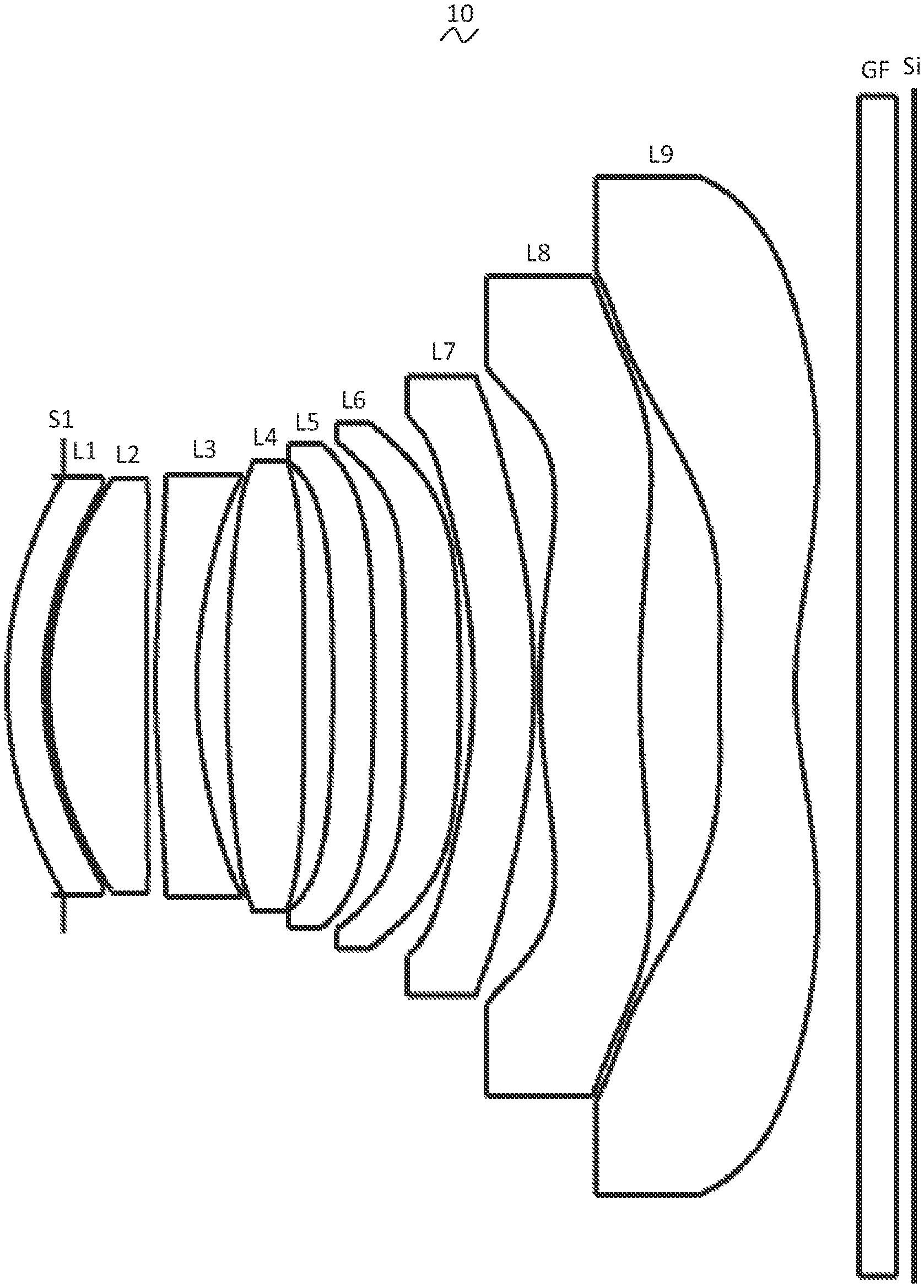
[0029] Referring to the accompanying drawings, the present disclosure provides a camera optical lens 10. FIG. 1 shows the camera optical lens 10 of the first embodiment of the present disclosure, and the camera optical lens 10 includes nine lenses. Specifically, the camera optical lens 10 includes, from an object side to an image side: an aperture S1, a first lens L1, a second lens L2, a third lens L3, a fourth lens L4, a fifth lens L5, a sixth lens L6, a seventh lens L7, an eighth lens L8 and an ninth lens L9. An optical element, such as an optical filter GF, may be arranged between the ninth lens L9 and an image surface Si.
[0030] In this embodiment, the first lens L1 has a negative refractive power, the second lens L2 has a positive refractive power, the third lens L3 has a negative refractive power, the fourth lens L4 has a positive refractive power, the fifth lens L5 has a negative refractive power, the sixth lens L6 has a positive refractive power, the seventh lens L7 has a negative refractive power, the eighth lens L8 has a positive refractive power, and the ninth lens L9 has a negative refractive power. It can be understood that, in other embodiments, the first lens L1, the third lens L3, the fourth lens L4, the fifth lens L5, the sixth lens L6, the seventh lens L7, the eighth lens L8, and the ninth lens L9 may also have other refractive powers. In this embodiment, the second lens L2 has a positive refractive power, conducing to improve the performance of the optical system.
[0031] In this embodiment, the first lens L1, the second lens L2, the third lens L3, the fourth lens L4, the fifth lens L5, the sixth lens L6, the seventh lens L7, the eighth lens L8, and the ninth lens L9 are all made of plastic material. In other embodiments, the lenses may also be made of other materials.
[0032] In this embodiment, a focal length of the camera optical lens 10 is defined as f, and a focal length of the first lens L1 is defined as f1. The camera optical lens 10 satisfies a condition of -5.00.ltoreq.f1/f.ltoreq.-2.00, which specifies a ratio between the focal length f1 of the first lens L1 and the focal length f of the camera optical lens 10, effectively balancing spherical aberration and field curvature amount of the camera optical lens 10 in this range.
[0033] An on-axis thickness of the seventh lens L7 is defined as d13, an on-axis distance from an image-side surface of the seventh lens L7 to an object-side surface of the eighth lens L8 is defined as d14, and the camera optical lens 10 further satisfies a condition of 2.50.ltoreq.d13/d14.ltoreq.10.00, which specifies a ratio between the on-axis thickness d13 of the seventh lens L7 and an on-axis distance d14 from an image-side surface of the seventh lens L7 to an object-side surface of the eighth lens L8, conducing to compress the total track length and achieve an ultra-thin effect in this range.
[0034] A central curvature radius of an object-side surface of the sixth lens L6 is defined as R11, a central curvature radius of an image-side surface of the sixth lens L6 is defined as R12, and the camera optical lens 10 further satisfies a condition of 2.50.ltoreq.R11/R12.ltoreq.6.50, which specifies a shape of the sixth lens L6. Within this range, the deflection of light passing through the lens can be eased and aberrations can be effectively reduced. Preferably, the camera optical lens 10 further satisfies a condition of 2.73.ltoreq.R11/R12.ltoreq.6.36.
[0035] In this embodiment, the object-side surface of the first lens L1 is convex in a paraxial region, and the image-side surface of the first lens L1 is concave in the paraxial region.
[0036] A central curvature radius of the object-side surface of the first lens L1 is defined as R1, a central curvature radius of the image-side surface of the first lens L1 is defined as R2, and the camera optical lens satisfies a condition of 2.49.ltoreq.(R1+R2)/(R1-R2).ltoreq.15.47, which reasonably controls a shape of the first lens L1, so that the first lens L1 can effectively correct system spherical aberration. Preferably, the camera optical lens 10 satisfies a condition of 3.98.ltoreq.(R1+R2)/(R1-R2).ltoreq.12.38.
[0037] An on-axis thickness of the first lens L1 is defined as d1, a total track length of the camera optical lens 10 is defined as TTL, and the camera optical lens 10 further satisfies a condition of 0.02.ltoreq.d1/TTL.ltoreq.0.06, conducing to realize an ultra-thin effect in this range. Preferably, the camera optical lens 10 further satisfies a condition of 0.03.ltoreq.d1/TTL.ltoreq.0.05.
[0038] In this embodiment, an object-side surface of the second lens L2 is convex in the paraxial region, and an image-side surface of the second lens L2 is concave in the paraxial region.
[0039] The focal length of the camera optical lens 10 is defined as f, a focal length of the second lens L2 is defined as f2, and the camera optical lens 10 further satisfies a condition of 0.35.ltoreq.f2/f.ltoreq.1.13. In this way, a positive refractive power of the second lens L2 is controlled within a reasonable range, so that it is beneficial to correct the aberration of the optical system. Preferably, the camera optical lens 10 further satisfies a condition of 0.56.ltoreq.f2/f.ltoreq.0.91.
[0040] A central curvature radius of the object-side surface of the second lens L2 is defined as R3, a central curvature radius of the image-side surface of the second lens L2 is defined as R4, and the camera optical lens 10 further satisfies a condition of -2.32.ltoreq.(R3+R4)/(R3-R4).ltoreq.-0.76, which specifies a shape of the second lens L2. Within this range, a development towards ultra-thin and wide-angle lenses would facilitate correcting the problem of an on-axis aberration. Preferably, the camera optical lens 10 further satisfies a condition of -1.45.ltoreq.(R3+R4)/(R3-R4).ltoreq.-0.95.
[0041] A total track length of the camera optical lens 10 is defined as TTL, an on-axis thickness of the second lens L2 is defined as d3, and the camera optical lens 10 satisfies a condition of 0.05.ltoreq.d3/TTL.ltoreq.0.16. Within this range, it is beneficial to achieve ultra-thin lenses. Preferably, the camera optical lens 10 further satisfies a condition of 0.08.ltoreq.d3/TTL.ltoreq.0.13.
[0042] In an embodiment, an object-side surface of the third lens L3 is convex in the paraxial region, and an image-side surface of the third lens L3 is concave in the paraxial region.
[0043] The focal length of the camera optical lens 10 is defined as f, a focal length of the third lens L3 is defined as f3, and the camera optical lens 10 further satisfies a condition of -3.29.ltoreq.f3/f.ltoreq.-1.04. In this way, a refractive power is distributed appropriately, so that the camera optical lens can attain a better imaging quality and a lower sensitivity. Preferably, the camera optical lens 10 further satisfies a condition of -2.05.ltoreq.f3/f.ltoreq.-1.30.
[0044] A central curvature radius of the object-side surface of the third lens L3 is defined as R5, a central curvature radius of the image-side surface of the third lens L3 is defined as R6, and the camera optical lens 10 further satisfies a condition of 1.57.ltoreq.(R5+R6)/(R5-R6).ltoreq.5.06, which specifies a shape of the third lens L3. Within this range, the deflection of light passing through the lens can be eased and aberrations can be effectively reduced. Preferably, the camera optical lens 10 further satisfies a condition of 2.52.ltoreq.(R5+R6)/(R5-R6).ltoreq.4.05.
[0045] The total track length of the camera optical lens 10 is defined as TTL, an on-axis thickness of the third lens L3 is defined as d5, and the camera optical lens 10 further satisfies a condition of 0.02.ltoreq.d5/TTL.ltoreq.0.09. This can facilitate achieving ultra-thin lenses. Preferably, the camera optical lens 10 further satisfies a condition of 0.04.ltoreq.d5/TTL.ltoreq.0.07.
[0046] In an embodiment, an object-side surface of the fourth lens L4 is convex in the paraxial region, and an image-side surface of the fourth lens L4 is convex in the paraxial region.
[0047] The focal length of the camera optical lens 10 is defined as f, a focal length of the fourth lens L4 is defined as f4, and the camera optical lens 10 further satisfies a condition of 0.88.ltoreq.f4/f.ltoreq.2.87. In this way, a refractive power is distributed appropriately, so that the camera optical lens can attain a better imaging quality and a lower sensitivity. Preferably, the camera optical lens 10 further satisfies a condition of 1.41.ltoreq.f4/f.ltoreq.2.30.
[0048] A central curvature radius of an object-side surface of the fourth lens L4 is defined as R7, a central curvature radius of an image-side surface of the fourth lens L4 is defined as R8, and the camera optical lens 10 further satisfies a condition of -1.49.ltoreq.(R7+R8)/(R7-R8).ltoreq.-0.45, which specifies a shape of the fourth lens L4. Within this range, a development towards ultra-thin and wide-angle lens would facilitate correcting problems such as an off-axis aberration. Preferably, the camera optical lens 10 further satisfies a condition of -0.93.ltoreq.(R7+R8)/(R7-R8).ltoreq.-0.57.
[0049] The total track length of the camera optical lens 10 is defined as TTL, an on-axis thickness of the fourth lens L4 is defined as d7, and the camera optical lens 10 further satisfies a condition of 0.04.ltoreq.d7/TTL.ltoreq.0.14. Within this range, this can facilitate achieving ultra-thin lenses. Preferably, the camera optical lens 10 further satisfies a condition of 0.07.ltoreq.d7/TTL.ltoreq.0.11.
[0050] In an embodiment, an object-side surface of the fifth lens L5 is concave in the paraxial region, and an image-side surface of the fifth lens L5 is convex in the paraxial region.
[0051] The focal length of the camera optical lens 10 is defined as f, a focal length of the fifth lens L5 is defined as f5, and the camera optical lens 10 further satisfies a condition of -163.02.ltoreq.f5/f.ltoreq.664.49, which can effectively make a light angle of the camera optical lens 10 gentle and reduce a tolerance sensitivity. Preferably, the camera optical lens 10 further satisfies a condition of -101.89.ltoreq.f5/f.ltoreq.531.59.
[0052] A central curvature radius of the object-side surface of the fifth lens L5 is defined as R9, a central curvature radius of the image-side surface of the fifth lens L5 is defined as R10, and the camera optical lens 10 further satisfies a condition of -54.65.ltoreq.(R9+R10)/(R9-R10).ltoreq.622.16, which specifies a shape of the fifth lens L5. Within this range, a development towards ultra-thin and wide-angle lenses can facilitate correcting a problem of the off-axis aberration. Preferably, the camera optical lens 10 further satisfies a condition of -34.15.ltoreq.(R9+R10)/(R9-R10).ltoreq.497.73.
[0053] The total track length of the camera optical lens 10 is defined as TTL, an on-axis thickness of the fifth lens L5 is defined as d9, and the camera optical lens 10 further satisfies a condition of 0.02.ltoreq.d9/TTL.ltoreq.0.08. Within this range, this can facilitate achieving ultra-thin lenses. Preferably, the camera optical lens 10 further satisfies a condition of 0.03.ltoreq.d9/TTL.ltoreq.0.06.
[0054] In an embodiment, an object-side surface of the sixth lens L6 is concave in the paraxial region, and an image-side surface of the sixth lens L6 is convex in the paraxial region.
[0055] A focal length of the camera optical lens 10 is defined as f, a focal length of the sixth lens L6 is defined as f6, and the camera optical lens satisfies a condition of 3.18.ltoreq.f6/f.ltoreq.11.86. In this way, a refractive power is distributed appropriately, so that the camera optical lens can attain a better imaging quality and a lower sensitivity. Preferably, the camera optical lens 10 further satisfies a condition of 5.09.ltoreq.f6/f.ltoreq.9.49.
[0056] A central curvature radius of the object-side surface of the sixth lens L6 is defined as R11, a central curvature radius of the image-side surface of the sixth lens L6 is defined as R12, and the camera optical lens 10 further satisfies a condition of 0.69.ltoreq.(R11+R12)/(R11-R12).ltoreq.3.03, which specifies a shape of the sixth lens L6. Within this range, a development towards ultra-thin and wide-angle lenses would facilitate correcting a problem like the off-axis aberration. Preferably, the camera optical lens 10 further satisfies a condition of 1.11.ltoreq.(R11+R12)/(R11-R12).ltoreq.2.42.
[0057] The total track length of the camera optical lens 10 is defined as TTL, an on-axis thickness of the sixth lens L6 is defined as d11, and the camera optical lens 10 further satisfies a condition of 0.03.ltoreq.d11/TTL.ltoreq.0.10. Within this range, this can facilitate achieving ultra-thin lenses. Preferably, the camera optical lens 10 further satisfies a condition of 0.05.ltoreq.d11/TTL.ltoreq.0.08.
[0058] In an embodiment, an object-side surface of the seventh lens L7 is concave in the paraxial region, and an image-side surface of the seventh lens L7 is convex in the paraxial region.
[0059] The focal length of the camera optical lens 10 is defined as f, a focal length of seventh lens L7 is defined as f7, and the camera optical lens 10 further satisfies a condition of -10.88.ltoreq.f7/f.ltoreq.-3.51. Within this range, a refractive power is distributed appropriately, so that the system can attain the better imaging quality and lower sensitivity. Preferably, the camera optical lens 10 further satisfies a condition of -6.80.ltoreq.f7/f.ltoreq.-4.39.
[0060] A central curvature radius of the object-side surface of the seventh lens L7 is defined as R13, a central curvature radius of the image-side surface of the seventh lens L7 is defined as R14, and the camera optical lens 10 further satisfies a condition of -15.70.ltoreq.(R13+R14)/(R13-R14).ltoreq.-4.97, which specifies a shape of the seventh lens L7. Within this specified range, the deflection of light passing through the lens can be eased and aberrations can be effectively reduced. Preferably, the camera optical lens 10 further satisfies a condition of -9.81.ltoreq.(R13+R14)/(R13-R14).ltoreq.-6.21.
[0061] The total track length of the camera optical lens 10 is defined as TTL, an on-axis thickness of the seventh lens L7 is defined as d13, and the camera optical lens 10 further satisfies a condition of 0.02.ltoreq.d13/TTL.ltoreq.0.10. Within this range, it is beneficial to achieve ultra-thin lenses. Preferably, the camera optical lens 10 further satisfies a condition of 0.03.ltoreq.d13/TTL.ltoreq.0.08.
[0062] In an embodiment, an object-side surface of the eighth lens L8 is convex in the paraxial region, and an image-side surface of eighth lens L8 is concave in the paraxial region.
[0063] The focal length of the camera optical lens 10 is defined as f, a focal length of eighth lens L8 is defined as f8, and the camera optical lens 10 further satisfies a condition of 1.05.ltoreq.f8/f.ltoreq.3.63. In this way, a refractive power is distributed appropriately, so that the camera optical lens can attain a better imaging quality and a lower sensitivity. Preferably, the camera optical lens 10 further satisfies a condition of 1.68.ltoreq.f8/f.ltoreq.2.90.
[0064] A central curvature radius of the object-side surface of the eighth lens L8 is defined as R15, a central curvature radius of the image-side surface of the sixth lens L8 is defined as R16, and the camera optical lens 10 further satisfies a condition of -7.36.ltoreq.(R15+R16)/(R15-R16).ltoreq.-2.36, which specifies a shape of the eighth lens L8. Within this range, a development towards ultra-thin and wide-angle lenses would facilitate correcting a problem like the off-axis aberration. Preferably, the camera optical lens 10 further satisfies a condition of -4.60.ltoreq.(R15+R16)/(R15-R16).ltoreq.-2.95.
[0065] The total track length of the camera optical lens 10 is defined as TTL, an on-axis thickness of the eighth lens L8 is defined as d15, and the camera optical lens 10 further satisfies a condition of 0.06.ltoreq.d15/TTL.ltoreq.0.19. Within this range, this can facilitate achieving ultra-thin lenses. Preferably, the camera optical lens 10 further satisfies a condition of 0.09.ltoreq.d15/TTL.ltoreq.0.15.
[0066] In an embodiment, an object-side surface of the ninth lens L9 is convex in the paraxial region, and an image-side surface of ninth lens L9 is concave in the paraxial region.
[0067] The focal length of the camera optical lens 10 is defined as f, a focal length of the ninth lens L9 is defined as f9, and the camera optical lens 10 further satisfies a condition of -2.28.ltoreq.f9/f.ltoreq.-0.70. In this way, a refractive power is distributed appropriately, so that the camera optical lens can attain a better imaging quality and a lower sensitivity. Preferably, the camera optical lens 10 further satisfies a condition of -1.43.ltoreq.f9/f.ltoreq.-0.87.
[0068] A central curvature radius of the object-side surface of the ninth lens L9 is defined as R17, a central curvature radius of the image-side surface of the ninth lens L9 is defined as R18, and the camera optical lens 10 further satisfies a condition of 0.77.ltoreq.(R17+R18)/(R17-R18).ltoreq.2.90, which specifies a shape of the ninth lens L9. Within this range, a development towards ultra-thin and wide-angle lenses would facilitate correcting a problem like the off-axis aberration. Preferably, the camera optical lens 10 further satisfies a condition of 1.23.ltoreq.(R17+R18)/(R17-R18).ltoreq.2.32.
[0069] The total track length of the camera optical lens 10 is defined as TTL, an on-axis thickness of the ninth lens L9 is defined as d17, and the camera optical lens 10 further satisfies a condition of 0.04.ltoreq.d17/TTL.ltoreq.0.13. Within this range, this can facilitate achieving ultra-thin lenses. Preferably, the camera optical lens 10 further satisfies a condition of 0.06.ltoreq.d17/TTL.ltoreq.0.10.
[0070] In an embodiment, an image height of the camera optical lens 10 is defined as IH, the total track length of the camera optical lens 10 is defined as TTL, and the camera optical lens 10 further satisfies a condition of TTL/IH.ltoreq.1.77, thus facilitating to achieve ultra-thin lenses.
[0071] In an embodiment, an FOV (field of view) of the camera optical lens 10 is greater than or equal to 72.00.degree., thereby achieving a wide-angle and a better imaging performance of the camera optical lens 10.
[0072] In an embodiment, an aperture value FNO of the camera optical lens 10 is less than or equal to 1.91, thereby achieving large apertures, and a better imaging performance of the camera optical lens 10.
[0073] It can be understood that, in other embodiments, for the first lens L1, the second lens L2, the third lens L3, the fourth lens L4, the fifth lens L5, the sixth lens L6, the seventh lens L7, the eighth lens L8, and the ninth lens L9, surface profiles of an object-side surface and an image-side surface respectively may be configured in other convex or concave arrangement.
[0074] When the above condition is satisfied, the camera optical lens 10 can meet the design requirements of large apertures, wide-angle and ultra-thin in the case that a good optical performance is maintained. According to characteristics of the camera optical lens 10, the camera optical lens 10 is particularly suitable for mobile phone camera lens components and WEB camera lenses composed of camera elements such as CCD and CMOS with high pixel.
[0075] In the following, examples will be used to describe the camera optical lens 10 of the present disclosure. The symbols recorded in each example will be described as follows. The focal length, on-axis distance, central curvature radius, on-axis thickness, inflexion point position, and arrest point position are all in units of mm.
[0076] TTL refers to a total track length (an on-axis distance from an object-side surface of the first lens L1 to an image surface Si) in units of mm.
[0077] Aperture value FNO refers to a ratio of an effective focal length of the camera optical lens to an entrance pupil diameter.
[0078] Preferably, inflexion points and/or arrest points can be arranged on the object-side surface and/or the image-side surface of the lens, so as to satisfy the demand for high quality imaging. The description below may be referred for specific implementations.
[0079] The design data of the camera optical lens 10 in the first embodiment of the present disclosure are shown in Table 1 and Table 2.
TABLE-US-00001 TABLE 1 R d nd vd S1 .infin. d0= -0.313 R1 1.748 d1= 0.202 nd1 1.5440 v1 55.90 R2 1.439 d2= 0.029 R3 1.510 d3= 0.543 nd2 1.5440 v2 55.90 R4 22.547 d4= 0.047 R5 3.454 d5= 0.228 nd3 1.6390 v3 23.50 R6 1.789 d6= 0.166 R7 4.815 d7= 0.428 nd4 1.5440 v4 55.90 R8 -25.270 d8= 0.158 R9 -10.623 d9= 0.226 nd5 1.5440 v5 55.90 R10 -11.639 d10= 0.171 R11 -33.130 d11= 0.305 nd6 1.5440 v6 55.90 R12 -11.176 d12= 0.076 R13 -2.571 d13= 0.333 nd7 1.6390 v7 23.50 R14 -3.33 d14= 0.034 R15 2.491 d15= 0.554 nd8 1.5440 v8 55.90 R16 4.457 d16= 0.438 R17 8.036 d17= 0.419 nd9 1.5350 v9 55.70 R18 1.69 d18= 0.350 R19 .infin. d19= 0.210 ndg 1.5170 vg 64.20 R20 .infin. d20= 0.099
[0080] In the table, meanings of various symbols will be described as follows:
[0081] S1: aperture;
[0082] R: curvature radius at a center of an optical surface;
[0083] R1: central curvature radius of the object-side surface of the first lens L1;
[0084] R2: central curvature radius of the image-side surface of the first lens L1;
[0085] R3: central curvature radius of the object-side surface of the second lens L2;
[0086] R4: central curvature radius of the image-side surface of the second lens L2;
[0087] R5: central curvature radius of the object-side surface of the third lens L3;
[0088] R6: central curvature radius of the image-side surface of the third lens L3;
[0089] R7: central curvature radius of the object-side surface of the fourth lens L4;
[0090] R8: central curvature radius of the image-side surface of the fourth lens L4;
[0091] R9: central curvature radius of the object-side surface of the fifth lens L5;
[0092] R10: central curvature radius of the image-side surface of the fifth lens L5;
[0093] R11: central curvature radius of the object-side surface of the sixth lens L6;
[0094] R12: central curvature radius of the image-side surface of the sixth lens L6;
[0095] R13: central curvature radius of the object-side surface of the seventh lens L7;
[0096] R14: central curvature radius of the image-side surface of the seventh lens L7;
[0097] R15: central curvature radius of the object-side surface of the eighth lens L8;
[0098] R16: central curvature radius of the image-side surface of the eighth lens L8;
[0099] R17: central curvature radius of the object-side surface of the ninth lens L9;
[0100] R18: central curvature radius of the image-side surface of the ninth lens L9;
[0101] R19: central curvature radius of an object-side surface of the optical filter GF;
[0102] R20: central curvature radius of an image-side surface of the optical filter GF;
[0103] d: on-axis thickness of a lens, or an on-axis distance between lenses;
[0104] d0: on-axis distance from the aperture S1 to the object-side surface of the first lens L1;
[0105] d1: on-axis thickness of the first lens L1;
[0106] d2: on-axis distance from the image-side surface of the first lens L1 to the object-side surface of the second lens L2;
[0107] d3: on-axis thickness of the second lens L2;
[0108] d4: on-axis distance from the image-side surface of the second lens L2 to the object-side surface of the third lens L3;
[0109] d5: on-axis thickness of the third lens L3;
[0110] d6: on-axis distance from the image-side surface of the third lens L3 to the object-side surface of the fourth lens L4;
[0111] d7: on-axis thickness of the fourth lens L4;
[0112] d8: on-axis distance from the image-side surface of the fourth lens L4 to the object-side surface of the fifth lens L5;
[0113] d9: on-axis thickness of the fifth lens L5;
[0114] d10: on-axis distance from the image-side surface of the fifth lens L5 to the object-side surface of the sixth lens L6;
[0115] d11: on-axis thickness of the sixth lens L6;
[0116] d12: on-axis distance from the image-side surface of the sixth lens L6 to the object-side surface of the seventh lens L7;
[0117] d13: on-axis thickness of the seventh lens L7;
[0118] d14: on-axis distance from the image-side surface of the seventh lens L7 to the object-side surface of the eighth lens L8;
[0119] d15: on-axis thickness of the seventh lens L8;
[0120] d16: on-axis distance from the image-side surface of the eighth lens L8 to the object-side surface of the ninth lens L9;
[0121] d17: on-axis thickness of the ninth lens L9;
[0122] d18: on-axis distance from the image-side surface of the ninth lens L9 to the object-side surface of the optical filter GF;
[0123] d19: on-axis thickness of the optical filter GF;
[0124] d20: on-axis distance from the image-side surface of the optical filter GF to the image surface Si;
[0125] nd: refractive index of a d line;
[0126] nd1: refractive index of the d line of the first lens L1;
[0127] nd2: refractive index of the d line of the second lens L2;
[0128] nd3: refractive index of the d line of the third lens L3;
[0129] nd4: refractive index of the d line of the fourth lens L4;
[0130] nd5: refractive index of the d line of the fifth lens L5;
[0131] nd6: refractive index of the d line of the sixth lens L6;
[0132] nd7: refractive index of the d line of the seventh lens L7;
[0133] nd8: refractive index of the d line of the eighth lens L8;
[0134] nd9: refractive index of the d line of the ninth lens L9;
[0135] ndg: refractive index of the d line of the optical filter GF;
[0136] vd: abbe number;
[0137] v1: abbe number of the first lens L1;
[0138] v2: abbe number of the second lens L2;
[0139] v3: abbe number of the third lens L3;
[0140] v4: abbe number of the fourth lens L4;
[0141] v5: abbe number of the fifth lens L5;
[0142] v6: abbe number of the sixth lens L6;
[0143] v7: abbe number of the seventh lens L7;
[0144] v8: abbe number of the eighth lens L8;
[0145] v9: abbe number of the ninth lens L9;
[0146] vg: abbe number of the optical filter GF.
[0147] Table 2 shows aspherical surface data of the camera optical lens 10 in the first embodiment of the present disclosure.
TABLE-US-00002 TABLE 2 Conic coefficient Aspheric surface coefficients k A4 A6 A8 A10 A12 R1 -8.0064E-02 -5.8836E-03 -2.4711E-02 5.2026E-02 -6.5260E-02 4.4161E-02 R2 -3.6131E-01 -2.5941E-02 -9.2054E-03 -5.2222E-03 2.4631E-04 4.9127E-03 R3 -1.5938E-01 -1.2659E-02 -9.4994E-03 -2.3071E-03 7.3474E-04 1.0616E-03 R4 1.8758E+02 -1.2067E-01 3.5659E-01 -5.0019E-01 3.7422E-01 -1.5569E-01 R5 -4.6110E+01 -1.5901E-01 3.9381E-01 -5.2132E-01 3.7235E-01 -1.4791E-01 R6 -1.5570E+01 1.1323E-01 -2.3058E-01 4.7282E-01 -5.4620E-01 3.2930E-01 R7 -4.7838E+00 -6.0823E-03 -1.9613E-02 3.4107E-02 -2.8252E-02 3.0560E-02 R8 4.8734E+02 -9.7748E-03 -3.2182E-02 3.7837E-03 -4.5516E-04 3.6338E-03 R9 9.0669E+01 -5.1694E-02 1.8837E-03 -1.8048E-02 -6.9025E-03 -2.6670E-03 R10 7.7114E+01 -4.7355E-02 -2.0001E-02 5.3041E-03 -1.1477E-02 -4.6245E-03 R11 -6.5652E+03 -6.3612E-02 -6.3344E-02 -3.0501E-02 3.5393E-03 1.5097E-03 R12 7.2417E+01 -1.3624E-01 1.0389E-01 -1.2664E-01 -1.2461E-01 3.0940E-01 R13 6.5606E-01 -1.5769E-02 2.3163E-01 -4.2989E-01 3.9730E-01 -1.7417E-01 R14 -3.7412E+01 -1.4900E-01 2.5630E-01 -3.0543E-01 2.1760E-01 -8.0413E-02 R15 -1.2535E+01 -6.2328E-02 4.8671E-02 -9.6789E-02 5.2489E-02 -1.5773E-02 R16 -3.6678E+01 -1.7602E-02 9.8385E-03 -2.5881E-02 1.1269E-02 -1.7364E-03 R17 -1.4856E+01 -3.4168E-01 1.8690E-01 -5.8616E-02 1.3553E-02 -2.2717E-03 R18 -3.2686E+00 -2.3348E-01 1.5840E-01 -7.4792E-02 2.2822E-02 -4.1802E-03 Conic coefficient Aspheric surface coefficients k A14 A16 A18 A20 R1 -8.0064E-02 -1.2017E-02 1.8918E-04 0.0000E+00 0.0000E+00 R2 -3.6131E-01 4.6166E-03 -1.2280E-03 0.0000E+00 0.0000E+00 R3 -1.5938E-01 3.5343E-04 2.2093E-04 0.0000E+00 0.0000E+00 R4 1.8758E+02 2.3409E-02 2.7739E-03 0.0000E+00 0.0000E+00 R5 -4.6110E+01 3.0621E-02 -1.7344E-03 0.0000E+00 0.0000E+00 R6 -1.5570E+01 -5.8454E-02 -1.0271E-02 0.0000E+00 0.0000E+00 R7 -4.7838E+00 -5.1094E-03 5.2875E-04 0.0000E+00 0.0000E+00 R8 4.8734E+02 2.0718E-04 -1.8453E-03 0.0000E+00 0.0000E+00 R9 9.0669E+01 -1.6381E-03 -1.1040E-03 0.0000E+00 0.0000E+00 R10 7.7114E+01 -7.1141E-04 1.9341E-03 0.0000E+00 0.0000E+00 R11 -6.5652E+03 1.7324E-03 1.1516E-03 0.0000E+00 0.0000E+00 R12 7.2417E+01 -2.0435E-01 4.6563E-02 0.0000E+00 0.0000E+00 R13 6.5606E-01 2.4607E-02 1.1562E-03 0.0000E+00 0.0000E+00 R14 -3.7412E+01 1.1723E-02 -2.6436E-05 0.0000E+00 0.0000E+00 R15 -1.2535E+01 2.8711E-03 -1.4645E-04 0.0000E+00 0.0000E+00 R16 -3.6678E+01 8.1882E-05 2.3007E-07 0.0000E+00 0.0000E+00 R17 -1.4856E+01 2.2987E-04 -1.0730E-05 0.0000E+00 0.0000E+00 R18 -3.2686E+00 4.1402E-04 -1.7088E-05 0.0000E+00 0.0000E+00
[0148] Here, K is a conic coefficient, and A4, A6, A8, A10, A12, A14, A16, A18 and A20 are aspheric surface coefficients.
y=(x.sup.2/R)/{1+[1-(k+1)(x.sup.2/R.sup.2)].sup.1/2}+A4x.sup.4+A6x.sup.6- +A8x.sup.8+A10x.sup.10+A12x.sup.12+A14x.sup.14+A16x.sup.16+A18x.sup.18+A20- x.sup.20 (1)
[0149] Here, x denotes a vertical distance between a point on an aspheric curve and an optical axis, and y denotes a depth of a aspheric surface (i.e. a vertical distance between a point on an aspheric surface that is x away from the optical axis, and a tangent plane tangent to an vertex of the optical axis on the aspheric surface).
[0150] For convenience, an aspheric surface of each lens surface uses the aspheric surfaces shown in the above formula (1). However, the present disclosure is not limited to the aspherical polynomials form shown in the formula (1).
[0151] Table 3 and Table 4 show design data of inflexion points and arrest points of the camera optical lens 10 according to the first embodiment of the present disclosure. P1R1 and P1R2 respectively represent the object-side surface and the image-side surface of the first lens L1, P2R1 and P2R2 respectively represent the object-side surface and the image-side surface of the second lens L2, P3R1 and P3R2 respectively represent the object-side surface and the image-side surface of the third lens L3, P4R1 and P4R2 respectively represent the object-side surface and the image-side surface of the fourth lens L4, P5R1 and P5R2 respectively represent the object-side surface and the image-side surface of the fifth lens L5, P6R1 and P6R2 respectively represent the object-side surface and the image-side surface of the sixth lens L6, P7R1 and P7R2 respectively represent the object-side surface and the image-side surface of the seventh lens L7. P8R1 and P8R2 respectively represent the object-side surface and the image-side surface of the eighth lens L8, P9R1 and P9R2 respectively represent the object-side surface and the image-side surface of the ninth lens L9. The data in the column named "inflexion point position" refer to vertical distances from inflexion points arranged on each lens surface to the optic axis of the camera optical lens 10. The data in the column named "arrest point position" refer to vertical distances from arrest points arranged on each lens surface to the optical axis of the camera optical lens 10.
TABLE-US-00003 TABLE 3 Number(s) of Inflexion point Inflexion point Inflexion point inflexion points position 1 position 2 position 3 P1R1 0 / / / P1R2 0 / / / P2R1 0 / / / P2R2 3 0.215 0.415 0.765 P3R1 1 0.665 / / P3R2 0 / / / P4R1 0 / / / P4R2 0 / / / P5R1 0 / / / P5R2 0 / / / P6R1 0 / / / P6R2 2 1.245 1.275 / P7R1 0 / / / P7R2 1 1.425 / / P8R1 2 0.555 1.455 / P8R2 3 0.625 1.665 1.915 P9R1 3 0.185 1.305 1.815 P9R2 1 0.495 / /
TABLE-US-00004 TABLE 4 Number(s) of arrest points Arrest point position 1 P1R1 0 / P1R2 0 / P2R1 0 / P2R2 1 0.905 P3R1 0 / P3R2 0 / P4R1 0 / P4R2 0 / P5R1 0 / P5R2 0 / P6R1 0 / P6R2 0 / P7R1 0 / P7R2 1 1.535 P8R1 1 0.905 P8R2 1 1.015 P9R1 1 0.315 P9R2 1 1.105
[0152] FIG. 2 and FIG. 3 illustrate a longitudinal aberration and a lateral color of light with wavelengths of 656 nm, 587 nm, 546 nm, 486 nm and 436 nm after passing the camera optical lens 10 according to the first embodiment, respectively. FIG. 4 illustrates a field curvature and a distortion of light with a wavelength of 546 nm after passing the camera optical lens 10 according to the first embodiment. In FIG. 4, a field curvature S is a field curvature in a sagittal direction, and T is a field curvature in a meridional direction.
[0153] Table 13 in the following shows various values of first, second and third embodiments and values corresponding to parameters which are specified in the above conditions.
[0154] As shown in Table 13, the first embodiment satisfies the above conditions.
[0155] In this Embodiment, an entrance pupil diameter (ENPD) of the camera optical lens is 2.045 mm, an image height (IH) of 1.0H is 2.900 mm, and a field of view (FOV) in a diagonal direction is 72.00.degree.. Thus, the camera optical lens meets the design requirements of a large aperture, wide-angle and ultra-thin. Its on-axis and off-axis aberrations are fully corrected, thereby achieving excellent optical characteristics.
Second Embodiment
[0156] FIG. 5 shows a camera optical lens 20 of the second embodiment of the present disclosure, the second embodiment is basically the same as the first embodiment and involves symbols having the same meanings as the first embodiment.
[0157] Table 5 and Table 6 show design data of the camera optical lens 20 in the second embodiment of the present disclosure.
TABLE-US-00005 TABLE 5 R d nd vd S1 .infin. d0= -0.297 R1 1.831 d1= 0.202 nd1 1.5440 v1 55.90 R2 1.400 d2= 0.030 R3 1.472 d3= 0.515 nd2 1.5440 v2 55.90 R4 19.898 d4= 0.055 R5 3.344 d5= 0.264 nd3 1.6390 v3 23.50 R6 1.773 d6= 0.144 R7 4.661 d7= 0.484 nd4 1.5440 v4 55.90 R8 -25.659 d8= 0.150 R9 -10.753 d9= 0.273 nd5 1.5440 v5 55.90 R10 -11.570 d10= 0.174 R11 -38.571 d11= 0.322 nd6 1.5440 v6 55.90 R12 -11.282 d12= 0.083 R13 -2.647 d13= 0.220 nd7 1.6390 v7 23.50 R14 -3.42 d14= 0.043 R15 2.403 d15= 0.616 nd8 1.5440 v8 55.90 R16 4.271 d16= 0.436 R17 6.696 d17= 0.419 nd9 1.5350 v9 55.70 R18 1.647 d18= 0.350 R19 .infin. d19= 0.210 ndg 1.5170 vg 64.20 R20 .infin. d20= 0.092
[0158] Table 6 shows aspherical surface data of each lens of the camera optical lens 20 in the second embodiment of the present disclosure.
TABLE-US-00006 TABLE 6 Conic coefficient Aspheric surface coefficients k A4 A6 A8 A10 A12 R1 -1.5808E-01 -1.1222E-02 -1.9743E-02 5.6408E-02 -6.3535E-02 4.3193E-02 R2 -6.0168E-01 -4.4107E-02 -1.2365E-02 -2.4075E-03 5.2116E-03 1.0662E-02 R3 -2.7275E-01 -2.3651E-02 -1.5823E-02 -2.4582E-03 3.3604E-03 3.8679E-03 R4 3.3448E+02 -1.1749E-01 3.5763E-01 -5.0320E-01 3.7157E-01 -1.5573E-01 R5 -4.1773E+01 -1.6324E-01 3.8341E-01 -5.2645E-01 3.7252E-01 -1.4518E-01 R6 -1.5131E+01 9.8608E-02 -2.3827E-01 4.6794E-01 -5.4874E-01 3.2861E-01 R7 -7.5698E+00 -9.7336E-03 -2.3412E-02 3.3890E-02 -2.7703E-02 3.0701E-02 R8 4.6875E+02 -6.1782E-03 -3.8336E-02 5.5416E-03 2.7125E-03 4.6707E-03 R9 8.9031E+01 -4.0085E-02 1.8497E-02 -1.5709E-02 -6.1288E-03 -2.9461E-03 R10 8.2936E+01 -4.6678E-02 -4.5625E-03 1.0825E-02 -1.2162E-02 -5.2430E-03 R11 -1.8398E+04 -3.4245E-02 -5.6962E-02 -3.0238E-02 3.3930E-03 1.8507E-03 R12 7.0458E+01 -1.1580E-01 1.0323E-01 -1.2717E-01 -1.2329E-01 3.1046E-01 R13 1.1627E+00 -2.7844E-02 2.3511E-01 -4.2621E-01 3.9831E-01 -1.7397E-01 R14 -3.1975E+01 -1.4553E-01 2.5575E-01 -3.0537E-01 2.1777E-01 -8.0348E-02 R15 -1.5183E+01 -6.0073E-02 4.9964E-02 -9.7015E-02 5.2313E-02 -1.5807E-02 R16 -4.0267E+01 -1.7112E-02 1.1966E-02 -2.5926E-02 1.1171E-02 -1.7463E-03 R17 -5.3612E+00 -3.4608E-01 1.8601E-01 -5.8470E-02 1.3615E-02 -2.2577E-03 R18 -2.8152E+00 -2.4102E-01 1.5843E-01 -7.4356E-02 2.2805E-02 -4.1899E-03 Conic coefficient Aspheric surface coefficients k A14 A16 A18 A20 R1 -1.5808E-01 -1.3272E-02 1.1569E-03 0.0000E+00 0.0000E+00 R2 -6.0168E-01 7.5511E-03 -7.4303E-03 0.0000E+00 0.0000E+00 R3 -2.7275E-01 2.1599E-03 8.9408E-04 0.0000E+00 0.0000E+00 R4 3.3448E+02 2.6252E-02 7.7708E-03 0.0000E+00 0.0000E+00 R5 -4.1773E+01 3.2962E-02 -1.1045E-03 0.0000E+00 0.0000E+00 R6 -1.5131E+01 -5.7347E-02 -8.3229E-03 0.0000E+00 0.0000E+00 R7 -7.5698E+00 -5.1594E-03 3.0602E-04 0.0000E+00 0.0000E+00 R8 4.6875E+02 -2.0306E-04 -2.8753E-03 0.0000E+00 0.0000E+00 R9 8.9031E+01 -1.5183E-03 1.8159E-04 0.0000E+00 0.0000E+00 R10 8.2936E+01 -3.5160E-04 2.0405E-03 0.0000E+00 0.0000E+00 R11 -1.8398E+04 2.2296E-03 1.7756E-03 0.0000E+00 0.0000E+00 R12 7.0458E+01 -2.0413E-01 4.6259E-02 0.0000E+00 0.0000E+00 R13 1.1627E+00 2.4614E-02 9.9334E-04 0.0000E+00 0.0000E+00 R14 -3.1975E+01 1.1722E-02 -4.3726E-05 0.0000E+00 0.0000E+00 R15 -1.5183E+01 2.8776E-03 -1.3660E-04 0.0000E+00 0.0000E+00 R16 -4.0267E+01 8.2123E-05 1.1504E-06 0.0000E+00 0.0000E+00 R17 -5.3612E+00 2.3047E-04 -1.1241E-05 0.0000E+00 0.0000E+00 R18 -2.8152E+00 4.1311E-04 -1.6787E-05 0.0000E+00 0.0000E+00
[0159] Table 7 and table 8 show design data of inflexion points and arrest points of each lens of the camera optical lens 20 lens according to the second embodiment of the present disclosure.
TABLE-US-00007 TABLE 7 Number(s) of Inflexion point Inflexion point Inflexion point inflexion points position 1 position 2 position 3 P1R1 0 / / / P1R2 0 / / / P2R1 0 / / / P2R2 2 0.275 0.335 / P3R1 2 0.485 0.985 / P3R2 0 / / / P4R1 0 / / / P4R2 0 / / / P5R1 0 / / / P5R2 0 / / / P6R1 1 1.165 / / P6R2 1 1.215 / / P7R1 0 / / / P7R2 1 1.425 / / P8R1 2 0.545 1.445 / P8R2 3 0.635 1.665 1.945 P9R1 3 0.195 1.305 1.955 P9R2 1 0.505 / /
TABLE-US-00008 TABLE 8 Number of Arrest point Arrest point arrest points position 1 position 1 P1R1 0 / / P1R2 0 / / P2R1 0 / / P2R2 0 / / P3R1 2 0.965 0.985 P3R2 0 / / P4R1 0 / / P4R2 0 / / P5R1 0 / / P5R2 0 / / P6R1 0 / / P6R2 0 / / P7R1 0 / / P7R2 0 / / P8R1 1 0.905 / P8R2 1 1.035 / P9R1 1 0.345 / P9R2 1 1.095 /
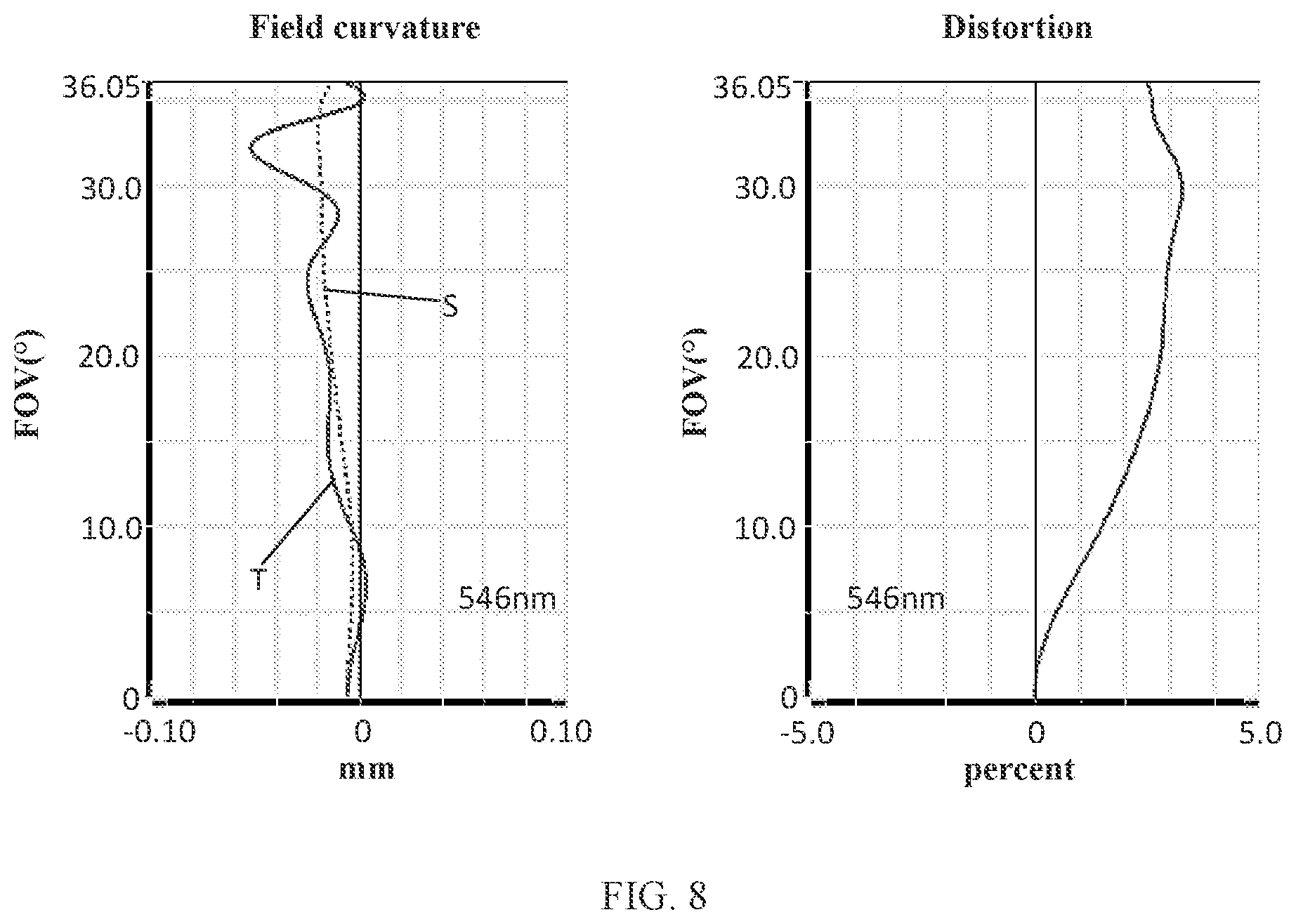
[0160] FIG. 6 and FIG. 7 illustrate a longitudinal aberration and a lateral color of light with wavelengths of 656 nm, 587 nm, 546 nm, 486 nm and 436 nm after passing the camera optical lens 20 according to the second embodiment. FIG. 8 illustrates a field curvature and a distortion of light with a wavelength of 546 nm after passing the camera optical lens 20 according to the second embodiment. A field curvature S in FIG. 8 is a field curvature in a sagittal direction, and T is a field curvature in a meridian direction.
[0161] As shown in Table 13, the second embodiment satisfies the above conditions.
[0162] In this embodiment, an entrance pupil diameter (ENPD) of the camera optical lens 20 is 2.040 mm, an image height (IH) of 1.0H is 2.900 mm, a field of view (FOV) in a diagonal direction is 72.10.degree.. Thus, the camera optical lens 20 meets the design requirements of large apertures, wide-angle and ultra-thin. Its on-axis and off-axis aberrations are fully corrected, thereby achieving excellent optical characteristics.
Third Embodiment
[0163] FIG. 9 shows a camera optical lens 30 of the third embodiment of the present disclosure, the third embodiment is basically the same as the first embodiment and involves symbols having the same meanings as the first embodiment, and only differences therebetween will be described in the following.
[0164] The fifth lens L5 has positive refractive power.
[0165] Table 9 and Table 10 show design data of the camera optical lens 30 in the embodiment of the present disclosure.
TABLE-US-00009 TABLE 9 R d nd vd S1 .infin. d0= -0.254 R1 1.909 d1= 0.202 nd1 1.5440 v1 55.90 R2 1.270 d2= 0.030 R3 1.395 d3= 0.493 nd2 1.5440 v2 55.90 R4 21.512 d4= 0.080 R5 3.174 d5= 0.304 nd3 1.6390 v3 23.50 R6 1.722 d6= 0.123 R7 4.242 d7= 0.471 nd4 1.5440 v4 55.90 R8 -28.773 d8= 0.137 R9 -11.018 d9= 0.215 nd5 1.5440 v5 55.90 R10 -10.965 d10= 0.255 R11 -70.374 d11= 0.290 nd6 1.5440 v6 55.90 R12 -11.312 d12= 0.078 R13 -2.957 d13= 0.178 nd7 1.6390 v7 23.50 R14 -3.874 d14= 0.071 R15 2.169 d15= 0.656 nd8 1.5440 v8 55.90 R16 3.787 d16= 0.405 R17 4.854 d17= 0.414 nd9 1.5350 v9 55.70 R18 1.546 d18= 0.350 R19 .infin. d19= 0.210 ndg 1.5170 vg 64.20 R20 .infin. d20= 0.170
[0166] Table 10 shows aspherical surface data of each lens of the camera optical lens 30 in the third embodiment of the present disclosure.
TABLE-US-00010 TABLE 10 Conic coefficient Aspheric surface coefficients k A4 A6 A8 A10 A12 R1 -8.9192E-01 -3.3076E-02 -5.7148E-03 5.8203E-02 -6.4426E-02 4.0032E-02 R2 -1.3744E+00 -8.5318E-02 -8.9234E-03 8.8930E-03 8.0630E-03 1.3673E-02 R3 -6.2759E-01 -5.4169E-02 -2.0904E-02 3.9442E-03 1.0916E-02 8.2600E-03 R4 4.0046E+02 -1.2422E-01 3.6580E-01 -5.0962E-01 3.6704E-01 -1.5289E-01 R5 -3.6778E+01 -1.7382E-01 3.7555E-01 -5.2767E-01 3.7335E-01 -1.4328E-01 R6 -1.4494E+01 8.3640E-02 -2.4447E-01 4.6550E-01 -5.5035E-01 3.2722E-01 R7 -7.5343E+00 -1.0485E-02 -2.5286E-02 3.2193E-02 -2.9217E-02 2.9511E-02 R8 3.8419E+02 1.2967E-02 -4.2387E-02 8.1330E-03 3.5860E-03 3.8206E-03 R9 8.6347E+01 -3.3779E-02 3.6413E-02 -1.5615E-02 -3.6827E-03 -9.6614E-04 R10 7.0174E+01 -5.5648E-02 6.5138E-03 1.8712E-02 -1.0831E-02 -4.6780E-03 R11 -9.5506E+04 -1.6982E-02 -5.7220E-02 -2.6235E-02 4.5410E-03 1.0991E-03 R12 6.9417E+01 -1.0924E-01 1.0618E-01 -1.3148E-01 -1.2490E-01 3.1111E-01 R13 1.6651E+00 -3.8758E-02 2.2197E-01 -4.2509E-01 3.9971E-01 -1.7434E-01 R14 -2.9231E+01 -1.4960E-01 2.5815E-01 -3.0956E-01 2.1575E-01 -7.9902E-02 R15 -1.5468E+01 -5.8015E-02 5.8168E-02 -9.8754E-02 5.2217E-02 -1.5611E-02 R16 -2.7433E+01 -1.4223E-02 1.6786E-02 -2.6261E-02 1.0920E-02 -1.7466E-03 R17 2.3000E+00 -3.3768E-01 1.8428E-01 -5.8640E-02 1.3522E-02 -2.2552E-03 R18 -2.9944E+00 -2.3445E-01 1.5595E-01 -7.4024E-02 2.2845E-02 -4.1894E-03 Conic coefficient Aspheric surface coefficients k A14 A16 A18 A20 R1 -8.9192E-01 -1.3731E-02 1.6965E-03 0.0000E+00 0.0000E+00 R2 -1.3744E+00 1.1602E-02 -1.9193E-02 0.0000E+00 0.0000E+00 R3 -6.2759E-01 2.3372E-03 -3.0459E-03 0.0000E+00 0.0000E+00 R4 4.0046E+02 3.1925E-02 1.3371E-02 0.0000E+00 0.0000E+00 R5 -3.6778E+01 3.5755E-02 7.1917E-04 0.0000E+00 0.0000E+00 R6 -1.4494E+01 -5.8093E-02 -8.2302E-03 0.0000E+00 0.0000E+00 R7 -7.5343E+00 -6.0871E-03 -5.9858E-04 0.0000E+00 0.0000E+00 R8 3.8419E+02 -1.3008E-03 -3.6133E-03 0.0000E+00 0.0000E+00 R9 8.6347E+01 -1.9589E-03 -9.7405E-04 0.0000E+00 0.0000E+00 R10 7.0174E+01 7.7195E-05 1.5011E-03 0.0000E+00 0.0000E+00 R11 -9.5506E+04 1.4283E-03 1.5313E-03 0.0000E+00 0.0000E+00 R12 6.9417E+01 -2.0360E-01 4.5909E-02 0.0000E+00 0.0000E+00 R13 1.6651E+00 2.4196E-02 1.4356E-03 0.0000E+00 0.0000E+00 R14 -2.9231E+01 1.2198E-02 -1.0132E-04 0.0000E+00 0.0000E+00 R15 -1.5468E+01 2.8853E-03 -1.8854E-04 0.0000E+00 0.0000E+00 R16 -2.7433E+01 8.7404E-05 1.5650E-06 0.0000E+00 0.0000E+00 R17 2.3000E+00 2.3590E-04 -1.1430E-05 0.0000E+00 0.0000E+00 R18 -2.9944E+00 4.1039E-04 -1.6505E-05 0.0000E+00 0.0000E+00
[0167] Table 11 and Table 12 show design data inflexion points and arrest points of the respective lenses in the camera optical lens 30 according to the third embodiment of the present disclosure.
TABLE-US-00011 TABLE 11 Number(s) of Inflexion point Inflexion point Inflexion point inflexion points position 1 position 2 position 3 P1R1 0 / / / P1R2 0 / / / P2R1 0 / / / P2R2 2 0.225 0.395 / P3R1 2 0.425 0.935 / P3R2 0 / / / P4R1 0 / / / P4R2 0 / / / P5R1 0 / / / P5R2 0 / / / P6R1 1 1.175 / / P6R2 1 1.225 / / P7R1 0 / / / P7R2 1 1.395 / / P8R1 2 0.555 1.485 / P8R2 3 0.725 1.655 2.015 P9R1 3 0.245 1.265 2.055 P9R2 1 0.515 / /
TABLE-US-00012 TABLE 12 Number of Arrest point Arrest point Arrest point arrest points position 1 position 2 position 3 P1R1 0 / / / P1R2 0 / / / P2R1 0 / / / P2R2 0 / / / P3R1 2 0.845 0.985 / P3R2 0 / / / P4R1 0 / / / P4R2 0 / / / P5R1 0 / / / P5R2 0 / / / P6R1 0 / / / P6R2 0 / / / P7R1 0 / / / P7R2 0 / / / P8R1 1 0.935 / / P8R2 1 1.175 / / P9R1 3 0.425 1.965 2.125 P9R2 1 1.145 / /
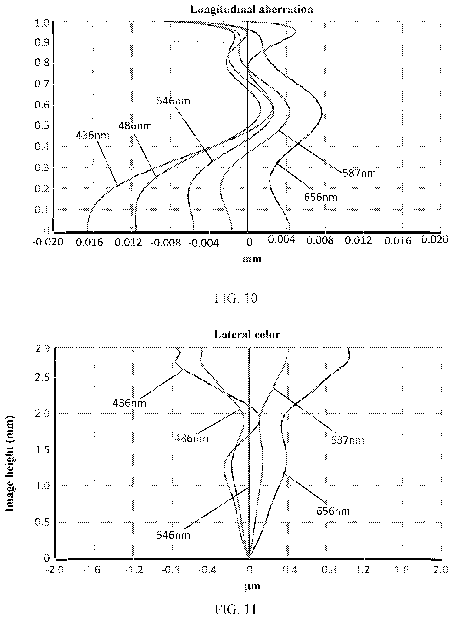
[0168] FIG. 10 and FIG. 11 illustrate a longitudinal aberration and a lateral color of light with wavelengths of 656 nm, 587 nm, 546 nm, 486 nm and 436 nm after passing the camera optical lens 30 according to the third embodiment, respectively. FIG. 12 illustrates a field curvature and a distortion of light with a wavelength of 546 nm after passing the camera optical lens 30 according to the third embodiment. In FIG. 12, a field curvature S is a field curvature in a sagittal direction, and T is a field curvature in a meridional direction.
[0169] Table 13 in the following lists values corresponding to the respective conditions in the embodiment according to the above conditions. Obviously, the camera optical lens 30 in the embodiment satisfies the above conditions.
[0170] In this embodiment, an entrance pupil diameter (ENPD) of the camera optical lens 30 is 2.036 mm, an image height (IH) of 1.0H is 2.900 mm, a field of view (FOV) in a diagonal direction is 72.00.degree.. Thus, the camera optical lens 30 meets the design requirements of large apertures, wide-angle and ultra-thin. Its on-axis and off-axis aberrations are fully corrected, thereby achieving excellent optical characteristics.
TABLE-US-00013 TABLE 13 Parameters and Fist Second Third conditions embodiment embodiment embodiment f1/f -4.96 -3.36 -2.02 d13/d14 9.79 5.12 2.51 f 3.886 3.877 3.869 f1 -19.283 -13.027 -7.821 f2 2.936 2.882 2.707 f3 -6.076 -6.260 -6.355 f4 7.440 7.261 6.802 f5 -241.820 -316.016 1713.939 f6 30.721 29.067 24.630 f7 -21.134 -20.421 -20.953 f8 9.404 9.008 8.132 f9 -4.076 -4.187 -4.416 f12 3.637 3.894 4.384 FNO 1.90 1.90 1.90 TTL 5.016 5.082 5.132 IH 2.900 2.900 2.900 FOV 72.00.degree. 72.10.degree. 72.00.degree.
[0171] It can be appreciated by one having ordinary skill in the art that the description above is only embodiments of the present disclosure. In practice, one having ordinary skill in the art can make various modifications to these embodiments in forms and details without departing from the scope of the present disclosure.
* * * * *
D00000
D00001
D00002
D00003
D00004
D00005
D00006
D00007
D00008
D00009
XML
uspto.report is an independent third-party trademark research tool that is not affiliated, endorsed, or sponsored by the United States Patent and Trademark Office (USPTO) or any other governmental organization. The information provided by uspto.report is based on publicly available data at the time of writing and is intended for informational purposes only.
While we strive to provide accurate and up-to-date information, we do not guarantee the accuracy, completeness, reliability, or suitability of the information displayed on this site. The use of this site is at your own risk. Any reliance you place on such information is therefore strictly at your own risk.
All official trademark data, including owner information, should be verified by visiting the official USPTO website at www.uspto.gov. This site is not intended to replace professional legal advice and should not be used as a substitute for consulting with a legal professional who is knowledgeable about trademark law.