Systems And Methods For Building, Operating And Controlling Multiple Regenerators And Transceivers Using Shared Common Components
Willner; Alan Eli ; et al.
U.S. patent application number 17/557424 was filed with the patent office on 2022-04-14 for systems and methods for building, operating and controlling multiple regenerators and transceivers using shared common components. The applicant listed for this patent is LyteLoop Technologies, LLC. Invention is credited to Dipayan Datta Choudhary, Daniel Damaghi, Ohad Harlev, Paul Francis McManamon, Armand Vedadi-Comte, Alan Eli Willner.
| Application Number | 20220113472 17/557424 |
| Document ID | / |
| Family ID | 1000006041970 |
| Filed Date | 2022-04-14 |
| United States Patent Application | 20220113472 |
| Kind Code | A1 |
| Willner; Alan Eli ; et al. | April 14, 2022 |
SYSTEMS AND METHODS FOR BUILDING, OPERATING AND CONTROLLING MULTIPLE REGENERATORS AND TRANSCEIVERS USING SHARED COMMON COMPONENTS
Abstract
A system comprising a recirculating loop configured to store an electromagnetic wave signal, the recirculating loop comprising a transmission medium and a plurality of transceivers configured to introduce the electromagnetic wave signal into the transmission medium and retrieve the electromagnetic wave signal from the transmission medium, and a signal conditioning system comprising a plurality of signal conditioners coupled to the transmission medium, the plurality of signal conditioners configured to amplify or regenerate the electromagnetic wave signal traveling in the transmission medium, one or more pump laser sources, wherein at least one of the one or more pump laser sources is configured to provide a pump laser beam to at least two of the plurality of signal conditioners, and one or more control circuits for controlling the plurality of signal conditioners, wherein at least one of the one or more control circuits is configured to control and monitor at least two of the plurality of signal conditioners, is disclosed.
| Inventors: | Willner; Alan Eli; (Los Angeles, CA) ; Damaghi; Daniel; (Great Neck, NY) ; Harlev; Ohad; (Closter, NJ) ; McManamon; Paul Francis; (Dayton, OH) ; Vedadi-Comte; Armand; (Port Washington, NY) ; Choudhary; Dipayan Datta; (Brooklyn, NY) | ||||||||||
| Applicant: |
|
||||||||||
|---|---|---|---|---|---|---|---|---|---|---|---|
| Family ID: | 1000006041970 | ||||||||||
| Appl. No.: | 17/557424 | ||||||||||
| Filed: | December 21, 2021 |
Related U.S. Patent Documents
| Application Number | Filing Date | Patent Number | ||
|---|---|---|---|---|
| 16672221 | Nov 1, 2019 | 11243355 | ||
| 17557424 | ||||
| 62755631 | Nov 5, 2018 | |||
| Current U.S. Class: | 1/1 |
| Current CPC Class: | G02B 6/2861 20130101; H01S 3/302 20130101; H01S 3/094026 20130101 |
| International Class: | G02B 6/28 20060101 G02B006/28; H01S 3/094 20060101 H01S003/094; H01S 3/30 20060101 H01S003/30 |
Claims
1. A system comprising: a recirculating loop configured to store an electromagnetic wave signal, the recirculating loop comprising a transmission medium; a plurality of signal conditioners coupled to the transmission medium, the plurality of signal conditioners configured to amplify or regenerate an electromagnetic wave signal traveling in the transmission medium; and one or more pump laser sources, wherein at least one of the one or more pump laser sources is configured to provide a pump laser beam to at least two of the plurality of signal conditioners.
2. The system of claim 1, wherein the transmission medium comprises at least one of a waveguide, an optical fiber, or free space.
3. The system of claim 1, wherein the plurality of signal conditioners comprise amplifiers, regenerators, or a combination of amplifiers and regenerators.
4. The system of claim 3, wherein: each of the amplifiers comprises a fiber amplifier doped with a gain medium; and the gain medium comprises at least one of a fluorescent element, a rare-earth element, or erbium.
5. The system of claim 1, further comprising a coupler configured to combine the pump laser beam with the electromagnetic wave signal and send the combined beam/signal to a corresponding one of the plurality of signal conditioners.
6. The system of claim 1, further comprising: one or more control circuits for controlling the plurality of signal conditioners, wherein at least one of the one or more control circuits is configured to control at least two of the plurality of signal conditioners; wherein the at least one of the one or more control circuits comprises: a photodetector configured to measure input and output optical powers of each of the at least two of the plurality of signal conditioners; and a processor configured to compare the measured input and output optical powers and adjust an input pump laser power for the each of the at least two of the plurality of signal conditioners.
7. The system of claim 6, further comprising a variable attenuator coupled to the at least one of the one or more pump laser sources and to the at least one of the one or more control circuits, wherein the variable attenuator is configured to control the pump laser beam to be sent to a corresponding one of the plurality of signal conditioners based on the adjusted input pump laser power determined by the processor in the at least one of the one or more control circuits.
8. The system of claim 3, wherein the regenerators are configured to re-amplify, re-shape, or re-time the electromagnetic wave signal traveling in the transmission medium.
9. The system of claim 8, further comprising one or more clock sources, wherein at least one of the one or more clock sources is configured to provide a clock signal to at least two of the regenerators for re-timing the electromagnetic wave signal.
10. The system of claim 3, wherein: the regenerators comprise crystals or optical fibers; and the crystals or the optical fibers are doped with at least one of a fluorescent element, a rare-earth element, or erbium.
11. The system of claim 3, wherein the regenerators comprise at least one of all-optical regenerators; at least one amplifier and at least one absorber; at least one amplifier configured to operate in a saturation regime; or at least one nonlinear filter.
12. A method for storing an electromagnetic wave signal in a transmission medium, the method comprising: amplifying or regenerating, using a plurality of signal conditioners coupled to the transmission medium, an electromagnetic signal traveling in the transmission medium; and providing, from one or more pump laser sources, pump laser beams to the plurality of signal conditioners, wherein at least one of the one or more pump laser sources provides a pump laser beam to at least two of the plurality of signal conditioners.
13. The method of claim 12, wherein the transmission medium comprises at least one of a waveguide, an optical fiber, or free space.
14. The method of claim 12, wherein the plurality of signal conditioners comprises amplifiers, regenerators, or a combination of amplifiers and regenerators.
15. The method of claim 14, wherein: each of the amplifiers comprises a fiber amplifier doped with a gain medium; and the gain medium comprises at least one of a fluorescent element, a rare-earth element, or erbium.
16. The method of claim 12, further comprising combining, using a coupler, the pump laser beam with the electromagnetic wave signal and sending, using the coupler, the combined beam/signal to a corresponding one of the plurality of signal conditioners.
17. The method of claim 12, further comprising: controlling, using one or more control circuits, the plurality of signal conditioners, wherein at least one of the one or more control circuits controls at least two of the plurality of signal conditioners; wherein: the at least one of the one or more control circuits comprises a photodetector and a processor; and the controlling step comprises: measuring, using the photodetector, input and output optical powers of each of the at least two of the plurality of signal conditioners; and comparing, using the processor, the measured input and output optical powers to adjust an input pump laser power for the each of the at least two of the plurality of signal conditioners.
18. The method of claim 17, further comprising controlling, using a variable attenuator coupled to the at least one of the one or more pump laser sources and to the at least one of the one or more control circuits, the pump laser beam to be sent to a corresponding one of the plurality of signal conditioners based on the adjusted input pump laser power determined by the comparing step.
19. The method of claim 14, wherein the regenerating step comprises re-amplifying, re-shaping, or re-timing, using the regenerators, the electromagnetic wave signal traveling in the transmission medium.
20. The method of claim 19, wherein the re-timing step comprises providing, using one or more clock sources, clock signals to the regenerators, wherein at least one of the one or more clock sources provides a clock signal to at least two of the regenerators.
21. The method of claim 12, wherein the regenerating step is performed all optically in an optical domain.
22. The system of claim 1, further comprising at least one of one or more multiplexers, wherein at least one of the one or more multiplexers is communicably coupled to at least two of the plurality of signal conditioners, or one or more demultiplexers, wherein at least one of the one or more demultiplexers is communicably coupled to at least two of the plurality of signal conditioners.
23. The method of claim 12, wherein the amplifying or regenerating step comprises at least one of using one or more multiplexers, wherein at least one of the one or more multiplexers is communicably coupled to at least two of the plurality of signal conditioners, or using one or more demultiplexers, wherein at least one of the one or more demultiplexers is communicably coupled to at least two of the plurality of signal conditioners.
Description
CROSS-REFERENCE TO RELATED APPLICATIONS
[0001] The present U.S. non-provisional patent application is a continuation application and claims the benefit of copending U.S. patent application Ser. No. 16/672,221, filed on Nov. 1, 2019, which claims the benefit of and priority to U.S. Provisional Patent Application No. 62/755,631, filed Nov. 5, 2018, the entire contents of each of which are incorporated herein by reference.
FIELD OF INVENTION
[0002] The present invention relates to systems and methods for building, operating and controlling multiple amplifiers, regenerators and/or transceivers using shared common components. The present invention also relates to using such systems and methods in conjunction with a recirculating loop for storing data in motion or other devices and systems.
BACKGROUND OF THE INVENTION
[0003] The expansion of data centers, broadband communications and computationally intensive signal processing is driving the demand for high capacity data storage that potentially consumes less power and has higher security. Modern data centers also often require rapid access to the same data stored on a common drive to perform, for example, high performance computing (HPC). In addition, there is an increasing interest among many actors within the information technology (IT) storage industry (e.g., end customers, data centers, in system programmers (ISP), in circuit programmers (ICP)) in being able to erase sensitive data (e.g., government data, military data) definitively and completely in an immediate manner.
[0004] Currently, solid state drives (SSDs), such as non-volatile NAND flash memory based drives, and hard disk drives (HDDs) are examples of storage devices used to store data in data centers. Conventional data centers based on those solid-state based storage devices have a variety of drawbacks. For example, data storage using those conventional storage devices consumes a large amount of power and requires expensive maintenance. In addition, data storage involving many of those conventional storage devices generates a large amount of heat, necessitating cooling systems, which in turn require additional cost and energy consumption. Moreover, the throughput at which data can be read from or written to those conventional storage devices is limited by the speed of electronics to, for example, a few Gbit/s. Additionally, when data is erased from a conventional non-volatile solid-state memory, an imprint of the erased data typically remains and one could recover the erased data with proper skills and technology. Furthermore, to scale storage in the data center using those conventional storage devices, it is necessary to either buy more of the storage devices or replace the current storage devices with better performing ones. Accordingly, constructing and upgrading data centers using the conventional storage devices is a costly and time-consuming process.
[0005] There is, therefore, a need for a data storage apparatus and method that overcomes one or more of the above and other deficiencies of data storage using conventional storage devices. In addition, there is a need for a more cost-effective and efficient design for building, operating and controlling multiple amplifiers, regenerators and/or transceivers that may be used in conjunction with data storage devices or systems, or in conjunction with other devices or systems.
SUMMARY OF THE INVENTION
[0006] It has now been found that the above and related objects of the present invention are obtained in the form of several related aspects, including systems and methods for building, operating and controlling multiple amplifiers, regenerators and/or transceivers using shared common components.
[0007] More particularly, the present invention relates to a system comprising a recirculating loop configured to store an electromagnetic wave (e.g., optical wave) signal, the recirculating loop comprising a transmission medium (e.g., free space, outer space, vacuum, underwater, crystals, nonlinear media, waveguides, optical fibers, to name a few) and a plurality of transceivers configured to introduce the electromagnetic wave signal into the transmission medium and retrieve the electromagnetic wave signal from the transmission medium, and a signal conditioning system comprising a plurality of signal conditioners coupled to the transmission medium, the plurality of signal conditioners configured to amplify or regenerate the electromagnetic wave signal traveling in the transmission medium, one or more pump laser sources, wherein at least one of the one or more pump laser sources is configured to provide a pump laser beam to at least two of the plurality of signal conditioners, and one or more control circuits for controlling the plurality of signal conditioners, wherein at least one of the one or more control circuits is configured to control at least two of the plurality of signal conditioners.
[0008] In at least one embodiment, the transmission medium comprises a waveguide.
[0009] In at least one embodiment, the waveguide comprises an optical fiber.
[0010] In at least one embodiment, the transmission medium comprises free space.
[0011] In at least one embodiment, the plurality of signal conditioners comprises amplifiers, regenerators, or a combination of amplifiers and regenerators.
[0012] In at least one embodiment, the amplifiers comprise at least one phase sensitive amplifier.
[0013] In at least one embodiment, the regenerators comprise at least one phase sensitive parametric amplifier.
[0014] In at least one embodiment, each of the amplifiers comprises a fiber amplifier doped with a gain medium.
[0015] In at least one embodiment, the gain medium comprises a fluorescent element.
[0016] In at least one embodiment, the gain medium comprises a rare-earth element.
[0017] In at least one embodiment, the gain medium comprises erbium.
[0018] In at least one embodiment, the system further comprises a coupler configured to combine the pump laser beam with the electromagnetic wave signal and send the combined beam/signal to a corresponding one of the plurality of signal conditioners.
[0019] In at least one embodiment, the at least one of the one or more control circuits comprises a photodetector configured to measure input and output optical powers of each of the at least two of the plurality of signal conditioners and a processor configured to compare the measured input and output optical powers and adjust an input pump laser power for the each of the at least two of the plurality of signal conditioners.
[0020] In at least one embodiment, the system further comprises a variable attenuator coupled to the at least one of the one or more pump laser sources and to the at least one of the one or more control circuits, wherein the variable attenuator is configured to control the pump laser beam to be sent to a corresponding one of the plurality of signal conditioners based on the adjusted input pump laser power determined by the processor in the at least one of the one or more control circuits.
[0021] In at least one embodiment, the regenerators are configured to re-amplify, re-shape, or re-time the electromagnetic wave signal traveling in the transmission medium.
[0022] In at least one embodiment, the system further comprises one or more clock sources, wherein at least one of the one or more clock sources is configured to provide a clock signal to at least two of the regenerators for re-timing the electromagnetic wave signal.
[0023] In at least one embodiment, the regenerators comprise crystals or optical fibers.
[0024] In at least one embodiment, the crystals or the optical fibers are doped with a fluorescent element.
[0025] In at least one embodiment, the crystals or the optical fibers are doped with a rare-earth element.
[0026] In at least one embodiment, the crystals or the optical fibers are doped with erbium.
[0027] In at least one embodiment, the regenerators comprise all-optical regenerators.
[0028] In at least one embodiment, the regenerators comprise at least one amplifier and at least one absorber.
[0029] In at least one embodiment, the regenerators comprise at least one amplifier configured to operate in a saturation regime.
[0030] In at least one embodiment, the regenerators comprise at least one nonlinear filter.
[0031] In at least one embodiment, the system further comprises one or more laser sources, wherein at least one of the one or more laser sources is configured to provide a laser beam to at least two of the plurality of transceivers.
[0032] In at least one embodiment, the system further comprises one or more laser sources, wherein each of the plurality of transceivers comprises one or more transmitters and one or more receivers, and at least one of the one or more laser sources is configured to provide a laser beam to at least one of the one or more transmitters in one of the plurality of transceivers and to at least one of the one or more receivers in the other one of the plurality of transceivers.
[0033] In at least one embodiment, the system further comprises one or more laser sources, wherein each of the plurality of transceivers comprises one or more transmitters and one or more receivers, and at least one of the one or more laser sources is configured to provide a laser beam to at least one of the one or more transmitters in one of the plurality of transceivers and to at least one of the one or more receivers in the same one of the plurality of transceivers.
[0034] In at least one embodiment, the system further comprises a single clock source configured to provide a clock signal to at least two of the plurality of transceivers.
[0035] In at least one embodiment, the at least one of the one or more laser sources provides the laser beam to a modulator in the at least one of the one or more transmitters in the one of the plurality of transceivers and to a mixer in the at least one of the one or more receivers in the other one of the plurality of transceivers.
[0036] In at least one embodiment, the at least one of the one or more laser sources provides the laser beam to a modulator in the at least one of the one or more transmitters in the one of the plurality of transceivers and to a mixer in the at least one of the one or more receivers in the same one of the plurality of transceivers.
[0037] In at least one embodiment, the single clock source provides the clock signal to an integrated circuit (IC) in each of the at least two of the plurality of transceivers.
[0038] In at least one embodiment, the plurality of transceivers is substantially co-located.
[0039] In at least one embodiment, the plurality of signal conditioners is substantially co-located.
[0040] In at least one embodiment, the system further comprises one or more multiplexers, wherein at least one of the one or more multiplexers is communicably coupled to at least two of the plurality of signal conditioners.
[0041] In at least one embodiment, the at least two of the plurality of signal conditioners comprise at least two regenerators.
[0042] In at least one embodiment, the at least two regenerators comprise at least two phase sensitive parametric amplifiers.
[0043] In at least one embodiment, the system further comprises one or more demultiplexers, wherein at least one of the one or more demultiplexers is communicably coupled to at least two of the plurality of signal conditioners.
[0044] In at least one embodiment, the at least two of the plurality of signal conditioners comprise at least two regenerators.
[0045] In at least one embodiment, the at least two regenerators comprise at least two phase sensitive parametric amplifiers.
[0046] The present invention further relates to a system comprising a transmission medium, a plurality of transceivers configured to introduce the electromagnetic wave signal into the transmission medium and retrieve the electromagnetic wave signal from the transmission medium, and one or more laser sources, wherein at least one of the one or more laser sources is configured to provide a laser beam to at least two of the plurality of transceivers.
[0047] In at least one embodiment, each of the plurality of transceivers comprises one or more transmitters and one or more receivers, and the at least one of the one or more laser sources provides the laser beam to at least one of the one or more transmitters in one of the at least two of the plurality of transceivers and to at least one of the one or more receivers in the other one of the at least two of the plurality of transceivers.
[0048] In at least one embodiment, each of the plurality of transceivers comprises one or more transmitters and one or more receivers, and at least one of the one or more laser sources is configured to provide a laser beam to at least one of the one or more transmitters in one of the plurality of transceivers and to at least one of the one or more receivers in the same one of the plurality of transceivers.
[0049] In at least one embodiment, the system further comprises a single clock source configured to provide a clock signal to at least two of the plurality of transceivers.
[0050] In at least one embodiment, the at least one of the one or more laser sources provides the laser beam to a modulator in the at least one of the one or more transmitters in the one of the at least two of the plurality of transceivers and to a mixer in the at least one of the one or more receivers in the other one of the at least two of the plurality of transceivers.
[0051] In at least one embodiment, the at least one of the one or more laser sources provides the laser beam to a modulator in the at least one of the one or more transmitters in the one of the plurality of transceivers and to a mixer in the at least one of the one or more receivers in the same one of the plurality of transceivers.
[0052] In at least one embodiment, the single clock source provides the clock signal to an IC in each of the at least two of the plurality of transceivers.
[0053] In at least one embodiment, the transmission medium comprises a waveguide.
[0054] In at least one embodiment, the waveguide comprises an optical fiber.
[0055] In at least one embodiment, the transmission medium comprises free space.
[0056] In at least one embodiment, the transmission medium is configured to store an electromagnetic wave signal.
[0057] In at least one embodiment, the plurality of transceivers is substantially co-located.
[0058] In addition, the present invention also relates to a method for storing an electromagnetic wave signal in a transmission medium, the method comprising amplifying or regenerating, using a plurality of signal conditioners coupled to the transmission medium, an electromagnetic signal traveling in the transmission medium, providing, from one or more pump laser sources, pump laser beams to the plurality of signal conditioners, wherein at least one of the one or more pump laser sources provides a pump laser beam to at least two of the plurality of signal conditioners, and controlling, using one or more control circuits, the plurality of signal conditioners, wherein at least one of the one or more control circuits controls at least two of the plurality of signal conditioners.
[0059] In at least one embodiment, the transmission medium comprises a waveguide.
[0060] In at least one embodiment, the waveguide comprises an optical fiber.
[0061] In at least one embodiment, the transmission medium comprises free space.
[0062] In at least one embodiment, the plurality of signal conditioners comprises amplifiers, regenerators, or a combination of amplifiers and regenerators.
[0063] In at least one embodiment, the amplifiers comprise at least one phase sensitive amplifier.
[0064] In at least one embodiment, the regenerators comprise at least one phase sensitive parametric amplifier.
[0065] In at least one embodiment, each of the amplifiers comprises a fiber amplifier doped with a gain medium.
[0066] In at least one embodiment, the gain medium comprises a fluorescent element.
[0067] In at least one embodiment, the gain medium comprises a rare-earth element.
[0068] In at least one embodiment, the gain medium comprises erbium.
[0069] In at least one embodiment, the method further comprises combining, using a coupler, the pump laser beam with the electromagnetic wave signal and sending, using the coupler, the combined beam/signal to a corresponding one of the plurality of signal conditioners.
[0070] In at least one embodiment, the at least one of the one or more control circuits comprises a photodetector and a processor, and the controlling step comprises measuring, using the photodetector, input and output optical powers of each of the at least two of the plurality of signal conditioners, and comparing, using the processor, the measured input and output optical powers to adjust an input pump laser power for the each of the at least two of the plurality of signal conditioners.
[0071] In at least one embodiment, the method further comprises controlling, using a variable attenuator coupled to the at least one of the one or more pump laser sources and to the at least one of the one or more control circuits, the pump laser beam to be sent to a corresponding one of the plurality of signal conditioners based on the adjusted input pump laser power determined by the comparing step.
[0072] In at least one embodiment, the regenerating step comprises re-amplifying, re-shaping, or re-timing, using the regenerators, the electromagnetic wave signal traveling in the transmission medium.
[0073] In at least one embodiment, the re-timing step comprises providing, using one or more clock sources, clock signals to the regenerators, wherein at least one of the one or more clock sources provides a clock signal to at least two of the regenerators.
[0074] In at least one embodiment, the regenerating step is performed all optically in an optical domain.
[0075] In at least one embodiment, the plurality of signal conditioners is substantially co-located.
[0076] In at least one embodiment, the amplifying or regenerating step comprises using one or more multiplexers, wherein at least one of the one or more multiplexers is communicably coupled to at least two of the plurality of signal conditioners.
[0077] In at least one embodiment, the at least two of the plurality of signal conditioners comprise at least two regenerators.
[0078] In at least one embodiment, the at least two regenerators comprise at least two phase sensitive parametric amplifiers.
[0079] In at least one embodiment, the amplifying or regenerating step comprises using one or more demultiplexers, wherein at least one of the one or more demultiplexers is communicably coupled to at least two of the plurality of signal conditioners.
[0080] In at least one embodiment, the at least two of the plurality of signal conditioners comprise at least two regenerators.
[0081] In at least one embodiment, the at least two regenerators comprise at least two phase sensitive parametric amplifiers.
[0082] Furthermore, the present invention also relates to a method of using a plurality of transceivers connected to a transmission medium, the method comprising inputting, using the plurality of transceivers, an electromagnetic wave signal into the transmission medium, outputting, using the plurality of transceivers, the electromagnetic wave signal from the transmission medium, and providing, from a single laser source, a laser beam to at least two of the plurality of transceivers.
[0083] In at least one embodiment, each of the plurality of transceivers comprises one or more transmitters and one or more receivers, and the single laser source provides the laser beam to at least one of the one or more transmitters in one of the at least two of the plurality of transceivers and to at least one of the one or more receivers in the other one of the at least two of the plurality of transceivers.
[0084] In at least one embodiment, each of the plurality of transceivers comprises one or more transmitters and one or more receivers, the method further comprising the step of providing, from the single laser source, a laser beam to at least one of the one or more transmitters in one of the plurality of transceivers and to at least one of the one or more receivers in the same one of the plurality of transceivers.
[0085] In at least one embodiment, the method further comprises providing, from a single clock source, a clock signal to at least two of the one or more transceivers.
[0086] In at least one embodiment, the single laser source provides the laser beam to a modulator in the at least one of the one or more transmitters in the one of the at least two of the plurality of transceivers and to a mixer in the at least one of the one or more receivers in the other one of the at least two of the plurality of transceivers.
[0087] In at least one embodiment, the single laser source provides the laser beam to a modulator in the at least one of the one or more transmitters in the one of the plurality of transceivers and to a mixer in the at least one of the one or more receivers in the same one of the plurality of transceivers.
[0088] In at least one embodiment, the single clock source provides the clock signal to an IC in each of the at least two of the plurality of transceivers.
[0089] In at least one embodiment, the transmission medium comprises a waveguide.
[0090] In at least one embodiment, the waveguide comprises an optical fiber.
[0091] In at least one embodiment, the transmission medium comprises free space.
[0092] In at least one embodiment, the transmission medium is configured to store an electromagnetic wave signal.
[0093] In at least one embodiment, the plurality of transceivers is substantially co-located.
[0094] Although specific features, capabilities and advantages have been enumerated above, various embodiments may include some, none, or all of the enumerated features, capabilities and advantages. These and other technical features, capabilities and advantages of the disclosed subject matter, along with the invention itself, will be more fully understood after a review of the following figures, detailed descriptions and claims.
BRIEF DESCRIPTION OF THE DRAWINGS
[0095] Exemplary embodiments of the present invention will be described with references to the accompanying figures, wherein:
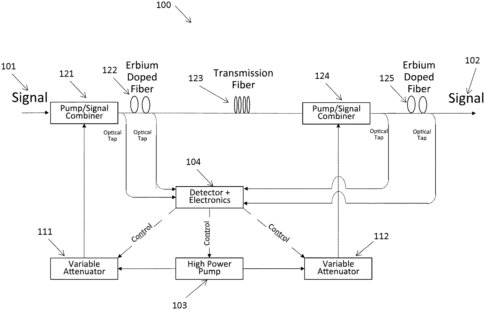
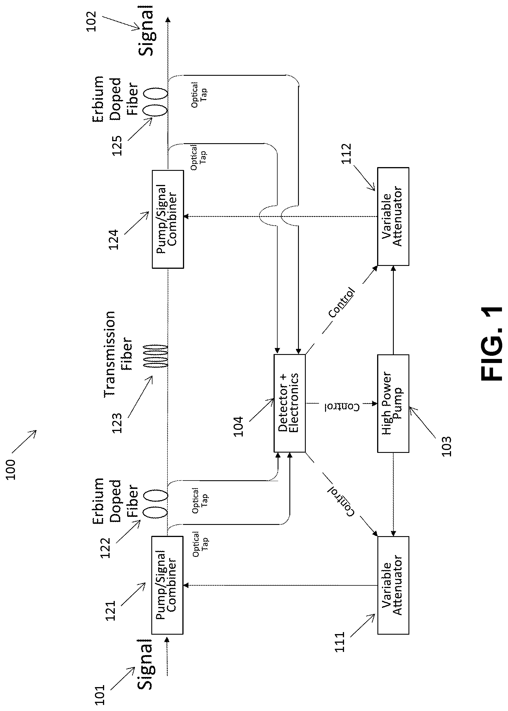
[0096] FIG. 1 is a schematic diagram of multiple amplifiers sharing components in accordance with an exemplary embodiment of the present invention.
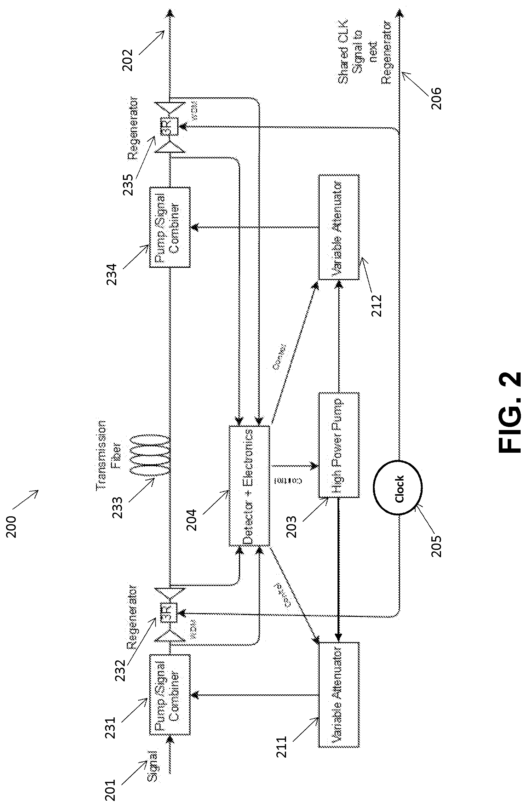
[0097] FIG. 2 is a schematic diagram of multiple regenerators sharing components n accordance with an exemplary embodiment of the present invention.
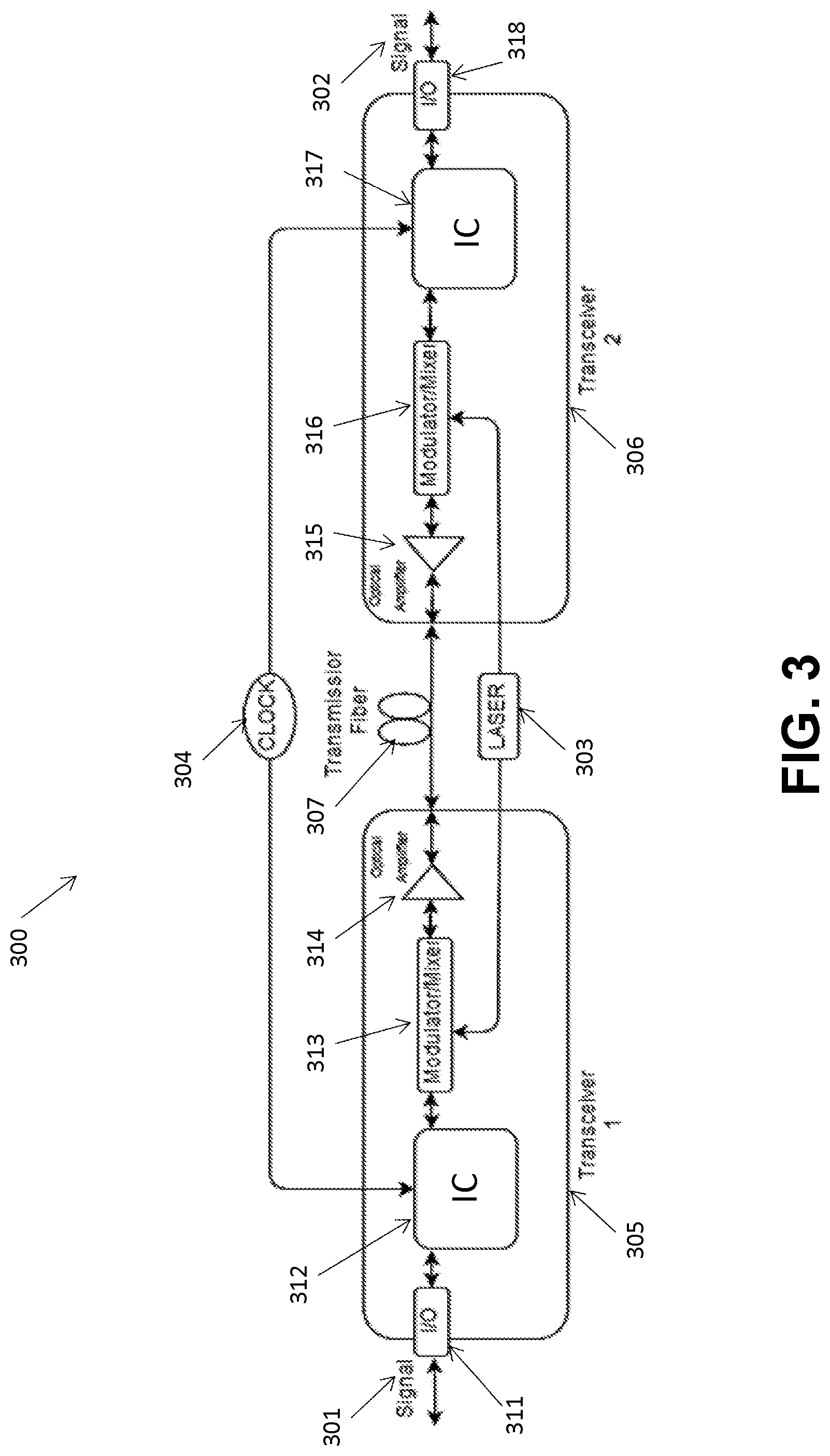
[0098] FIG. 3 is a schematic diagram of multiple transceivers sharing components in accordance with an exemplary embodiment of the present invention.
DETAILED DESCRIPTION OF PREFERRED EMBODIMENTS
[0099] Information or any kind of data can be stored as electromagnetic waves (e.g., coherent (i.e., laser) or non-coherent optical beams, radio frequency (RF) signals, and other types of electromagnetic wave signals, to name a few), which can be transmitted and/or reflected between structures or within structures in various transmission media (e.g., free space, outer space, vacuum, underwater, crystals, nonlinear media, waveguides, optical fibers, to name a few). For example, a recirculating loop may be used to store "data in motion" by keeping electromagnetic wave signals, which may carry data, in a continuous motion, transmitted and/or reflected between or within structures and regenerated (e.g., by signal amplification) as needed. The recirculating loop may comprise a transmission medium (e.g., free space, waveguide, optical fiber, cavity under a vacuum condition, to name a few) through which an electromagnetic wave signal can travel, and one or more transceivers configured to introduce the electromagnetic wave signal into the transmission medium and retrieve the electromagnetic wave signal from the transmission medium. For example, the recirculating loop may be formed by satellites and/or other vessels that reflect or otherwise retransmit the data in free space. In another example, the recirculating loop may comprise a waveguide, such as an optical fiber. Various systems and methods of storing data in motion in a recirculating loop are described in U.S. patent application Ser. No. 15/465,356, which has been published as US 2017/0280211 A1 and is incorporated by reference herein in its entirety.
[0100] In one example, a satellite-based laser, a land or on/under-water based laser or optical beam, or any other electromagnetic radiation may be used to transmit and store data. The terms "electromagnetic wave signal" and "electromagnetic wave beam" are used herein interchangeably. Electromagnetic radiation or electromagnetic beam as used herein may include any kind of electromagnetic signal, including a laser beam or signal, a maser beam or signal, an optical beam or signal, or any type of wired or wireless signal, including acoustic waves, radio waves, IR radiation, UV radiation, microwave-band transmission, or any combination of more than one of the foregoing. While referred to herein sometimes simply as a laser beam or signal, other types of optical signals and other types of electromagnetic radiation transmissions, including radio waves, microwaves, IR, UV and combinations of bandwidths of wavelengths of electromagnetic radiation, whether guided, shaped, phased, or none of the foregoing, are also intended to be included.
[0101] In embodiments, systems for storing electromagnetic wave signals in a recirculating loop may be configured to extinguish or "turn off" the electromagnetic wave signals stored therein. When the electromagnetic wave signals are extinguished, data stored therein is definitively and instantly lost and cannot be recovered, unlike the data erased from a solid-state memory.
[0102] Disclosed are systems and methods for building, operating and/or controlling multiple signal conditioners (e.g., amplifiers, regenerators, a combination of amplifiers and regenerators, to name a few) and/or transceivers using shared common components to achieve a more efficient and/or cost-effective design. Such systems and methods may be used in conjunction with a recirculating loop for storing data in motion, or with other devices or systems of the similar architecture.
[0103] For example, multiple signal conditioners, such as amplifiers, regenerators, or a combination of amplifiers and regenerators, may be placed along the path of an electromagnetic wave signal to restore the passing electromagnetic wave signal to its original or previous state and/or to compensate for any degradation.
[0104] An amplifier may be any device configured to amplify an electromagnetic wave signal. In embodiments, an amplifier may comprise crystals or optical fibers. In embodiments, the crystals and optical fibers may be doped with a gain medium comprising, for example, a fluorescent element or a rare-earth element, such as erbium. In embodiments, the optical fiber used in the amplifier may include additional devices at the input to inject the electromagnetic wave signal into the optical fiber, and other devices at the output to restore the electromagnetic wave beam to its original shape and size.
[0105] Each amplifier may require many, various components. For example, an amplifier may be used in conjunction with a pump laser source, which is configured to provide a pump laser beam to the amplifier. In another example, an amplifier may be used in conjunction with a control circuit, which is configured to control the operation of the amplifier.
[0106] Amplifiers, such as erbium-doped fiber amplifiers (EDFAs), are typically used to periodically amplify electromagnetic wave signals in an optical fiber communication link that extends over a long distance. Such periodic gains provided by the amplifiers along the fiber communication link offset the signal power loss due to the transmission optical fiber. In a conventional system, amplifiers are placed apart from each other (e.g., placed at intervals of 50 to 100 kilometers) such that each amplifier is likely isolated from the other amplifiers and cannot readily "share" components with the other amplifiers. Each amplifier comprises many components. For example, each EDFA used in such a conventional system may comprise erbium doped fiber, pump laser source, optical isolator, optical coupler and control circuit.
[0107] By contrast, a system, such as a system for storing data in motion using a recirculating loop, can be configured such that multiple amplifiers can be placed at the same location, or substantially co-located, i.e., located in the vicinity of each other (e.g., near or substantially adjacent to each other, physically located in the same room or space, etc.). In such a system, it is possible for multiple amplifiers such as EDFAs to share one or more common components in order to achieve a more efficient and cost-effective design.
[0108] In addition, systems and methods for building, operating and/or controlling multiple signal conditioners (e.g., amplifiers, regenerators, a combination of amplifiers and regenerators, to name a few) and/or transceivers using shared common components may also be used in conjunction with other types of architectures wherein transmission equipment are placed at the same location, or substantially co-located, i.e., located in the vicinity of each other (e.g., near or substantially adjacent to each other, physically located in the same room or space, etc.). Examples of these types of architectures may include, but are not limited to, data centers where information may be sent and received within the same facility, and sensing equipment, such as RADAR and LIDAR, which send and receive data to and from the same location.
[0109] FIG. 1 is a schematic diagram of a system 100 comprising at least two substantially co-located EDFAs sharing common components, such as a pump laser source 103 and/or a control circuit 104, in accordance with an exemplary embodiment of the present invention. In embodiments, the substantially co-located EDFAs may be coupled to each other by a transmission medium, such as a transmission fiber 123. FIG. 1 shows an electromagnetic wave signal 101 entering a first EDFA 121, 122. The amplified signal then passes through a transmission fiber 123. The signal then enters a second EDFA 124, 125 and exits the second EDFA as an amplified signal 102.
[0110] A single pump laser source 103 having sufficient output power may be used to provide a pump laser beam to two or more multiple EDFAs. As shown in FIG. 1, the output power of the pump laser source 103 may be split and sent to variable attenuators 111, 112, each of which may be coupled to the corresponding one of the multiple EDFAs. The variable attenuator 111, 112 may be configured to control the specific pump laser power needed for the corresponding EDFA. The pump laser beam may then be sent from the variable attenuators 111, 112 to erbium-doped fibers 122, 125 through the corresponding couplers 121, 124. Each of the couplers 121, 124 may be configured to combine the pump laser beam from the pump laser source 103 (via variable attenuators 111, 112) with the electromagnetic wave signal and send the combined pump laser beam and electromagnetic wave signal to the corresponding erbium-doped fiber 122, 125 to achieve amplification of the electromagnetic wave signal.
[0111] As shown in FIG. 1, at least two of the multiple EDFAs may be used in conjunction with a shared control circuit 104, which may be configured to control the operation of the EDFAs, such as the gain of the amplifiers. For example, the input power to and output power from the erbium-doped fiber 122, 125 may be measured by using, for example, a photodetector in the control circuit 104. The measured input and output powers may then be compared by using, for example, a processor comprising electronic circuitry in the control circuit 104 to determine the amplifier characteristics, such as gain. As a result of the comparison, the pump laser power input to the coupler 121, 124 can be adjusted accordingly. In embodiments, this adjustment of the pump laser power input may be performed by the pump laser source 103 and/or variable attenuator 111, 112 based on control signals from the control circuit 104, as shown in FIG. 1.
[0112] In embodiments, the shared control circuit 104 may be much faster than the changes that might occur to the amplifier gain. As such, by using many couplers and taking optical/electronic measurements sequentially from different multiple erbium-doped fibers, many EDFAs can share a single control circuit.
[0113] In embodiments, the pump laser source 103 and the control circuit 104 may account for a large fraction of the cost of the multiple EDFAs in the system 100. As such, sharing of the pump laser source and/or the control circuit by multiple EDFAs can provide the benefit of efficiency and cost-effectiveness.
[0114] As another example, phase sensitive amplifiers (PSAs) may be configured such that substantially co-located multiple PSAs can share one or more common components, such as a pump laser source, control circuit, and/or clock signal.
[0115] In long distance communication systems, wave distortion and relative time delay deviation may be accumulated even when amplifiers for regenerating signal amplitudes are used. This problem may require periodic regeneration by one or more regenerators to regenerate the original/previous waveform and synchronization of signals. For example, regenerators may be used for communication systems involving a distance of greater than 100 kilometers. A full signal regeneration, which is typically called a "3R" process, involves signal retiming, reshaping, and reamplification (or amplification) of the electromagnetic wave signal. A regenerator may be configured to conduct full electromagnetic wave signal regeneration. Alternatively, a regenerator may be configured to restore only some aspects of the electromagnetic wave signal by re-timing and/or re-shaping and/or re-amplification of the electromagnetic wave signal in part. In embodiments, the regenerator may also be configured to implement error correction to restore lost information or correct errors introduced into the data in motion. In embodiments, the regenerator may be used in conjunction with Wavelength Division Multiplexing (WDM), which enables the regenerator to improve the signal quality on different wavelength channels.
[0116] Any apparatus configured to re-amplify, re-shape, and/or re-time the electromagnetic wave signal in full or in part may be used to build regenerators. Regenerators can be implemented in various ways. In embodiments, the regenerator may be an all-optical or optoelectronic regenerator, wherein the all-optical regenerator is configured to regenerate the electromagnetic wave signal all optically in the optical domain, while the optoelectronic regenerator is configured to convert the electromagnetic wave signal to a corresponding electrical signal in the electrical domain, regenerate the converted electrical signal electrically and convert the regenerated electrical signal to a corresponding electromagnetic wave signal in the optical domain. In embodiments, the regenerator may comprise at least one amplifier and at least one absorber. In embodiments, the regenerator may comprise at least one amplifier configured to operate in a saturation regime. In embodiments, the regenerator may comprise a nonlinear filter configured to provide gain stabilization and/or reduce noise in the electromagnetic wave signal. In embodiments, the regenerator may comprise crystals or optical fibers. In embodiments, the regenerator may comprise crystals or optical fibers doped by a fluorescent element or a rare-earth element, such as erbium. In embodiments, the optical fiber used in the regenerator may comprise additional devices at the input to inject the electromagnetic wave signal into the optical fiber, and other devices at the output to restore the electromagnetic wave beam to its original shape and size. In embodiments, the regenerator may comprise at least one phase sensitive parametric amplifier.
[0117] In a system (e.g., a system for storing data in motion using a recirculating loop) where multiple regenerators can be substantially co-located, it is possible for multiple regenerators to share one or more common components in order to achieve a more efficient and cost-effective design.
[0118] FIG. 2 is a schematic diagram of a system 200 comprising at least two substantially co-located regenerators 232, 235 sharing common components, such as a pump laser source 203, a control circuit 204, and/or a clock source 205, in accordance with an exemplary embodiment of the present invention. In embodiments, the substantially co-located regenerators 232, 235 may be coupled to each other by a transmission medium, such as a transmission fiber 233. FIG. 2 shows an electromagnetic wave signal 201 entering a first regenerator 232 through the corresponding coupler 231. The regenerated signal then passes through a transmission fiber 233. The signal then enters a second regenerator 235 through the corresponding coupler 234 and exits the second regenerator as a regenerated signal 202.
[0119] A single pump laser source 203 having sufficient output power may be used to provide a pump laser beam to two or more multiple regenerators 232, 235. As shown in FIG. 2, the output power of the pump laser source 203 may be split and sent to variable attenuators 211, 212, each of which may be coupled to the corresponding one of the multiple regenerators 232, 235. The variable attenuator 211, 212 may be configured to control the specific pump laser power needed for the corresponding regenerator. The pump laser beam may then be sent from the variable attenuators 211, 212 to the regenerators 232, 235 through the corresponding couplers 231, 234. Each of the couplers 231, 234 may be configured to combine the pump laser beam from the pump laser source 203 (via variable attenuators 211, 212) with the electromagnetic wave signal and to send the combined pump laser beam and electromagnetic wave signal to the corresponding regenerator 232, 235 to achieve full or partial regeneration of the electromagnetic wave signal.
[0120] As shown in FIG. 2, at least two of the multiple regenerators 232, 235 may be used in conjunction with a shared control circuit 204, which may be configured to control the operation of the regenerators, such as the gain of the regenerators. For example, the input power to and output power from the regenerator 232, 235 may be measured by using, for example, a photodetector in the control circuit 204. The measured input and output powers may then be compared by using, for example, a processor comprising electronic circuitry in the control circuit 204 to determine the regenerator characteristics, such as gain. As a result of the comparison, the pump laser power input to the coupler 231, 234 can be adjusted accordingly. In embodiments, this adjustment of the pump laser power input may be performed by the pump laser source 203 and/or variable attenuator 211, 212 based on control signals from the control circuit 204, as shown in FIG. 2.
[0121] In embodiments, the shared control circuit 204 may be much faster than the changes that might occur to the regenerator gain. As such, by using many couplers and taking optical/electronic measurements sequentially from different multiple regenerators, many regenerators can share a single control circuit.
[0122] As shown in FIG. 2, at least two of the substantially co-located multiple regenerators 232, 235 may use a shared clock source 205, which may be configured to provide a clock signal to each of at least two of the multiple regenerators 232, 235 for re-timing the electromagnetic wave signal.
[0123] In embodiments, the system 200 may further comprise one or more multiplexers (not shown in FIG. 2), wherein at least one of the one or more multiplexers is communicably coupled to and shared by the two substantially co-located regenerators 232, 235. Additionally or alternatively, the system 200 may further comprise one or more demultiplexers (not shown in FIG. 2), wherein at least one of the one or more demultiplexers is communicably coupled to and shared by the two substantially co-located regenerators 232, 235. In embodiments, the two regenerators 232, 235 sharing at least one of the one or more multiplexers and/or at least one of the one or more demultiplexers comprise phase sensitive parametric amplifiers.
[0124] In embodiments, the pump laser source 203, the control circuit 204, the clock source 205 and/or multiplexers/demultiplexers may account for a large fraction of the cost of the multiple regenerators in the system 200. As such, sharing of one or more common components, such as pump laser source, control circuit, clock source and/or multiplexers/demultiplexers, by multiple regenerators can provide the benefit of efficiency, cost-effectiveness and overall reduction in power consumption of the regenerators.
[0125] Transceivers may be used to transmit and receive electromagnetic wave signals through a transmission medium, such as free space, waveguide, optical fiber, to name a few. In embodiments, a transceiver may comprise one or more transmitters and one or more receivers. In embodiments, a transceiver may comprise many components, such as input/output interfaces, modulators, mixers, amplifiers, active optic cables, and/or integrated circuits (e.g., application specific integrated circuit (ASIC)) comprising, for example, a digital signal processor (DSP), an optical transport network (OTN) framer/deframer, an analog-to-digital converter (ADC), and/or a digital-to-analog converter. (DAC).
[0126] In a system (e.g., a system for storing data in motion using a recirculating loop) where multiple transceivers can be substantially co-located, it is possible for multiple transceivers to share one or more common components in order to achieve a more efficient and cost-effective design.
[0127] FIG. 3 is a schematic diagram of a system 300 comprising at least two substantially co-located transceivers 305, 306 sharing common components, such as a laser source 303 and/or a clock source 304, in accordance with an exemplary embodiment of the present invention. In embodiments, the substantially co-located transceivers 305, 306 may be coupled to each other by a transmission medium, such as a transmission fiber 307, as shown in FIG. 3. FIG. 3 shows an electromagnetic wave signal 301 traveling in to or out of a first transceiver 305 through a first input/output interface 311, and the corresponding electromagnetic wave signal 302 traveling in to or out of a second transceiver 306 through a second input/output interface 318. For example, the electromagnetic wave signal 301 enters the first transceiver 305 through the first input/output interface 311 and then passes through a first integrated circuit (IC) 312, a first modulator/mixer 313 and a first amplifier 314 of the first transceiver 305. The signal is then transmitted through the transmission fiber 307, and then passes through a second amplifier 315, a second modulator/mixer 316 and a second integrated circuit 317 of the second transceiver 306. The second transceiver 306 outputs the corresponding electromagnetic wave signal 302 through the second input/output interface 318. In alternative embodiments, the electromagnetic wave signal 302 may travel in the reverse direction such that the first transceiver 305 outputs the corresponding electromagnetic wave signal 301 through the first input/output interface 311.
[0128] At least two of the substantially co-located multiple transceivers 305, 306 may use a shared laser source 303. As shown in FIG. 3, the laser source 303 may be configured to provide a laser beam to the first transceiver 305 and to the second transceiver 306. In embodiments, if the first transceiver 305 is a transmit side and the second transceiver 306 is a receive side and each transceiver comprises one or more transmitters and one or more receivers, the laser source 303 may provide a laser beam to at least one of the one or more transmitters in the first transceiver 305 and to at least one of one or more receivers in the second transceiver 306. In embodiments, if the first transceiver 305 is a transmit side and the second transceiver 306 is a receive side and each transceiver comprises one or more transmitters and one or more receivers, the laser source 303 may provide a laser beam to a modulator 313 in at least one of the one or more transmitters in the first transceiver 305 and to a mixer 316 in at least one of one or more receivers in the second transceiver 306, as shown in FIG. 3. It should be noted that the pairs of transceivers that are sharing the laser sources will often transmit and receive light on the same wavelength.
[0129] In further embodiments, the laser source 303 may be configured to provide a laser beam to at least one of the one or more transmitters in at least one of the multiple transceivers 305, 306 and to at least one of the one or more receivers in the same one of the multiple transceivers 305, 306. In further embodiments, the laser source 303 may be configured to provide a laser beam to a modulator in at least one of the one or more transmitters in at least one of the multiple transceivers 305, 306 and to a mixer in at least one of the one or more receivers in the same one of the multiple transceivers 305, 306.
[0130] At least two of the substantially co-located multiple transceivers may use a shared clock source, which may be configured to provide a clock signal to each of at least two of the multiple transceivers. In embodiments, as shown in FIG. 3, a clock source 304 may be configured to provide a clock signal to the first IC 312 in the first transceiver 305 and to the second IC 317 in the second transceiver 306.
[0131] The use of shared components, such as laser sources and/or clock sources, by multiple transceivers leads to an efficient and cost-effective design by, for example, reducing the number of components used, decreasing the amount of digital signal processing used, reducing power consumption and lowering the capital and operating cost of manufacturing and maintaining the transceivers without affecting the performance of transmission.
[0132] While this invention has been described in conjunction with exemplary embodiments outlined above and illustrated in the drawings, it is evident that the principles of the present invention may be implemented using any number of techniques, whether currently known or not, and many alternatives, modifications and variations in form and detail will be apparent to those skilled in the art. Modifications, additions, or omissions may be made to the systems, apparatuses, and methods described herein without departing from the scope of the present invention. For example, the components of the systems and apparatuses may be integrated or separated. Furthermore, the operations of the systems and apparatuses disclosed herein may be performed by more, fewer, or other components and the methods described may include more, fewer, or other steps. Additionally, steps may be performed in any suitable order.
[0133] As defined herein, electromagnetic waves include acoustic waves. Accordingly, storage in motion of information or any kind of data can also be implemented using acoustic (i.e., sound) waves. Representative values for the speed of sound include about 1,500 m/sec in water, about 330 m/sec in air, and about 6,000 m/sec in steel. (There are a range of velocities for each case.) In terms of frequency, sound waves can be in the region of tens of MHz. For example, some medical ultrasound devices operate in the regions of tens of MHz. Usually, lower frequency sound also has less attenuation over distance.
[0134] A benefit of using acoustic waves for storage in motion is the relatively slower speed of sound. In this regard, if the wave signal carrying information or any kind of data in motion is an acoustic wave, the much lower speed of sound (as compared to the speed of light) enables one to store a greater amount of data in motion in a cavity without requiring a higher data rate at which the data is introduced into the cavity.
[0135] Acoustic waves require some medium in order to propagate. Information or any kind of data can be transmitted and/or reflected between structures or within structures using acoustic waves in various transmission media (e.g., air and steel, to name a few). Embodiments of storage in motion using acoustic waves could be constructed using such media. For steel, railroad tracks could be a long-distance medium. Acoustic waves can be generated using various sources of vibration, including crystal transducers and speakers, to name a few. Microphones detect acoustic waves. There is a significant base of acoustic technology in sound systems, in systems to eliminate vibration, and in systems to measure vibration. This device technology can be utilized in developing storage in motion systems using acoustic waves in accordance with the principles employed in the embodiments disclosed in the present application.
[0136] Accordingly, the exemplary embodiments of the invention, as set forth above, are intended to be illustrative, not limiting, and the spirit and scope of the present invention is to be construed broadly and limited only by the appended claims, and not by the foregoing specification.
[0137] In addition, unless otherwise specifically noted, articles depicted in the drawings are not necessarily drawn to scale.
* * * * *
D00000
D00001
D00002
D00003
XML
uspto.report is an independent third-party trademark research tool that is not affiliated, endorsed, or sponsored by the United States Patent and Trademark Office (USPTO) or any other governmental organization. The information provided by uspto.report is based on publicly available data at the time of writing and is intended for informational purposes only.
While we strive to provide accurate and up-to-date information, we do not guarantee the accuracy, completeness, reliability, or suitability of the information displayed on this site. The use of this site is at your own risk. Any reliance you place on such information is therefore strictly at your own risk.
All official trademark data, including owner information, should be verified by visiting the official USPTO website at www.uspto.gov. This site is not intended to replace professional legal advice and should not be used as a substitute for consulting with a legal professional who is knowledgeable about trademark law.