Line Feed-through For Feeding A Line Through A Building Component
SIMON; Sebastian ; et al.
U.S. patent application number 17/533344 was filed with the patent office on 2022-04-14 for line feed-through for feeding a line through a building component. This patent application is currently assigned to Hilti Aktiengesellschaft. The applicant listed for this patent is Hilti Aktiengesellschaft. Invention is credited to Sebastian SIMON, Frank Thiemann.
| Application Number | 20220112971 17/533344 |
| Document ID | / |
| Family ID | 1000006048615 |
| Filed Date | 2022-04-14 |
| United States Patent Application | 20220112971 |
| Kind Code | A1 |
| SIMON; Sebastian ; et al. | April 14, 2022 |
LINE FEED-THROUGH FOR FEEDING A LINE THROUGH A BUILDING COMPONENT
Abstract
The invention relates to a line feed-through (1) for feeding a line (4) through a building component, comprising one or more sealing arrangements (2) for feeding the line (4) through, wherein the one or more sealing arrangements (2) have at least two sealing structures (51) lying opposite each other, wherein at least one first of the sealing structures (51) has an arrangement of elongate fins (53) adjacent to each other, the protruding ends of which lie against a second of the sealing structures (51) and thus seal the passage region.
| Inventors: | SIMON; Sebastian; (Buchloe Lindenberg, DE) ; Thiemann; Frank; (Landsberg/Lech, DE) | ||||||||||
| Applicant: |
|
||||||||||
|---|---|---|---|---|---|---|---|---|---|---|---|
| Assignee: | Hilti Aktiengesellschaft Schaan LI |
||||||||||
| Family ID: | 1000006048615 | ||||||||||
| Appl. No.: | 17/533344 | ||||||||||
| Filed: | November 23, 2021 |
Related U.S. Patent Documents
| Application Number | Filing Date | Patent Number | ||
|---|---|---|---|---|
| 16339012 | Apr 3, 2019 | |||
| PCT/EP2017/073715 | Sep 20, 2017 | |||
| 17533344 | ||||
| Current U.S. Class: | 1/1 |
| Current CPC Class: | F16L 5/025 20130101; H02G 3/0412 20130101; F16L 5/04 20130101; H02G 3/22 20130101 |
| International Class: | F16L 5/02 20060101 F16L005/02; F16L 5/04 20060101 F16L005/04; H02G 3/04 20060101 H02G003/04; H02G 3/22 20060101 H02G003/22 |
Foreign Application Data
| Date | Code | Application Number |
|---|---|---|
| Oct 5, 2016 | EP | 16192338.8 |
Claims
1-11. (canceled)
12. A line penetration, comprising: a housing comprising a passage; a first seal adjacent to a first opening of the passage; and a retainer within the housing at a location between the first opening of the passage and a second opening of the passage, wherein the first seal includes elongated extensions that at least partially enclose the first opening of the passage, the elongated extensions moving to allow a line to pass through the first opening and the passage in an installed state, and wherein the retainer configured to apply a force against the line in the installed state.
13. The line penetration of claim 12, wherein the elongated extensions are made of a flexible material.
14. The line penetration of claim 12, wherein the elongated extensions are oriented in a direction crossing an axial direction of the passage.
15. The line penetration of claim 14, wherein the elongated extensions are oriented in a direction transvers to the axial direction of the passage.
16. The line penetration of claim 12, wherein at least a portion of the elongated extensions are attached to an upper side of the housing.
17. The line penetration of claim 12, wherein the elongated extensions are separated by slits.
18. The line penetration of claim 12, wherein the elongated extensions have substantially a same length.
19. The line penetration of claim 12, wherein: the retainer includes an opening through which the line passes in the installed state.
20. The line penetration of claim 12, wherein the force provides a resistance against movement of the line in an axial direction of the passage in the installed state.
21. The line penetration of claim 12, wherein the retainer is made of a fire-resistant material.
22. The line penetration of claim 12, wherein the retainer includes at least one portion that is attached to the housing.
23. The line penetration of claim 12, further comprising: a second seal adjacent to the second opening of the passage.
24. The line penetration of claim 23, wherein the second seal includes elongated extensions that at least partially enclose the second opening of the passage, the elongated extensions of the second seal moving to allow the line to pass from the passage and through the second opening.
25. The line penetration of claim 24, wherein an arrangement of the elongated extensions of the first seal is substantially equal to an arrangement of the elongated extensions of the second seal.
26. The line penetration of claim 12, wherein the elongated extensions of the second seal have substantially a same length.
27. A line penetration, comprising: a first seal, comprising elongated lamellas adjacent to one another, a second seal comprising an elastic material opposite the first seal, and a passage region, in which at least some protruding ends of the lamellas of the first seal bear on a contact face of the elastic material of the second seal.
28. The line penetration of claim 27, wherein the first seal and/or the second seal comprises an intumescent material.
29. The line penetration of claim 27, further comprising a rectangular penetration housing comprising an interior which comprises the passage region, wherein the elongated lamellas are fastened to a first inner wall of the rectangular penetration housing and extend into an interior of the rectangular penetration housing, to the passage region, and wherein the second seal is fastened to a second inner wall of the rectangular penetration housing opposite the first inner wall of the rectangular penetration housing.
30. The line penetration of claim 27, wherein both the elongated lamellas of the first seal and the elastic material of the second seal are configured to deform around a line which penetrates the passage region in the installed state.
31. The line penetration of claim 27, wherein the elastic material comprises a foam.
Description
TECHNICAL FIELD
[0001] The invention relates to means for routing of lines through building structure parts, such as building walls and the like, and to features for preventing passage of fire gases and smoke through such a line penetration.
TECHNICAL BACKGROUND
[0002] Conventional line penetrations through building components are usually provided with features intended to prevent the passage of fire gases and smoke. These features include, for example, the introduction of sealing compound or other sealing materials. In many cases, however, adequate imperviousness to the passage of fire gases and smoke is not achieved thereby.
[0003] From publication U.S. Pat. No. 8,869,475 B2 a line penetration for a building element is known that, for achievement of imperviousness to fire gases and smoke, is provided with a lamella curtain of loop-like lamellas, which are in contact with a line routed through them. However, especially for lines having round cross sections, a curtain of such lamellas cannot guarantee complete imperviousness to the passage of fire gases and smoke.
[0004] From publication DE 20 2007 017 899 U1, a means for routing a line through an opening in a wall is known in which deformable lamellas are disposed that extend in radial direction toward a central axis of the line penetration. Such a line penetration has the disadvantage, however, that it can be sealed only for one penetrating line, and imperviousness is no longer assured if the line moves transversely relative to the longitudinal axis of the line penetration.
[0005] From publication WO 2015/023313, a line penetration is known in which two inclined panels bear on transversely oriented webs of elastomeric material, wherein a penetrating line is received between the panels and the elastomeric web. The flexibility of the webs serves for sealing of the region around the penetrating line. Because of the linear contact faces of the panels on the elastomeric web, however, complete sealing of a penetrating line cannot be assured.
[0006] It is the object of the present invention to provide an improved line penetration for routing a line through a building structure element, in which imperviousness to fire gases and smoke is assured even in case of movement of the line within the penetration.
DISCLOSURE OF THE INVENTION
[0007] This object is solved by the line penetration according to claim 1 as well as by the arrangement according to the secondary claim.
[0008] Further configurations are specified in the dependent claims.
[0009] According to a first aspect, a line penetration for routing a line through a building structure part is provided with one or more sealing arrangements, wherein the one or more sealing arrangements have at least two sealing structures situated opposite one another, wherein at least one first of the sealing structures is provided with an arrangement of elongated lamellas adjacent to one another, the protruding ends of which bear on a second of the sealing structures and in this way seal the passage region.
[0010] One idea of the foregoing line penetration consists in providing the seal of a penetrating line by a sealing arrangement, which has at least two elastically deformable sealing structures situated opposite one another. The sealing structures bear on one another at a passage region, through which the penetrating line extends after assembly. In the region of the penetrating line, the sealing structures are deformed on both sides and bear on a shell surface of the penetrating line and seal it against passage of fire gases and smoke in axial direction.
[0011] Due to the provision of at least two sealing structures situated opposite one another, a penetrating line can be completely sealed regardless of its cross section.
[0012] In addition, due to the elastic nature of the sealing structures, a displacement of the line along the passage region is also possible, without leading to a leak, since the flexible material of the sealing structures is able to adapt to a changed position of the line. The foregoing sealing arrangement also permits several lines to be routed through without leading to impairment of the sealing effect.
[0013] Furthermore, the first and the second sealing structures of the sealing arrangement may be provided respectively with an arrangement of elongated lamellas adjacent to one another, the protruding ends of which bear on one another.
[0014] In particular, the lengths of the adjacent lamellas of the first and of the second sealing structures may respectively vary, wherein especially the lamellas of the first and of the second sealing structures mesh with one another in the manner of a comb.
[0015] Alternatively, it may be provided that the second sealing structure has a flexible sealing element of an elastic material, especially a foam material, with a contact face on which the protruding ends of the lamellas of the first sealing structure bear.
[0016] In particular, the elastically deformable material of the sealing element and the elastic material of the lamellas as well as their geometric dimensioning may be chosen such that, when the line is routed through, these are forced by approximately half of their cross section into the elastically deformable material of the sealing element.
[0017] Furthermore, the first and/or the second sealing structure may contain an intumescent material.
[0018] It may be provided that at least the first sealing structure has flexible bristles as lamellas, wherein the bristles are disposed in several rows, in order to form a brush structure, wherein especially the bristles of adjacent rows touch one another.
[0019] According to one embodiment, the lamellas of at least the first sealing structure may have stiffness that decreases in the direction of extension toward the protruding ends.
[0020] According to a further aspect, a line arrangement is provided with the foregoing line penetration and a penetrating line, wherein the line is received in the passage region between the first and second sealing structures, so that both the first and second sealing structures are deformed.
[0021] Furthermore, at least the lamellas of the first sealing structure may have a width in arrangement direction that is smaller than the width of the penetrating line, wherein especially the width of the penetrating line is 5 times, preferably 10 times larger than the width of the lamellas.
BRIEF DESCRIPTION OF THE DRAWINGS
[0022] Embodiments will be explained in more detail hereinafter on the basis of the attached drawings, wherein:
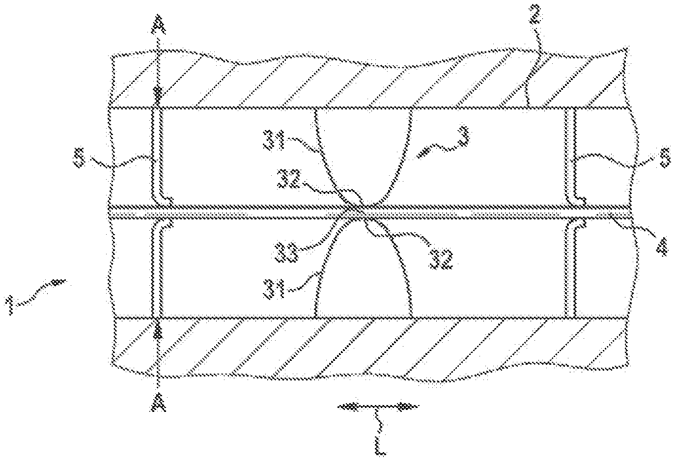
[0023] FIG. 1 shows a perspective diagram of the line penetration for a building structure element;
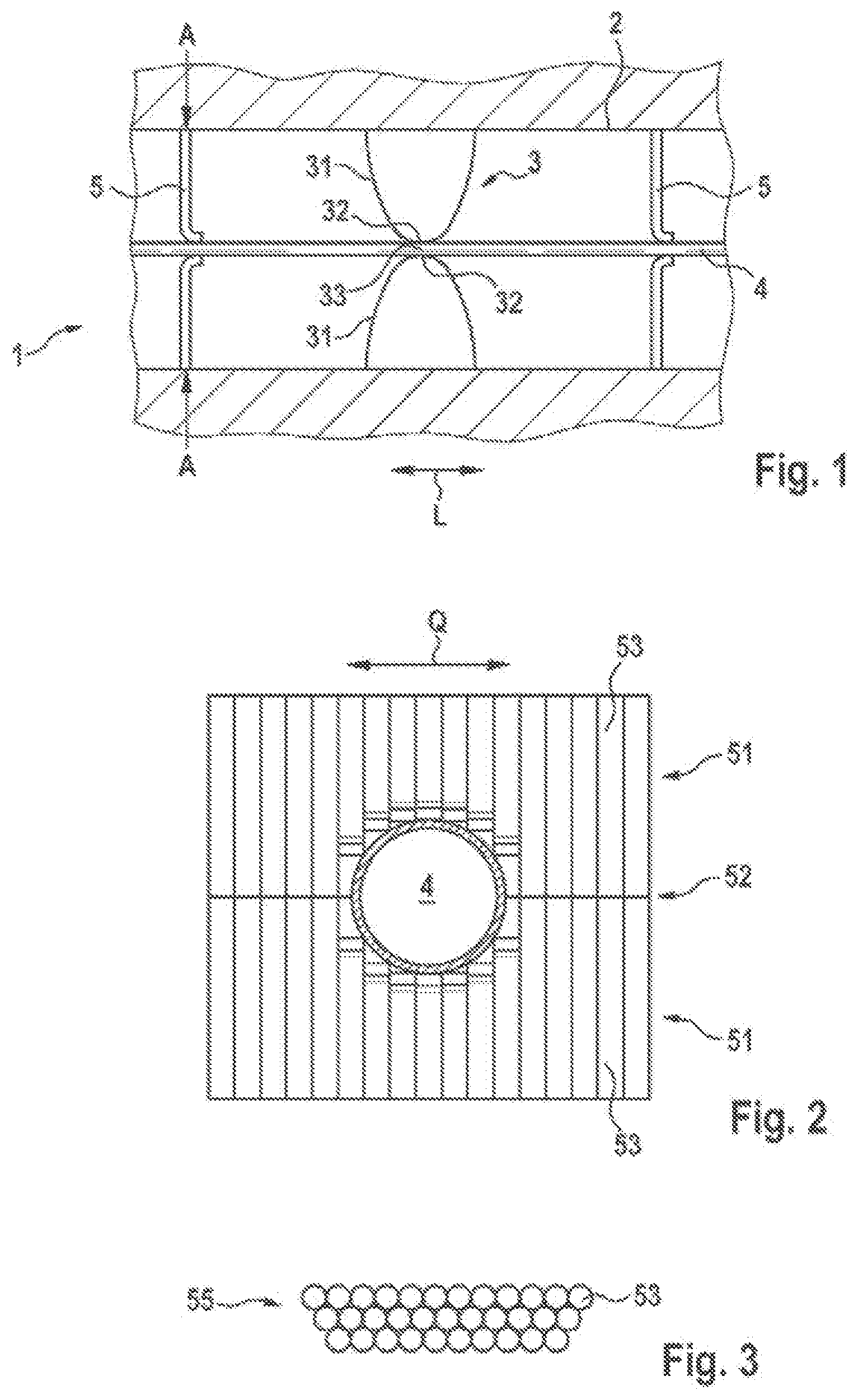
[0024] FIG. 2 shows an overhead view of a sealing arrangement in the line penetration of FIG. 1;
[0025] FIG. 3 shows a cross-sectional diagram of a further sealing arrangement;
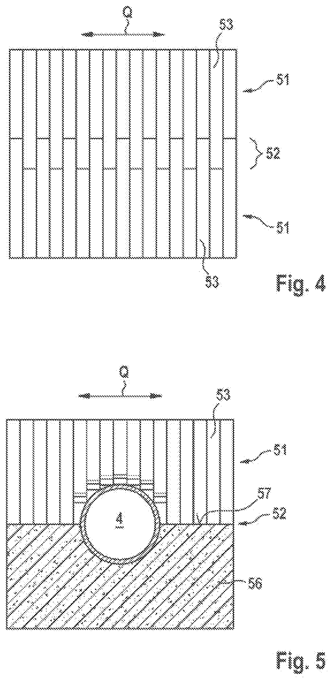
[0026] FIG. 4 shows an overhead view of a sealing arrangement in the line penetration according to a further embodiment; and
[0027] FIG. 5 shows an overhead view of a sealing arrangement in the line penetration according to a further embodiment.
DESCRIPTION OF EMBODIMENTS
[0028] FIG. 1 shows a cross-sectional diagram through a line penetration 1. Line penetration 1 is used for routing of one or more lines 4, such as power lines, water lines, gas lines and the like, for example, through a building structure part, such as a building wall, a ceiling and a floor, for example.
[0029] For this purpose, line penetration 1 is provided with a penetration element 2, which has substantially hollow-cylindrical construction and thus forms a passage opening for routing lines 4 through along a longitudinal direction L of the passage opening. The cross section of penetration element 2 may be circular or rectangular.
[0030] A retaining device 3, which in particular may be disposed in a middle region (relative to longitudinal direction L of the passage opening) of penetration element 2, is disposed in penetration element 2. Retaining device 3 is used for acting on penetrating line 4 with a retaining force that acts transversely relative to the longitudinal direction of penetrating line 4, so that this is held frictionally relative to axial displacement.
[0031] Retaining device 3 is provided with two flexible retaining elements 31, which are turned toward one another, which are deformed by the thickness of a line 4 routed through them and which exert, on penetrating line 4, a force transverse to longitudinal direction L that holds line 4 against slipping. Retaining elements 31 respectively have an elongated retaining edge 32 and in this way define a retaining region 33 extending in transverse direction Q, transversely relative to longitudinal direction L.
[0032] Furthermore, sealing arrangements 5 are disposed offset in longitudinal direction L relative to retaining device 3, in order to prevent passage of fire gases and smoke through penetration element 2.
[0033] In conjunction with FIG. 2, which shows a cross-sectional diagram along section line A-A, a possible structure of sealing arrangement 5 will be explained in more detail. Sealing arrangement 5 is provided with two sealing structures 51 situated opposite one another. Sealing structures 51 are disposed on two oppositely situated regions of the inner wall of penetration element 2 in a manner oriented in transverse direction Q. In the shown embodiment, sealing structures 51 are provided with elastic lamellas 53 directly adjacent to one another, the respective first end of which is fastened to the inner wall in question of penetration element 2, so that lamellas 53 extend into the interior of penetration element 2. The respective second ends of lamellas 53 are located in a passage region 52.
[0034] Lamellas 53 respectively have lengths such that they respectively bear on one another with or in the region of their second ends and thus prevent passage of fire gases and smoke through passage region 52.
[0035] In a portion of passage region 52 in which line 4 is routed through sealing arrangement 5, lamellas 53 are bent over in longitudinal direction L in the region of their second ends and thus bear on the shell surface of line 4 and seal it against passage of fire gases and smoke. In order to achieve reliable sealing, the width of lamellas 53 in transverse direction Q should be much smaller than the diameter (or the dimension in transverse direction) of line 4; in particular, the width of lamellas 53 in transverse direction should be smaller by the factor 5, preferably by the factor 10, than the diameter (or the dimension in transverse direction) of line 4. The thickness of lamellas 53 in longitudinal direction may amount to between 0.5 mm and 5 mm, preferably between 1 mm and 3 mm. Sealing structures 51 may comprise several arrangements of lamellas 53 disposed directly one behind the other in longitudinal direction L.
[0036] Lamellas 53 may have a rectangular cross section, so that adjacent lamellas 53 bear on one another with their side faces, in order to achieve imperviousness even relative to passage between lamellas 53.
[0037] Alternatively, lamellas 53 may also be designed as bristles with round cross sections and may have several layers in longitudinal direction L, so that in this way they form a brush structure 55. The bristles of this brush structure 55 preferably bear on one another, in order in this way to ensure adequate imperviousness relative to the passage of fire gases and smoke. In particular, the bristles of brush structure 55 may bear against one another with a packing density that is as high as possible, so that an arrangement such as illustrated by way of example in FIG. 3 is provided in a cross-sectional view relative to the direction of extension of the bristles. For this purpose, several parallel rows of bristles touching one another are respectively disposed offset relative to one another by the radius of the bristles, wherein the bristles of adjacent rows likewise bear on one another.
[0038] Lamellas 53 or the bristles are preferably formed from an elastic synthetic material. Furthermore, it is also possible to provide woven fabrics, scrims or paper materials, which are flexible, can be laid snugly on the shell surface of line 4 and if possible exert an elastic force on the shell surface, in order to ensure the best possible sealing closure in the region around the shell surface of the line. Lamellas 53 may further be provided with an intumescent material, such as be coated with an intumescent material, for example, or may enclose an intumescent material, and especially may comprise paper equipped with intumescent material.
[0039] As shown in FIG. 4, lamella arrangements 51 may also be provided with lamellas 53 of different length, so that second ends of lamellas 53 respectively situated opposite one another bear on one another at places that along transverse direction Q are offset in a direction of extension E of lamellas 53. Thereby a broadened passage region 52 is obtained. This permits better bearing on penetrating line 4.
[0040] FIG. 5 shows a cross-sectional diagram through a sealing arrangement 5 according to a further embodiment, wherein several sealing structures are provided. A first sealing structure 51 is constructed as described in the foregoing and correspondingly has a lamella arrangement of lamellas 53, which are adjacent to one another and extend in transverse direction Q of passage region 52. The second ends of lamellas 53 bear on a second sealing structure 56, which is provided with a through-going flexible sealing element having a contact face 57 extending in transverse direction Q. Passage region 52 is formed by the bearing of the second ends of lamellas 53 on contact face 57 of the through-going sealing element of second sealing structure 56.
[0041] Second sealing structure 56 is formed from an elastically deformable material, such as a foam or the like, for example, which in particular is provided with an intumescent material. The elastically deformable material of the through-going sealing element and the elastic material of the lamellas as well as their geometric dimensioning are chosen such that, when line 4 is routed through, these are forced by approximately half of their cross section into the elastically deformable material of second sealing structure 56 and thereby deform it.
[0042] During routing of a line 4, part of line 4 deforms elastically deformable through-going sealing element 56, whereas the part of the line cross section projecting out of second sealing structure 56 is surrounded by lamellas 53, in such a way that these bear with their second ends on the shell surface of line 4. In this way, sealing against fire gases and smoke can be achieved, since every part of the shell surface is in contact with a sealing structure 51.
[0043] In order to achieve improved sealing of sealing structures 51 formed with lamellas 53, the lamellas of first sealing structure 51 may be designed with changing elasticity, to the effect that the material of lamellas 53 has smaller elasticity at their fastening to penetration element 2 than at their second end. In other words, the stiffness of lamellas 53 decreases toward their second ends. Thus a penetrating line 4 deforms lamellas 53 substantially at its shell surface, wherein the bent-over portion of lamellas 53 is then in contact with the shell surface in longitudinal direction L. This permits particularly good sealing against fire gases and smoke.
* * * * *
D00000
D00001
D00002
XML
uspto.report is an independent third-party trademark research tool that is not affiliated, endorsed, or sponsored by the United States Patent and Trademark Office (USPTO) or any other governmental organization. The information provided by uspto.report is based on publicly available data at the time of writing and is intended for informational purposes only.
While we strive to provide accurate and up-to-date information, we do not guarantee the accuracy, completeness, reliability, or suitability of the information displayed on this site. The use of this site is at your own risk. Any reliance you place on such information is therefore strictly at your own risk.
All official trademark data, including owner information, should be verified by visiting the official USPTO website at www.uspto.gov. This site is not intended to replace professional legal advice and should not be used as a substitute for consulting with a legal professional who is knowledgeable about trademark law.