Tendon Anchorage And Construction Method Of A Pre-stressed Concrete Structure
TANAKA; Yoshihiro ; et al.
U.S. patent application number 17/498538 was filed with the patent office on 2022-04-14 for tendon anchorage and construction method of a pre-stressed concrete structure. This patent application is currently assigned to TOKYO ROPE MANUFACTURING CO., LTD.. The applicant listed for this patent is TOKYO ROPE MFG. CO., LTD.. Invention is credited to Masaki ONO, Yoshihiro TANAKA.
| Application Number | 20220112718 17/498538 |
| Document ID | / |
| Family ID | |
| Filed Date | 2022-04-14 |


| United States Patent Application | 20220112718 |
| Kind Code | A1 |
| TANAKA; Yoshihiro ; et al. | April 14, 2022 |
TENDON ANCHORAGE AND CONSTRUCTION METHOD OF A PRE-STRESSED CONCRETE STRUCTURE
Abstract
An anchorage includes a bearing plate arranged in an end portion of a concrete structure with an insertion hole formed therein and formed with a through hole connecting to the insertion hole. A sleeve is inserted through the insertion hole and the through hole, with one end portion of the sleeve disposed on the outside of the structure. A tendon is inserted within the sleeve, with one end portion of the tendon disposed on the outside of the structure. A locknut is engaged with the one end portion of the sleeve and in contact with the outer surface of the bearing plate. A PC grout fills the insertion hole and the sleeve. Before filling, the tendon is applied with tension and, after strength expression of the PC grout, the tension is released. The tendon undergoes a Poisson effect to expand radially outward and compression stress occurs in the PC grout.
| Inventors: | TANAKA; Yoshihiro; (Tokyo, JP) ; ONO; Masaki; (Tokyo, JP) | ||||||||||
| Applicant: |
|
||||||||||
|---|---|---|---|---|---|---|---|---|---|---|---|
| Assignee: | TOKYO ROPE MANUFACTURING CO.,
LTD. Tokyo JP |
||||||||||
| Appl. No.: | 17/498538 | ||||||||||
| Filed: | October 11, 2021 |
| International Class: | E04C 5/12 20060101 E04C005/12 |
Foreign Application Data
| Date | Code | Application Number |
|---|---|---|
| Oct 13, 2020 | JP | 2020-172522 |
Claims
1. A tendon anchorage comprising: a bearing plate arranged in an outer end portion of a concrete structure with an insertion hole formed therein and formed with a through hole connecting to the insertion hole of the concrete structure; a hollow sleeve inserted through the insertion hole of the concrete structure and the through hole of the bearing plate, one end portion of the sleeve put on the outside of the concrete structure; a tendon inserted within the sleeve, one end portion of the tendon fixed to the concrete structure and the other end portion of the tendon put on the outside of the concrete structure; a locknut engaged with the other end portion of the sleeve, which is put on the outside of the concrete structure, and in contact with the outer surface of the bearing plate; and PC grout filling the insertion hole and the sleeve, wherein before filling with the PC grout, the other end portion of the tendon is pulled outward by a tensioning device with the one end portion being fixed so that the tendon is applied with tension and, after expression of a predetermined strength in the PC grout, the tension is released by the tensioning device, and the tendon undergoes a Poisson effect to expand radially outward and compression stress occurs in the PC grout between the expanding tendon and the sleeve.
2. The tendon anchorage according to claim 1, wherein the tendon is a continuous fiber-reinforced polymer strand.
3. The tendon anchorage according to claim 1, wherein a hollow sheath tube is embedded in the concrete structure, and the hollow space of the sheath tube is used as the insertion hole.
4. The tendon anchorage according to claim 1, wherein the compression stress p occurring in the PC grout and calculated by the following equation 1 is 20 to 60 MPa: p=.phi./2.times.v.times.(0.7.times..epsilon.u).times.(t.times.E)/(R.times- .R) (Eq.1), where .phi., v, .epsilon.u, R, t, and E represent, respectively, the diameter of the tendon, Poisson's ratio of the tendon, tensile strain with guaranteed ultimate load of the tendon, inner radius of the sleeve, thickness of the sleeve, and elastic coefficient of the sleeve.
5. The tendon anchorage according to claim 1, wherein at least one of the inner surface and the outer surface of the sleeve is made concavo-convex.
6. The tendon anchorage according to claim 1, wherein the bearing plate arranged in the outer end portion of the concrete structure consists of a single continuous plate, not plural plates.
7. The tendon anchorage according to claim 1, wherein a plurality of convex shear keys are provided on a surface of the bearing plate opposed to the concrete structure, and recesses that the shear keys enter are formed in positions corresponding to those of the shear keys on a surface of the concrete structure opposed to the bearing plate.
8. A tendon anchorage comprising: a pair of locknut-and-bearing-plates arranged, respectively, in the end portions within a concrete structure and each formed with a through hole; a hollow sleeve engaged with each of the pair of locknut-and-bearing-plates and connecting to the through holes; a tendon inserted through the through hole of each of the locknut-and-bearing-plates in the end portions within the concrete structure and the hollow sleeve, the end portions of the tendon put on the outside of the concrete structure; and PC grout filling the sleeve, wherein before the PC grout filling the sleeve and concrete forming the concrete structure being placed, with one end portion of the tendon being fixed using a fixing device, the other end portion of the tendon is pulled outward by a tensioning device so that the tendon is applied with tension and, after expression of a predetermined strength in the PC grout and the concrete, the tension is released by the tensioning device, and the tendon undergoes a Poisson effect to expand radially outward and compression stress occurs in the PC grout between the expanding tendon and the sleeve.
9. The tendon anchorage according to claim 8, wherein the tendon is a continuous fiber-reinforced polymer strand.
10. The tendon anchorage according to claim 8, wherein the compression stress p occurring in the PC grout and calculated by the following equation 1 is 20 to 60 MPa: p=.phi./2.times.v.times.(0.7.times..epsilon.cu).times.(t.times.E)/(R.time- s.R) (Eq.1), where .phi., v, .epsilon.u, R, t, and E represent, respectively, the diameter of the tendon, Poisson's ratio of the tendon, tensile strain with guaranteed ultimate load of the tendon, inner radius of the sleeve, thickness of the sleeve, and elastic coefficient of the sleeve.
11. The tendon anchorage according to claim 8, wherein at least one of the inner surface and the outer surface of the sleeve is made concavo-convex.
12. The tendon anchorage according to claim 8, wherein the sleeve is formed with a filling hole for the PC grout to fill the sleeve and an air discharge hole for air to be discharged.
13. A construction method of a pre-stressed concrete structure using a post-tensioning system, comprising: arranging, in an end portion of a concrete structure with an insertion hole formed therein, a bearing plate with a through hole connecting to the insertion hole of the concrete structure; engaging a locknut with one end portion of a hollow sleeve; inserting the sleeve through the through hole of the bearing plate into the insertion hole of the concrete structure and placing the locknut engaged with the one end portion of the sleeve on the bearing plate; inserting a tendon into the sleeve; fixing one end portion of the tendon; placing a tensioning device in the other end portion of the tendon; with the tendon being applied with tension, filling the insertion hole of the concrete structure with PC grout such that the PC grout also fills the clearance gap between the sleeve and the tendon inserted into the sleeve; and after the PC grout reaching a predetermined strength, releasing the tension within the tendon.
14. A construction method of a pre-stressed concrete structure using a pre-tensioning system, comprising: providing a formwork; installing, in each lateral end portion within the formwork, a hollow sleeve and a locknut-and-bearing-plate engaged with the sleeve such that the locknut-and-bearing-plate comes into contact with each lateral end portion within the formwork; inserting a tendon through installation holes formed in the lateral end portions of the formwork into the formwork and putting the end portions of the tendon out through the respective lateral end portions of the formwork, while within the formwork, inserting the tendon into the sleeve installed in each lateral end portion within the formwork; placing a fixing device in one end portion of the tendon put out of the formwork through one lateral end portion of the formwork; placing a tensioning device in the other end portion of the tendon put out of the formwork through the other lateral end portion of the formwork; applying the other end portion of the tendon with tension using the tensioning device; with the tendon being applied with the tension, filling the sleeve in each lateral end portion within the formwork with PC grout; placing concrete within the formwork; and after the PC grout and the concrete reaching a predetermined strength, releasing the tension within the tendon.
Description
CROSS REFERENCE TO RELATED APPLICATION
[0001] This U.S. Patent Application claims the benefit of and priority to JP Patent Application 2020-172522 filed on Oct. 13, 2020, the entire disclosure of the application being considered part of the disclosure of this application and hereby incorporated by reference.
BACKGROUND OF THE INVENTION
1. Field of the Invention
[0002] The present invention relates to a tendon anchorage and a construction method of a pre-stressed concrete structure. The tendon anchorage according to the present invention is applicable to both a pre-stressed concrete structure fabricated (constructed) using a post-tensioning system and a pre-stressed concrete structure fabricated using a pre-tensioning system.
2. Background Art
[0003] Applying a continuous fiber-reinforced polymer strand as a tendon for a pre-stressed concrete structure has conventionally brought more advantages than adapting a related-art PC steel strand as a tendon. The most important advantage is that the continuous fiber-reinforced polymer strand cannot get rusted and can be less likely to be deteriorated even under a rigorous environment. In addition, among continuous fiber-reinforced polymer strands, a continuous carbon fiber-reinforced polymer strand has an ultimate tensile stress of about 3600 N/mm.sup.2, while a PC steel strand has an ultimate tensile stress of about 1300 N/mm.sup.2, the former having a tensile strength about 2.8 times higher than that of the latter. Further, the continuous carbon fiber-reinforced polymer strand has a material weight per unit ultimate load and per unit length of 0.76 g/m/kN, while the PC steel strand has of 4.23 g/m/kN, proving that the former is about 1/5.6 lighter than the latter. Accordingly, the continuous carbon fiber-reinforced polymer strand with a smaller cross-sectional area than a PC steel strand can be arranged upon introducing pre-stress into concrete and also can be worked with reduced construction time and effort.
[0004] In terms of maintaining durability of a pre-stressed concrete structure, recent facilities have been planned to evaluate a life cycle cost including not only an initial construction cost of a concrete structure but also a maintenance cost. In this context, there has been a trend in which applying a continuous carbon fiber-reinforced polymer strand as a tendon is also put in perspective of considerations.
[0005] However, to apply a continuous fiber-reinforced polymer strand as a major tendon, there have been problems to be solved. One of the problems relates to an anchorage system of a continuous fiber-reinforced polymer strand applied as a tendon. There has conventionally been employed a construction method in which with a steel wedge and an anchor head, a PC steel strand is gripped directly at its any position and introduced with a tensioning force using a tensioning jack and/or anchored to a bearing plate via the anchor head. The most important advantage of this construction method is its technical superiority in, for example, that the steel wedge can be used for gripping and releasing the PC steel strand at its any position and that the steel wedge and the anchor head can introduce, as a small-sized arrangement, a strong tensioning force into the pre-stressed concrete structure, thus having made a great contribution in working a pre-stressed concrete structure with a PC steel strand applied thereto.
[0006] That is, the combination of a PC steel strand and a steel wedge causes the surface of the steel wedge in a portion in contact with the PC steel strand to be processed in a concavo-convex manner to bite the surface of the PC steel strand due to its wedge effect, whereby the PC steel strand and the steel wedge can be kept in a gripped state for transmission of a tensioning force to the anchor head.
[0007] On the other hand, it is not possible to apply a steel wedge and an anchor head, which are applied to a PC steel strand, directly as an anchorage for a continuous fiber-reinforced polymer strand, which has superior characteristics as a tendon. When a steel wedge equivalent to one applied to a PC steel strand is applied to a continuous fiber-reinforced polymer strand, the surface of the steel wedge can bite the surface of the continuous fiber-reinforced polymer strand due to its wedge effect, but no shear resistance is expected in the bitten portion of the continuous fiber-reinforced polymer strand. This cannot be applied as an anchorage because, for example, the surface of the continuous fiber-reinforced polymer strand is extremely soft and may be easily scraped off in the bitten portion or, if the wedge bites a larger portion, the continuous fiber-reinforced polymer strand may be cut off, whereby no gripping effect is expected.
[0008] The following two types of anchoring structural techniques are currently and practically implemented as anchorages for the continuous fiber-reinforced polymer strand. One of the anchoring structures employs a system in which a buffer material is wound around the continuous fiber-reinforced polymer strand and a wedge is applied thereon. A steel wedge is applied, though having a length greater than a steel wedge for a PC steel strand to adjust the wedge taper angle and requiring to use a dedicated jack for push-in to the anchor head, placing limiting conditions to work. This is therefore used as a connection jig between a pre-tensioning PC steel strand and a continuous fiber-reinforced polymer strand because it cannot be applied for a post-tensioning tendon.
[0009] An anchorage of an expansion agent filling type fabricated by filling a steel pipe sleeve with expansion agent has successfully been employed to apply a continuous fiber-reinforced polymer strand as a post-tensioning tendon. The basic principle of this anchorage is to utilize the continuous fiber-reinforced polymer strand and the expansion-compression stress of the expansion agent filling the steel pipe sleeve to increase the shear resistance between the continuous fiber-reinforced polymer strand and the steel pipe sleeve. This anchoring system can be applied to both fixed end anchorage and tension stressing end anchorage in case of a post-tension work. It is, however, necessary to control temperature and humidity for the strength and the expansion check after filling of the expansion agent, which requires factory production. Upon shipment from the factory, the length of the continuous fiber-reinforced polymer strand and the anchoring position of the expansion agent-type anchorage are fixed.
[0010] Japanese Patent Application Publication No. H9-53325 discloses connection and traction with a related-art large-sized connecting member to solve a problem of increase in the injection of mortar. That is, synthetic resin material or anchoring expansion material to be cured within a socket is injected into an intermediate portion of a fiber composite strand to provide an anchoring body that is integrated with the fiber composite strand via thus cured synthetic resin material or anchoring expansion material and, after tensioning, to be anchored to a structure through the intermediate anchoring body.
[0011] It is publicly known that a method of injection synthetic resin material or anchoring expansion material into a clearance gap between a socket and a fiber composite strand can provide a structure of an anchoring body. While the method disclosed in Japanese Patent Application Publication No. H9-53325 requires the intermediate anchoring body to be localized and place before tensioning, actual tensioning operations undergo a change in the stretch of the fiber composite strand due to tensioning because the length of the structure is different from that in the design drawing and/or various frictional resistances occur during tensioning. Accordingly, the invention of Japanese Patent Application Publication No. H9-53325 is not practical in that it is necessary to pre-install the intermediate anchoring body.
[0012] Japanese Patent Application Publication No. 2005-76388 discloses a fixed end anchorage for a high-strength fiber composite cable to be processable not in factory but on site, in which a collapsible buffer partitioning material with through holes for expansive filling material to pass therethrough and for a cable to be inserted therethrough is provided in an intermediate portion of a sleeve to equalize the expansion pressure of the expansive filling material in the length direction. However, the theoretical development in Japanese Patent Application Publication No. 2005-76388 comes under some questions. One of the questions resides in the description "This requires an expansion pressure of 50 MPa or higher, . . . requiring installation and temperature control." described in paragraph [0017]. Expansion/compression stress by the expansive material occurs only if expansive strain resides within the expansion material and the inner diameter, thickness, and elastic coefficient of a sleeve in which the expansive strain is confined is determined. Extremely speaking, no expansion pressure occurs in the expansive material unless there is a sleeve or some other confining means.
[0013] There is a similar description in paragraph [0019] "According to an experiment, it was proven that under a condition of natural cure, an expansion pressure of 30 MPa could be achieved with a void of a size one to three times the cross-sectional area of a cable". Also, the description does not indicate, under a natural condition (on-site cure), how the expansive strain of the expansion material is, but only that the expansion pressure is 30 MPa. The description "one to three times the cross-sectional area of a cable" only indicates information about the inner diameter of the sleeve in which the expansive strain is confined, without information about the thickness and elastic coefficient of the sleeve and the expansive strain of the expansion material, resulting in a lack of theoretical consistency.
[0014] International Publication No. WO 2011/019075 discloses a carbon fiber reinforced plastic cable covered with a frictional sheet with abrasive particles adhering thereto and a steel blade net tube thereon to allow for wedge anchoring. An anchorage obtained by combining a sleeve and an expansive material, which has conventionally been practiced as an anchorage for a continuous fiber-reinforced polymer strand, is fixed in its position because of being predicated on factory production. This system suffers from no problem as an anchoring body for tensioning at a fixed end anchorage. It is, however, difficult to apply this system to a tension stressing end anchorage because such an anchorage as fabricated preliminarily in a factory fluctuates in its position. In the invention of WO 2011/019075, since the frictional sheet and the blade net can be wound at any position to place a wedge, it is possible to set any position for tensioning by a tensioning jack. However, a steel wedge, which is applied to a PC steel strand, can practically grip the PC steel strand at any position. On the other hand, in the method disclosed in WO 2011/019075, portions reinforced by the frictional sheet and the steel blade net tube can only be gripped. Further, in order for the wedge to grip the continuous fiber-reinforced polymer strand with the frictional sheet and the blade net wound therearound, another support by a wedge push-in jack is also required, which causes a substantial problem in a tensioning operation using a tensioning jack. It is therefore difficult to apply the method disclosed in WO 2011/019075 to an anchoring body at a tension stressing end anchorage. This technique is directed to pre-tensioning and utilized as a connection jig between a continuous fiber-reinforced polymer strand and a related-art PC steel strand installed at a tension stressing end anchorage.
[0015] The system for introducing pre-stress into a concrete structure using a tensioning force in a PC steel strand includes a post-tensioning system and a pre-tensioning system. The tension introducing system that applies a continuous fiber-reinforced polymer strand also includes a post-tensioning system and a pre-tensioning system. For each of the systems, problems in a related-art system utilizing a continuous fiber-reinforced polymer strand will be provided below.
Post-Tensioning System
[0016] (1) Anchoring of Bearing Plate and Expansion Material Sleeve with Locknut
[0017] In the currently best-applied method of anchoring a continuous fiber-reinforced polymer strand, the clearance gap between the continuous fiber-reinforced polymer strand and a sleeve is filled with expansion material (using cement-based expansion material) to utilize expansion/compression stress that occurs when the expansion material expands during its hydration process. The anchoring mechanism utilizes expansion/compression stress between the continuous fiber-reinforced polymer strand and the sleeve to increase the contact compression stress against the distortional shear force acting between the outer surface of the continuous fiber-reinforced polymer strand and the inner surface of the sleeve for reliable anchoring of the continuous fiber-reinforced polymer strand within the sleeve.
[0018] The above-described method that applies an expansion material sleeve is commonly and frequently employed in which after tensioning on the tensioning side, the tensioning force is anchored to the bearing plate provided at an end portion of the concrete structure. In this method, a locknut is placed on the exterior of the expansion material sleeve to eventually transmit the tensioning force to the bearing plate. For this purpose, the exterior of the sleeve is cut the screw so that the locknut can work. A screw hole is also provided at the end portion of the expansion material sleeve into which a screwed tension bar can be connected to pull out the expansion material sleeve by tensioning jack. The expansion material sleeve is tensioned via the tension bar using a center hole jack and, after reaching a predetermined tensioning force, a locknut preliminarily placed on the expansion material sleeve is fastened to the bearing plate so that the tensioning force is transmitted to the bearing plate and thereby tensioning stress occurs in the concrete structure. The sheath is then filled with PC grout and the series of tensioning operations ends with PC grout strength indication.
[0019] First Problem: the current method of anchoring a tensioning force to the bearing plate via the locknut on the expansion material sleeve puts a limitation on the length of the concrete structure to be tensioned. In a common design rule, the tensioning force upon tensioning of the continuous fiber-reinforced polymer strand is set out to be 70% or less of the guaranteed ultimate load capacity. That is, irrespective of the diameter of the continuous fiber-reinforced polymer strand used, the tensile strain of the continuous fiber-reinforced polymer strand upon tensioning is 11,000.mu. to 12,000.mu.. If the tensioning member has a length of L=10 m, the deformation by tensioning is .DELTA.L=110 mm to 120 mm. On the other hand, since the expansion material sleeve generally has a length of 300 to 400 mm at the longest, the continuous fiber-reinforced polymer strand has a length of about 15 m to 20 m at the longest, in view of the handling during anchoring.
[0020] Second Problem: the expansion material sleeve onto which the locknut is placed generally has an outer diameter greater than the tube diameter of the sheath. Accordingly, at the start of tensioning, the end portion of the expansion material sleeve near the bearing plate is on the outside of the bearing plate. This causes the expansion material sleeve to protrude 300 to 400 mm from the tensioning end portion when the locknut is fixed to the bearing plate after tensioning. Also, in related-art anchoring of a PC steel strand at an end portion, the anchor head may protrude from the end portion. It is generally not desirable for a member playing a critical role in tensioning control to protrude significantly from the tensioning end anchorage portion. It is naturally necessary to be equipped with a covering arrangement for management.
[0021] Third Problem: the expansion material sleeve is commercialized by being filled with expansive cement-based material to control expansion during hydration. This requires quality control such as temperature and humidity control in factory, so that factory production is only allowed. The structure into which pre-stress is introduced utilizing a tensioning force in a tendon is a concrete structure and, if it is, for example, a bridge, generally has a length of 30 m to 50 m, and an error of 0.5% occurring in the length direction can result in an error of 150 mm to 250 mm in total length. Additionally, a pre-cast concrete, if joined, has a very high product accuracy, while the joint portion is operated on-site and may have an accumulative error. In view of such a case where an error may occur in the length of an intended structure into which pre-stress is introduced, it is difficult to produce an expansion material sleeve in a factory in advance. It is noted that a related-art PC steel strand cannot suffer from such a problem as described above because it basically undergoes wedge anchoring and therefore the tendon is cut on-site as well as the anchoring may be made at any position.
(2) Method Without Tension Stressing End Anchorage in Post-Tensioning System
[0022] This is not implemented in a post-tensioning system for anchoring a common PC steel strand, but employed in a tendon system using a continuous fiber-reinforced polymer strand, in which a sheath tube is filled with PC grout with a tensioning force held after tension stressing and, after PC grout strength indication, the tensioning force of the tendon of the continuous fiber-reinforced polymer strand is released. This concept is based on the method of generation of a tensioning force in the pre-tensioning system. In the pre-tensioning system, concrete is placed with a tensioning force in a tendon held and, after the concrete strength indication, the tendon is released to introduce pre-stress into the concrete structure. In this case, when the tensioning force in the PC steel strand is released, the tensile strain acting on the PC steel strand in the axial direction (longitudinal direction) undergoes a Poisson effect, and expansive strain occurs in the diameter direction (lateral direction) of the tendon. In comparison, since the concrete placed around the PC steel strand serves as a confining material, compression stress occurs between the surface of the PC steel strand and the concrete as a reaction force against the confinement effect, resulting in an increase in the shear or bond resistance for slipping between the concrete and the PC steel strand.
[0023] Also, in a post-tensioning system using a continuous fiber-reinforced polymer strand, since PC grout filling the interior of the sheath tube serves as a confining material, when the tensioning force is released, confining compression stress occurs on the surface of the continuous fiber-reinforced polymer strand, resulting in an increase in the shear resistance. In the post-tensioning system using a related-art PC steel strand, a method of releasing a tip end of the PC steel strand without tension anchoring using a bearing plate and/or an anchor head is not employed for the reason that the surface of the PC steel strand is smooth and has a poor adhesive characteristic with PC grout. On the other hand, the continuous fiber-reinforced polymer strand is less likely to be adhered with PC grout than a rebar, but more likely than a PC steel strand.
[0024] First Problem: after tension introduction, no tensioning force is transmitted via a locknut to a bearing plate, so that no pre-stress occurs in the concrete in the vicinity of the tensioning end portion. Even when the above-described Poisson effect may cause a shear resistance to work between the continuous fiber-reinforced polymer strand and the PC grout, no pre-stress is expected within the range of 50.phi. to 60.phi. from the tension stressing end portion (.phi. represents the diameter of the continuous fiber-reinforced polymer strand). It is therefore difficult to apply this method when pre-stress is required up to around the end portion of the concrete structure.
[0025] Second Problem: the first problem above specifically means that it is difficult to introduce tensioning stress into a small-sized concrete structure. Specifically, when a continuous fiber-reinforced polymer strand of, for example, .phi.=15.2 mm is used, the range within which sufficient tensioning stress is not expected is 60.phi.=912 mm. The above-described anchoring method cannot be applied to a structure having a length of, for example, 3 m to 4 m.
Pre-Tensioning System
[0026] The mechanism of tensioning stress introduction in a pre-tensioning system is as described above. Accordingly, even when a continuous fiber-reinforced polymer strand may be used as a tendon, if concrete placed after tensioning reaches a predetermined strength and introduces tensioning stress, there is a problem that the vicinity of the tension stressing end portion (at a distance of 50.phi. to 60.phi.) is not introduced with tensioning stress. It is therefore difficult to introduce pre-stress into a short member in a pre-tensioning system, including the case of a pre-tensioning system using a related-art PC steel strand.
[0027] PC steel strands have conventionally been applied frequently as tendons. The advantage of PC steel strands is that with a steel wedge and an anchor head, a PC steel strand is gripped directly at its any position and introduced with a tensioning force using a tensioning jack and/or anchored to a bearing plate via the anchor head, whereby pre-stress can be introduced up to around the tensioning end portion.
[0028] On the other hand, a continuous fiber-reinforced polymer strand to which the present invention is directed is formed by processing polymer strands of, for example, carbon fiber, aramid fiber, glass fiber, or the like into a rope. Such a continuous fiber-reinforced polymer strand thus has reduced lateral rigidity and/or strength and cannot be anchored with a steel wedge as before.
[0029] Accordingly, an anchoring method that utilizes expansion/compression stress of an expansion material filling the clearance gap between a sleeve and a continuous fiber-reinforced polymer strand and cured there is currently applied most frequently for anchoring of a continuous fiber-reinforced polymer strand and in widespread use as a practical method.
[0030] Another anchoring method is also applied in which a continuous fiber-reinforced polymer strand is reinforced with a friction enhancing sheet and a steel blade net tube therearound and, on the outside thereof, applied with a steel wedge having a wedge angle looser than that of a related-art steel wedge. However, this method is limited in its manner of operation and therefore has problems to be applied at the tension stressing end portion.
SUMMARY OF THE INVENTION
[0031] In view of the current situations above, it is an object of the present invention to provide an anchorage with neither site-operational limitation nor working cost increase, including a simple anchoring mechanism and a structure in which a sleeve, a locknut, and a bearing plate can be designed with common structural computation.
[0032] It is another object of the present invention to anchor a tendon reliably to a concrete structure to efficiently introduce pre-stress into the concrete structure.
[0033] The present invention provides a tendon anchorage in a concrete structure into which pre-stress is introduced using a post-tensioning system. The tendon anchorage according to a first aspect of the invention includes a bearing plate arranged in an outer end portion of a concrete structure with an insertion hole formed therein and formed with a through hole connecting to the insertion hole of the concrete structure, a hollow sleeve inserted through the insertion hole of the concrete structure and the through hole of the bearing plate, one end portion of the sleeve put on the outside of the concrete structure, a tendon inserted within the sleeve, one end portion of the tendon anchored to the concrete structure and the other end portion of the tendon put on the outside of the concrete structure, a locknut engaged with the other end portion of the sleeve, which is put on the outside of the concrete structure, and in contact with the outer surface of the bearing plate, and PC grout filling the insertion hole and the sleeve, in which before filling with the PC grout, the other end portion of the tendon is pulled outward by a tensioning device with the one end portion being fixed so that the tendon is applied with tension and, after expression of a predetermined strength in the PC grout, the tension is released by the tensioning device, and the tendon undergoes a Poisson effect to expand radially outward and compression stress occurs in the PC grout between the expanding tendon and the sleeve.
[0034] One end portion (fixed end anchorage) of the tendon is fixed to the concrete structure and the other end portion (tension stressing end anchorage) of the tendon is pulled outward by the tensioning device. The one end portion of the tendon may be anchored by a fixing device on the outside of the concrete structure or may be anchored to the concrete structure using, for example, PC grout within the insertion hole.
[0035] The present invention also provides a tendon anchorage in a concrete structure into which pre-stress is introduced using a pre-tensioning system. The tendon anchorage according to a second aspect of the invention includes a pair of locknut-and-bearing-plates arranged, respectively, in the end portions within a concrete structure and each formed with a through hole, a hollow sleeve engaged with each of the pair of locknut-and-bearing-plates and connecting to the through holes, a tendon inserted through the through hole of each of the locknut-and-bearing-plates in the end portions within the concrete structure and the hollow sleeve, the end portions of the tendon put on the outside of the concrete structure, and PC grout filling the sleeve, in which before the PC grout filling the sleeve and concrete forming the concrete structure being placed, with one end portion of the tendon being fixed using a fixing device, the other end portion of the tendon is pulled outward by a tensioning device so that the tendon is applied with tension and, after expression of a predetermined strength in the PC grout and the concrete, the tension is released by the tensioning device, and the tendon undergoes a Poisson effect to expand radially outward and compression stress occurs in the PC grout between the expanding tendon and the sleeve.
[0036] The tendon preferably employs a continuous fiber-reinforced polymer strand. The continuous fiber-reinforced polymer strand is formed by bundling several tens of thousands of continuous carbon fibers, aramid fibers, glass fibers, or the like and impregnating with thermosetting resin such as epoxy resin or vinyl ester resin or thermoplastic resin such as polycarbonate or polyvinyl chloride for curing. The continuous fiber-reinforced polymer strand may be formed by bundling several continuous fibers and twisting several continuous fiber bundles.
[0037] Preferably, a hollow sheath tube is embedded in the concrete structure, and the hollow space of the sheath tube is used as the insertion hole.
[0038] In accordance with the present invention, the Poisson effect causes the tendon to expand radially outward and thereby compression stress occurs in the PC grout between the tendon and the surrounding sleeve, whereby the tendon is confined reliably within the sleeve and anchored over the entire periphery within the range surrounded by the sleeve.
[0039] The tendon also contracts in the longitudinal direction (acts to recover its original length) when the tension is released. Since the locknut or the locknut-and-bearing-plates are engaged with one end portion of the sleeve that is anchored reliably with the tendon, when the tension within the tendon is released and the tendon contracts in the longitudinal direction, the locknut engaged with the one end portion of the sleeve that is anchored reliably with the tendon is urged against the bearing plate (post-tensioning system) or the locknut-and-bearing-plates in the end portions within the concrete structure are applied with a force that causes them to come close to each other (pre-tensioning system), whereby pre-stress can be introduced efficiently into the concrete structure.
Principle of Anchoring According to the Invention
[0040] A tendon anchoring mechanism according to the present invention will be briefly described. When the tendon is applied with tension, tensile strain occurs within the tendon in the tensioning direction (in the longitudinal direction of the tendon) and, at the same time, a Poisson effect causes compressive strain to occur in the circumferential direction of the tendon, which is orthogonal to the tensioning direction. With this state being maintained, PC grout fills the clearance gap between the sleeve and the tendon. The PC grout is then cured for expression of a predetermined strength. After strength expression of the PC grout, when the tension within the tendon is released (the tensioning force is released), the circumferential compressive strain existing in the tendon is released. When the compressive strain within the tendon is released, the tendon expands radially outward (Poisson effect, Poisson phenomenon). Compression stress occurs in the PC grout between the expanding tendon and the sleeve, whereby the tendon and the sleeve are tightly anchored to each other.
[0041] The locknut engaged with the anchored sleeve shares a tensioning reaction force, which is introduced via the bearing plate provided in an end portion of the concrete structure into the concrete structure as pre-stress effective over the entire length also including the end portion of the concrete structure.
[0042] It has practically been proven based on the performance of expansion material filling sleeves that when compression stress occurs in PC grout present in the clearance gap between a tendon and a sleeve, an anchoring mechanism occurs between the tendon and the sleeve. Whether or not the foregoing theoretical development is correct will hereinafter be considered quantitatively by calculating compression stress occurring in PC grout when a continuous carbon fiber-reinforced polymer strand is used as a tendon.
Compression Stress Occurring in PC Grout According to the Invention
[0043] The anchoring mechanism will be described by specifically calculating compression stress occurring in PC grout for a continuous carbon fiber-reinforced polymer strand that is formed by applying carbon fiber as a continuous fiber-reinforced polymer strand. The shape and characteristics of the subject continuous carbon fiber-reinforced polymer strand (hereinafter referred to as CFCC (Carbon Fiber Composite Cable) which is a product name) and the sleeve are as follows.
1) Data on CFCC
[0044] The diameter of CFCC .phi.=17.2 mm, effective cross-sectional area of CFCC Acf=151.1 mm.sup.2, elastic coefficient of CFCC Ecf=150 kN/mm.sup.2, guaranteed ultimate load of CFCC Pu=385 kN, Poisson's ratio of CFCC v=0.06 (from carbon fiber reinforced plastic test data by Shimadzu Corporation).
2) Data on Sleeve
[0045] The material of the sleeve is STKM13A, inner radius of the sleeve R=11.4 mm, thickness t=4.5 mm, elastic coefficient of the sleeve E=210 kN/mm.sup.2.
[0046] The maximum tensioning force that can be applied to CFCC when applied with tension is specified 70% or less of the guaranteed ultimate load of CFCC. Accordingly, the tensile strain during tensioning .epsilon.u=0.7.times.Pu/(Acf.times.Ecf)=11,890.mu..
[0047] When the tension within CFCC is released, a Poisson effect causes lateral (circumferential) expansive strain to occur in CFCC in proportion to the Poisson's ratio and thereby CFCC to have an increased diameter. The expansive strain .epsilon.lu=v.times..epsilon.u=713.mu., where .epsilon.lu represents the lateral expansive strain. Accordingly, the expansion of the inner radius R within the sleeve .DELTA.R=.phi./2.times..epsilon.lu=6,132.times.10.sup.-6 mm when a Poisson effect occurs in CFCC from which the tension is released and, as a result, CFCC expands.
[0048] When the inner radius within the sleeve expands by the length .DELTA.R, applying a theoretical solution of "Theoretical Analysis of Inner Pressure Acting on Thin-walled Ring", the compression stress p occurring in the PC grout can be solved as p=.DELTA.R.times.t.times.E/R2=44.6 MPa.
[0049] The relationship between an increase in the compression stress of the PC grout and anchoring of CFCC to the sleeve via the PC grout will hereinafter be described. The performance of anchoring is determined by a combination for minimum resistance among shear fracture stress of the PC grout itself between CFCC and the sleeve, frictional force and adhesion acting at the interface between the PC grout and CFCC, and frictional force and adhesion acting at the interface between the PC grout and the interior of the sleeve.
[0050] First, as for resistive shear stress of the PC grout itself, since the PC grout is very thin in a state where compression stress acts thereon, shear fracture cannot occur. On the other hand, in comparison between the interface between the PC grout and CFCC and the interface between the PC grout and the interior of the sleeve, the former has a resistance area smaller than that of the latter and is likely to have a reduced frictional force, while the interface between the PC grout and CFCC is likely to have increased adhesive stress. In contrast, the latter has a reverse of the relationship above. In any event, shear force acting at the interface with the PC grout is dominated mainly by resistance due to a frictional force, which is derived mainly from compression stress of the PC grout. Since frictional resistance stress is represented by the product of friction coefficient and compression stress acting at the interface, it is advantageous that the PC grout have high compression stress p.
Compression Stress Occurring in Expansion Material of Related-Art Expansion Material Filling Sleeve
[0051] Naturally, a Poisson effect cannot be applied to a related-art expansion material filling sleeve as in the present invention. However, the eventual anchoring mechanism uses, in lieu of PC grout, expansive filler (expansive cement grout) obtained by containing expansive material and utilizes expansion/compression stress that occurs when the grout material expands during its hydration process, which is consequently the same as the mechanism applied upon usage as an anchoring device.
[0052] Upon evaluation of appropriateness of the present invention, the compression stress p occurring in an expansion material filling sleeve, which has already been put into practice, is utilized to provisionally calculate the expansion material compression stress p occurring with the same shape and material of a CFCC tendon and a sleeve as in the present invention.
1) Data on CFCC
[0053] The diameter of CFCC .phi.=17.2 mm, effective cross-sectional area of CFCC Acf=151.1 mm.sup.2, elastic coefficient of CFCC Ecf=150 kN/mm.sup.2, guaranteed ultimate load of CFCC Pu=385 kN, Poisson's ratio of CFCC v=0.06.
2) Expansive filling Material
[0054] Expansive strain .epsilon.e=600.mu. (strain in an unconfined state under a controlled curing temperature condition)
3) Data on Sleeve
[0055] The material of the sleeve is STKM13A, inner radius of the sleeve R=11.4 mm, thickness t=4.5 mm, elastic coefficient of the sleeve E=210 kN/mm.sup.2.
[0056] The expansive grout fills the inner radius of the sleeve. There is a CFCC with a diameter .phi. of 17.2 mm at the center of the sleeve. Since the expansive grout fills the space between the CFCC strands, the expansion material may expand within the range of the inner radius of the sleeve. As a result, .DELTA.R=.epsilon.e.times.R=6,840.times.10.sup.-6 mm, where .DELTA.R represents the expansion of the inner radius R of the sleeve.
[0057] When the inner radius within the sleeve expands by the length .DELTA.R, applying a theoretical solution of "Theoretical Analysis of Inner Pressure Acting on Thin-walled Ring", the compression stress p occurring in the expansive grout can be solved as p=.DELTA.R.times.t.times.E/R2=49.7 MPa.
[0058] As described heretofore, the compression stress occurring in the PC grout according to the present invention is approximately equal to the compression stress occurring in the expansive grout within the related-art expansive sleeve, which theoretically validates the anchoring effect according to the present invention.
[0059] Elements required for the anchorage according to the present invention to come into effect are a bearing plate arranged in an end portion of a concrete structure, a tendon, a sleeve, a locknut engaged with an end portion of the sleeve, and PC grout. These elements do not require specially advanced processing. Machine processing is required only for screw fixation processing of the locknut to the end portion of the sleeve and hole drilling into the bearing plate. The PC grout may employ the same material as that filling the sheath tube after tensioning in a common pre-tensioning system. Also, as for filling with the PC grout, a related-art grout filling technique may be used for the PC grout to sufficiently fill the clearance gap between the continuous fiber-reinforced polymer strand and the sleeve.
[0060] In accordance with the anchoring mechanism according to the present invention, it was proven, from a result of the provisional calculation for the same sleeve shape and continuous fiber-reinforced polymer strand, that the compression stress occurring in the PC grout according to the present invention is equal to that within the expansive sleeve.
[0061] The finished product as an anchoring device has many advantages in, for example, working process, easy workmanship, time and effort for quality control, anchoring effect, working cost, performance as worked product.
[0062] In an implementation, the compression stress p occurring in the PC grout and calculated by the following equation 1 is 20 to 60 MPa: p=.phi./2.times.v.times.(0.7.times..epsilon.u).times.(t.times.E)/(R.times- .R) (Eq.1), where .phi., v, .epsilon.u, R, t, and E represent, respectively, the diameter of the tendon, Poisson's ratio of the tendon, tensile strain with guaranteed ultimate load of the tendon, inner radius of the sleeve, thickness of the sleeve, and elastic coefficient of the sleeve.
[0063] Among factors that may contribute to anchoring performance, ones in direct relation with the anchoring mechanism is selected, and the range of compression stress acting on the PC grout material, which is obtained from a simple calculation using data of the factors, is shown to indicate a quantitative criterion for determining the anchoring performance. That is, in the present invention, the quantitative range within which superior anchoring performance can be delivered is 20 to 60 MPa in a combination of components to be applied.
[0064] The inner surface of the sleeve is preferably made concavo-convex. For example, the inner surface of the sleeve may be threaded to be made concavo-convex. As mentioned above, compression stress occurring in the PC grout is transmitted mutually as shear stress between the interior of the sleeve and the PC grout. Since the shear stress is obtained by multiplying compression stress acting within the sleeve by the friction coefficient, the concavo-convex inner surface of the sleeve contributes to an increase in the friction coefficient.
[0065] The outer surface of the sleeve is also preferably made concavo-convex. Resistance due to adhesive stress occurs between the exterior of the sleeve and the PC grout in contact with the exterior of the sleeve. Since the resistance is transmitted to the locknut engaged with the sleeve, the concavo-convex outer surface of the sleeve contributes to an increase in the adhesive stress.
[0066] In another implementation, the bearing plate arranged in the end portion of the concrete structure consists of a single continuous plate. The bearing plate, when arranged in the end portion of the concrete structure consists of a single continuous plate, can play a role as a bearing plate in a power transmission tower foundation as well as of fixing tower foundation truss to transmit a cross-sectional force acting on the tower foundation truss to the concrete foundation.
[0067] Preferably, multiple convex shear keys are provided on a surface of the bearing plate opposed to the concrete structure, and recesses that the shear keys enter are formed in positions corresponding to those of the shear keys on a surface of the concrete structure opposed to the bearing plate. The shear keys are provided to efficiently and economically resist a horizontal force acting on the base plate of the foundation, whereby even such a little addition can look for major shear resistance effects.
[0068] In an implementation, the locknut and the bearing plate are formed integrally. It is therefore possible to fabricate a pre-tensioned member with a small dimension.
[0069] In another implementation, the sleeve is formed with a filling hole for the PC grout to fill the sleeve and an air discharge hole for air to be discharged. The PC grout can fill the sleeve reliably.
[0070] The present invention also provides a construction method of a pre-stressed concrete structure using a post-tensioning system. The method includes arranging, in an end portion of a concrete structure with an insertion hole formed therein, a bearing plate with a through hole connecting to the insertion hole of the concrete structure, engaging a locknut with one end portion of a hollow sleeve, inserting the sleeve through the through hole of the bearing plate into the insertion hole of the concrete structure and placing the locknut engaged with the one end portion of the sleeve on the bearing plate, inserting a tendon into the sleeve, fixing one end portion of the tendon to the concrete structure, placing a tensioning device in the other end portion of the tendon, with the tendon being applied with tension, filling the insertion hole of the concrete structure with PC grout such that the PC grout also fills the clearance gap between the sleeve and the tendon inserted into the sleeve, and after the PC grout reaching a predetermined strength, releasing the tension within the tendon.
[0071] The present invention further provides a construction method of a pre-stressed concrete structure using a pre-tensioning system. The method includes providing a formwork, installing, in each lateral end portion within the formwork, a hollow sleeve and a locknut-and-bearing-plate engaged with the sleeve such that the locknut-and-bearing-plate comes into contact with each lateral end portion within the formwork, inserting a tendon through installation holes formed in the lateral end portions of the formwork into the formwork and putting the end portions of the tendon out through the respective lateral end portions of the formwork, while within the formwork, inserting the tendon into the sleeve installed in each lateral end portion within the formwork, placing a fixing device in one end portion of the tendon put out of the formwork through one lateral end portion of the formwork, placing a tensioning device in the other end portion of the tendon put out of the formwork through the other lateral end portion of the formwork, applying the other end portion of the tendon with tension using the tensioning device, with the tendon being applied with the tension, filling the sleeve in each lateral end portion within the formwork with PC grout, placing concrete within the formwork, and after the PC grout and the concrete reaching a predetermined strength, releasing the tension within the tendon.
BRIEF DESCRIPTION OF THE DRAWINGS
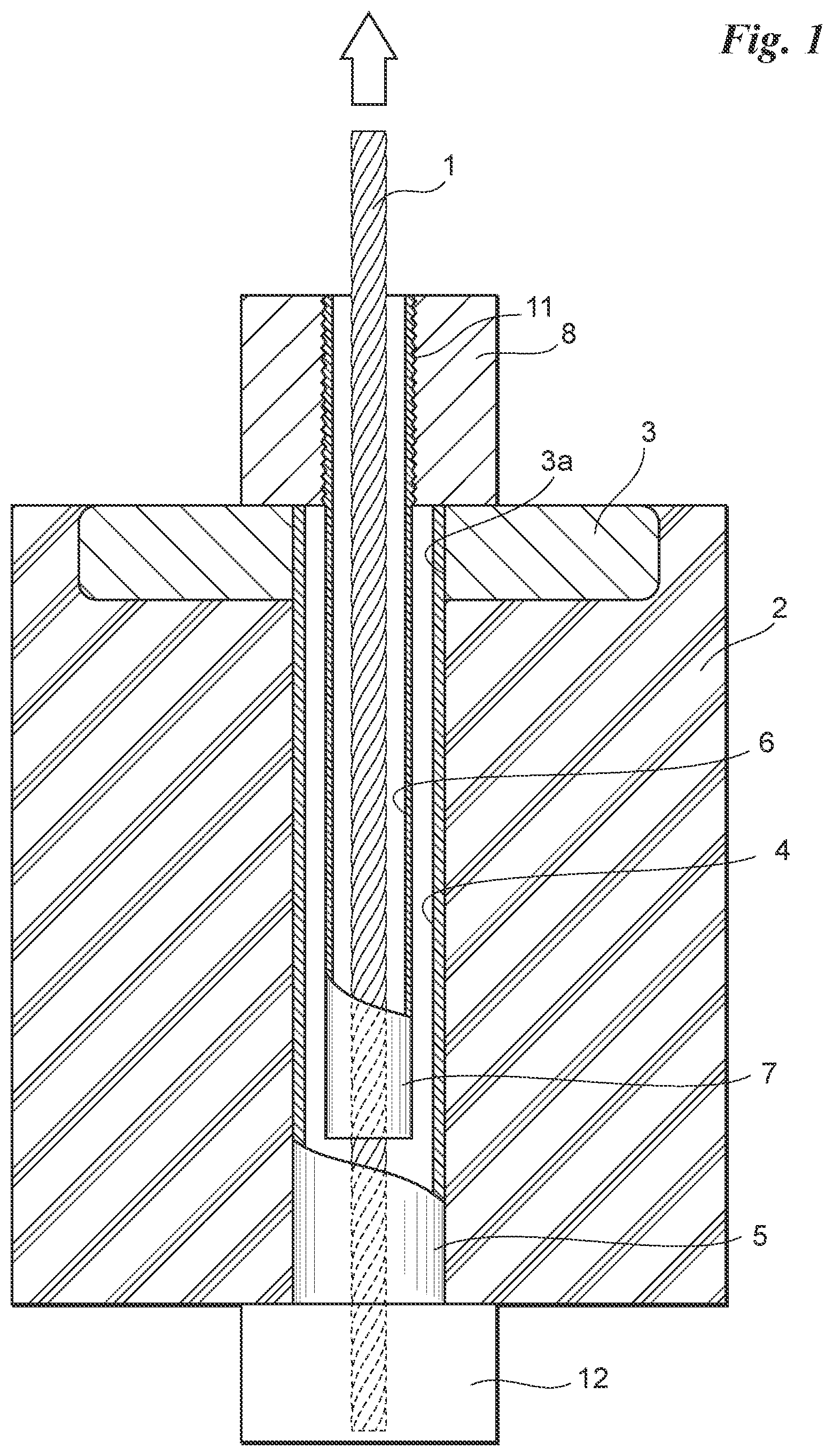
[0072] FIG. 1 is a cross-sectional view showing how pre-stress is introduced into a concrete structure using a post-tensioning system.
[0073] FIG. 2 is a cross-sectional view showing how pre-stress is introduced into a concrete structure using a post-tensioning system.
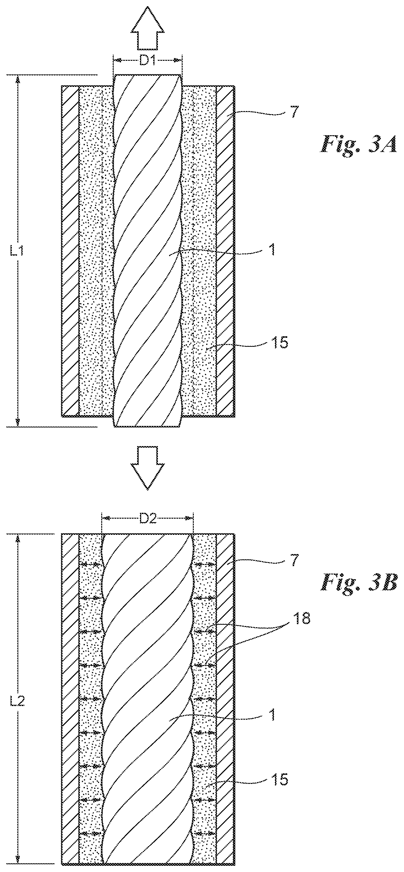
[0074] FIG. 3A is an enlarged cross-sectional view showing a tendon in a tensioned state together with a surrounding sleeve and PC grout filling the sleeve.
[0075] FIG. 3B is an enlarged cross-sectional view showing a tendon in a tension-released state together with the surrounding sleeve and the PC grout filling the sleeve.
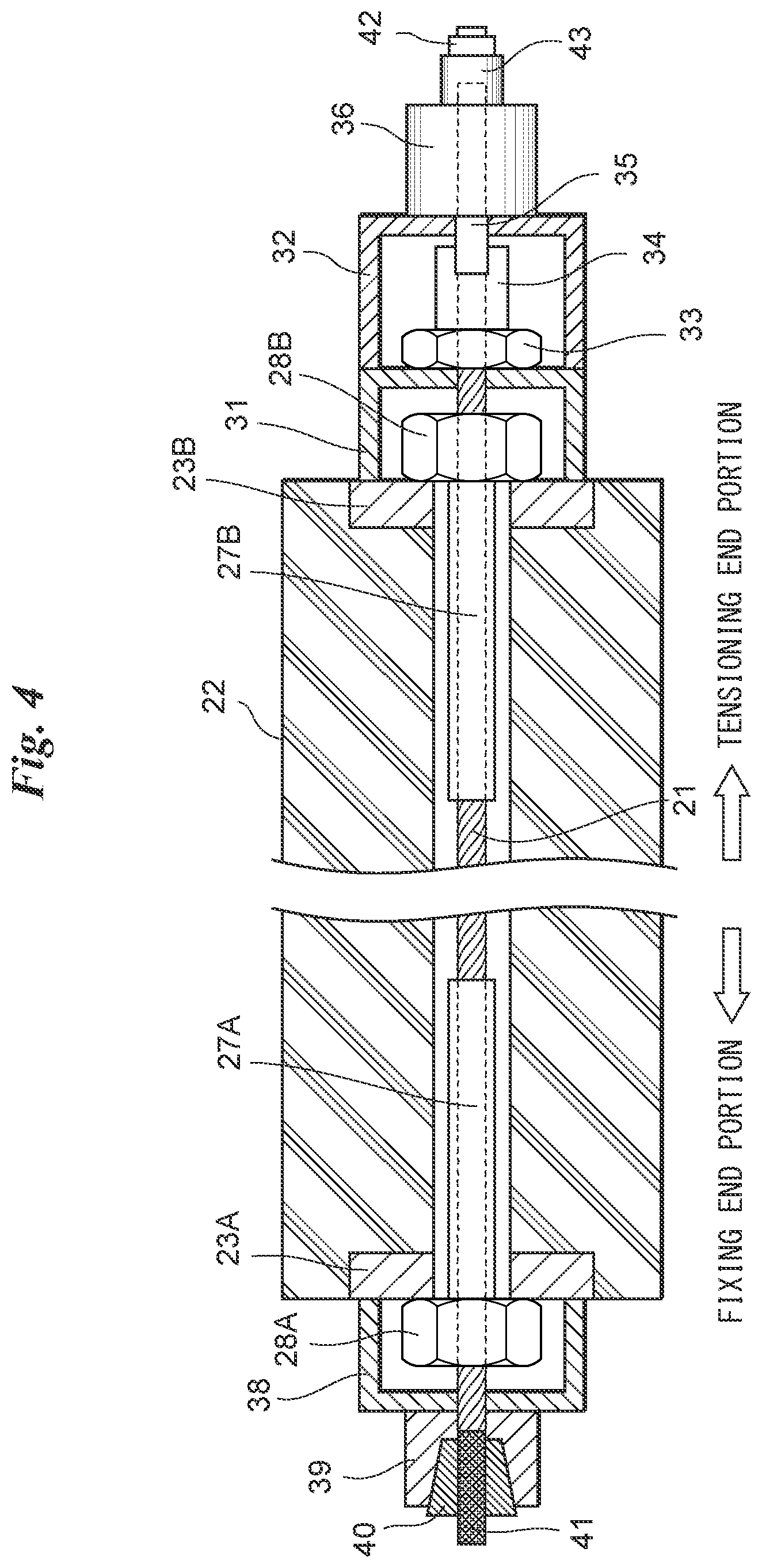
[0076] FIG. 4 is a cross-sectional view of a first example showing how pre-stress is introduced into a concrete structure using a post-tensioning system.
[0077] FIG. 5 is a cross-sectional view of a second example showing how pre-stress is introduced into a concrete foundation structure using a post-tensioning system.
[0078] FIG. 6 is a cross-sectional view of a third example showing how pre-stress is introduced into a PC composite bridge using a post-tensioning system.
[0079] FIG. 7 shows a process of manufacturing a pre-stressed concrete structure member using a pre-tensioning system.
[0080] FIG. 8 shows a process of manufacturing a pre-stressed concrete structure member using a pre-tensioning system.
[0081] FIG. 9 shows a process of manufacturing a pre-stressed concrete structure member using a pre-tensioning system.
[0082] FIG. 10 is a partially enlarged plan view showing an enlarged version of one end portion of the concrete structure member shown in FIG. 8.
DESCRIPTION OF THE PREFERRED EMBODIMENTS
[0083] FIGS. 1 and 2 are cross-sectional views showing how pre-stress is introduced into a concrete structure using a post-tensioning system. A concrete structure introduced with pre-stress is called pre-stressed concrete structure. FIG. 3A is an enlarged schematic cross-sectional view showing a tendon (a stressing member, a tensioning member) in a tensioned state to be described below together with a surrounding sleeve and PC grout filling the sleeve. FIG. 3B is an enlarged schematic cross-sectional view showing a tendon in a tension-released state together with the surrounding sleeve and the PC grout filling the sleeve as well as compression stress (double-headed arrows) occurring in the PC grout.
[0084] As will be described in more detail below, the tendon is provided within the concrete structure to introduce pre-stress into the concrete structure. When one end (fixing end) of the tendon is fixed and the other end (tensioning end) is pulled outward, the tendon is applied with longitudinal tension. A fixing device for fixing one end of the tendon is shown schematically in FIGS. 1 and 2. A tensioning device for pulling the other end of the tendon is not shown in FIGS. 1 and 2. Specific examples of the fixing device and the tensioning device will hereinafter be described.
[0085] Referring to FIG. 1, a metal or polyethylene cylindrical sheath tube 5 is embedded in the concrete structure 2. The hollow space of the sheath tube 5 is used as an insertion hole 4 through which a sleeve 7 to be described below is inserted. The sheath tube 5 may employ, for example, a spiral sheath with its inner and outer peripheral surfaces made concavo-convex.
[0086] A metal bearing plate 3 is provided on the upper surface of the concrete structure 2. The bearing plate 3 is formed with a cylindrical through hole 3a having a diameter approximately equal to the outer diameter of the sheath tube 5 provided in the concrete structure 2, and the sheath tube 5 is also inserted through the through hole 3a of the bearing plate 3. The insertion hole 4 (hollow space of the sheath tube 5) is opened outward at the upper end face of the bearing plate 3. The through hole 3a of the bearing plate 3 may be formed to have a diameter slightly greater than the outer diameter of the sheath tube 5.
[0087] A metal cylindrical rigid sleeve 7 is inserted through the insertion hole 4. The sleeve 7 has an outer diameter smaller than the insertion hole 4 (inner diameter of the sheath tube 5). An annular clearance gap is formed between the sheath tube 5 and the sleeve 7 in a cross-sectional view. The inner and outer peripheral surfaces of the sleeve 7 may also be made concavo-convex (e.g., threaded). Both the inner and outer peripheral surfaces of the sleeve 7 are preferably made concavo-convex, though may be either the inner or outer peripheral surface of the sleeve 7. For the sleeve 7, a metal member having a rigidity in the circumferential direction tolerable the compressive stress 18 occurred in a PC grout 15 described later can be used. The rigidity of the sleeve 7 can be adjusted by the rigidity of the adopted metal member itself and the wall thickness thereof.
[0088] An upper end portion of the sleeve 7 extends above the bearing plate 3 and a screw thread 11 is formed on the outer peripheral surface of the upper end portion of the sleeve 7 extending above the bearing plate 3. A locknut 8 with a screw thread formed on the inner peripheral surface thereof is threadably mounted on the upper end portion of the sleeve 7 with the screw thread 11 formed on the outer peripheral surface thereof and engaged tightly with the outer peripheral surface of the sleeve 7 in contact with the upper surface of the bearing plate 3.
[0089] The tendon 1, which has a diameter smaller than the inner diameter of the sleeve 7, is inserted through the hollow space 6 of the sleeve 7 extending from the locknut 8 through the bearing plate 3 into the concrete structure 2. An annular clearance gap is also formed between the tendon 1 and the inner peripheral surface of the sleeve 7 in a cross-sectional view.
[0090] The tendon 1 can employ a continuous fiber-reinforced polymer strand composed of one core strand and multiple (e.g., six) side strands twisted around the core strand. The tendon 1 and the core strand and the side strands forming the tendon 1 each have an approximately circular shape in a cross-sectional view (not shown). Also, the core strand is arranged at the center of the tendon 1 and the multiple side strands are positioned to surround the core strand in a cross-sectional view. The tendon 1 has a diameter of about 5 mm to 40 mm, for example.
[0091] The core strand and the side strands constituting the tendon 1 each form a resin containing fiber bundle obtained by bundling, into a cross-sectionally circular shape, multiple (e.g., several tens of thousands of) elongated continuous carbon fibers impregnated with thermosetting resin or thermoplastic resin for curing. Each of the carbon fibers is very thin, having a diameter of 5 .mu.m to 7 .mu.m, for example. The tendon 1 may be said to be made of Carbon Fiber Reinforced Plastics. Aramid fiber or glass fiber may be used in lieu of carbon fiber. Epoxy resin or vinyl ester resin, for example, is used as the thermosetting resin. Polycarbonate or polyvinyl chloride, for example, is used as the thermoplastic resin.
[0092] One end (lower end in FIG. 1; fixing end) of the tendon 1 extending downward from the lower surface of the concrete structure 2 is fixed by a fixing device 12. The other end (upper end in FIG. 1; tensioning end) of the tendon 1 extending upward from the locknut 8 is pulled (also referred to as "applied with tension") upward by a tensioning device (not shown). Since the one end (fixing end) of the tendon 1 is fixed, when the other end (tensioning end) of the tendon 1 is pulled, a longitudinal tensile force (also referred to as tensioning force) is applied to the tendon 1 and stress corresponding thereto occurs within the tendon 1. The tendon 1 stretches in proportion to the stress and cross-sectional contraction occurs (the diameter of the tendon 1 contracts). In FIG. 3A, the tendon 1 (its thickness) before being pulled in the longitudinal direction is indicated by broken lines.
[0093] As shown in FIGS. 2 and 3A, PC grout 15 fills the sleeve 7 with the tendon 1 kept in a tensioned state. Referring to FIG. 2, the PC grout 15 fills not only the sleeve 7 but also the sheath tube 5.
[0094] Referring to FIGS. 2 and 3B, after the PC grout 15 is cured and a predetermined strength is expressed, the tension within the tendon 1 by the tensioning device is released. The tendon 1, when applied with tension by the tensioning device, stretches in the longitudinal direction (axial direction) and thereby tensile strain occurs in the longitudinal direction. When the tension within the tendon 1 is released, a Poisson effect occurs in the tendon 1 and expansive strain by the Poisson's ratio occurs circumferentially outward of the tendon 1 (in the direction perpendicular to the axis), whereby the tendon 1 expands circumferentially outward. That is, comparing FIGS. 3A and 3B, when the tension within the tendon 1 is released, the tendon 1 contracts in the longitudinal direction (L1>L2), while expands in the radial direction (D1<D2). It is noted that how the tendon 1 contracts and expands is drawn with considerable emphasis in FIGS. 3A and 3B. As a result, as schematically shown in FIG. 3B, predetermined compression stress 18 occurs in the PC grout 15 filling the clearance gap between the tendon 1 and the sleeve 7. This compression stress 18 causes the tendon 1 to be anchored reliably to the sleeve 7. In addition, since the tension within the tendon 1 is released and the tendon 1 contracts in the longitudinal direction, the locknut 8 threadably coupled to the upper end portion of the sleeve 7 is urged against the bearing plate 3 (tensioning reaction force) and pre-stress occurs in the concrete structure 2. The tendon 1 is thus anchored reliably within the concrete structure 2 and the structural performance of the concrete structure 2 is improved with the pre-stress introduced.
[0095] Specific examples of a concrete structure introduced with pre-stress will hereinafter be described with reference to FIGS. 4 to 10.
FIRST EXAMPLE
[0096] FIG. 4 shows a first example, illustrating in detail examples of a fixing device and a tensioning device for applying tension to a tendon. FIG. 4 does not show a sheath tube that is provided to allow an insertion hole within the concrete structure.
[0097] Referring to the left part in FIG. 4, the fixing device includes a bearing plate 23A provided at one end (left end in FIG. 4) of the concrete structure 22, a locknut 28A, a ram chair 38, an anchor head 39, a friction sheet and blade net 41, and a wedge 40. A sleeve 27A is inserted through a sheath tube (insertion hole) that is embedded in the concrete structure 22, and a tendon 21 is inserted through the sleeve 27A. The sleeve 27A is inserted through the through hole of the bearing plate 23A, and a leading end portion thereof is put on the outside of the bearing plate 23A. The locknut 28A is threadably mounted on the leading end portion of the sleeve 27A that is put on the outside of the bearing plate 23A.
[0098] The ram chair 38 is installed on the bearing plate 23A in a manner surrounding the locknut 28A. The ram chair 38 has an insertion hole at its center through which the tendon 21 is inserted, and a leading end portion (fixing end) of the tendon 21 is inserted through the insertion hole of the ram chair 38 and put on the outside of the ram chair 38.
[0099] The anchor head 39 is installed on the ram chair 38. The anchor head 39 has an insertion hole through which the leading end portion of the tendon 21 is inserted and a hollow space tapered for wedge into which the wedge 40 is pushed. The leading end portion of the tendon 21 that is put on the outside of the ram chair 38 is inserted through the insertion hole and the hollow space of the anchor head 39 to extend out of the anchor head 39. The friction sheet and blade net 41 is wound around the leading end portion of the tendon 21 that is put on the outside of the anchor head 39 and the exterior thereof is covered with the wedge 40, and the leading end portion of the tendon 21 covered with the wedge 40 is pushed into the hollow space of the anchor head 39. The leading end portion of the tendon 21 is anchored reliably within the hollow space tapered for wedge of the anchor head 39.
[0100] The friction sheet and blade net 41 is put on the outer peripheral surface of the leading end portion of the tendon 21 covered with the wedge 40 to reduce the clamping force of the wedge 40 against the tendon 21.
[0101] Referring to the right part in FIG. 4, the tensioning device includes a bearing plate 23B provided at the other end (right end in FIG. 4) of the concrete structure 22, a locknut 28B, ram chairs 31, 32, a ring nut 33, an expansion material filling sleeve 34, a tension bar 35, a center hole tensioning jack 36, a wedge 42, and an anchor head 43.
[0102] A sleeve 27B is inserted through an insertion hole of the concrete structure 22, and a tendon 21 is inserted through the sleeve 27B. The sleeve 27B is inserted through the through hole of the bearing plate 23B and put on the outside of the bearing plate 23B. The locknut 28B is threadably mounted on the leading end portion of the sleeve 27B that is put on the outside of the bearing plate 23B.
[0103] The first ram chair 31 is installed on the bearing plate 23B in a manner surrounding the locknut 28B. The first ram chair 31 has an insertion hole at its center through which the tendon 21 is inserted, and a leading end portion (tensioning end) of the tendon 21 is inserted through the insertion hole of the first ram chair 31 and put on the outside of the first ram chair 31.
[0104] The expansion material filling sleeve 34 is fabricated in a factory and provided on the leading end portion of the tendon 21 that is put on the outside of the first ram chair 31. Expansion material fills the expansion material filling sleeve 34 and provides expansion pressure of the expansion material to anchor the expansion material filling sleeve 34 reliably to the leading end portion of the tendon 21. The outer peripheral surface of the expansion material filling sleeve 34 is threaded, through which the ring nut 33 is fixed to the expansion material filling sleeve 34.
[0105] The second ram chair 32 is overlaid on the first ram chair 31 in a manner surrounding the ring nut 33 and the expansion material filling sleeve 34. The second ram chair 32 also has an insertion hole at its center through which the tendon 21 is inserted, and a leading end portion (tensioning end) of the tendon 21 is inserted through the insertion hole of the second ram chair 32 and put on the outside of the second ram chair 32.
[0106] The center hole tensioning jack 36 is installed on the second ram chair 32. After the installation of the center hole tensioning jack 36, the tension bar 35 is engaged with the inner thread of the expansion material filling sleeve 34. The leading end portion of the tendon 21 passes through the center hole tensioning jack 36 to be anchored to the leading end of the ram of the center hole tensioning jack 36 using the wedge 42 and the anchor head 43. When the center hole tensioning jack 36 is actuated and the tendon 21 is applied with tension, the center hole tensioning jack 36 moves away from the second ram chair 32. Since the center hole tensioning jack 36 is connected with the above-described expansion material filling sleeve 34 by the tension bar 35, the expansion material filling sleeve 34 also moves away from the first ram chair 31 by the tension bar 35. When a predetermined tensioning force is applied to the tendon 21, the ring nut 33 that is placed on the outer peripheral surface of the expansion material filling sleeve 34 is fastened and thereby fixed and anchored to the first ram chair 31. When the ring nut 33 is fastened, the tensioning force is maintained at the tensioning end by the first ram chair 31, the expansion material filling sleeve 34, and the ring nut 33. Thereafter, the center hole tensioning jack 36 is de-actuated, the center hole tensioning jack 36, the tension bar 35, and the second ram chair 32 can be uninstalled. The center hole tensioning jack 36, the tension bar 35, and the second ram chair 32, after uninstalled, can be used to apply tension to a tendon 21 at another location.
[0107] PC grout fills the insertion hole (sheath tube) of the concrete structure 22 with the tendon 21 kept in a tensioned state. The PC grout also fills the sleeves 27A, 27B. Before filling with the PC grout, seal may be applied around the bearing plates 23A, 23B so that the PC grout cannot leak out of the bearing plates 23A, 23B. After the PC grout is cured and a predetermined strength occurs, the tendon 21 is cut off in the vicinity of the locknut 28A, 28B and thereby the tension is released. As described above, when the tensioning force is released, predetermined compression stress occurs in the PC grout filling the clearance gap between the tendon 21 and the sleeves 27A, 27B, and the compression stress causes the tendon 21 to be anchored reliably to the sleeves 27A, 27B. In addition, tensioning stress is introduced into the concrete structure 22 via the bearing plates 23A, 23B.
SECOND EXAMPLE
[0108] FIG. 5 is a cross-sectional view showing how pre-stress is introduced into a concrete foundation structure using a post-tensioning system. Also in FIG. 5, a sheath tube is not shown. This presents an anchoring construction method that is hard to achieve with a related-art method and can specifically be utilized, for example, as a construction method for efficiently and reasonably anchoring a steel tower portion of a power transmission tower foundation to a concrete foundation.
[0109] FIG. 5 is a vertical cross-sectional view of a portion of a columnar or rectangular concrete foundation structure 52. The concrete foundation structure 52 shown in FIG. 5 is embedded in the ground and has an elongated shape in the depth (vertical) direction.
[0110] The concrete foundation structure 52 shown in FIG. 5 is a pre-stressed concrete foundation structure in which pre-stress is introduced in the vertical direction. Power transmission tower foundations have conventionally and frequently employed rebar-reinforced concrete structures. However, a pre-stressed concrete structure may be employed with the view to an improvement in the performance and/or functionality.
[0111] The foundation base plate 55 of the concrete foundation structure 52 shown in FIG. 5 corresponds to the above-described bearing plate, not including separate bearing plates provided correspondingly for the respective tendons but including a single thickened bearing plate used in common with the multiple tendons. The foundation base plate 55 plays another role. That is, a power transmission tower foundation truss (a columnar pipe or an angle bar, for example, is used) is welded onto the foundation base plate 55 via a reinforcement plate such as a shear plate (not shown). Since the power transmission tower is applied with a group of loads including its own dead load, wind load, earthquake load, etc. that acts on the wires and/or the tower, it is necessary to transmit such an external force to the concrete foundation structure built in the ground to thereby maintain the stability of the foundation with a reaction force from the ground. That is, a strong cross-sectional force such as a horizontal shear force, a pull-out force, and a bending moment acts on the foundation base plate that is installed on the concrete foundation through the tower foundation truss.
[0112] As a method for anchoring a steel truss tower to a concrete foundation, there has conventionally been employed a construction type in which an anchor-shaped steel truss reinforced with a shear plate at the leading end of the steel truss tower is embedded directly into a cast-in-place concrete foundation and reinforced therearound with reinforcing steel bars to integrate the tower foundation truss and the concrete foundation.
[0113] In the related-art anchor foundation type, since the anchor portion is installed in an inclined manner into the concrete foundation, it is very difficult to ensure accuracy for the installation. It is particularly necessary to install the steel truss tower not vertically but in an inclined manner and further at an installation accuracy of as high as 3 to 5 mm. This suffers from some problems that a specialized installation technique that only a limited number of construction vendors can support is required and that it results in an increase in the installation cost.
[0114] The foundation base plate 55 shown in FIG. 5 has a structure installed horizontally and directly on the upper surface of the concrete foundation structure 52 and directly utilizing tensioning forces within the tendons 51 to resist various active loads from the upper part of the power transmission tower. The power transmission tower truss is fabricated in a manner inclined with respect to the foundation base plate 55. A tensile force, a shear force, and a bending moment then act on the foundation base plate 55 as a major cross-sectional force.
[0115] A working procedure for introducing pre-stress into the concrete foundation structure 52 shown in FIG. 5 will be described in sequence and also the synergy with the present invention.
[0116] The fixing end portion of each of the tendons 51 will first be described. In the concrete foundation 52 shown in FIG. 5, the fixing end of the tendon 51 is not fixed by a fixing device. That is, the insertion hole (sheath tube) through which the tendon 51 is inserted is not formed entirely from one end (upper end) to the other end (bottom end) of the concrete foundation 52, but formed to a middle portion of the concrete foundation 52. This is for the reason that since the bottom surface of the concrete foundation 52 shown in FIG. 5 is in contact with the supporting ground, even if the sheath tube may be inserted to the bottom surface of the concrete foundation 52, there is no space or working space to anchor the tendon 51 to the concrete foundation 52 using a fixing device.
[0117] There has been an untwisting-type anchorage (Japanese Patent No. 6442104) practiced as a structure for anchoring one end (fixing end) of a tendon 51 within a sheath tube (insertion hole) provided in a concrete foundation 52. The untwisting-type anchorage 53 is obtained by untwisting the twisted side strands (loosening the twisted side strands) that form the tendon 51 along a predetermined length and filling the clearance gap (space) formed thereby with resin mortar or cement mortar. The tendon 51 is inserted through the untwisting-type anchorage 53 formed at one end into the sheath tube provided in the concrete foundation structure 52. Before tensioning of the tendon 51, PC grout 56 fills the space around the untwisting-type anchorage 53 to thereafter be cured. With strength expression in the PC grout 56, the one end portion (fixing end) of the tendon 51 is anchored (fixed) reliably to the concrete foundation 52.
[0118] Before the tendon 51 is inserted into the sheath tube, the foundation base plate 55 is installed. The foundation base plate 55 plays a role as a bearing plate as well as of fixing the tower foundation truss to transmit a cross-sectional force acting on the tower foundation truss to the concrete foundation. That is, a shear force and a pull-out force act on the foundation base plate 55.
[0119] The tendon 51 is applied with upward tension using a tensioning device described with reference to FIG. 4. After tensioning operations for all the tendons 51, PC grout (not shown) fills the sheath tubes and the sleeves 57 to thereafter be cured. After strength expression in the PC grout, the tensioning forces are released. As mentioned above, since the sleeves 57 are anchored reliably to the tendons 51, the tensioning forces are transmitted through the locknuts 58 engaged with the sleeves 57 to the foundation base plate 55, whereby the foundation base plate 55 is urged against the upper surface of the concrete foundation 52 and thus pre-stress is introduced into the entire concrete foundation 52. In addition, predetermined compression stress occurs in the PC grout filling the clearance gap between the tendons 51 and the sleeves 57, and the compression stress causes the tendons 51 to be anchored reliably to the sleeves 57.
[0120] The present invention being applied, the concrete foundation 52 shown in FIG. 5 can show a more critical synergy. As mentioned above, a shear force and a pull-out force act on the foundation base plate 55. First, if the acting drawing force is weaker than the sum of the tensioning forces, the foundation base plate 55 cannot be deformed upward according to the principle of pre-stress. It is therefore only required to set a design tensioning force greater than the maximum pull-out force.
[0121] Next is a resistance mechanism of the foundation base plate 55 by a shear force. Since compression stress due to the tensioning forces acts between the foundation base plate 55 and the upper surface of the concrete foundation 52, the product of the compression stress and the friction coefficient therebetween serves as a shear resistance. Further, in a method for increase in the shear resistance, convex portions such as, for example, round steels protrude from the lower surface of the foundation base plate 55 as shear keys 59, while recessed portions are provided in the upper surface of the receiving concrete foundation 52, such that the convex portions and the recessed portions are engaged with each other. This allows the sum of (the cross-sectional area of each convex portion).times.(the shear resistance stress of each convex portion) to be considered as shear resistance (design resistance).
[0122] It is noted that before installation of the foundation base plate 55, filler/curing agent such as epoxy resin or grout mortar may be put in the recessed portions so that the convex portions and the recessed portions are in constant contact with each other.
THIRD EXAMPLE
[0123] FIG. 6 shows a case where an example according to the present invention is applied a PC composite bridge. The PC composite bridge is a pre-stressed concrete bridge constructed by fabricating a main girder portion and a floor slab portion forming the pre-stressed concrete bridge separately on site or in a PC factory and, in a working field, first installing the main girder portion and thereon the floor slab portion and then joining the main girder portion and the floor slab portion.
[0124] Referring to FIG. 6, the PC composite bridge shown in FIG. 6 includes an I-shaped main girder portion 63 and a floor slab portion 66 fixed on the upper surface of the main girder portion 63. It is noted that the main girder portion 63 may have not only an I shape but also a U shape, to both of which the technique according to the present invention is applicable. A tendon can be used for (1) joint between the main girder portion 63 and the floor slab portion 66, (2) shear reinforcement by vertical tensioning of the main girder portion 63, and (3) a shear reinforcement bar of the main girder portion 63.
[0125] The main girder portion 63 includes a web 63A extending straight-forward vertically, a head portion 63B formed integrally with the upper surface of the web 63A, and a leg portion 63C formed integrally with the lower surface of the web 63A. A sheath tube (not shown) is provided in the web 63A and the head portion 63B, and a vertically extending insertion hole is ensured by the sheath tube. On the other hand, the sheath tube (insertion hole) is provided to a middle portion of the leg portion 63C.
[0126] A box-shaped portion (recessed portion) 60 is formed in the upper surface of the floor slab portion 66, and a bearing plate 69 with a through hole opened therein is installed on the bottom surface of the box-shaped portion 60. The sheath tube is inserted from the bearing plate 69 to the lower surface of the floor slab portion 66 to ensure an insertion hole.
[0127] After multiple main girder portions 63 are provided with spacing therebetween, a vent (temporary bridge pier) (not shown) is provided between adjacent ones of the main girder portions 63. After the multiple main girder portions 63 and the multiple vents are joined and applied with tension in the bridge axial direction, the floor slab portions 66 are installed. Upon installation of the floor slab portion 66, sealing materials 64A are provided on either side of the upper surface of the main girder portion 63 and non-shrink mortar 64B is placed between the sealing materials 64A, onto which the floor slab portion 66 is installed (wet-joint construction method). A tendon 61 with a sleeve 67 and a locknut 68 provided in one end portion thereof and a factory-processed untwisting-type anchorage 62 provided at the other end thereof is inserted through the box-shaped portion 60 of the floor slab portion 66 into the sheath tube of the main girder portion 63. The untwisting-type anchorage 62 at the other end of the tendon 61 reaches the leg portion 63C of the main girder portion 63. Before tensioning of the tendon 61, PC grout 65 fills the space around the untwisting-type anchorage 62. With strength expression in the PC grout 65, the other end portion (fixing end) of the tendon 61 is fixed reliably to the main girder portion 63, as described with reference to FIG. 5. Thereafter, with the same construction method as that described with reference to FIG. 5, the tendon 61 is applied with upward tension using a tensioning device. With the tendon 61 in a tensioned state, PC grout fills the sheath tube and the sleeve 67 to thereafter be cured. After strength expression in the PC grout, the tension within the tendon 61 is released. Predetermined compression stress occurs in the PC grout filling the clearance gap between the tendon 61 and the sleeve 67, and the compression stress causes the tendon 61 to be anchored reliably to the sleeve 67. In addition, tensioning load is transmitted to the locknut 68 and the bearing plate 69, whereby pre-stress is introduced into the floor slab portion 66 and the main girder portion 63.
[0128] In this third example, synergies with the present invention are as follows.
(1) First Synergy
[0129] In this third example, pre-stress is required to be distributed in the wet-joint portions 64A, 64B between the floor slab portion 66 and the upper end portion of the main girder portion 63. In the present invention, since the bearing plate 69 has an effect of distributing a tensioning force, required pre-stress can be looked for in the wet-joint portions 64A, 64B. In addition, since the bearing plate 69 can achieve a significantly small-sized structure compared to related-art tensioning end portions, anchoring jigs can be accommodated within the floor slab portion 66.
(2) Second Synergy
[0130] The tendon 61 within the main girder portion 63 contributes to the joint between the main girder portion 63 and the floor slab portion 66. Further, the tendon 61 is arranged vertically along the web 63A, with the ends thereof being anchored to the concrete (the floor slab portion 66 and the main girder portion 63), to effectively serve as a shear reinforcement bar. In general, shear reinforcement bars are disadvantageous in that a bending hook or the like is required for concrete anchoring to result in a need for additional processing cost and/or extra length for anchoring, that is, additional material cost. In this third example, shear reinforcement can be provided only with the straight portion of the tendon 61, leading to cost reduction.
(3) Third Synergy
[0131] There are three methods for shear reinforcement of the main girder portion 63: (i) arranging a shear reinforcement bar, (ii) applying tension to the main girder portion 63 in the bridge axial direction, and (iii) applying vertical tension to the main girder portion 63. Among these methods, (i) method of arranging a shear reinforcement bar is most frequently employed due to its working easiness and the like. (ii) Method of applying tension in the bridge axial direction is the second most-employed one. In a pre-stressed concrete bridge, tension is naturally applied in the bridge axial direction and thereby a shear reinforcement effect can necessarily be expected. (iii) Shear reinforcement method of applying vertical tension to the web 63A is hardly employed for the reason that it has working difficulty. However, in this third example, the vertical tensioning effect that is applied to the joint between the main girder portion 63 and the floor slab portion 66 can be taken into design consideration as a shear reinforcement effect of the main girder portion 63. The vertical tensioning effect can significantly increase load capacity against shear force and/or occurrence of oblique crack as well as reduce the width of oblique crack.
FOURTH EXAMPLE
[0132] FIGS. 7 to 10 show processes of manufacturing a pre-stressed concrete structure member using a pre-tensioning system. FIGS. 7 to 9 show layouts in a side view of a PC production line in a PC factory for manufacturing a pre-stressed concrete structure member. FIG. 10 is a partially broken plan view showing an enlarged version of one end portion of the concrete structure member shown in FIG. 8.
[0133] In a general PC production line using a pre-tensioning system, an abutment for taking a reaction force of a tensioning force is provided and the tensioning force undergo fixing anchoring and tension anchoring, respectively, on the fixing side and the tensioning side to manufacture a PC concrete member using a pre-tensioning system. The fixing anchoring and the tension anchoring are here conventionally implemented and will not be described herein.
[0134] In a general pre-tensioning system, such a locknut-and-bearing-plate 75 and a sleeve 73 as shown in FIGS. 7 to 9 do not be provided in a member end portion. Accordingly, upon releasing a tensioning force in a member end portion, out-of-adhesion may occur between the tendon 71 and the concrete to result in that (i) if the tendon 71 is a PC steel strand (the diameter of the PC steel strand is represented by .phi.), it is impossible to expect pre-stress introduction from the end portion to the point of 65.phi. and (ii) if the tendon 71 is a continuous fiber-reinforced polymer strand (the diameter of the continuous fiber-reinforced polymer strand is represented by .phi.), it is difficult to expect pre-stress introduction from the end portion to the point of 50.phi..
[0135] The example of manufacturing a pre-stressed concrete structure member using a pre-tensioning system shown in FIGS. 7 to 9 is directed to the case where the member has a relatively small length. This is for the reason that since as described above, presetting the locknut-and-bearing-plate 75 and the sleeve 73 according to the present invention allows pre-stress to occur in the member end portion, effective pre-stress can be expected over the entire length of the member even if the member may be relatively short.
[0136] A working method according of a fourth example will be described. Basically, multiple (three in FIGS. 7 to 9) formworks 70 are arranged in line with spacing therebetween on a base, and a set of locknut-and-bearing-plate 75 and sleeve 73 engaged therewith is arranged in a manner contacting closely to each of the lateral end portions within each formwork 70. The tendon 71 is inserted so as to penetrate all the three formworks 70. The tendon 71 is inserted through the hollow spaces of all the sleeves 73 and the through holes of all the locknut-and-bearing-plates 75 that are arranged in lateral end portions within the formworks 70. It goes without saying that holes through which the tendon is inserted are opened in lateral end portions within the formworks 70. It is noted that the sleeve 73 is formed with a PC grout filling port and an air discharge port as will be described below.
[0137] Referring to FIG. 7, a tensioning abutment 76 and a tensioning jack 78 are provided at one end (tensioning end) (right part in FIG. 7) of the tendon 71 put on the outside of one of the three formworks 70 located at one end (right end in FIG. 7). Also, a fixing abutment 77 and a fixing device 79 are provided at the other end (fixing end) (left part in FIG. 7) of the tendon 71 put on the outside of one of the three formworks 70 located at the other end (left end in FIG. 7). With the other end being fixed by the fixing device 79, when the one end of the tendon 71 is pulled by the tensioning jack 78, a predetermined tensioning force is introduced into the tendon 71.
[0138] Referring to FIG. 10, a PC grout filling port 73a and an air discharge port 73b are opened in the sleeve 73. PC grout (not shown) fills the sleeve 73 through the PC grout filling port 73a and air within the sleeve 73 is discharged through the air discharge port 73b. This causes the PC grout to fill the clearance gap between the sleeve 73 and the tendon 71 inserted through the sleeve 73.
[0139] Referring to FIG. 8, after the PC grout filling the sleeve 73, concrete 72 is placed within the formworks 70. The PC grout and the concrete 72 are cured until expression of a predetermined strength.
[0140] Referring to FIG. 9, after the PC grout and the concrete 72 reaching a predetermined strength, the tendon 71 is released on either outside of each formwork 70. The tensioning force within the tendon 71 is loosened (released) and pre-stress is introduced into the concrete 72 within each formwork 70. In addition, predetermined compression stress occurs in the PC grout filling the clearance gap between the tendons 71 and the sleeves 73, and the compression stress causes the tendons 71 to be anchored reliably to the sleeves 73. Thereafter, when the formworks 70 are removed, a concrete structure (pre-tensioned member) into which pre-stress is introduced using a pre-tensioning system is completed.
[0141] With the foregoing series of operations, even a short member can be introduced efficiently with tensioning stress equally through the end portions thereof. In fabrication of a general pre-tensioned member, since there is a risk for the occurrence of fracturing cracks in a member end portion, the tendon is unbonded by a length of 20 to 30.phi. in the member end portion. Comparatively, in this case, since the locknut-and-bearing-plates 75 are provided in the end portions, such a risk cannot occur.
Comparison with Existing Techniques (1) Post-tensioning System with Bearing Plate and Expansion Material Sleeve
[0142] Existing techniques suffer from three problems as described above under the foregoing condition.
(i) Limitation on Tensioning of Lengthy Structure
[0143] To address this problem, in the present invention, the expansion material sleeve used for tensioning, which is eventually removed from the tensioning end portion of the structure, has an increased length and/or multiple expansion material sleeves are provided, and tensioning load by the tensioning jack is changed to get rid of the limitation on the length of the tendon. That is, in the present invention, since anchoring the tendon of the continuous fiber-reinforced polymer strand is eventually completed with the sleeve and the locknut engaged with the sleeve, upon completion, only the locknut of the anchoring portion can protrude from the tensioning end portion as shown in FIG. 1 or the anchoring portion cannot protrude at all as shown in FIG. 6.
(ii) Protrusion of Tensioning End Portion
[0144] In the present invention, the anchorage of the tensioning end portion and/or the fixing end portion can basically fulfill their functions within the concrete structure as shown in FIG. 1. In addition, the locknut can be thinned through creative design. As shown in FIG. 6, a box-shaped portion may be provided so that a component is accommodated within the concrete not to protrude at the end portion.
(iii) Adjustment of Tendon Length
[0145] On working site, the length of a tensioning target is sometimes required to be changed for various reasons. There are two coping methods according to the present invention.
Method A
[0146] The expansion material sleeve is fabricated to have an increased length. Since the ram chair shown in FIG. 4 can be divided into several pieces, the length of the ram chair is adjusted as appropriate, so that the factory-fabricated expansion material sleeve can be utilized adequately.
Method B
[0147] No factory-fabricated expansion material sleeve is used. The tendon of the continuous fiber-reinforced polymer strand, when carried into the site, is cut into a necessary length on site. The method of anchoring of the fixing end portion and the tensioning end portion basically employs the system including a friction sheet, a blade net, and a wedge as shown in FIG. 4. This method allows the anchoring position to be determined according to the on-site working conditions, which makes it possible to respond to a change in the length of the tendon. Even in such a case, applying the present invention allows the tension anchoring position to be set arbitrarily at the working end face, providing no working limitation.
(2) Pre-Tensioning System
[0148] Problems concerning the pre-tensioning system are as described above. To address these problems, in the present invention, even a short member can be introduced with predetermined pre-stress between the end portions as described above. It is also possible to eliminate a risk of splitting crack occurrence in a member end portion, which has been a working risk in the case of a related-art pre-tensioning system.
* * * * *
D00000
D00001
D00002
D00003
D00004
D00005
D00006
D00007
D00008
D00009
D00010
XML
uspto.report is an independent third-party trademark research tool that is not affiliated, endorsed, or sponsored by the United States Patent and Trademark Office (USPTO) or any other governmental organization. The information provided by uspto.report is based on publicly available data at the time of writing and is intended for informational purposes only.
While we strive to provide accurate and up-to-date information, we do not guarantee the accuracy, completeness, reliability, or suitability of the information displayed on this site. The use of this site is at your own risk. Any reliance you place on such information is therefore strictly at your own risk.
All official trademark data, including owner information, should be verified by visiting the official USPTO website at www.uspto.gov. This site is not intended to replace professional legal advice and should not be used as a substitute for consulting with a legal professional who is knowledgeable about trademark law.