Polishing Pad Conditioner And Manufacturing Method Thereof
Chou; Jui-Lin ; et al.
U.S. patent application number 17/363489 was filed with the patent office on 2022-04-14 for polishing pad conditioner and manufacturing method thereof. The applicant listed for this patent is KINIK COMPANY. Invention is credited to Chin-Chung Chou, Jui-Lin Chou, Chun-Kai Tang, Pin-Hsien Wang, Min-Hung Wu.
| Application Number | 20220111488 17/363489 |
| Document ID | / |
| Family ID | 1000005725728 |
| Filed Date | 2022-04-14 |


| United States Patent Application | 20220111488 |
| Kind Code | A1 |
| Chou; Jui-Lin ; et al. | April 14, 2022 |
POLISHING PAD CONDITIONER AND MANUFACTURING METHOD THEREOF
Abstract
The present invention relates to a polishing pad conditioner and a manufacturing method thereof. The polishing pad conditioner includes a substrate, an abrasive layer and a protective layer. The abrasive layer covers the surface of the substrate. The abrasive layer includes a bonding layer and a plurality of abrasive particles embedded in the bonding layer. Each of the abrasive particles has a protrusion exposed out of the bonding layer, and the protrusion is insulated. The protective layer covers the surface of the bonding layer, and the protrusion is exposed out of the protective layer. The polishing pad conditioner of the present invention can protect the bonding layer from being damaged by abrasion and hold the abrasive particles, avoid the abrasive particles from falling off or out of position, and maintain the polishing effect and service life of the polishing pad conditioner.
| Inventors: | Chou; Jui-Lin; (New Taipei City, TW) ; Wu; Min-Hung; (New Taipei City, TW) ; Chou; Chin-Chung; (New Taipei City, TW) ; Wang; Pin-Hsien; (New Taipei City, TW) ; Tang; Chun-Kai; (New Taipei City, TW) | ||||||||||
| Applicant: |
|
||||||||||
|---|---|---|---|---|---|---|---|---|---|---|---|
| Family ID: | 1000005725728 | ||||||||||
| Appl. No.: | 17/363489 | ||||||||||
| Filed: | June 30, 2021 |
| Current U.S. Class: | 1/1 |
| Current CPC Class: | B24B 37/245 20130101; B24B 37/22 20130101; B24D 3/004 20130101; B24B 53/001 20130101; B24B 53/017 20130101 |
| International Class: | B24B 53/017 20060101 B24B053/017; B24B 53/00 20060101 B24B053/00; B24B 37/24 20060101 B24B037/24; B24B 37/22 20060101 B24B037/22; B24D 3/00 20060101 B24D003/00 |
Foreign Application Data
| Date | Code | Application Number |
|---|---|---|
| Oct 14, 2020 | TW | 109135518 |
Claims
1. A polishing pad conditioner, comprising: a substrate; an abrasive layer covering a surface of the substrate, wherein the abrasive layer includes a bonding layer and a plurality of abrasive particles embedded in the bonding layer, each of the abrasive particles has a protrusion exposed out of the bonding layer, and the protrusion is insulated; and a protective layer covering a surface of the bonding layer, wherein the protrusion is exposed outside the protective layer.
2. The polishing pad conditioner of claim 1, wherein the protective layer is formed by an electrodeposition coating composition; wherein the electrodeposition coating composition includes a main resin, and the main resin is epoxy resin, acrylic resin, polybutadiene resin, polyester resin or polyamide resin.
3. The polishing pad conditioner of claim 1, wherein the substrate is a metal substrate, a metal alloy substrate, a stainless steel substrate, or a mold steel substrate.
4. The polishing pad conditioner of claim 1, wherein the bonding layer is made of brazing material, electroplating material, ceramic material, metal material or polymer material.
5. The polishing pad conditioner of claim 1, wherein the abrasive particles are at least one abrasive particles selected from a group consisting of natural diamond, synthetic diamond, polycrystalline diamond, cubic boron nitride, aluminum oxide, and silicon carbide.
6. The polishing pad conditioner of claim 1, which has a cutting rate (CR.sub.completed), wherein the variation rate between the cutting rate (CR.sub.completed) and the cutting rate (CR.sub.initial) of a polishing pad conditioner that is not covered with a protective layer is less than 10%.
7. A method for manufacturing a polishing pad conditioner, the steps of which include: (a) providing a substrate; (b) forming an abrasive layer on a surface of the substrate, wherein the abrasive layer includes a bonding layer and a plurality of abrasive particles embedded in the bonding layer, and each abrasive particle has a protrusion exposed above the bonding layer; (c) subjecting the protrusions to an insulation treatment; and (d) electrodepositing a protective layer on a surface of the bonding layer, and exposing the insulated protrusions outside the protective layer.
8. The method of claim 7, wherein the insulation treatment includes physical insulation or chemical insulation.
9. The method of claim 8, wherein the physical insulation includes sandblasting insulation or plasma insulation.
10. The method of claim 8, wherein the chemical insulation includes etching insulation.
11. The method of claim 10, wherein the etching insulation includes etching with a chemical solution, wherein the chemical solution includes at least one selected from a group consisting of nitric acid, aqua regia, hydrofluoric acid, sulfuric acid, hydrogen peroxide, perchloric acid, hydrochloric acid, ferric chloride, acetic acid, and ammonium cerium nitrate.
12. The method of claim 7, wherein the bonding layer is formed by an electroplating method or a brazing method.
Description
BACKGROUND OF THE INVENTION
1. Technical Field
[0001] The present invention relates to a polishing pad conditioner and a manufacturing method thereof. The polishing pad conditioner is particularly used for chemical mechanical polishing (CMP).
2. Description of Related Art
[0002] Chemical mechanical polishing (CMP) is a very important process in the semiconductor manufacturing process. In addition to producing wafers of appropriate size, CMP can flatten the surface of the wafer to facilitate subsequent production of integrated circuits. Polishing slurry and polishing pad are used in CMP. The polishing slurry is corrosive, and the particles in it can fill the fine grooves of the polishing pad. After these particles are fixed, they provide mechanical friction when the polishing pad rotates to polish the wafer so as to reduce the roughness of the wafer surface and achieve a polishing effect.
[0003] However, after a period of use, debris and hardened polishing slurry will accumulate on the surface of the polishing pad and cause "glazing" or hardening, that is, the fine grooves are filled with the hardened polishing slurry and cannot hold the particles in the newly filled polishing slurry, thereby reducing the polishing effect. In addition, when the polishing slurry on the surface of the polishing pad hardens to a certain extent, protrusions will be generated, and the protrusions will destroy the overall roughness of the wafer surface during polishing, resulting in failure to achieve the wafer flattening effect. Therefore, the polishing pad needs to be fixed and dressed with a polishing pad conditioner (also known as a polishing pad adjuster or a diamond disc) to remove surface accumulations and restore the original working surface of the polishing pad, thereby extending the service life of the polishing pad and reducing replacement cost.
BRIEF SUMMARY OF THE INVENTION
[0004] However, the working surface of the polishing pad conditioner used for polishing carries abrasive particles. After a long time of polishing, the working surface cannot hold the abrasive particles due to wear, causing the abrasive particles to fall off and be out of place. If the shed abrasive particles remain on the polishing pad, the wafer will be scratched, and the off-site abrasive particles will make the polishing pad unevenly trimmed, thereby affecting the CMP process. Therefore, how to protect the surface of the polishing pad conditioner from wear and maintain the quality of the abrasive particles is a problem to be solved by the technology of the polishing pad conditioner.
[0005] In view of the above problems, the objective of the present invention is to provide a polishing pad conditioner, which includes a substrate, an abrasive layer and a protective layer. The abrasive layer covers the surface of the substrate. The abrasive layer includes a bonding layer and a plurality of abrasive particles embedded in the bonding layer. Each of the abrasive particles has a protrusion exposed out of the bonding layer, and the protrusion is insulated. The protective layer covers the surface of the bonding layer, and the protrusion is exposed out of the protective layer.
[0006] In a preferred embodiment, the protective layer is formed by an electrodeposition coating composition; wherein the electrodeposition coating composition includes a main resin, and the main resin is epoxy resin, acrylic resin, polybutadiene resin, polyester resin or polyamide resin.
[0007] In a preferred embodiment, the substrate is a metal substrate, a metal alloy substrate, a stainless steel substrate, or a mold steel substrate.
[0008] In a preferred embodiment, the bonding layer is made of brazing material, electroplating material, ceramic material, metal material or polymer material.
[0009] In a preferred embodiment, the abrasive particles are at least one abrasive particles selected from a group consisting of natural diamond, synthetic diamond, polycrystalline diamond, cubic boron nitride, aluminum oxide, and silicon carbide.
[0010] In a preferred embodiment, the polishing pad conditioner has a cutting rate (CR.sub.completed). Compared with the cutting rate (CR.sub.initial) of a polishing pad conditioner that has not been covered with a protective layer, it conforms to the following formula:
( C .times. .times. R initial - C .times. .times. R completed ) C .times. .times. R initial .times. 100 .times. % < 10 .times. % , ##EQU00001##
that is, the variation rate between the cutting rate (CR.sub.completed) and the cutting rate (CR.sub.initial) of the polishing pad conditioner that is not covered with the protective layer is less than 10%.
[0011] Another objective of the present invention is to provide a method for manufacturing a polishing pad conditioner, the steps of which include: (a) providing a substrate; (b) forming an abrasive layer on the surface of the substrate, wherein the abrasive layer includes a bonding layer and a plurality of abrasive particles embedded in the bonding layer, and each abrasive particle has a protrusion exposed above the bonding layer; (c) subjecting the protrusions to an insulation treatment; and (d) electrodepositing a protective layer on the surface of the bonding layer, and exposing the insulated protrusions outside the protective layer.
[0012] In a preferred embodiment, the insulation treatment includes physical insulation or chemical insulation.
[0013] In a preferred embodiment, the physical insulation includes sandblasting insulation or plasma insulation.
[0014] In a preferred embodiment, the chemical insulation includes etching insulation.
[0015] In a preferred embodiment, the etching insulation includes etching with a chemical solution, wherein the chemical solution includes at least one selected from a group consisting of nitric acid, aqua regia, hydrofluoric acid, sulfuric acid, hydrogen peroxide, perchloric acid, hydrochloric acid, ferric chloride, acetic acid, and ammonium cerium nitrate.
[0016] In a preferred embodiment, the bonding layer is formed by an electroplating method or a brazing method.
[0017] Compared with the prior art, the polishing pad conditioner of the present invention has a protective layer and protrusions of abrasive particles exposed outside the protective layer. The protective layer can prevent the metal (e.g., nickel) of the bonding layer from being precipitated during the CMP process to prevent contamination, and can protect the bonding layer from abrasion damage and hold the abrasive particles to prevent the abrasive particles from falling off or being out of place. And because the protrusions of the abrasive particles are exposed outside the protective layer, the polishing effect and lifetime of the polishing pad conditioner can be maintained. In addition, in the manufacturing method of the polishing pad conditioner of the present invention, the protrusions of the abrasive particles are insulated before the protective layer is electrodeposited so that the protective layer will not cover the protrusions during electrodeposition, and the cutting rate of the polishing pad conditioner can be maintained. Moreover, the protective layer formed by electrodeposition has the advantages of thin thickness and uniform distribution, which can not only protect the bonding layer, but also adjust and maintain the height of the protrusions as needed.
BRIEF DESCRIPTION OF THE FIGURE
[0018] FIG. 1 shows the polishing pad conditioner of the present invention.
[0019] FIG. 2 shows the manufacturing method of the polishing pad conditioner of the comparative example.
[0020] FIG. 3 shows the manufacturing method of the polishing pad conditioner of the present invention.
[0021] FIG. 4 shows a scanning electron microscope (SEM) photograph of the surface of the abrasive layer of the polishing pad conditioner of the Example and that of the Comparative Example 1, wherein (a) is the surface of the abrasive layer of the polishing pad conditioner of the Comparative Example 1, and (b) is the surface of the abrasive layer of the polishing pad conditioner of the Example.
DETAILED DESCRIPTION OF THE INVENTION
[0022] The following example should not be regarded as excessively limiting the present invention. Those with ordinary knowledge in the technical field of the invention can make modifications and changes to the example discussed herein without departing from the spirit or scope of the invention, and such modifications and changes still fall within the scope of the invention.
[0023] The terms "a" and "an" refer to one or to more than one (i.e., to at least one) of the grammatical object of the article.
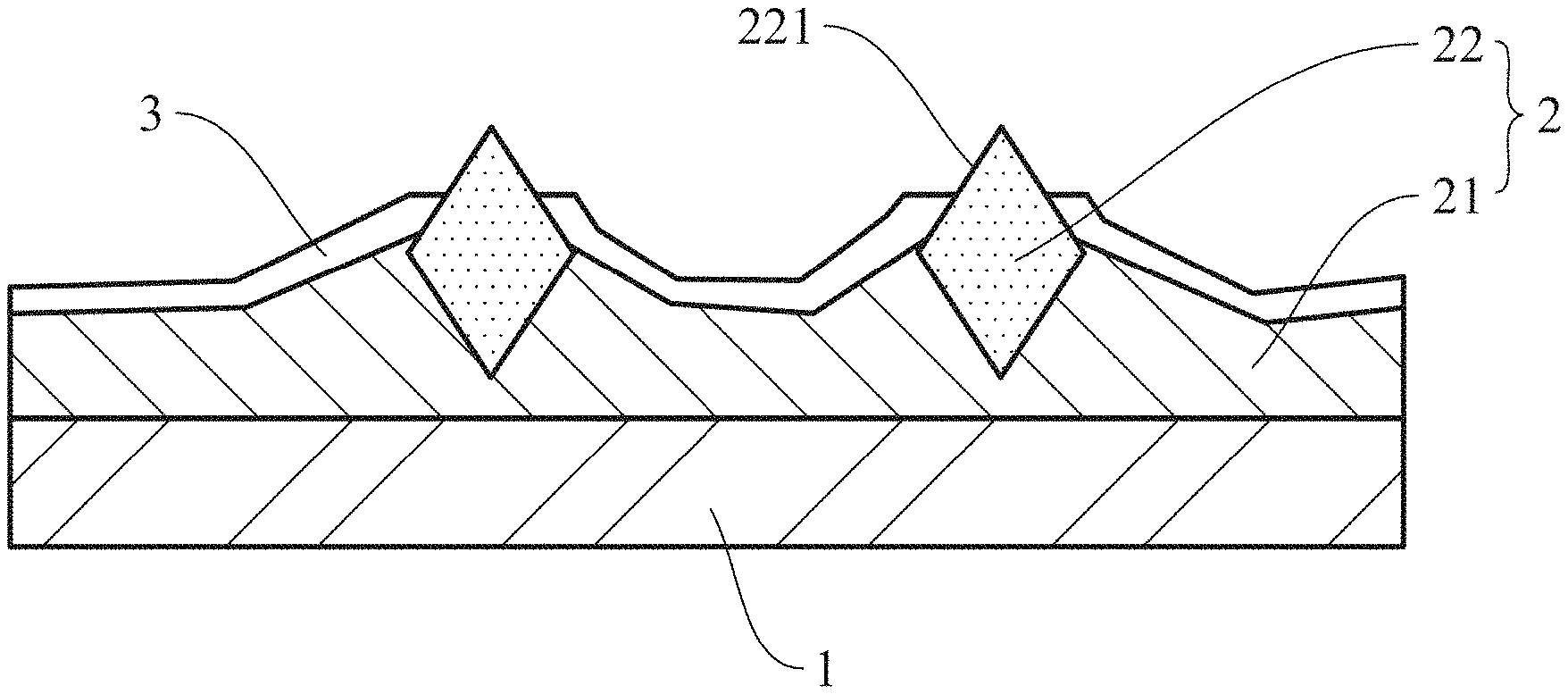
[0024] As shown in FIG. 1, the polishing pad conditioner of the present invention includes a substrate 1, an abrasive layer 2 and a protective layer 3. The abrasive layer 2 covers the surface of the substrate 1. The abrasive layer 2 includes a bonding layer 21 and a plurality of abrasive particles 22 embedded in the bonding layer 21. Each of the abrasive particles 22 has a protrusion 221 exposed out of the bonding layer 21, and the protrusion 221 has been subjected to an insulation treatment. The protective layer 3 covers the surface of the bonding layer 21, and the protrusion 221 is exposed outside the protective layer 3.
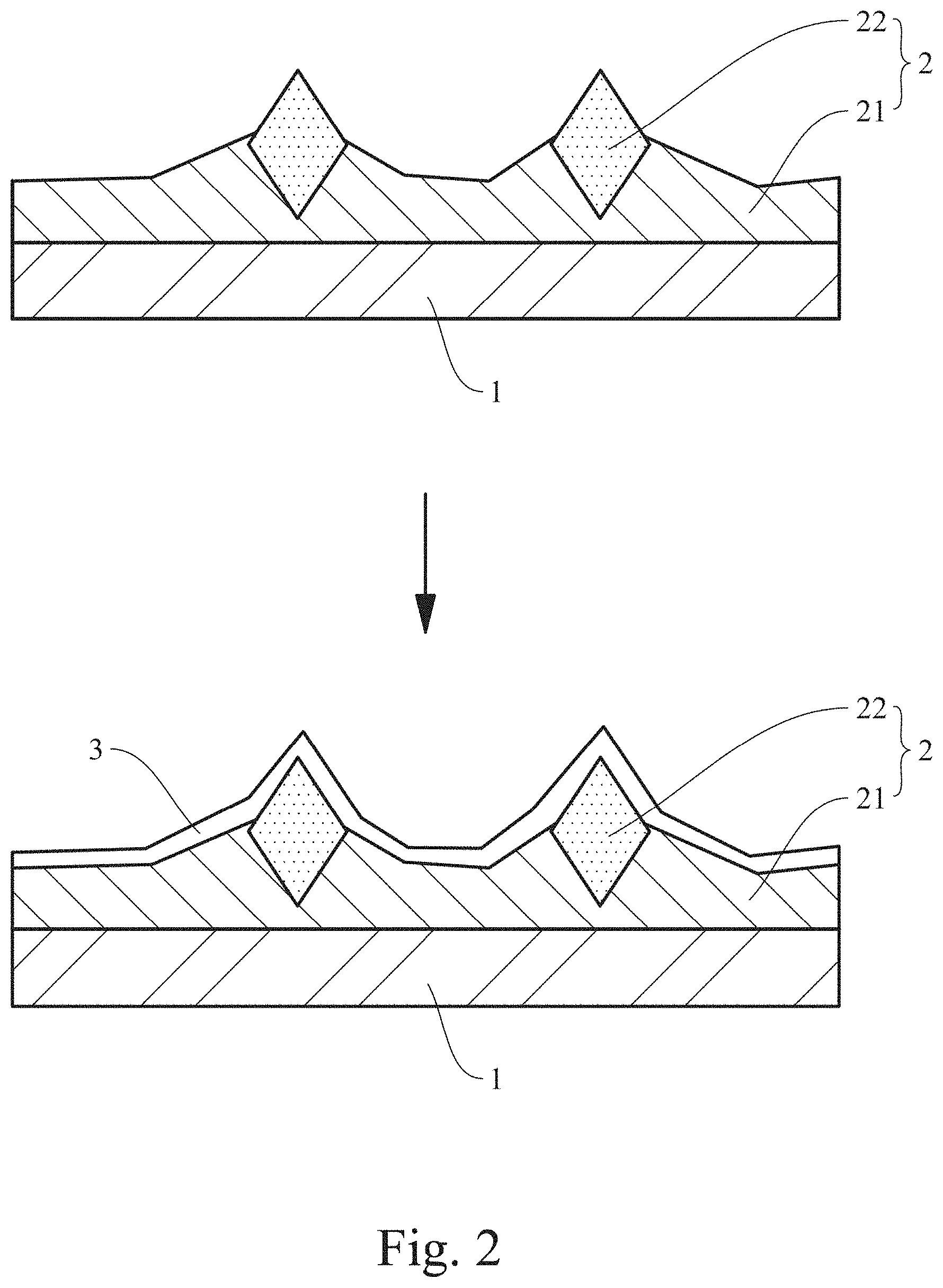
[0025] FIG. 2 provides a method for manufacturing a polishing pad conditioner of a comparative example. After the abrasive particles 22 are embedded in the bonding layer 21, a protective layer 3 is coated on the surfaces of the abrasive particles 22 and the bonding layer 21. However, the inventor found after many experiments that when manufacturing a polishing pad conditioner, no matter what bonding method (such as brazing, electroplating/electrodeposition or sintering) is used to inlay and fix the abrasive particles 22 on the bonding layer 21, since the brazing, electroplating or sintering material remains on the abrasive particles 22, the abrasive particles 22 will become conductive after being fixed on the bonding layer 21. Therefore, when the protective layer 3 is covered on the bonding layer 21 by coating or electrodeposition in the next step, the abrasive particles 22 are covered by the protective layer 3 due to their conductivity and cannot be exposed outside the protective layer 3. Compared with the polishing pad conditioner without the protective layer 3, the cutting rate of the polishing pad conditioner with the protective layer 3 is reduced because the abrasive particles 22 are covered by the protective layer 3, thereby reducing the overall cutting rate of the polishing pad conditioner. Moreover, the protective layer 3 covering the abrasive particles 22 is easy to peel off during the polishing pad conditioner dressing the polishing pad, causing impurities to fall on the polishing pad, which affects the polishing quality.
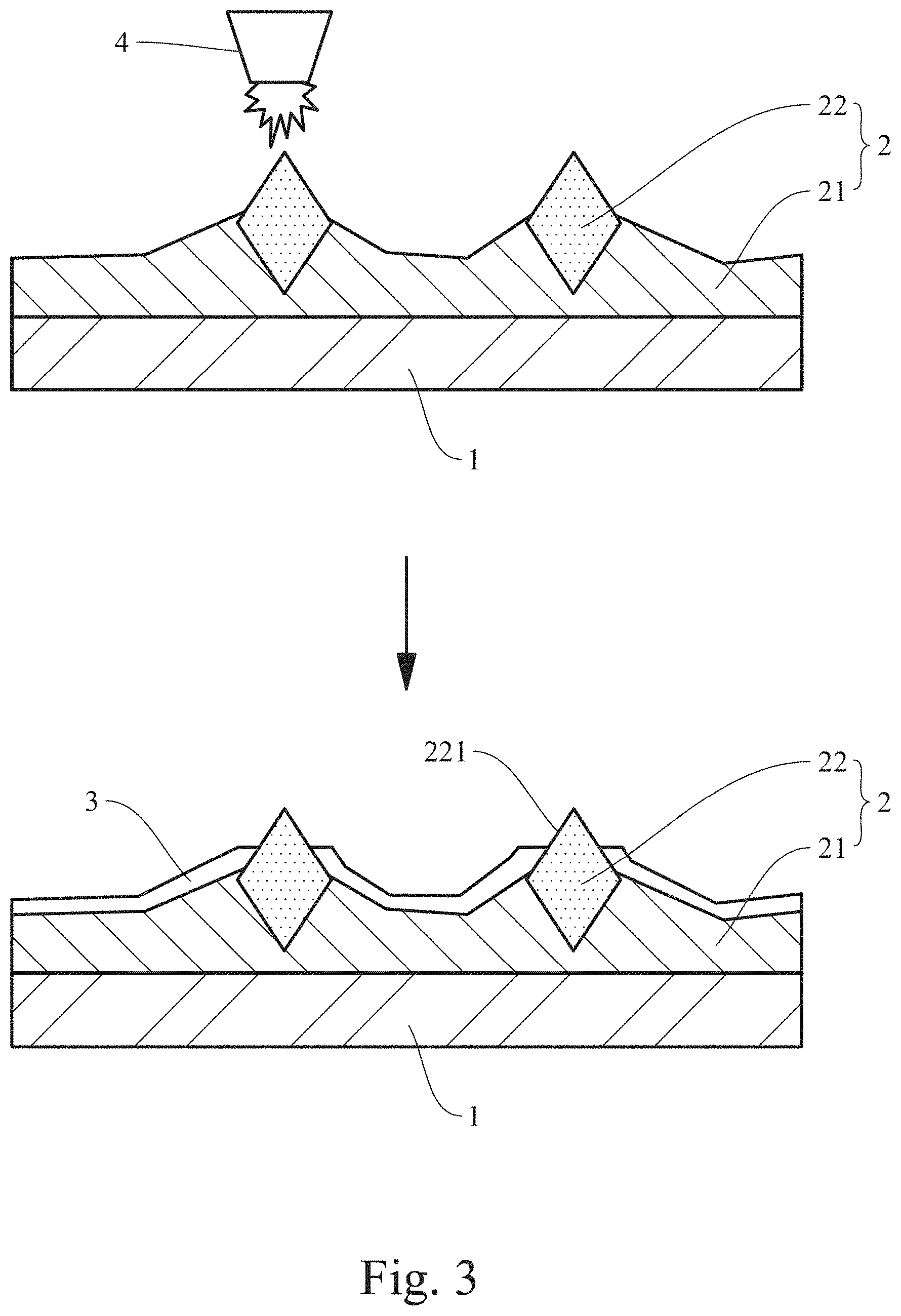
[0026] Different from the manufacturing method of the polishing pad conditioner of the comparative example, the manufacturing method of the polishing pad conditioner of the present invention is shown in FIG. 3, and the steps include: (a) providing a substrate 1; (b) forming an abrasive layer 2 on the surface of the substrate 1, wherein the abrasive layer 2 includes a bonding layer 21 and a plurality of abrasive particles 22 embedded in the bonding layer 21, and each of the abrasive particles 22 has a protrusion 221 exposed above the bonding layer 21; (c) performing an insulation treatment on the protrusion 221 (the insulation treatment shown in FIG. 4 takes plasma as an example, and the plasma nozzle 4 is used to spray the protrusion 221 for insulation treatment, but the insulation treatment of the invention is not limited to the use of plasma); and (d) electrodepositing a protective layer 3 on the surface of the bonding layer 21, and the protrusion 221 after insulation treatment is exposed outside the protective layer 3. Since the protrusion 221 is insulated in step (c), its surface has been completely insulated. When the protective layer 3 is subsequently electrodeposited in step (d), since electrodeposition transfers the charged resin particles in the solution to the surface of the oppositely charged electrode under the action of an electric field, and the surface of the protrusion 221 is insulated, the protective layer 3 cannot be formed on the surface of the protrusion 221. As a result, the protrusion 221 will be exposed outside the protective layer 3, so that the abrasive particles 22 can maintain the original cutting rate, and the protective layer 3 will not be peeled off during polishing to generate impurities. Moreover, since the protective layer 3 covers the bonding layer 21, the bonding layer 21 can be protected from being damaged by friction during polishing, so that the bonding layer 21 can firmly hold the abrasive particles 221 and prevent the abrasive particles 221 from falling off or being out of place. In addition, the polishing slurry in CMP is usually corrosive, such as an acid etching solution, while the protective layer 3 can protect the bonding layer 21 from being corroded by the etching solution to precipitate metals (such as nickel) and prevent contamination.
[0027] After testing, the polishing pad conditioner of the present invention has a cutting rate (CR.sub.completed). Compared with the cutting rate (CR.sub.initial) of a polishing pad conditioner that is not covered with the protective layer 3 (i.e., the bonding layer 21 is not covered with the protective layer 3), the variation rate of the cutting rate conforms to the following formula:
( C .times. .times. R initial - C .times. .times. R completed ) C .times. .times. R initial .times. 100 .times. % < 10 .times. % , ##EQU00002##
that is, the variation rate between the cutting rate (CR.sub.completed) and the cutting rate (CR.sub.initial) of the polishing pad conditioner that is not covered with a protective layer is less than 10%. In the polishing pad conditioner manufactured by the manufacturing method of the polishing pad conditioner of the present invention, electrodepositing the protective layer 3 on the bonding layer 21 has little effect on the cutting rate of the polishing pad conditioner. The cutting rate of the polishing pad conditioner of the invention is 300 .mu.m/hr or more, preferably 320 .mu.m/hr or more, and more preferably 330 .mu.m/hr or more. The above-mentioned cutting rate is merely exemplary and not restrictive. Those with ordinary knowledge in the field of the invention can adjust according to requirements to obtain the required cutting rate of the polishing pad conditioner.
[0028] The materials and manufacturing methods that can be used to construct the polishing pad conditioner of the present invention will be described below. It should be noted that the materials and techniques disclosed herein are only exemplary, and other materials and techniques not mentioned can be used without departing from the scope of the invention.
[0029] In the polishing pad conditioner of the present invention, the substrate 1 is composed of one or more of stainless steel, metal material, plastic material, and ceramic material. In fact, as long as the substrate 1 can support the abrasive layer 2. The preferred material can be a metal substrate, a metal alloy substrate, a stainless steel substrate or a mold steel substrate. Specifically, the metal substrate includes, but is not limited to, copper, iron, aluminum, titanium, or tin; and the metal alloy substrate includes, but is not limited to, iron alloy, copper alloy, aluminum alloy, titanium alloy, or magnesium alloy.
[0030] In the polishing pad conditioner of the present invention, the bonding layer 21 is the interlayer used to carry the abrasive particles 22 and is attached to the substrate 1, and the abrasive particles 22 are mainly embedded and fixed on the bonding layer 21. The bonding layer 21 can be formed by various different methods, such as resin organic bonding, electroplating, brazing and electrodeposition. The material of the bonding layer 21 includes brazing material, electroplating material, ceramic material, metal material or polymer material, and the invention is not limited to these. Specifically, the brazing material, electroplating material or metal material includes at least one selected from the group consisting of iron, cobalt, nickel, chromium, manganese, silicon, aluminum, and combinations thereof. The polymer material includes epoxy resin, polyester resin, polyacrylic resin or phenol resin. The ceramic material includes various metal oxides, nitrides, carbides, borides, silicides, or combinations thereof, such as silicon carbide, silicon nitride, aluminum nitride, aluminum oxide, titanium carbide, titanium boride, or boron carbide.
[0031] In the polishing pad conditioner of the present invention, the abrasive particles 22 are at least one abrasive particles 22 selected from a group consisting of natural diamond, synthetic diamond, polycrystalline diamond, cubic boron nitride, aluminum oxide, and silicon carbide. The "protrusion 221 of the abrasive particle 22" referred to herein is the part of the upper end of the abrasive particle 22 that is not covered by the protective layer 3, and its shape can be, but is not limited to, a pyramid shape, a cone shape, a circular arc shape, a cylinder shape, a knife edge shape, or a prism shape.
[0032] Herein, "the insulation treatment of the protrusion 221" means that when the abrasive particles 22 are inlaid and fixed on the bonding layer 21 through the bonding process, the protrusion 221 of the abrasive particle 22 is made conductive due to the brazing, electroplating or sintering material remaining on the protrusion 221 during the bonding process, and therefore the insulation treatment is further applied to the protrusion 221 after the bonding process. The insulation treatment includes physical insulation or chemical insulation. The physical insulation includes sandblasting insulation or plasma insulation, and the principle is to use sandblasting or plasma to remove the conductive material on the protrusion 221 to make it non-conductive. The particle size of the sandblasting particles used in the sandblasting insulation is about 50-200 .mu.m. The temperature used in the plasma insulation is about 150-350.degree. C. The chemical insulation includes insulation by an etching method, which uses a chemical solution to etch and remove the conductive material on the protrusion 221. The chemical solution includes, but is not limited to, nitric acid, aqua regia, hydrofluoric acid, sulfuric acid, hydrogen peroxide, perchloric acid, hydrochloric acid, ferric chloride, acetic acid, ammonium cerium nitrate, potassium chloride, potassium iodide, ammonium persulfate, ammonium chloride, or a combination thereof. The chemical solution preferably contains at least one selected from the group consisting of nitric acid, aqua regia, hydrofluoric acid, sulfuric acid, hydrogen peroxide, perchloric acid, hydrochloric acid, ferric chloride, acetic acid, and ammonium cerium nitrate. After the above-mentioned insulation treatment, the surface of the protrusion 221 is insulated and not charged, and the protective layer 3 cannot be electrodeposited on the surface of the protrusion 221 subsequently, so the protrusion 221 can be exposed outside the protective layer 3.
[0033] In the polishing pad conditioner of the present invention, the protective layer 3 is preferably formed of an electrodeposition coating composition. Electrodeposition is a kind of surface treatment in which the polishing pad conditioner is immersed in the electrodeposition coating composition, and the abrasive layer 2 is placed between the electrodes and provided with current, so that the electrodeposition coating composition is deposited on the surface of the bonding layer 21 by electrical action to form a uniform protective layer 3. Although other surface treatment methods (such as spray coating or spin coating) can also be used, the use of electrodeposition coating can obtain a uniform and thin protective layer 3. The protective layer 3 with a thin thickness can help maintain a considerable height distance between the abrasive particles 22 and the protective layer 3 and the cutting rate of the abrasive particles 22. The thickness of the protective layer 3 may preferably be, but is not limited to, 10-30 .mu.m, and the thickness difference of each position is preferably controlled to be 1.0-3.0 .mu.m, and more preferably 1.5 .mu.m. The electrodeposition coating composition includes a main resin, and the main resin is epoxy resin, acrylic resin, polybutadiene resin, polyester resin or polyamide resin, specifically, amine modified epoxy resin (e.g., modified epoxy resin containing diethyltriamine), acrylic resin containing carboxyl and hydroxyl groups, or epoxidized polybutadiene resin, and the invention is not limited to these.
EXAMPLE
[0034] The following example provides a manufacturing method of the polishing pad conditioner of the present invention. It should be understood that the example is for illustration only and is not intended to limit the invention.
Example--Polishing Pad Conditioner of the Present Invention in which the Protrusions are Insulated
[0035] Molten nickel-chromium alloy and diamond particles were used to form an abrasive layer on the surface of a stainless steel. The molten nickel-chromium alloy was coated on part of the oblique side of each diamond particle by surface tension to embed, support, and fix the diamond particle on the surface of a stainless steel. Plasma insulation treatment was applied to the protrusion of each diamond particle to insulate the surface of the protrusion. Finally, an epoxy resin (PPG Industries Inc.) was electrodeposited on the surface of the bonding layer to form a protective layer to obtain the polishing pad conditioner of the present invention.
Comparative Example 1--Polishing Pad Conditioner with Uninsulated Protrusions
[0036] The manufacturing method of the polishing pad conditioner of Comparative Example 1 was the same as that of the Example, except that the protrusion of each diamond particle in Comparative Example 1 was not insulated.
[0037] Test 1--Cutting Rate
[0038] The cutting rate of the polishing pad conditioner of the Example and that of Comparative Example 1 were tested respectively, and the variation rate of cutting rate is calculated by the following formula:
( C .times. .times. R initial - C .times. .times. R completed ) C .times. .times. R initial .times. 100 .times. % ; ##EQU00003##
and the results are shown in Table 1.
TABLE-US-00001 TABLE 1 Cutting rate when not Cutting rate when covered Variation covered with protective with protective layer rate of layer (CR.sub.initial, .mu.m/hr) (CR.sub.completed, .mu.m/hr) cutting rate Example 325 321 1.23% Comparative 318 202 36.48% Example 1
[0039] As shown in Table 1, after the bonding layer of the polishing pad conditioner of the Example was covered by the protective layer, the variation rate of the cutting rate was less than 10%, which means that the cutting rate of the polishing pad conditioner of the Example would not decrease even if it was covered by the protective layer. In contrast, after the abrasive layer of the polishing pad conditioner of Comparative Example 1 was covered by the protective layer, the variation rate of the cutting rate was greater than 10%, which decreased from 318 .mu.m/hr to 202 .mu.m/hr. The difference between the Example and the Comparative Example 1 lies in whether the protective layer covered the protrusions of the diamond particles. It can be seen from Comparative Example 1 that when the protective layer covers the protrusions, the cutting rate of the polishing pad conditioner is greatly reduced.
[0040] Test 2--Photographed the Surface of the Abrasive Layer of the Polishing Pad Conditioner by Scanning Electron Microscope (SEM)
[0041] A scanning electron microscope (SEM) was used to photograph the surface of the abrasive layer of the polishing pad conditioner of the Example and that of Comparative Example 1, and the results are shown in FIG. 4. FIG. 4(a) is the surface of the abrasive layer of the polishing pad conditioner of Comparative Example 1, and FIG. 4(b) is the surface of the abrasive layer of the polishing pad conditioner of the Example. As shown in FIG. 4(b), the protrusions of the abrasive particles of the polishing pad conditioner of the Example are insulated, and the protective layer cannot be electrodeposited on the surface, thus forming a sharper cutting surface. In contrast, as shown in FIG. 4(a), the protrusions of the abrasive particles of the polishing pad conditioner of Comparative Example 1 are not insulated, and the protective layer is electrodeposited on the surface, thus forming a rounder but not sharp cutting surface.
Comparative Example 2--Polishing Pad Conditioner without Protective Layer
[0042] Molten nickel-chromium alloy and diamond particles were used to form an abrasive layer on the surface of a stainless steel. The molten nickel-chromium alloy was coated on part of the oblique side of each diamond particle by surface tension so as to embed, support and fix the diamond particle to obtain a polishing pad conditioner without a protective layer.
[0043] Test 3--Comparison of Metal Precipitation
[0044] The polishing pad conditioner of the Example and that of Comparative Example 2 were soaked in 3% nitric acid solution, respectively. After 24 hours, the amount of metal in the 3% nitric acid solution after soaking was tested, and the results are shown in Table 2.
TABLE-US-00002 TABLE 2 Cr Fe Ni Co (ppb) (ppb) (ppb) (ppb) 3% HNO.sub.3 16 90 4 n.d Example 39 117 18 3 Comparative 147,071 176,703 334,063 885 Example 2
[0045] As shown in Table 2, 3% nitric acid solution originally contained low concentrations of chromium, iron, nickel and cobalt. After the polishing pad conditioner of the Example was soaked, although chromium, iron, nickel, and cobalt were precipitated, the concentrations were not high. In contrast, the polishing pad conditioner of Comparative Example 2 had very high precipitation concentrations of chromium, iron, nickel, and cobalt because there was no protective layer.
[0046] According to the above Example, the polishing pad conditioner manufactured by insulating the protrusions has no protective layer covering the protrusions of diamond particles, so the cutting rate can be maintained without reducing the polishing effect, and the polishing ability of the polishing pad conditioner is maintained. In addition, when the bonding layer of the polishing pad conditioner is covered with a protective layer, the metal of the bonding layer can be protected from precipitation.
[0047] In summary, the polishing pad conditioner of the present invention has a protective layer, which can prevent the metal (e.g., nickel) of the bonding layer from being precipitated during the CMP process to prevent contamination, and protect the bonding layer from being damaged by abrasion and hold the abrasive particles, prevent the abrasive particles from falling off or out of position, and prevent the protective layer from peeling off during polishing pad conditioner dressing the polishing pad and causing impurities to fall on the polishing pad, thereby maintaining the polishing effect and prolonging the service life. In addition, the manufacturing method of the polishing pad conditioner of the present invention uses insulation treatment and electrodeposition. The insulation treatment can insulate the protrusions of the abrasive particles so that the protective layer will not cover the protrusions during subsequent electrodeposition. The protective layer formed by electrodeposition has the advantages of thin thickness and uniform distribution, so that the height of the protrusion can be maintained, i.e., the cutting rate of the polishing pad conditioner can be maintained. Therefore, the polishing pad conditioner of the invention is suitable for CMP and has industrial applicability.
[0048] The above is the detailed description of the present invention. However, the above is merely the preferred Example of the invention and cannot be the limitation to the implement scope of the invention, which means the variation and modification according to the present invention may still fall into the scope of the invention.
* * * * *
D00000
D00001
D00002
D00003
D00004
XML
uspto.report is an independent third-party trademark research tool that is not affiliated, endorsed, or sponsored by the United States Patent and Trademark Office (USPTO) or any other governmental organization. The information provided by uspto.report is based on publicly available data at the time of writing and is intended for informational purposes only.
While we strive to provide accurate and up-to-date information, we do not guarantee the accuracy, completeness, reliability, or suitability of the information displayed on this site. The use of this site is at your own risk. Any reliance you place on such information is therefore strictly at your own risk.
All official trademark data, including owner information, should be verified by visiting the official USPTO website at www.uspto.gov. This site is not intended to replace professional legal advice and should not be used as a substitute for consulting with a legal professional who is knowledgeable about trademark law.