Optical Sensing Systems And Methods For Sensor Enabled Wound Dressings And Systems
Gunning; Paul ; et al.
U.S. patent application number 17/310319 was filed with the patent office on 2022-04-14 for optical sensing systems and methods for sensor enabled wound dressings and systems. The applicant listed for this patent is Smith & Nephew PLC. Invention is credited to Paul Gunning, Edward Yerbury Hartwell, Marcus Damian Phillips, Felix Clarence Quintanar, Charlotte Rose Urwin.
| Application Number | 20220110797 17/310319 |
| Document ID | / |
| Family ID | 1000006089845 |
| Filed Date | 2022-04-14 |


| United States Patent Application | 20220110797 |
| Kind Code | A1 |
| Gunning; Paul ; et al. | April 14, 2022 |
OPTICAL SENSING SYSTEMS AND METHODS FOR SENSOR ENABLED WOUND DRESSINGS AND SYSTEMS
Abstract
In some cases, a method of coating a wound dressing includes coating a wound facing side of a substantially flexible substrate of the wound dressing with a coating, the wound facing side of the substrate supporting at least one optical sensor and reducing and/or controlling surface texture of the coating to improve detection by the at least one optical sensor. In some cases, a wound dressing includes a substantially flexible substrate supporting at least one optical sensor, the at least one optical sensor including a light source and a detector configured to sense reflected light, a void in the substrate, the void positioned between the light source and the detector, and coating applied to the substrate and covering the at least one optical sensor. The void can prevent transmission of light emitted by the light source to the detector through the coating.
| Inventors: | Gunning; Paul; (Hull, GB) ; Hartwell; Edward Yerbury; (Hull, GB) ; Phillips; Marcus Damian; (Horbury, Wakefield, GB) ; Quintanar; Felix Clarence; (Hull, GB) ; Urwin; Charlotte Rose; (Hull, GB) | ||||||||||
| Applicant: |
|
||||||||||
|---|---|---|---|---|---|---|---|---|---|---|---|
| Family ID: | 1000006089845 | ||||||||||
| Appl. No.: | 17/310319 | ||||||||||
| Filed: | January 28, 2020 | ||||||||||
| PCT Filed: | January 28, 2020 | ||||||||||
| PCT NO: | PCT/EP2020/052049 | ||||||||||
| 371 Date: | July 27, 2021 |
| Current U.S. Class: | 1/1 |
| Current CPC Class: | A61L 15/26 20130101; A61B 5/6802 20130101; A61L 2420/02 20130101; A61F 13/00051 20130101 |
| International Class: | A61F 13/00 20060101 A61F013/00; A61B 5/00 20060101 A61B005/00; A61L 15/26 20060101 A61L015/26 |
Foreign Application Data
| Date | Code | Application Number |
|---|---|---|
| Jan 30, 2019 | GB | 1901242.6 |
Claims
1. A method of coating a wound dressing, the method comprising: coating a wound facing side of a substantially flexible substrate of the wound dressing with a coating, the wound facing side of the substrate supporting at least one optical sensor; and at least one of reducing or controlling surface texture of the coating to improve detection by the at least one optical sensor by applying a film to the coating.
2. The method of claim 1, wherein at least one of reducing or controlling surface texture of the coating comprises reducing surface roughness of the coating.
3. The method of claim 1, wherein coating the wound facing side of the substantially flexible substrate of the wound dressing with the coating comprises applying the coating to the at least one optical sensor.
4. The method of claim 1, wherein the at least one optical sensor includes a light source and a detector configured to sense light reflected by a wound.
5. The method of claim 1, wherein applying the film to the coating comprises applying the film before the coating is cured.
6. The method of claim 1, wherein the film is coated with silicone.
7. The method of claim 1, wherein applying the film to the coating comprises applying a carrier coated with silicone on at least one side of the carrier, the at least one side of the carrier coated with silicone being in contact with the coating, and wherein the method further comprises removing the carrier after the coating has been cured.
8. The method of claim 1, wherein the coating is hydrophobic.
9. (canceled)
10. A wound dressing comprising: a substantially flexible substrate supporting at least one optical sensor, the at least one optical sensor comprising a light source and a detector configured to sense reflected light; a void in the substrate, the void positioned between the light source and the detector; and coating applied to the substrate and covering the at least one optical sensor, wherein the void prevents transmission of light emitted by the light source to the detector through the coating.
11. The wound dressing of claim 10, wherein the void comprises a hole or a slot in a material forming the substrate.
12. The wound dressing of claim 10, wherein the void is formed through an entire thickness of the substrate.
13. The wound dressing of claim 10, wherein a distance between the light source and the detector is not greater than 10 millimeters.
14. The wound dressing of claim 10, wherein coating does not fill an entirety of the void in the substrate.
15. A method of manufacturing a wound dressing comprising: forming a void in a substantially flexible substrate supporting at least one optical sensor, the at least one optical sensor comprising a light source and a detector configured to sense reflected light, the void positioned between the light source and the detector.
16. The method of claim 15, wherein the void comprises a hole or a slot in the substrate.
17. The method of claim 15, wherein the void is formed through an entire thickness of the substrate.
18. The method of claim 22, wherein applying the coating comprises not filling an entirety of the void in the substrate.
19. The method of claim 15 further comprising: prior to forming the void, applying coating to the substantially flexible substrate and covering the at least one optical sensor with coating.
20. The method of claim 19, wherein the void comprises a hole or a slot in the substrate.
21. The method of claim 19, wherein the void is formed through an entire thickness of the substrate.
22. The method of claim 15, further comprising: subsequently to forming the void, applying coating to the substrate and covering the at least one optical sensor with coating.
Description
FIELD
[0001] Embodiments of the present disclosure relate to apparatuses, systems, and methods for the monitoring and/or treatment of tissue with sensor-enabled wound dressings. In some embodiments, improved optical sensing techniques are described.
DESCRIPTION OF THE RELATED ART
[0002] Nearly all areas of medicine may benefit from improved information regarding the state of the tissue, organ, or system to be treated, particularly if such information is gathered in real-time during treatment, many types of treatments are still routinely performed without the use of sensor data collection. Instead, such treatments rely upon visual inspection by a caregiver or other limited means rather than quantitative sensor data. For example, in the case of wound treatment via dressings and/or negative pressure wound therapy, data collection is generally limited to visual inspection by a caregiver and often the underlying wounded tissue may be obscured by bandages or other visual impediments. Even intact, unwounded skin may have underlying damage that is not visible to the naked eye, such as a compromised vascular or deeper tissue damage that may lead to an ulcer. Similar to wound treatment, during orthopedic treatments requiring the immobilization of a limb with a cast or other encasement, only limited information is gathered on the underlying tissue. In instances of internal tissue repair, such as a bone plate, continued direct sensor-driven data collection is not performed. Further, braces and/or sleeves used to support musculoskeletal function do not monitor the functions of the underlying muscles or the movement of the limbs. Outside of direct treatments, common hospital room items such as beds and blankets could be improved by adding capability to monitor patient parameters.
[0003] Therefore, there is a need for improved sensor monitoring, particularly through the use of sensor-enabled substrates which can be incorporated into existing treatment regimes.
SUMMARY
[0004] In some cases, a method of coating a wound dressing, the method including coating a wound facing side of a substantially flexible substrate of the wound dressing with a coating, the wound facing side of the substrate supporting at least one optical sensor and at least one of reducing or controlling surface texture of the coating to improve detection by the at least one optical sensor. At least one of reducing or controlling surface texture of the coating can include applying a film to the coating.
[0005] The method of any preceding paragraphs or any of the methods disclosed herein can include one or more of the following features. At least one of reducing or controlling surface texture of the coating can include reducing surface roughness of the coating. Coating the wound facing side of the substantially flexible substrate of the wound dressing with the coating can include applying the coating to the at least one optical sensor. At least one optical sensor can include a light source and a detector configured to sense light reflected by a wound. Applying the film to the coating can include applying the film before the coating is cured. The film can be coated with silicone. Applying the film to the coating can include applying a carrier, such as film, coated with silicone on at least one side of the carrier, the at least one side of the carrier coated with silicone being in contact with the coating and further removing the carrier after the coating is cured. The coating can be hydrophobic.
[0006] In some cases, a wound dressing can be produced by the method of any of preceding claims or any of the methods disclosed herein.
[0007] In some cases, a wound dressing includes a substantially flexible substrate supporting at least one optical sensor, the at least one optical sensor comprising a light source and a detector configured to sense reflected light, a void in the substrate, the void positioned between the light source and the detector, and coating applied to the substrate and covering the at least one optical sensor. The void can prevent transmission of light emitted by the light source to the detector through the coating.
[0008] The wound dressing of any preceding paragraphs or any of the wound dressings disclosed herein can include one or more of the following features. The void can include a hole or a slot in a material forming the substrate. The void can be formed through an entire thickness of the substrate. A distance between the light source and the detector may not be greater than 10 millimeters. Coating may not fill the entirety of the void in the substrate.
[0009] In some cases, the wound dressing of any of preceding paragraphs or any of the wound dressings disclosed herein can be produced by a method of manufacturing.
[0010] In some cases, a method of manufacturing a wound dressing includes forming a void in a substantially flexible substrate supporting at least one optical sensor, the at least one optical sensor comprising a light source and a detector configured to sense reflected light, the void positioned between the light source and the detector. The method can further include, subsequently, applying coating to the substrate and covering the at least one optical sensor with coating.
[0011] The method of any preceding paragraphs or any of the methods disclosed herein can include one or more of the following features. The void can include a hole or a slot in the substrate. The void can be formed through an entire thickness of the substrate. Applying the coating can include not filling an entirety of the void in the substrate.
[0012] In some cases, a method of manufacturing a wound dressing includes applying coating to a substantially flexible substrate supporting at least one optical sensor and covering the at least one optical sensor with coating, the at least one optical sensor comprising a light source and a detector configured to sense reflected light. The method can further include, subsequently, forming a void in the substrate, the void positioned between the light source and the detector.
[0013] The method of any preceding paragraphs or any of the methods disclosed herein can include one or more of the following features. The void can include a hole or a slot in the substrate. The void can be formed through an entire thickness of the substrate.
BRIEF DESCRIPTION OF THE DRAWINGS
[0014] Embodiments of the present disclosure will now be described hereinafter, by way of example only, with reference to the accompanying drawings in which:
[0015] FIG. 1A illustrates a negative pressure wound treatment system according to some embodiments;
[0016] FIG. 1B illustrates a wound dressing according to some embodiments;
[0017] FIG. 2 illustrates a sensor array illustrating the sensor placement incorporated into a wound dressing according to some embodiments;
[0018] FIG. 3 illustrates a flexible sensor array incorporated into a perforated wound contact layer according to some embodiments;
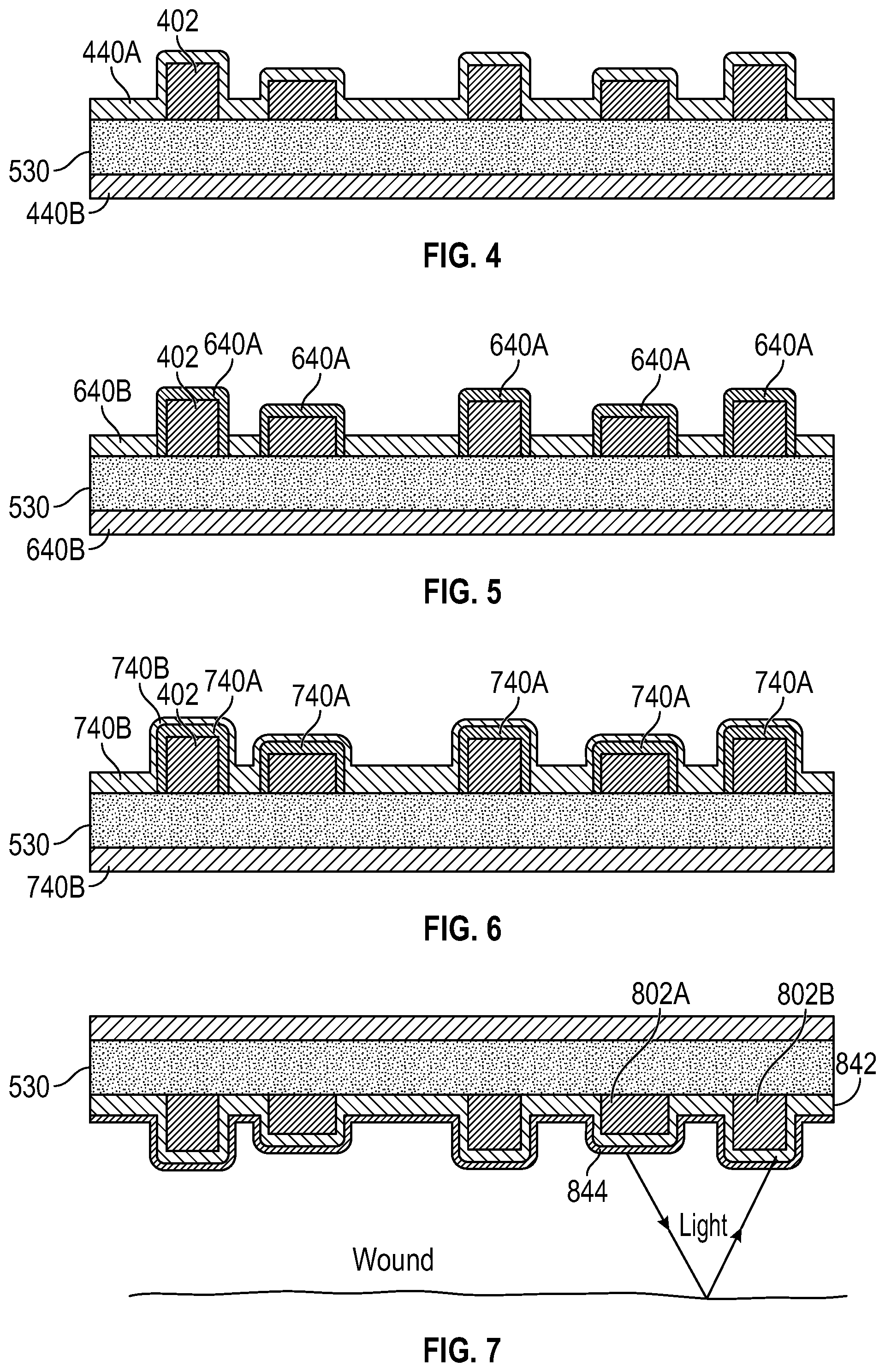
[0019] FIG. 4 illustrates coating(s) of a wound dressing according to some embodiments;
[0020] FIG. 5 illustrates coating a wound dressing with two biocompatible coatings according to some embodiments;
[0021] FIG. 6 illustrates coating a wound dressing with a biocompatible coating according to some embodiments;
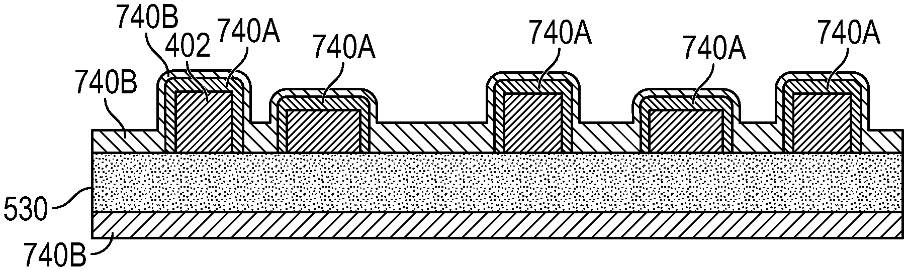
[0022] FIG. 7 optical sensing with coated wound dressing according to some embodiments;
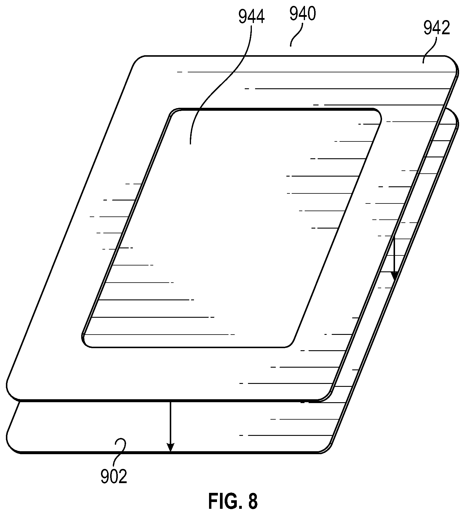
[0023] FIG. 8 illustrates application of a film to coating in a wound dressing according to some embodiments;
[0024] FIGS. 9A-9B illustrate optical detection charts according to some embodiments; and
[0025] FIGS. 10A-10B illustrate a void in a wound dressing substrate according to some embodiments.
DETAILED DESCRIPTION
[0026] Embodiments disclosed herein relate to apparatuses and methods of at least one of monitoring or treating biological tissue with sensor-enabled substrates. The embodiments disclosed herein are not limited to treatment or monitoring of a particular type of tissue or injury, instead the sensor-enabled technologies disclosed herein are broadly applicable to any type of therapy that may benefit from sensor-enabled substrates. Some implementations utilize sensors and data collection relied upon by health care providers to make both diagnostic and patient management decisions.
[0027] Some embodiments disclosed herein relate to the use of sensors mounted on or embedded within substrates configured to be used in the treatment of both intact and damaged human or animal tissue. Such sensors may collect information about the surrounding tissue and transmit such information to a computing device or a caregiver to be utilized in further treatment. In certain embodiments, such sensors may be attached to the skin anywhere on the body, including areas for monitoring arthritis, temperature, or other areas that may be prone to problems and require monitoring. Sensors disclosed herein may also incorporate markers, such as radiopaque markers, to indicate the presence of the device, for example prior to performing an MRI or other technique.
[0028] The sensor embodiments disclosed herein may be used in combination with clothing. Non-limiting examples of clothing for use with embodiments of the sensors disclosed herein include shirts, pants, trousers, dresses, undergarments, outer-garments, gloves, shoes, hats, and other suitable garments. In certain embodiments, the sensor embodiments disclosed herein may be welded into or laminated into/onto the particular garments. The sensor embodiments may be printed directly onto the garment and/or embedded into the fabric. Breathable and printable materials such as microporous membranes may also be suitable.
[0029] Sensor embodiments disclosed herein may be incorporated into cushioning or bed padding, such as within a hospital bed, to monitor patient characteristics, such as any characteristic disclosed herein. In certain embodiments, a disposable film containing such sensors could be placed over the hospital bedding and removed/replaced as needed.
[0030] In some implementations, the sensor embodiments disclosed herein may incorporate energy harvesting, such that the sensor embodiments are self-sustaining. For example, energy may be harvested from thermal energy sources, kinetic energy sources, chemical gradients, or any suitable energy source.
[0031] The sensor embodiments disclosed herein may be utilized in rehabilitation devices and treatments, including sports medicine. For example, the sensor embodiments disclosed herein may be used in braces, sleeves, wraps, supports, and other suitable items. Similarly, the sensor embodiments disclosed herein may be incorporated into sporting equipment, such as helmets, sleeves, and/or pads. For example, such sensor embodiments may be incorporated into a protective helmet to monitor characteristics such as acceleration, which may be useful in concussion diagnosis.
[0032] The sensor embodiments disclosed herein may be used in coordination with surgical devices, for example, the NAVIO surgical system by Smith & Nephew Inc. In some implementations, the sensor embodiments disclosed herein may be in communication with such surgical devices to guide placement of the surgical devices. In some implementations, the sensor embodiments disclosed herein may monitor blood flow to or away from the potential surgical site or ensure that there is no blood flow to a surgical site. Further surgical data may be collected to aid in the prevention of scarring and monitor areas away from the impacted area.
[0033] To further aid in surgical techniques, the sensors disclosed herein may be incorporated into a surgical drape to provide information regarding tissue under the drape that may not be immediately visible to the naked eye. For example, a sensor embedded flexible drape may have sensors positioned advantageously to provide improved area-focused data collection. In certain implementations, the sensor embodiments disclosed herein may be incorporated into the border or interior of a drape to create fencing to limit/control the surgical theater.
[0034] Sensor embodiments as disclosed herein may also be utilized for pre-surgical assessment. For example, such sensor embodiments may be used to collect information about a potential surgical site, such as by monitoring skin and the underlying tissues for a possible incision site. For example, perfusion levels or other suitable characteristics may be monitored at the surface of the skin and deeper in the tissue to assess whether an individual patient may be at risk for surgical complications. Sensor embodiments such as those disclosed herein may be used to evaluate the presence of microbial infection and provide an indication for the use of antimicrobials. Further, sensor embodiments disclosed herein may collect further information in deeper tissue, such as identifying pressure ulcer damage and/or the fatty tissue levels.
[0035] The sensor embodiments disclosed herein may be utilized in cardiovascular monitoring. For example, such sensor embodiments may be incorporated into a flexible cardiovascular monitor that may be placed against the skin to monitor characteristics of the cardiovascular system and communicate such information to another device and/or a caregiver. For example, such a device may monitor pulse rate, oxygenation of the blood, and/or electrical activity of the heart. Similarly, the sensor embodiments disclosed herein may be utilized for neurophysiological applications, such as monitoring electrical activity of neurons.
[0036] The sensor embodiments disclosed herein may be incorporated into implantable devices, such as implantable orthopedic implants, including flexible implants. Such sensor embodiments may be configured to collect information regarding the implant site and transmit this information to an external source. In some embodiments, an internal source may also provide power for such an implant.
[0037] The sensor embodiments disclosed herein may also be utilized for monitoring biochemical activity on the surface of the skin or below the surface of the skin, such as lactose buildup in muscle or sweat production on the surface of the skin. In some embodiments, other characteristics may be monitored, such as glucose concentration, urine concentration, tissue pressure, skin temperature, skin surface conductivity, skin surface resistivity, skin hydration, skin maceration, and/or skin ripping.
[0038] Sensor embodiments as disclosed herein may be incorporated into Ear, Nose, and Throat (ENT) applications. For example, such sensor embodiments may be utilized to monitor recovery from ENT-related surgery, such as wound monitoring within the sinus passage.
[0039] Sensor embodiments disclosed herein may encompass sensor printing technology with encapsulation, such as encapsulation with a polymer film. Such a film may be constructed using any polymer described herein, such as polyurethane. Encapsulation of the sensor embodiments may provide waterproofing of the electronics and protection from local tissue, local fluids, and other sources of potential damage.
[0040] In certain embodiments, the sensors disclosed herein may be incorporated into an organ protection layer. Such a sensor-embedded organ protection layer may both protect the organ of interest and confirm that the organ protection layer is in position and providing protection. Further, a sensor-embedded organ protection layer may be utilized to monitor the underlying organ, such as by monitoring blood flow, oxygenation, and other suitable markers of organ health. In some embodiments, a sensor-enabled organ protection layer may be used to monitor a transplanted organ, such as by monitoring the fat and muscle content of the organ. Further, sensor-enabled organ protection layers may be used to monitor an organ during and after transplant, such as during rehabilitation of the organ.
[0041] The sensor embodiments disclosed herein may be incorporated into treatments for wounds (disclosed in greater detail below) or in a variety of other applications. Non-limiting examples of additional applications for the sensor embodiments disclosed herein include: monitoring and treatment of intact skin, cardiovascular applications such as monitoring blood flow, orthopedic applications such as monitoring limb movement and bone repair, neurophysiological applications such as monitoring electrical impulses, and any other tissue, organ, system, or condition that may benefit from improved sensor-enabled monitoring.
Wound Therapy
[0042] Some embodiments disclosed herein relate to wound therapy for a human or animal body. Therefore, any reference to a wound herein can refer to a wound on a human or animal body, and any reference to a body herein can refer to a human or animal body. The disclosed technology embodiments may relate to preventing or minimizing damage to physiological tissue or living tissue, or to the treatment of damaged tissue (for example, a wound as described herein) wound with or without reduced pressure, including for example a source of negative pressure and wound dressing components and apparatuses. The apparatuses and components comprising the wound overlay and packing materials or internal layers, if any, are sometimes collectively referred to herein as dressings. In some embodiments, the wound dressing can be provided to be utilized without reduced pressure.
[0043] Some embodiments disclosed herein relate to wound therapy for a human or animal body. Therefore, any reference to a wound herein can refer to a wound on a human or animal body, and any reference to a body herein can refer to a human or animal body. The disclosed technology embodiments may relate to preventing or minimizing damage to physiological tissue or living tissue, or to the treatment of damaged tissue (for example, a wound as described herein).
[0044] As used herein the expression "wound" may include an injury to living tissue may be caused by a cut, blow, or other impact, typically one in which the skin is cut or broken. A wound may be a chronic or acute injury. Acute wounds occur as a result of surgery or trauma. They move through the stages of healing within a predicted timeframe. Chronic wounds typically begin as acute wounds. The acute wound can become a chronic wound when it does not follow the healing stages resulting in a lengthened recovery. It is believed that the transition from acute to chronic wound can be due to a patient being immuno-compromised.
[0045] Chronic wounds may include for example: venous ulcers (such as those that occur in the legs), which account for the majority of chronic wounds and mostly affect the elderly, diabetic ulcers (for example, foot or ankle ulcers), peripheral arterial disease, pressure ulcers, or epidermolysis bullosa (EB).
[0046] Examples of other wounds include, but are not limited to, abdominal wounds or other large or incisional wounds, either as a result of surgery, trauma, sterniotomies, fasciotomies, or other conditions, dehisced wounds, acute wounds, chronic wounds, subacute and dehisced wounds, traumatic wounds, flaps and skin grafts, lacerations, abrasions, contusions, burns, diabetic ulcers, pressure ulcers, stoma, surgical wounds, trauma and venous ulcers or the like.
[0047] Wounds may also include a deep tissue injury. Deep tissue injury is a term proposed by the National Pressure Ulcer Advisory Panel (NPUAP) to describe a unique form of pressure ulcers. These ulcers have been described by clinicians for many years with terms such as purple pressure ulcers, ulcers that are likely to deteriorate and bruises on bony prominences.
[0048] Wound may also include tissue at risk of becoming a wound as discussed herein. For example, tissue at risk may include tissue over a bony protuberance (at risk of deep tissue injury/insult) or pre-surgical tissue (for example, knee tissue) that may has the potential to be cut (for example, for joint replacement/surgical alteration/reconstruction).
[0049] Some embodiments relate to methods of treating a wound with the technology disclosed herein in conjunction with one or more of the following: advanced footwear, turning a patient, offloading (such as, offloading diabetic foot ulcers), treatment of infection, systemix, antimicrobial, antibiotics, surgery, removal of tissue, affecting blood flow, physiotherapy, exercise, bathing, nutrition, hydration, nerve stimulation, ultrasound, electrostimulation, oxygen therapy, microwave therapy, active agents ozone, antibiotics, antimicrobials, or the like.
[0050] Alternatively or additionally, a wound may be treated using topical negative pressure (TNP) and/or traditional advanced wound care, which is not aided by the using of applied negative pressure (may also be referred to as non-negative pressure therapy).
[0051] Advanced wound care may include use of an absorbent dressing, an occlusive dressing, use of an antimicrobial and/or debriding agents in a wound dressing or adjunct, a pad (for example, a cushioning or compressive therapy, such as stockings or bandages), or the like.
[0052] In some embodiments, a wound dressing comprises one or more absorbent layer(s). The absorbent layer may be a foam or a superabsorbent.
[0053] In some embodiments, the disclosed technology may be used in conjunction with a non-negative pressure dressing. A non-negative pressure wound dressing suitable for providing protection at a wound site may comprise an absorbent layer for absorbing wound exudate and an obscuring element for at least partially obscuring a view of wound exudate absorbed by the absorbent layer in use. The obscuring element may be partially translucent. The obscuring element may be a masking layer.
[0054] In some embodiments, the non-negative pressure wound dressing as disclosed herein comprises the wound contact layer and the absorbent layer overlies the wound contact layer. The wound contact layer can carry an adhesive portion for forming a substantially fluid tight seal over the wound.
[0055] In some embodiments, the wound dressing as disclosed herein further comprises layer of a superabsorbent fiber, or a viscose fiber or a polyester fiber.
[0056] In some embodiments, the wound dressing as disclosed herein further comprises a backing layer. The backing layer may be a transparent or opaque film. Typically the backing layer comprises a polyurethane film (typically a transparent polyurethane film).
[0057] In some cases, the foam may be an open cell foam, or closed cell foam, typically an open cell foam. The foam can be hydrophilic.
[0058] The wound dressing may comprise a transmission layer and the layer can be foam. The transmission layer may be a polyurethane foam laminated to a polyurethane film.
[0059] The non-negative pressure wound dressing may be a compression bandage. Compression bandages are known for use in the treatment of oedema and other venous and lymphatic disorders, e.g., of the lower limbs. The compression bandage in some embodiments may comprise a bandage system comprising an inner skin facing layer and an elastic outer layer, the inner layer comprising a first ply of foam and a second ply of an absorbent nonwoven web, the inner layer and outer layer being sufficiently elongated so as to be capable of being wound about a patient's limb.
Negative Pressure Wound Therapy
[0060] In some embodiments, treatment of wounds can be performed using negative pressure wound therapy. It will be understood that embodiments of the present disclosure are generally applicable to use in TNP systems. Briefly, negative pressure wound therapy assists in the closure and healing of many forms of "hard to heal" wounds by reducing tissue oedema; encouraging blood flow and granular tissue formation; removing excess exudate and may reduce bacterial load (and thus infection risk). In addition, the therapy allows for less disturbance of a wound leading to more rapid healing. TNP therapy systems may also assist on the healing of surgically closed wounds by removing fluid and by helping to stabilize the tissue in the apposed position of closure. A further beneficial use of TNP therapy can be found in grafts and flaps where removal of excess fluid is important and close proximity of the graft to tissue is required in order to ensure tissue viability.
[0061] Negative pressure therapy can be used for the treatment of open or chronic wounds that are too large to spontaneously close or otherwise fail to heal by means of applying negative pressure to the site of the wound. Topical negative pressure (TNP) therapy or negative pressure wound therapy (NPWT) involves placing a cover that is impermeable or semi-permeable to fluids over the wound, using various means to seal the cover to the tissue of the patient surrounding the wound, and connecting a source of negative pressure (such as a vacuum pump) to the cover in a manner so that negative pressure is created and maintained under the cover. It is believed that such negative pressures promote wound healing by facilitating the formation of granulation tissue at the wound site and assisting the body's normal inflammatory process while simultaneously removing excess fluid, which may contain adverse cytokines or bacteria.
[0062] Some of the dressings used in NPWT can include many different types of materials and layers, for example, gauze, pads, foam pads or multi-layer wound dressings. One example of a multi-layer wound dressing is the PICO dressing, available from Smith & Nephew, includes a wound contact layer and a superabsorbent layer beneath a backing layer to provide a canister-less system for treating a wound with NPWT. The wound dressing may be sealed to a suction port providing connection to a length of tubing, which may be used to pump fluid out of the dressing or to transmit negative pressure from a pump to the wound dressing. Additionally, RENASYS-F, RENASYS-G, RENASYS-AB, and RENASYS-F/AB, available from Smith & Nephew, are additional examples of NPWT wound dressings and systems. Another example of a multi-layer wound dressing is the ALLEVYN Life dressing, available from Smith & Nephew, which includes a moist wound environment dressing that is used to treat the wound without the use of negative pressure.
[0063] As is used herein, reduced or negative pressure levels, such as -X mmHg, represent pressure levels relative to normal ambient atmospheric pressure, which can correspond to 760 mmHg (or 1 atm, 29.93 inHg, 101.325 kPa, 14.696 psi, etc.). Accordingly, a negative pressure value of -X mmHg reflects absolute pressure that is X mmHg below 760 mmHg or, in other words, an absolute pressure of (760-X) mmHg. In addition, negative pressure that is "less" or "smaller" than X mmHg corresponds to pressure that is closer to atmospheric pressure (such as, -40 mmHg is less than -60 mmHg). Negative pressure that is "more" or "greater" than -X mmHg corresponds to pressure that is further from atmospheric pressure (such as, -80 mmHg is more than -60 mmHg). In some embodiments, local ambient atmospheric pressure is used as a reference point, and such local atmospheric pressure may not necessarily be, for example, 760 mmHg.
[0064] In some embodiments of wound closure devices described herein, increased wound contraction can lead to increased tissue expansion in the surrounding wound tissue. This effect may be increased by varying the force applied to the tissue, for example by varying the negative pressure applied to the wound over time, possibly in conjunction with increased tensile forces applied to the wound via embodiments of the wound closure devices. In some embodiments, negative pressure may be varied over time for example using a sinusoidal wave, square wave, or in synchronization with one or more physiological indices (such as, heartbeat).
[0065] Any of the embodiments disclosed herein can be used in combination with any of the features disclosed in one or more of WO2010/061225, US2016/114074, US2006/0142560, and U.S. Pat. No. 5,703,225, which describe absorbent materials; WO2013/007973, which describes non-negative pressure wound dressings; GB1618298.2 (filed on 28 Oct. 2016), GB1621057.7 (filed on 12 Dec. 2016), and GB1709987.0 (filed on 22 Jun. 2017), which describe multi-layered wound dressings; EP2498829 and EP1718257, which describe wound dressings; WO2006/110527, U.S. Pat. No. 6,759,566, and US2002/0099318, which describe compression bandages; U.S. Pat. Nos. 8,235,955 and 7,753,894, which describe wound closure devices; WO2013/175306, WO2016/174048, US2015/0190286, US2011/0282309, and US2016/0339158, which describe negative pressure wound therapy dressings, wound dressing components, wound treatment apparatuses, and methods. The disclosure of each of these applications is hereby incorporated by reference in its entirety.
NPWT System Overview
[0066] FIG. 1A illustrates an embodiment of a negative or reduced pressure wound treatment (or TNP) system 100 comprising a wound filler 130 placed inside a wound cavity 110, the wound cavity sealed by a wound cover 120. The wound filler 130 in combination with the wound cover 120 can be referred to as wound dressing. A single or multi lumen tube or conduit 140 is connected the wound cover 120 with a pump assembly 150 configured to supply reduced pressure. The wound cover 120 can be in fluidic communication with the wound cavity 110. In any of the system embodiments disclosed herein, as in the embodiment illustrated in FIG. 1, the pump assembly can be a canisterless pump assembly (meaning that exudate is collected in the wound dressing or is transferred via tube 140 for collection to another location). However, any of the pump assembly embodiments disclosed herein can be configured to include or support a canister. Additionally, in any of the system embodiments disclosed herein, any of the pump assembly embodiments can be mounted to or supported by the dressing, or adjacent to the dressing.
[0067] The wound filler 130 can be any suitable type, such as hydrophilic or hydrophobic foam, gauze, inflatable bag, and so on. The wound filler 130 can be conformable to the wound cavity 110 such that it substantially fills the cavity. The wound cover 120 can provide a substantially fluid impermeable seal over the wound cavity 110. The wound cover 120 can have a top side and a bottom side, and the bottom side adhesively (or in any other suitable manner) seals with wound cavity 110. The conduit 140 or lumen or any other conduit or lumen disclosed herein can be formed from polyurethane, PVC, nylon, polyethylene, silicone, or any other suitable material.
[0068] Some embodiments of the wound cover 120 can have a port (not shown) configured to receive an end of the conduit 140. For example, the port can be Renasys Soft Port available from Smith & Nephew. In other embodiments, the conduit 140 can otherwise pass through or under the wound cover 120 to supply reduced pressure to the wound cavity 110 so as to maintain a desired level of reduced pressure in the wound cavity. The conduit 140 can be any suitable article configured to provide at least a substantially sealed fluid flow pathway between the pump assembly 150 and the wound cover 120, so as to supply the reduced pressure provided by the pump assembly 150 to wound cavity 110.
[0069] The wound cover 120 and the wound filler 130 can be provided as a single article or an integrated single unit. In some embodiments, no wound filler is provided and the wound cover by itself may be considered the wound dressing. The wound dressing may then be connected, via the conduit 140, to a source of negative pressure, such as the pump assembly 150. The pump assembly 150 can be miniaturized and portable, although larger conventional pumps such can also be used.
[0070] The wound cover 120 can be located over a wound site to be treated. The wound cover 120 can form a substantially sealed cavity or enclosure over the wound site. In some embodiments, the wound cover 120 can be configured to have a film having a high water vapour permeability to enable the evaporation of surplus fluid, and can have a superabsorbing material contained therein to safely absorb wound exudate. It will be appreciated that throughout this specification reference is made to a wound. In this sense it is to be understood that the term wound is to be broadly construed and encompasses open and closed wounds in which skin is torn, cut or punctured or where trauma causes a contusion, or any other surficial or other conditions or imperfections on the skin of a patient or otherwise that benefit from reduced pressure treatment. A wound is thus broadly defined as any damaged region of tissue where fluid may or may not be produced. Examples of such wounds include, but are not limited to, acute wounds, chronic wounds, surgical incisions and other incisions, subacute and dehisced wounds, traumatic wounds, flaps and skin grafts, lacerations, abrasions, contusions, burns, diabetic ulcers, pressure ulcers, stoma, surgical wounds, trauma and venous ulcers or the like. The components of the TNP system described herein can be particularly suited for incisional wounds that exude a small amount of wound exudate.
[0071] Some embodiments of the system are designed to operate without the use of an exudate canister. Some embodiments can be configured to support an exudate canister. In some embodiments, configuring the pump assembly 150 and tubing 140 so that the tubing 140 can be quickly and easily removed from the pump assembly 150 can facilitate or improve the process of dressing or pump changes, if necessary. Any of the pump embodiments disclosed herein can be configured to have any suitable connection between the tubing and the pump.
[0072] The pump assembly 150 can be configured to deliver negative pressure of approximately -80 mmHg, or between about -20 mmHg and 200 mmHg in some implementations. Note that these pressures are relative to normal ambient atmospheric pressure thus, -200 mmHg would be about 560 mmHg in practical terms. The pressure range can be between about -40 mmHg and -150 mmHg. Alternatively, a pressure range of up to -75 mmHg, up to -80 mmHg or over -80 mmHg can be used. Also, a pressure range of below -75 mmHg can be used. Alternatively, a pressure range of over approximately -100 mmHg, or even 150 mmHg, can be supplied by the pump assembly 150.
[0073] In operation, the wound filler 130 is inserted into the wound cavity 110 and wound cover 120 is placed so as to seal the wound cavity 110. The pump assembly 150 provides a source of a negative pressure to the wound cover 120, which is transmitted to the wound cavity 110 via the wound filler 130. Fluid (such as, wound exudate) is drawn through the conduit 140, and can be stored in a canister. In some embodiments, fluid is absorbed by the wound filler 130 or one or more absorbent layers (not shown).
[0074] Wound dressings that may be utilized with the pump assembly and other embodiments of the present application include Renasys-F, Renasys-G, Renasys AB, and Pico Dressings available from Smith & Nephew. Further description of such wound dressings and other components of a negative pressure wound therapy system that may be used with the pump assembly and other embodiments of the present application are found in one or more of U.S. Patent Publication Nos. 2011/0213287, 2011/0282309, 2012/0116334, 2012/0136325, and 2013/0110058, which are incorporated by reference in their entirety. In other embodiments, other suitable wound dressings can be utilized.
Wound Dressing Overview
[0075] FIG. 1B illustrates a cross-section through a wound dressing 155 according to some embodiments. FIG. 1B also illustrates a fluidic connector 160 according to some embodiments. The wound dressing 155 can be similar to the wound dressing described in International Patent Publication WO2013175306 A2, which is incorporated by reference in its entirety. Alternatively, the wound dressing 155 can be any wound dressing embodiment disclosed herein or any combination of features of any number of wound dressing embodiments disclosed herein, can be located over a wound site to be treated. The wound dressing 155 may be placed as to form a sealed cavity over the wound, such as the wound cavity 110. In some embodiments, the wound dressing 155 includes a top or cover layer, or backing layer 220 attached to an optional wound contact layer 222, both of which are described in greater detail below. These two layers 220, 222 can be joined or sealed together so as to define an interior space or chamber. This interior space or chamber may comprise additional structures that may be adapted to distribute or transmit negative pressure, store wound exudate and other fluids removed from the wound, and other functions which will be explained in greater detail below. Examples of such structures, described below, include a transmission layer 226 and an absorbent layer 221.
[0076] As used herein the upper layer, top layer, or layer above refers to a layer furthest from the surface of the skin or wound while the dressing is in use and positioned over the wound. Accordingly, the lower surface, lower layer, bottom layer, or layer below refers to the layer that is closest to the surface of the skin or wound while the dressing is in use and positioned over the wound.
[0077] The wound contact layer 222 can be a polyurethane layer or polyethylene layer or other flexible layer which is perforated, for example via a hot pin process, laser ablation process, ultrasound process or in some other way or otherwise made permeable to liquid and gas. The wound contact layer 222 has a lower surface 224 (for example, facing the wound) and an upper surface 223 (for example, facing away from the wound). The perforations 225 can comprise through holes in the wound contact layer 222 which enable fluid to flow through the layer 222. The wound contact layer 222 helps prevent tissue ingrowth into the other material of the wound dressing. In some embodiments, the perforations are small enough to meet this requirement while still allowing fluid to flow therethrough. For example, perforations formed as slits or holes having a size ranging from 0.025 mm to 1.2 mm are considered small enough to help prevent tissue ingrowth into the wound dressing while allowing wound exudate to flow into the dressing. In some configurations, the wound contact layer 222 may help maintain the integrity of the entire dressing 155 while also creating an air tight seal around the absorbent pad in order to maintain negative pressure at the wound. In some embodiments, the wound contact layer is configured to allow unidirectional or substantially one-way or unidirectional flow of fluid through the wound contact layer when negative pressure is applied to the wound. For example, the wound contact layer can permit fluid to flow away from the wound through the wound contact layer, but not allow fluid to flow back toward the wound. In certain case, the perforations in the wound contact layer are configured to permit such one-way or unidirectional flow of fluid through the wound contact layer.
[0078] Some embodiments of the wound contact layer 222 may also act as a carrier for an optional lower and upper adhesive layer (not shown). For example, a lower pressure sensitive adhesive may be provided on the lower surface 224 of the wound dressing 155 whilst an upper pressure sensitive adhesive layer may be provided on the upper surface 223 of the wound contact layer. The pressure sensitive adhesive, which may be a silicone, hot melt, hydrocolloid or acrylic based adhesive or other such adhesives, may be formed on both sides or optionally on a selected one or none of the sides of the wound contact layer. When a lower pressure sensitive adhesive layer is utilized may be helpful to adhere the wound dressing 155 to the skin around a wound site. In some embodiments, the wound contact layer may comprise perforated polyurethane film. The lower surface of the film may be provided with a silicone pressure sensitive adhesive and the upper surface may be provided with an acrylic pressure sensitive adhesive, which may help the dressing maintain its integrity. In some embodiments, a polyurethane film layer may be provided with an adhesive layer on both its upper surface and lower surface, and all three layers may be perforated together.
[0079] A layer 226 of porous material can be located above the wound contact layer 222. This porous layer, or transmission layer, 226 allows transmission of fluid including liquid and gas away from a wound site into upper layers of the wound dressing. In particular, the transmission layer 226 can ensure that an open air channel can be maintained to communicate negative pressure over the wound area even when the absorbent layer has absorbed substantial amounts of exudates. The layer 226 can remain open under the typical pressures that will be applied during negative pressure wound therapy as described above, so that the whole wound site sees an equalized negative pressure. The layer 226 may be formed of a material having a three-dimensional structure. For example, a knitted or woven spacer fabric (for example Baltex 7970 weft knitted polyester) or a non-woven fabric could be used.
[0080] In some embodiments, the transmission layer 226 comprises a 3D polyester spacer fabric layer including a top layer (that is to say, a layer distal from the wound-bed in use) which is a 84/144 textured polyester, and a bottom layer (that is to say, a layer which lies proximate to the wound bed in use) which is a 10 denier flat polyester and a third layer formed sandwiched between these two layers which is a region defined by a knitted polyester viscose, cellulose or the like monofilament fiber. Other materials and other linear mass densities of fiber could of course be used.
[0081] Whilst reference is made throughout this disclosure to a monofilament fiber it will be appreciated that a multistrand alternative could of course be utilized. The top spacer fabric thus has more filaments in a yarn used to form it than the number of filaments making up the yarn used to form the bottom spacer fabric layer.
[0082] This differential between filament counts in the spaced apart layers helps control moisture flow across the transmission layer. Particularly, by having a filament count greater in the top layer, that is to say, the top layer is made from a yarn having more filaments than the yarn used in the bottom layer, liquid tends to be wicked along the top layer more than the bottom layer. In use, this differential tends to draw liquid away from the wound bed and into a central region of the dressing where the absorbent layer 221 helps lock the liquid away or itself wicks the liquid onwards towards the cover layer where it can be transpired.
[0083] In some embodiments, to improve the liquid flow across the transmission layer 226 (that is to say perpendicular to the channel region formed between the top and bottom spacer layers, the 3D fabric may be treated with a dry cleaning agent (such as, but not limited to, Perchloro Ethylene) to help remove any manufacturing products such as mineral oils, fats or waxes used previously which might interfere with the hydrophilic capabilities of the transmission layer. An additional manufacturing step can subsequently be carried in which the 3D spacer fabric is washed in a hydrophilic agent (such as, but not limited to, Feran Ice 30 g/l available from the Rudolph Group). This process step helps ensure that the surface tension on the materials is so low that liquid such as water can enter the fabric as soon as it contacts the 3D knit fabric. This also aids in controlling the flow of the liquid insult component of any exudates.
[0084] A layer 221 of absorbent material can be provided above the transmission layer 226. The absorbent material, which comprise a foam or non-woven natural or synthetic material, and which may optionally comprise a super-absorbent material, forms a reservoir for fluid, particularly liquid, removed from the wound site. In some embodiments, the layer 221 may also aid in drawing fluids towards the backing layer 220.
[0085] The material of the absorbent layer 221 may also prevent liquid collected in the wound dressing 155 from flowing freely within the dressing, and can act so as to contain any liquid collected within the dressing. The absorbent layer 221 also helps distribute fluid throughout the layer via a wicking action so that fluid is drawn from the wound site and stored throughout the absorbent layer. This helps prevent agglomeration in areas of the absorbent layer. The capacity of the absorbent material must be sufficient to manage the exudates flow rate of a wound when negative pressure is applied. Since in use the absorbent layer experiences negative pressures the material of the absorbent layer is chosen to absorb liquid under such circumstances. A number of materials exist that are able to absorb liquid when under negative pressure, for example superabsorber material. The absorbent layer 221 may typically be manufactured from ALLEVYN.TM. foam, Freudenberg 114-224-4 or Chem-Posite.TM. 11C-450. In some embodiments, the absorbent layer 221 may comprise a composite comprising superabsorbent powder, fibrous material such as cellulose, and bonding fibers. In some embodiments, the composite is an airlaid, thermally-bonded composite.
[0086] In some embodiments, the absorbent layer 221 is a layer of non-woven cellulose fibers having super-absorbent material in the form of dry particles dispersed throughout. Use of the cellulose fibers introduces fast wicking elements which help quickly and evenly distribute liquid taken up by the dressing. The juxtaposition of multiple strand-like fibers leads to strong capillary action in the fibrous pad which helps distribute liquid. In this way, the super-absorbent material is efficiently supplied with liquid. The wicking action also assists in bringing liquid into contact with the upper cover layer to aid increase transpiration rates of the dressing.
[0087] An aperture, hole, or orifice 227 can be provided in the backing layer 220 to allow a negative pressure to be applied to the dressing 155. In some embodiments, the fluidic connector 160 is attached or sealed to the top of the backing layer 220 over the orifice 227 made into the dressing 155, and communicates negative pressure through the orifice 227. A length of tubing may be coupled at a first end to the fluidic connector 160 and at a second end to a pump unit (not shown) to allow fluids to be pumped out of the dressing. Where the fluidic connector is adhered to the top layer of the wound dressing, a length of tubing may be coupled at a first end of the fluidic connector such that the tubing, or conduit, extends away from the fluidic connector parallel or substantially to the top surface of the dressing. The fluidic connector 160 may be adhered and sealed to the backing layer 220 using an adhesive such as an acrylic, cyanoacrylate, epoxy, UV curable or hot melt adhesive. The fluidic connector 160 may be formed from a soft polymer, for example a polyethylene, a polyvinyl chloride, a silicone or polyurethane having a hardness of 30 to 90 on the Shore A scale. In some embodiments, the fluidic connector 160 may be made from a soft or conformable material.
[0088] In some embodiments, the absorbent layer 221 includes at least one through hole 228 located so as to underlie the fluidic connector 160. The through hole 228 may in some embodiments be the same size as the opening 227 in the backing layer, or may be bigger or smaller. As illustrated in FIG. 1B a single through hole can be used to produce an opening underlying the fluidic connector 160. It will be appreciated that multiple openings could alternatively be utilized. Additionally, should more than one port be utilized according to certain embodiments of the present disclosure one or multiple openings may be made in the absorbent layer and the obscuring layer in registration with each respective fluidic connector. Although not essential to certain embodiments of the present disclosure the use of through holes in the super-absorbent layer may provide a fluid flow pathway which remains unblocked in particular when the absorbent layer is near saturation.
[0089] The aperture or through-hole 228 can be provided in the absorbent layer 221 beneath the orifice 227 such that the orifice is connected directly to the transmission layer 226 as illustrated in FIG. 1B. This allows the negative pressure applied to the fluidic connector 160 to be communicated to the transmission layer 226 without passing through the absorbent layer 221. This ensures that the negative pressure applied to the wound site is not inhibited by the absorbent layer as it absorbs wound exudates. In other embodiments, no aperture may be provided in the absorbent layer 221, or alternatively a plurality of apertures underlying the orifice 227 may be provided. In further alternative embodiments, additional layers such as another transmission layer or an obscuring layer such as described in International Patent Publication WO2014020440, the entirety of which is hereby incorporated by reference, may be provided over the absorbent layer 221 and beneath the backing layer 220.
[0090] The backing layer 220 is can be gas impermeable, but moisture vapor permeable, and can extend across the width of the wound dressing 155. The backing layer 220, which may for example be a polyurethane film (for example, Elastollan SP9109) having a pressure sensitive adhesive on one side, is impermeable to gas and this layer thus operates to cover the wound and to seal a wound cavity over which the wound dressing is placed. In this way an effective chamber is made between the backing layer 220 and a wound site where a negative pressure can be established. The backing layer 220 can be sealed to the wound contact layer 222 in a border region around the circumference of the dressing, ensuring that no air is drawn in through the border area, for example via adhesive or welding techniques. The backing layer 220 protects the wound from external bacterial contamination (bacterial barrier) and allows liquid from wound exudates to be transferred through the layer and evaporated from the film outer surface. The backing layer 220 can include two layers; a polyurethane film and an adhesive pattern spread onto the film. The polyurethane film can be moisture vapor permeable and may be manufactured from a material that has an increased water transmission rate when wet. In some embodiments the moisture vapor permeability of the backing layer increases when the backing layer becomes wet. The moisture vapor permeability of the wet backing layer may be up to about ten times more than the moisture vapor permeability of the dry backing layer.
[0091] The absorbent layer 221 may be of a greater area than the transmission layer 226, such that the absorbent layer overlaps the edges of the transmission layer 226, thereby ensuring that the transmission layer does not contact the backing layer 220. This provides an outer channel of the absorbent layer 221 that is in direct contact with the wound contact layer 222, which aids more rapid absorption of exudates to the absorbent layer. Furthermore, this outer channel ensures that no liquid is able to pool around the circumference of the wound cavity, which may otherwise seep through the seal around the perimeter of the dressing leading to the formation of leaks. As illustrated in FIG. 1B, the absorbent layer 221 may define a smaller perimeter than that of the backing layer 220, such that a boundary or border region is defined between the edge of the absorbent layer 221 and the edge of the backing layer 220.
[0092] As shown in FIG. 1B, one embodiment of the wound dressing 155 comprises an aperture 228 in the absorbent layer 221 situated underneath the fluidic connector 160. In use, for example when negative pressure is applied to the dressing 155, a wound facing portion of the fluidic connector may thus come into contact with the transmission layer 226, which can thus aid in transmitting negative pressure to the wound site even when the absorbent layer 221 is filled with wound fluids. Some embodiments may have the backing layer 220 be at least partly adhered to the transmission layer 226. In some embodiments, the aperture 228 is at least 1-2 mm larger than the diameter of the wound facing portion of the fluidic connector 11, or the orifice 227.
[0093] For example, in embodiments with a single fluidic connector 160 and through hole, it may be preferable for the fluidic connector 160 and through hole to be located in an off-center position. Such a location may permit the dressing 155 to be positioned onto a patient such that the fluidic connector 160 is raised in relation to the remainder of the dressing 155. So positioned, the fluidic connector 160 and the filter 214 may be less likely to come into contact with wound fluids that could prematurely occlude the filter 214 so as to impair the transmission of negative pressure to the wound site.
[0094] Turning now to the fluidic connector 160, some embodiments include a sealing surface 216, a bridge 211 with a proximal end (closer to the negative pressure source) and a distal end 140, and a filter 214. The sealing surface 216 can form the applicator that is sealed to the top surface of the wound dressing. In some embodiments a bottom layer of the fluidic connector 160 may comprise the sealing surface 216. The fluidic connector 160 may further comprise an upper surface vertically spaced from the sealing surface 216, which in some embodiments is defined by a separate upper layer of the fluidic connector. In other embodiments the upper surface and the lower surface may be formed from the same piece of material. In some embodiments the sealing surface 216 may comprise at least one aperture 229 therein to communicate with the wound dressing. In some embodiments the filter 214 may be positioned across the opening 229 in the sealing surface, and may span the entire opening 229. The sealing surface 216 may be configured for sealing the fluidic connector to the cover layer of the wound dressing, and may comprise an adhesive or weld. In some embodiments, the sealing surface 216 may be placed over an orifice in the cover layer with optional spacer elements 215 configured to create a gap between the filter 214 and the transmission layer 226. In other embodiments, the sealing surface 216 may be positioned over an orifice in the cover layer and an aperture in the absorbent layer 220, permitting the fluidic connector 160 to provide air flow through the transmission layer 226. In some embodiments, the bridge 211 may comprise a first fluid passage 212 in communication with a source of negative pressure, the first fluid passage 212 comprising a porous material, such as a 3D knitted material, which may be the same or different than the porous layer 226 described previously. The bridge 211 can be encapsulated by at least one flexible film layer 208, 210 having a proximal and distal end and configured to surround the first fluid passage 212, the distal end of the flexible film being connected the sealing surface 216. The filter 214 is configured to substantially prevent wound exudate from entering the bridge, and spacer elements 215 are configured to prevent the fluidic connector from contacting the transmission layer 226. These elements will be described in greater detail below.
[0095] Some embodiments may further comprise an optional second fluid passage positioned above the first fluid passage 212. For example, some embodiments may provide for an air leak may be disposed at the proximal end of the top layer that is configured to provide an air path into the first fluid passage 212 and dressing 155 similar to the suction adapter as described in U.S. Pat. No. 8,801,685, which is incorporated by reference herein in its entirety.
[0096] In some embodiment, the fluid passage 212 is constructed from a compliant material that is flexible and that also permits fluid to pass through it if the spacer is kinked or folded over. Suitable materials for the fluid passage 212 include without limitation foams, including open-cell foams such as polyethylene or polyurethane foam, meshes, 3D knitted fabrics, non-woven materials, and fluid channels. In some embodiments, the fluid passage 212 may be constructed from materials similar to those described above in relation to the transmission layer 226. Advantageously, such materials used in the fluid passage 212 not only permit greater patient comfort, but may also provide greater kink resistance, such that the fluid passage 212 is still able to transfer fluid from the wound toward the source of negative pressure while being kinked or bent.
[0097] In some embodiments, the fluid passage 212 may be comprised of a wicking fabric, for example a knitted or woven spacer fabric (such as a knitted polyester 3D fabric, Baltex 7970.RTM., or Gehring 879.RTM.) or a nonwoven fabric. These materials selected can be suited to channeling wound exudate away from the wound and for transmitting negative pressure or vented air to the wound site, and may also confer a degree of kinking or occlusion resistance to the fluid passage 212. In some embodiments, the wicking fabric may have a three-dimensional structure, which in some cases may aid in wicking fluid or transmitting negative pressure. In certain embodiments, including wicking fabrics, these materials remain open and capable of communicating negative pressure to a wound area under the typical pressures used in negative pressure therapy, for example between -40 to -150 mmHg. In some embodiments, the wicking fabric may comprise several layers of material stacked or layered over each other, which may in some cases be useful in preventing the fluid passage 212 from collapsing under the application of negative pressure. In other embodiments, the wicking fabric used in the fluid passage 212 may be between 1.5 mm and 6 mm; more preferably, the wicking fabric may be between 3 mm and 6 mm thick, and may be comprised of either one or several individual layers of wicking fabric. In other embodiments, the fluid passage 212 may be between 1.2-3 mm thick, and preferably thicker than 1.5 mm. Some embodiments, for example a suction adapter used with a dressing which retains liquid such as wound exudate, may employ hydrophobic layers in the fluid passage 212, and only gases may travel through the fluid passage 212. Additionally, and as described previously, the materials used in the system can be conformable and soft, which may help to avoid pressure ulcers and other complications which may result from a wound treatment system being pressed against the skin of a patient.
[0098] In some embodiments, the filter element 214 is impermeable to liquids, but permeable to gases, and is provided to act as a liquid barrier and to ensure that no liquids are able to escape from the wound dressing 155. The filter element 214 may also function as a bacterial barrier. Typically, the pore size is 0.2 .mu.m. Suitable materials for the filter material of the filter element 214 include 0.2 micron Gore.TM. expanded PTFE from the MMT range, PALL Versapore.TM. 200R, and Donaldson.TM. TX6628. Larger pore sizes can also be used but these may require a secondary filter layer to ensure full bioburden containment. As wound fluid contains lipids it is preferable, though not essential, to use an oleophobic filter membrane for example 1.0 micron MMT-332 prior to 0.2 micron MMT-323. This prevents the lipids from blocking the hydrophobic filter. The filter element can be attached or sealed to the port or the cover film over the orifice. For example, the filter element 214 may be molded into the fluidic connector 160, or may be adhered to one or both of the top of the cover layer and bottom of the suction adapter 160 using an adhesive such as, but not limited to, a UV cured adhesive.
[0099] It will be understood that other types of material could be used for the filter element 214. More generally a microporous membrane can be used which is a thin, flat sheet of polymeric material, this contains billions of microscopic pores. Depending upon the membrane chosen these pores can range in size from 0.01 to more than 10 micrometers. Microporous membranes are available in both hydrophilic (water filtering) and hydrophobic (water repellent) forms. In some embodiments, filter element 214 comprises a support layer and an acrylic co-polymer membrane formed on the support layer. In some embodiments, the wound dressing 155 according to certain embodiments uses microporous hydrophobic membranes (MHMs). Numerous polymers may be employed to form MHMs. For example, the MHMs may be formed from one or more of PTFE, polypropylene, PVDF and acrylic copolymer. All of these optional polymers can be treated in order to obtain specific surface characteristics that can be both hydrophobic and oleophobic. As such these will repel liquids with low surface tensions such as multi-vitamin infusions, lipids, surfactants, oils and organic solvents.
[0100] MHMs block liquids whilst allowing air to flow through the membranes. They are also highly efficient air filters eliminating potentially infectious aerosols and particles. A single piece of MHM is well known as an option to replace mechanical valves or vents. Incorporation of MHMs can thus reduce product assembly costs improving profits and costs/benefit ratio to a patient.
[0101] The filter element 214 may also include an odor absorbent material, for example activated charcoal, carbon fiber cloth or Vitec Carbotec-RT Q2003073 foam, or the like. For example, an odor absorbent material may form a layer of the filter element 214 or may be sandwiched between microporous hydrophobic membranes within the filter element. The filter element 214 thus enables gas to be exhausted through the orifice. Liquid, particulates and pathogens however are contained in the dressing.
[0102] The wound dressing 155 may comprise spacer elements 215 in conjunction with the fluidic connector 160 and the filter 214. With the addition of such spacer elements 215 the fluidic connector 160 and filter 214 may be supported out of direct contact with the absorbent layer 220 or the transmission layer 226. The absorbent layer 220 may also act as an additional spacer element to keep the filter 214 from contacting the transmission layer 226. Accordingly, with such a configuration contact of the filter 214 with the transmission layer 226 and wound fluids during use may thus be minimized.
[0103] Similar to the embodiments of wound dressings described above, some wound dressings comprise a perforated wound contact layer with silicone adhesive on the skin-contact face and acrylic adhesive on the reverse. Above this bordered layer sits a transmission layer or a 3D spacer fabric pad. Above the transmission layer, sits an absorbent layer. The absorbent layer can include a superabsorbent non-woven (NW) pad. The absorbent layer can over-border the transmission layer by approximately 5 mm at the perimeter. The absorbent layer can have an aperture or through-hole toward one end. The aperture can be about 10 mm in diameter. Over the transmission layer and absorbent layer lies a backing layer. The backing layer can be a high moisture vapor transmission rate (MVTR) film, pattern coated with acrylic adhesive. The high MVTR film and wound contact layer encapsulate the transmission layer and absorbent layer, creating a perimeter border of approximately 20 mm. The backing layer can have a 10 mm aperture that overlies the aperture in the absorbent layer. Above the hole can be bonded a fluidic connector that comprises a liquid-impermeable, gas-permeable semi-permeable membrane (SPM) or filter that overlies the aforementioned apertures.
Wound Dressing with Sensors
[0104] A wound dressing that incorporates a number of sensors can be utilized in order to monitor characteristics of a wound as it heals. Collecting data from the wounds that heal well, and from those that do not, can provide useful insights towards identifying measurands to indicate whether a wound is on a healing trajectory.
[0105] In some implementations, a number of sensor technologies can be used in wound dressings or one or more components forming part of an overall wound dressing apparatus. For example, as illustrated in FIGS. 2 and 3, which depict wound dressings 250 and 320 with sensor arrays according to some embodiments, one or more sensors can be incorporated onto or into a wound contact layer, which may be a perforated wound contact layer as shown in FIG. 3. The wound contact layer in FIGS. 2 and 3 is illustrated as having a square shape, but it will be appreciated that the wound contact layer may have other shapes such as rectangular, circular, oval, etc. In some embodiments, the sensor integrated wound contact layer can be provided as an individual material layer that is placed over the wound area and then covered by a wound dressing apparatus or components of a wound dressing apparatus, such as gauze, foam or other wound packing material, a superabsorbent layer, a drape, a fully integrated dressing like the Pico or Allevyn Life dressing, etc. In other embodiments, the sensor integrated wound contact layer may be part of a single unit dressing such as described herein.
[0106] The sensor-integrated wound contact layer can be placed in contact with the wound and will allow fluid to pass through the contact layer while causing little to no damage to the tissue in the wound. The sensor-integrated wound contact layer can be made of a flexible material such as silicone and can incorporate antimicrobials or other therapeutic agents known in the art. In some embodiments, the sensor-integrated wound contact layer can incorporate adhesives that adhere to wet or dry tissue. In some embodiments, the sensors or sensor array can be incorporated into or encapsulated within other components of the wound dressing such as the absorbent layer or spacer layer described above.
[0107] As shown in FIGS. 2 and 3, five sensors can be used, including, for instance, sensors for temperature (such as, 25 thermistor sensors, in a 5.times.5 array, .about.20 mm pitch), oxygen saturation or SpO2 (such as, 4 or 5 SpO2 sensors, in a single line from the center of the wound contact layer to the edge thereof, 10 mm pitch), tissue color (such as, 10 optical sensors, in 2.times.5 array, .about.20 mm pitch; not all 5 sensors in each row of the array need be aligned), pH (such as, by measuring colour of a pH sensitive pad, optionally using the same optical sensors as for tissue colour), and conductivity (such as, 9 conductivity contacts, in a 3.times.3 array, .about.40 mm pitch). As shown in FIG. 3A, the SpO2 sensors can be arranged in a single line from the center of or near the center of the wound contact layer to the edge of the wound contact layer. The line of SpO2 sensors can allow the sensor to take measurements in the middle of the wound, at the edge or the wound, or on intact skin to measure changes between the various regions. In some embodiments, the wound contact layer or sensor array can be larger than the size of the wound to cover the entire surface area of the wound as well as the surrounding intact skin. The larger size of the wound contact layer and/or sensor array and the multiple sensors can provide more information about the wound area than if the sensor was only placed in the center of the wound or in only one area at a time.
[0108] The sensors can be incorporated onto flexible circuit boards formed of flexible polymers including polyamide, polyimide (PI), polyester, polyethylene naphthalate (PEN), polyetherimide (PEI), along with various fluoropolymers (FEP) and copolymers, or any material known in the art. The sensor array can be incorporated into a two-layer flexible circuit. In some embodiments, the circuit board can be a multi-layer flexible circuit board. In some embodiments, these flexible circuits can be incorporated into any layer of the wound dressing. In some embodiments, a flexible circuit can be incorporated into a wound contact layer. For example, the flexible circuit can be incorporated into a wound contact layer similar to the wound contact layer described with reference to FIG. 1B. The wound contact layer can have cutouts or slits that allow for one or more sensors to protrude out of the lower surface of the wound contact layer and contact the wound area directly.
[0109] In some embodiments, the sensor-integrated wound contact layer can include a first and second wound contact layer with the flexible circuit board sandwiched between the two layers of wound contact layer material. The first wound contact layer has a lower surface intended to be in contact with the wound and an upper surface intended to be in contact with flexible circuit board. The second wound contact layer has a lower surface intended to be in contact with the flexible circuit board and an upper surface intended to be in contact with a wound dressing or one or more components forming part of an overall wound dressing apparatus. The upper surface of the first wound contact layer and the lower surface of the second wound contact layer can be adhered together with the flexible circuit board sandwiched between the two layers.
[0110] In some embodiments, the one or more sensors of the flexible circuit board can be fully encapsulated or covered by the wound contact layers to prevent contact with moisture or fluid in the wound. In some embodiments, the first wound contact layer can have cutouts or slits that allow for one or more sensors to protrude out of the lower surface and contact the wound area directly. For example, the one or more SpO2 sensors as shown in FIG. 3 are shown protruding out the bottom surface of the wound contact layer. In some embodiments, the SpO2 sensors can be mounted directly on a lower surface of the first wound contact layer. Some or all of the sensors and electrical or electronic components may be potted or encapsulated (for example, rendered waterproof or liquid-proof) with a polymer, for example, silicone or epoxy based polymers. The encapsulation with a polymer can prevent ingress of fluid and leaching of chemicals from the components. In some embodiments, the wound contact layer material can seal the components from water ingress and leaching of chemicals.
[0111] In some embodiments, gathering and processing information related to the wound can utilize three components, including a sensor array, a control or processing module, and software. These components are described in more detail herein.
[0112] In any one or more of the embodiments of FIG. 2 or 3, the sensor array portion can include a plurality of portions that extend either around a perimeter of a wound dressing component such as a wound contact layer, or inward from an outer edge of the wound dressing component. For example, the illustrated embodiments include a plurality of linearly extending portions that may be parallel to edges of a wound dressing component, and in some embodiments, follow the entire perimeter of the wound dressing component. In some embodiments, the sensor array portion may comprise a first plurality of parallel linearly extending portions that are perpendicular to a second plurality of parallel linearly extending portions. These linearly extending portions may also have different lengths and may extend inward to different locations within an interior of a wound dressing component. The sensor array portion preferably does not cover the entire wound dressing component, so that gaps are formed between portions of the sensor array. As shown in FIG. 2, this allows some, and possibly a majority of the wound dressing component to be uncovered by the sensor array. For example, for a perforated wound contact layer as shown in FIGS. 2 and 3, the sensor array portion may not block a majority of the perforations in the wound contact layer. In some embodiments, the sensor array may also be perforated or shaped to match the perforations in the wound contact layer to minimize the blocking of perforations to fluid flow.
[0113] FIG. 3 illustrates a flexible sensor array incorporated into a perforated wound contact layer 320 according to some embodiments. As is illustrated, the sensor array can be sandwiched between two films or wound contact layers. The wound contact layers can have perforations formed as slits or holes as described herein that are small enough to help prevent tissue ingrowth into the wound dressing while allowing wound exudate to flow into the dressing. In some embodiments, the wound contact layers can have one or more slits that increase flexibility of the wound contact layer with integrated sensor array. In some embodiments, one of the wound contact layers can have extra cut outs to accommodate the sensors so that they can contact the skin directly.
[0114] In some embodiments, one or more of thermistors, conductivity sensors, SpO2 sensors, or color sensors can be used on the sensor array to provide information relating to conditions of the wound. The sensor array and individual sensors can assist a clinician in monitoring the healing of the wound. The one or more sensors can operate individually or in coordination with each other to provide data relating to the wound and wound healing characteristics.
[0115] Temperature sensors can use thermocouples or thermistors to measure temperature. The thermistors can be used to measure or track the temperature of the underlying wound or the thermal environment within the wound dressing. The thermometry sensors can be calibrated and the data obtained from the sensors can be processed to provide information about the wound environment. In some embodiments, an ambient sensor measuring ambient air temperature can also be used to assist in eliminating problems associated with environment temperature shifts.
[0116] Optical sensors can be used to measure wound appearance using a light sensor or detector, such as an RGB sensor, with a light source or an illumination source. In some embodiments, both the RGB sensor and the illumination source would be pressed up against the skin, such that light would penetrate into the tissue and take on the spectral features of the tissue itself.
[0117] Light propagation in tissue can be dominated by two major phenomena, scattering and attenuation. For attenuation, as light passes through tissue, its intensity may be lost due to absorption by various components of the tissue. Blue light tends to be attenuated heavily, whilst light at the red end of the spectrum tends to be attenuated least.
[0118] Scattering processes can be more complex, and can have various "regimes" which must be considered. The first aspect of scattering is based on the size of the scattering centre compared with the wavelength of incident light. If the scattering center is much smaller than the wavelength of light, then Rayleigh scattering can be assumed. If the scattering center is on the order of the wavelength of light, then a more detailed Mie scattering formulation must be considered. Another factor involved in scattering light is the distance between input and output of the scattering media. If the mean free path of the light (the distance between scattering events) is much larger than the distance travelled, then ballistic photon transport is assumed. In the case of tissue, scatting events are approximately 100 microns apart--so a 1 mm path distance would effectively randomise the photon direction and the system would enter a diffusive regime.
[0119] A light source can be a light emitting diode (LED), such as one or more of white LED, RGB LED, UV LED, or the like. In some cases, ultra bright LEDs, an RGB sensor, and polyester optical filters can be used as components of the optical sensors to measure through tissue color differentiation. For example, because surface color can be measured from reflected light, a color can be measured from light which has passed through the tissue first for a given geometry. This can include color sensing from diffuse scattered light, from an LED in contact with the skin. In some embodiments, an LED can be used with an RGB sensor nearby to detect the light which has diffused through the tissue. The optical sensors can image with diffuse internal light or surface reflected light.
[0120] Additionally, the optical sensors can be used to measure autofluorescence. Autoflourescense is used because the tissue is absorbing light at one wavelength, and emitting at another. Additionally, dead tissue may not auto-fluoresce and so this could be a very strong indication as to if the tissue is healthy or not. Due to blue light (or even UV light) having such a short penetration depth, it may be very useful for example to have a UV light with a red sensitive photodiode nearby (or some other wavelength shifted band) to act as a binary test for healthy tissue, which would auto-fluoresce at a very particular wavelength.
[0121] Conductivity sensors can be used to determine the difference between living and dead tissue or to show a change in impedance due to a wound being opened up in morbid tissue. Conductivity sensors can include Ag/AgCl electrodes and an impedance analyser. The conductivity sensors can be used to measure the change of impedance of a region of wound growth by measuring the impedance of the surrounding tissue/area. In some embodiments, the sensor array can utilize conductivity sensors to measure the change in conductivity on perimeter electrodes due to a wound size or wound shape change. In some embodiments, the conductivity sensors can be used in the wound bed or on the perimeter of the wound.
[0122] In some embodiments, pH changing pads can be used as a pH sensor. A spectrometer and a broadband white light source can be used to measure the spectral response of the pH dye. The illumination and imaging can be provided on the surface of the wound dressing that is in contact with the wound and at the same side as the fluid application, the bottom surface. Alternatively, in some embodiments, the illumination and imaging source can be provided on the surface of the wound dressing opposite the bottom surface and away from fluid application or the top surface of the dressing.
[0123] In some embodiments, pulse oximetry SpO2 sensors can be used. To measure how oxygenated the blood is and the pulsatile blood flow can be observed. Pulse oximetry measurements work by taking a time resolved measurement of light absorption/transmission in tissue at two different optical wavelengths. When hemoglobin becomes oxygenated, its absorption spectrum changes with regards to non-oxygenated blood. By taking a measurement at two different wavelengths, one gains a ratio metric measure of how oxygenated the blood is.
[0124] The components in the sensor array can be connected through multiple connections. In some embodiments, the thermistors can be arranged in groups of five. Each thermistor is nominally 10 k.OMEGA., and each group of five has a common ground. There are five groups of thermistors, giving a total of 30 connections. In some embodiments, there can be nine conductivity terminals. Each conductivity terminal requires one connection, giving a total of 9 connections. In some embodiments, there can be five SpO2 sensors. Each SpO2 sensor requires three connections, plus power and ground (these are covered separately), giving a total of 15 connections. In some embodiments, there can be 10 color sensors. Each color sensor comprises an RGB LED and an RGB photodiode. Each color sensor requires six connections, however five of these are common to every sensor, giving a total of 15 connections. Power and ground are considered separately. In some embodiments, there can be 5 pH sensors. The pH sensors can be a color-change discs, and can be sensed using the color sensors described above. Therefore, the pH sensors require no additional connections. There can be three power rails, and seven ground return signals, giving a total of 10 common connections. In some embodiments, the sensor array can include 25 thermistor (Murata NCP15WB473E03RC), 9 conductivity terminal, 5 SpO2 (ADPD144R1), 10 RGB LED (such as KPTF-1616RGBC-13), 10 RGB Color Sensor, 10 FET, a printed circuit board (PCB), and an assembly.
[0125] Although the use of RGB sensors and LEDs is described in certain cases, any light sensor and illumination source can be used.
[0126] A control module can be used to interface with the sensor array (wirelessly or via one or more wired connections). In some embodiments, the control module can contain a power source, such as batteries, and electronics to drive the sensors. The control module can include one or more processors as described herein. The control module can also log data at appropriate intervals and allow data transfer to an external computing device, such as a personal computer (PC). The control module can be customized to have various features depending on the sensors used in the sensor array and the data collected by the sensors. In some embodiments, the control module can be comfortable enough and small enough to be worn continuously for several weeks. In some embodiments, the control module can be positioned near the wound dressing or on the wound dressing. In some embodiments, the control module can be positioned in a remote location from the wound dressing and accompanying sensor array. The control module can communicate with the sensor array and wound dressing through electrical wires or through wireless communication whether positioned on the dressing, near the dressing, or remote from the wound dressing. In some embodiments, the control module can be adapted to be utilized with different sensor arrays and can enable easy replacement of the sensor array.
[0127] In some embodiments, the control module can include various requirements and combination of features including but not limited to the features listed in Table 1 below.
TABLE-US-00001 TABLE 1 OPTIONAL FEATURES FOR CONTROL MODULE 7 day operation from a single set of batteries 28 day local, non-volatile, storage capacity Easy to charge, or to replace battery Wireless link to PC/tablet (such as Bluetooth) Wired link to PC (optional, micro-USB) Drive electronics for thermistors Drive electronics for conductivity sensors Drive electronics for optical sensors Drive electronics for SpO2 sensors Power management Real Time Clock (RTC) to allow accurate data logging, and correlation with other measurands Ability to change sample rates and intervals (useful for SpO2) for each sensor Indication of status via LED, such as (Green: Awake; Flashing green: Charging; Blue: Wireless link established; Flashing blue: Wireless data transfer; Yellow: Wired link established; Flashing yellow: Wired data transfer; Red: Battery low; Flashing red: Battery very low
[0128] The control module can include a controller or microprocessor. Real time clock (RTC), Status LEDs, USB connector, Serial Flash, and Debug Connector can be included as features of the control module.
[0129] In some embodiments, the microprocessor can have one or more of the following features: 2.4 GHz or another suitable frequency radio (either integrated, or external); Supplied Bluetooth software stack; SPI interface; USB (or UART for external USB driver); I2C; 3 channel PWM; 32 GPIO; or 6-channel ADC. In some embodiments, the device can require at least 48 I/O pins or possibly more due to banking limitations. Bluetooth stack typically requires .about.20 kB on-board Flash, so a minimum of 32 kB can be required. In some embodiment, 64 kB can be required if complex data processing is considered. The processor core can be ARM Cortex M4 or a similar processor core. In some embodiments, the parts can include ST's STM32L433LC or STM32F302R8, which would require an external radio, or NXP's Kinetis KW range including integrated radio.
[0130] In some embodiment, the control module can include a memory component where the amount of local storage depends on the sample rate and resolution of the sensors. For example, an estimated data requirement of 256 Mb (32 MB) can be met by using a serial Flash device from a number of manufacturers (Micron, Spansion).
[0131] The control module can utilize one or more analogue switches. In some embodiments, analogue switches with good on resistance and reasonable bandwidth can be used. For example, Analog Devices' ADG72 or NXP's NX3L4051HR can be used. Based on the initial system architecture, 8 of these will be required.
[0132] The control module can incorporate a power source, such as a battery. For example, a 300 mWh/day battery can be used. For 7 days this is 2100 mWh. This could be provided by: a 10 days, non-rechargeable, ER14250 (14.5 mm diameter.times.25 mm) LiSOCl2 cell; or a 7 days, rechargeable, Li 14500 (14.5 mm diameter.times.500 mm) Li-Ion.
[0133] The control module can incorporate a real time clock (RTC). The RTC can be chosen from any RTC devices with crystal. The control module can also include miscellaneous resistors, capacitors, connectors, charge controllers, and other power supplies.
[0134] The PCB of the control module can be a 4-layer board, approximately 50 mm.times.20 mm, or 25 mm.times.40 mm. The type of PCB used can be largely driven by connection requirements to sensor array.
[0135] The enclosure of the control module can be a two-part moulding, with clip features to allow easy access for changing sensor arrays or batteries.
[0136] The data collected through the sensor array can be passed through the control module and processed by host software. The software may be executed on a processing device. The processing device can be a PC, tablet, smartphone, or other computer capable of running host software. The processing device executing the software can be in communication with the control module through electrical wires or through wireless communication. In some embodiments, the software may be configured to provide access to the data held on the control module, but not to perform big-data analysis. The host software can include an interface to the control module via Bluetooth or USB. In some embodiments, the host software can read the status of control module, download logged data from control module, upload sample rate control to control module, convert data from control module into format suitable for processing by big-data analysis engine, or upload data to cloud for processing by analysis engine.
[0137] The software may be developed for PC (Windows/Linux), tablet or smartphone (Android/iOS), or for multiple platforms.
[0138] In some embodiments, a source of negative pressure (such as a pump) and some or all other components of the topical negative pressure system, such as power source(s), sensor(s), connector(s), user interface component(s) (such as button(s), switch(es), speaker(s), screen(s), etc.) and the like, can be integral with the wound dressing. In some embodiments, the components can be integrated below, within, on top of, or adjacent to the backing layer. In some embodiments, the wound dressing can include a second cover layer or a second filter layer for positioning over the layers of the wound dressing and any of the integrated components. The second cover layer can be the upper most layer of the dressing or can be a separate envelope that enclosed the integrated components of the topical negative pressure system.
[0139] As used herein the upper layer, top layer, or layer above refers to a layer furthest from the surface of the skin or wound while the dressing is in use and positioned over the wound. Accordingly, the lower surface, lower layer, bottom layer, or layer below refers to the layer that is closest to the surface of the skin or wound while the dressing is in use and positioned over the wound.
Component Positioning
[0140] In some cases, electrical or electronic components, such as sensors, connections, or the like, can be placed or positioned on or embedded in one or more wound dressing components, which can be placed in or on the wound, skin, or both the wound and the skin. For example, one or more electronic components can be positioned on a substrate, such as on the side that faces the wound. The substrate can be integrated with a wound contact layer as described herein (for example, one or more electronic components can be positioned at or proximal the lower surface 224 of the wound contact layer 222 in FIG. 1B). The substrate can be flexible, elastic, or stretchable or substantially flexible, elastic, or stretchable in order to conform to or cover the wound. For example, the substrate can be made from a stretchable or substantially stretchable material, such as one or more of polyurethane, thermoplastic polyurethane (TPU), silicone, polycarbonate, polyethylene, polyimide, polyamide, polyester, polyethelene tetraphthalate (PET), polybutalene tetreaphthalate (PBT), polyethylene naphthalate (PEN), polyetherimide (PEI), along with various fluoropolymers (FEP) and copolymers, or another suitable material. In some instances, one or more electronic components can be alternatively or additionally placed or positioned on or embedded in any one or more of a transmission layer, absorbent layer, backing layer, or any other suitable layer of the wound dressing.
[0141] The electronic components (such as 402 in FIGS. 4-6) can be one or more of any electronic component described herein, such as a sensor (such as an LED, temperature sensor, optical sensor, etc.), light source, controller or processor (such as a communication processor), or the like. One or more of electronic components can be connected by electronic connections, which can be tracks printed on the substrate, such as using conductive copper, conductive ink (such as silver ink, graphite ink, etc.), or the like. At least some of the electronic connections can be flexible or stretchable or substantially flexible or stretchable. Connectors can be configured to electronically connect an electronic component to an electronic connection, which in turn can be connected to other electronic components positioned on the substrate, on or in other components of the wound dressing, or external to the wound dressing. Connectors can be pins, leads, bumps, or the like. Additionally or alternatively a socket can be used to support and electronically connect the electronic component.
[0142] In some implementations, while it may be desirable for the wound contact layer to be stretchable to better conform to or cover the wound, at least some of the electronic components may not be stretchable or flexible. In such instances, undesirable or excessive localized strain or stress may be exerted on the one or more electronic components, such as on the supporting area or mountings of an electronic component, when the wound is dressed with the wound dressing and the wound contact layer is positioned in or over the wound. For example, such stress can be due to patient movement, changes in the shape or size of the wound (such as, due to its healing), or the like. Such stress may cause movement, dislodgment, or malfunction of the one or more electronic components (for example, creation of an open circuit from a pin or another connector becoming disconnected). Alternatively or additionally, it may be desirable to maintain the position of one or more electronic components, such as one or more sensors, in the same or substantially same location or region on the wound contact layer with respect to the wound (such as, in contact with the wound) so that measurements collected by the one or more electronic components accurately capture changes over time in the same or substantially same location or region of the wound. While the surface of the stretchable wound contact layer may move when, for example, the patient moves, it may be desirable to have the one or more electronic components be located in the same location or region with respect to the wound.
[0143] In some cases, the substrate can be perforated to allow fluid, such as wound exudate to pass through the substrate. Perforation can be accomplished using one or more of a cold pin perforation, hot pin perforation, laser ablation perforation, ultrasonic or ultrasound perforation, or the like to make the wound contact layer permeable to liquid and gas. In some implementations, one or more utilized perforation processes can generate a flat or substantially substrate around the hole rather than an uneven surface (such as donut-shaped surface). Having a flat or substantially flat substrate can assist in generating a homogenous layer when conformal coating is applied (such as, via spray, brush, or the like as described herein). Further, using a perforation process that leaves the surface of the substrate uneven or substantially uneven can introduce a greater risk of dislodging one or more components, such as the electronic connections or the electronic components2 when perforations are made around the components.
[0144] In some cases, coating can be applied to the substrate. Coating can be conformal coating configured to encapsulate or coat one or more of the substrate or components supported by the substrate, such as the electronic connections or the electronic components. Coating can provide biocompatibility, shield or protect the electronics from coming into contact with fluids, or the like. Coating can be one or more of a suitable polymer, adhesive, such as 1072-M UV, light, or thermal curable or cured adhesive, Optimax adhesive (such as, NovaChem Optimax 8002-LV), parylene (such as, Parylene C), silicone, epoxy, urethane, acrylated urethane, or another suitable biocompatible and stretchable material. Coating can be thin, such as about 100 microns thick, less than about 100 microns thick, or more than about 100 microns thick. Coating can be applied and cured using one or more of UV, light, or thermal curing. In some implementations, coating can be applied on the other side of the substrate (or side facing away from the wound) particularly if the substrate is not impermeable to fluid.
[0145] Any of the embodiments described herein can be used with any of the features described in International Publication No. WO 2018/189265, titled "Component Stress Relief for Sensor Enabled Negative Pressure Wound Therapy Dressings," which is incorporated by reference in its entirety.
Component Encapsulation and Stress Relief
[0146] As described herein, biocompatible coating can be applied to the wound contact layer or electronic components positioned on the wound contact layer. In some cases, the wound contact layer includes a thin, flexible substrate that conforms to the wound. For example, the substrate can be made from stretchable or substantially stretchable material or film, such as polyurethane, TPU, silicone, polycarbonate, polyethylene, polyimide, polyamide, polyester, PET, PBT, PEN, PEI, along with various FEP and copolymers, or another suitable material. The substrate may not be biocompatible. Coating can be flexible. Coating can include one or more suitable polymers, adhesives, such as 1072-M adhesive (for example Dymax 1072-M), 1165-M adhesive (such as, Dymax 1165-M), parylene (such as, Parylene C), silicones, epoxies, urethanes, acrylated urethanes, acrylated urethane alternatives (such as, Henkel Loctite 3381), or other suitable biocompatible and substantially stretchable materials. Coating can be thin coating, for example, from about 80 microns or less up to several millimeters or more. As described herein, coating can be applied by laminating, adhering, welding (for instance, ultrasonic welding), curing by one or more of light, UV, heat, or the like. Coating can be transparent or substantially transparent to permit optical detection. Coating can retain bond strength when subjected to sterilization, such as EtO sterilization. Coating can have hardness lower than about A100, A80, A50 or lower. Coating can have elongation at break higher than about 100%, 200%, 300% or more. Coating can have viscosity of about 8,000-14,500 centipoise (cP). In some cases, coating can have viscosity no less than about 3,000 cP. In some cases, coating can have viscosity less than about 3,000 cP. Coating can be fluorescent.
[0147] It may be desirable for a substrate and electronic components supported by the substrate to be conformable as the substrate and the electronic components are intended to be positioned on or in the body. One property of conformability is the extensibility of the coating material as the electronic components may need to be isolated from the wound. Coating applied to the substrate may need to have the ability to stretch with the substrate (in case the substrate is stretchable or substantially stretchable). Pairing the elongation characteristics of both the substrate and coating can maximize the desired properties of the device. In some examples, the substrate can be formed from TPU film. Coating can be formed from acrylated urethane, such as 1165-M Dymax, 1072-M Dymax, or another suitable material as described herein.
[0148] The substrate may need to be coated evenly and comprehensively (for example, the substrate may be encapsulated by the biocompatible coating). The substrate (for example, TPU) may by hydrophilic and, accordingly, may need to be encapsulated in hydrophobic coating to create a hydrophobic dressing to be placed on or in the wound. As used herein, biocompatible can mean being in compliance with one or more applicable standards, such as ISO 10993 or USP Class VI.
[0149] FIG. 4 illustrates coating(s) of a wound dressing according to some embodiments. As described herein, one of the sides of a substrate 530 of the wound dressing can include a plurality of electronic components 402 protruding from the surface. As is shown in FIG. 4, coating 440A can be applied to the side of the substrate supporting electronic components. As described herein, coating 440A can be biocompatible. Coating 440A can be hydrophobic. Coating 440A can be substantially stretchable or extensible.
[0150] As shown in FIG. 4, coating 440B can be applied to the opposite side of the substrate. This can be advantageous when a substrate is not biocompatible or hydrophobic. Coating 440B can be biocompatible. Coating 440B can be hydrophobic. Coating 440B can be substantially stretchable or extensible. Coatings 440A and 440B can be the same or different. The substrate 530 can be encapsulated in the coating as shown in FIG. 4. Although not illustrated, the left and right sides of the substrate 530 are also encapsulated in the coating.
[0151] FIG. 5 illustrates coating a wound dressing with two biocompatible coatings according to some embodiments. Electronic components 402 supported by the substrate 530 can be coated with coating 640A, particularly if the substrate 530 is stretchable or substantially stretchable. As described herein, coating 640A can be non-stretchable or substantially non-stretchable to provide stress relief for the electronic components (which may include electronic modules or electronic connections). Coating 640A can be applied on and around the electronic components. Coating 640A can be biocompatible. Coating 640A can be hydrophobic.
[0152] Non-stretchable or substantially non-stretchable coating described herein, such as the coating 640A, can be formed from acrylated or modified urethane material (such as, Henkel Loctite 3211). For example, coating can be one or more of Dymax 1901-M, Dymax 9001-E, Dymax 20351, Dymax 20558, Henkel Loctite 3211, or another suitable material. Coating can have viscosity from about 13,500 cP to 50,000 cP before being cured or from about 3,600 cP to about 6,600 cP before being cured. In some cases, coating can have viscosity of no more than about 50,000 cP. Coating can have hardness from about D40 to about D65 and/or linear shrinkage of about 1.5-2.5%. Coating can be transparent or substantially transparent to permit optical detection. Coating may be colorless or substantially colorless. Coating 640A can be fluorescent. Coating can retain bond strength when subjected to sterilization, such as EtO sterilization.
[0153] As illustrated, coating 640B can be applied to the remaining surface of the side of the substrate supporting the electronic components. Coating 640B can also be applied to the opposite side of the substrate. Although not illustrated, the left and right sides of the substrate 530 are also encapsulated in the coating. Coating 640B can be biocompatible. Coating 640B can be hydrophobic. Coating 640B can be substantially stretchable or extensible. Coating 640B may be similar to any of the one or more flexible or substantially flexible coatings described herein. For example, coating 640B may be formed from acrylated urethane or its alternative, such as 1165-M Dymax, 1072-M Dymax, Henkel Loctite 3381 or another suitable material.
[0154] In some cases, non-stretchable or substantially non-stretchable coating may not be biocompatible. As illustrated in FIG. 6, the electronic components 402 supported by the substrate 530 are coated with non-stretchable or substantially non-stretchable coating 740A, which is not biocompatible. A second coating 740B can be applied to the side of the substrate 530 supporting the electronic components. Coating 740B can be applied over coating 740A. Coating 740B can also be applied to the opposite side of the substrate. Although not illustrated, the left and right sides of the substrate 530 are also encapsulated in coating 740B. Coating 740B can be biocompatible. Coating 740B can be hydrophobic. Coating 740B can be substantially stretchable or extensible.
[0155] Coating a thin, flexible substrate with biocompatible material is not trivial because the substrate may need to be coated on the side where electronic components are positioned and on the opposite side. In addition, the substrate may need to be coated evenly and comprehensively (for example, the substrate may be encapsulated by the biocompatible coating).
[0156] Any of the embodiments described herein can be used with any of the features described in International Application No. PCT/EP2018/069883, titled "Biocompatible Encapsulation and Component Stress Relief for Sensor Enabled Negative Pressure Wound Therapy Dressings," which is incorporated by reference in its entirety.
Controlling Surface Roughness of the Coating
[0157] In some cases, a surface finish of the coating may affect the accuracy of optical sensing. This can be due to, for example, rougher surfaces scattering more light than smoother surface. For example, when considering the optical path from a light source (such as, an LED) through the coating and the return path of the light back through the coating toward a light sensor or detector, it may be desirable to reduce light scattering at the coating. For instance, travel of light emitted by the light source can be at a certain angle relative to a wound, and travel of light reflected by the wound can be at the same or different angle. Surface roughness can affect at least the refractive index of the coating, which can in turn affect the angles at which light travels and the accuracy of optical detection or sensing of one or more properties of the wound, such as color. Accordingly, reducing or controlling surface roughness of the coating (or any other property of the surface finish) can be desirable.
[0158] In some scenarios, while a particular coating may have desirable properties (such as biocompatibility, hydrophobicity, extensibility, or the like), the surface roughness of the coating may not be desirable for facilitating the accuracy of optical sensing. A secondary material (such as a film) can be applied to the coating to control or reduce the surface roughness. Because the secondary material can have a smoother surface, the resulting surface roughness of the coating can be controlled or reduced. In some cases, the secondary material can be applied prior to curing the coating (using any of the curing methods described herein). It may be desirable to apply a hydrophobic secondary material. In such cases, the use of a hydrophilic secondary material, such as polyurethane (PU) film, may not be desirable. The secondary material can be optically clear or transparent, such as an optically clear film.
[0159] In some cases, a high viscosity liquid or gel can be used as a secondary material. The secondary material can be viscoelastic and/or hydrophobic. For example, a silicone grease, such as a high vacuum grease, can be used. As another example, fats, lipids, oils, vegetable oils, greases (synthetic or natural), or the like can be used.
[0160] In some cases, a film coated with silicone finish can be used as a secondary material. The side of the film coated with silicone can be facing toward the wound, with the non-coated side of the film being placed in contact with the coating. In some scenarios, silicone-coated side of the film can be placed in contact with the coating. In certain cases, both sides of the film can be coated with silicone. Silicone coating can provide desired hydrophobicity, for example, when applied to a hydrophilic material, such as a PU film. Silicone coating can be optically transparent.
[0161] In some scenarios, in addition to or in place of silicone, other coatings can be applied to a secondary material (such as film). For example, polytetrafluoroethylene (PTFE), polyethylene (PE), PET, nylon, other hydrophobic hydrocarbon based polymer films (such as, cling film or plastic wrap), lacquer, varnish, or the like can be used. The coatings can be optically transparent. The coatings can be hydrophobic.
[0162] Any of the secondary materials described herein can be one or more of optically transparent or substantially optically transparent, hydrophobic or substantially hydrophobic, or extensible or stretchable or substantially extensible or stretchable.
[0163] Use of a coating on a secondary material, such as silicone coating, can provide several advantages. For example, the coating can modify surface hydrophobicity of the secondary material bringing it to a desired level. As another example, optical transmission efficiency can be improved. For instance, the coating can provide a layer of an intermediate refractive index between the secondary material and fluid (such as, air, water, exudate, blood, perspiration, or other aqueous-based liquids) so that optical scattering is reduced and optical transmission efficiency of otherwise uncoated secondary material (such as, PU film) is improved. As yet another example, coating can be suitable for coming into direct contact with biological tissue.
[0164] FIG. 7 illustrates optical sensing with coated wound dressing according to some embodiments. As described herein, one of the sides of a substrate 530 of the wound dressing can include a plurality of electronic components protruding from the surface. Such components can include a light source 802A and a light detector 802B. As illustrated, these components are positioned on a side of the substrate 530 facing the wound. Electronic components, including 802A and 802B are coated with coating 842, which can be similar to the coating 440A described herein. A secondary material 844 can be applied to the coating 842 to control or reduce the surface roughness of the coating as described herein. As illustrated, light emitted from the light source 802A passes through the coating 842, is reflected off the wound, passes through the coating 842, and is detected by the light detector 802B. Controlling or reducing the surface roughness of the coating 842 using the secondary material as shown can reduce interference of the coating with the propagation of light and improve accuracy of optical detection.
[0165] While for ease of understanding FIG. 7 illustrates a gap between the substrate and the wound, one or more sensors supported by the substrate 530 can be positioned in contact with a wound. Light can travel into the tissue and reflect back toward the light detector 802B. In some cases, fluid (such as wound exudate) can be present in the path of the light.
[0166] In some cases, secondary material can be alternatively or additionally applied to the side of the coating 842 facing away from the wound. In some cases, additional coating, such as substantially non-stretchable coating (for example, 740A), can be included as described herein.
[0167] In certain cases, secondary material can be applied to the coating using a carrier, which can be removable. FIG. 8 illustrates application of a secondary material, such as film, to the coating in a wound dressing according to some embodiments. A release carrier 940 (illustrated as the upper portion of FIG. 8) includes a coated region 944 (for example, a silicone-coated film region) and a release liner or handle 942 that can be removable. The coated region 944 can be applied to coating 902, which has been applied to a substrate as described herein. The coated region 944 can be applied to one or more of coating applied to wound facing or non-wound facing sides of the substrate. This can be done prior to curing of the coating 902. The release handle 942 can be removed after application of the coated region to the coating 902, such as, after curing. The release handle 942 can be rigid or substantially rigid. For example, the release handle 942 can be made out of thick paper or cardboard.
[0168] Although the foregoing describes that, in some cases, one or more sensors are positioned on a wound facing side of the substrate, the foregoing approaches can be used with substrates additionally or alternatively supporting sensors on a non-wound facing side of the substrate.
Preventing Light Bleed and Saturation
[0169] Accuracy of optical sensing can depend on optical clarity or optical transparency of the coating (or coatings). Because transparent material allows light (at certain wavelength or plurality of wavelengths) to be transmitted through the material without absorption or reflection of the light, it may be desirable to use coating that is substantially transparent (at certain wavelength or plurality of wavelengths, such as at IR-UV wavelengths).
[0170] In some cases, using an optically transparent coating can undesirably cause light emitted from a light source to be guided directly to a light sensor or detector. Due to internal reflectance of the coating, a light pipe or guide can be formed in the coating guiding the light directly from the light source to the detector through the coating. Undesirably, the light may not be directed toward the wound. Also, guided light may saturate the detector, particularly when spacing between the light source and detector is small, such as less than about 10 mm, less than about 15 mm, less than about 20 mm, or less than another suitable value.
[0171] FIG. 9A illustrates red, green, and blue values sensed by an RGB detector in an uncoated substrate responsive to emission of light of particular color, such as dark red. Detected normalized RGB values are plotted on the y-axis, and sensor numbers are plotted on the x-axis (there are 9 sensors in the illustrated embodiment). Sufficient separation between the R values on top and G and B values on the bottom are shown. Such separation illustrates accurate detection of the color of the emitted light.
[0172] FIG. 9B illustrates red (R), green (G), and blue (B) values sensed by an RGB detector in a coated substrate. In contrast to FIG. 9A, there is no sufficient separation between the R, G, and B values sensed by the optical detector due to the light being guided directly from the light source to the detector and saturating the detector. This leads to incorrect detection (for example, the detected color is gray, not emitted dark red color).
[0173] To address these problems, a void can be formed in the substrate between the light source and detector. The void can be a hole, slot, or the like. The void can be formed by one or more of laser perforation (for example, laser ablation perforation), cold pin perforation, hot pin perforation, pinned punch perforation, ultrasonic or ultrasound perforation, or the like. The void can be formed through the thickness of the material of the substrate, such as through the entire thickness. The void can break a light guide formed in the coating between the light source and detector, regardless of the orientation of emission of light by the light source (such as, vertically emitted, laterally emitted, or the like). The void can be formed before or after coating is applied to the substrate. In cases where the void is formed before application of coating, when coating is applied to the substrate, coating may be applied so that it does not fill the void. For instance, coating may not fill the void at all or only partially fill the void by flowing through the void. The void can create an internal reflective wall in the coating, thus eliminating or minimizing any light guiding effects formed in the coating.
[0174] FIG. 10A illustrates a void 1002A in the substrate 530 according to some embodiments. The void 1002A, which is illustrated as hole formed through the substrate 530, is placed between a light source 845 and a light detector 846.
[0175] FIG. 10B illustrates a void 1002B in the substrate 530 according to some embodiments. The void 1002B, which is illustrated as a slot formed through the substrate 530, is placed between a light source 845 and a light detector 846.
[0176] In some scenarios, one or more voids formed in the substrate can additionally permit fluid, such as wound exudate, blood, or the like, to pass through the substrate as described herein. Advantageously, position of a void between a light source and light detector can permit detection of one or more optical properties of wound exudate passing through the void, such as exudate color, presence of blood, properties of blood (such as, level of oxygenation), or the like.
[0177] In some cases, a redundant electrical or mechanical component can be placed between an optical sensor and detector in place of a void. Such component would act to eliminate or minimize any light guiding effects in the coating.
[0178] In some situations, a lens can be used to shape or direct light emitted by a light source. The lens can be used to one or more of collimate the emitted light beam, improve color uniformity, improve color distribution, or the like. For instance, the lens can be a reflector or a reflector with a total internal reflection (TIR) lens. In some cases, a light guide through the coating can be created by placing a lens in the coating. The light guide can be used to direct the emitted light toward the wound (rather than to a light detector, as described herein). Light detector can be configured to ignore noise from sources other than a light source associate with the light detector (for instance, eliminate or reduce cross-talk between adjacent light sources). For example, light having intensity below a threshold can be ignored by the detector as noise. Detection accuracy can be improved at least partly possible because the light guide formed through the coating is used to focus the light emitted by the light source.
[0179] Any of the embodiments described herein can be used with any of the features described in one or more of International Application No. PCT/EP2018/075815, titled "Sensor Positioning and Optical Sensing for Sensor Enabled Wound Therapy Dressings and Systems," International Application No. PCT/EP2018/069883, titled "Biocompatible Encapsulation and Component Stress Relief for Sensor Enabled Wound therapy Dressings," and International Application No. PCT/EP2018/078374, titled "Fluid Management for Sensor Enabled Wound Therapy Dressings and Systems," each of which is incorporated by reference in its entirety.
Other Variations
[0180] In some embodiments, one or more electronic components can be positioned on the side of a wound contact layer opposite the side that faces the wound. Systems and methods described herein are equally applicable to such wound contact layers.
[0181] Although certain embodiments described herein relate to wound dressings, systems and methods disclosed herein are not limited to wound dressings or medical applications. Systems and methods disclosed herein are generally applicable to electronic devices in general, such as electronic devices that can be worn by or applied to a user.
[0182] Any value of a threshold, limit, duration, etc. provided herein is not intended to be absolute and, thereby, can be approximate. In addition, any threshold, limit, duration, etc. provided herein can be fixed or varied either automatically or by a user. Furthermore, as is used herein relative terminology such as exceeds, greater than, less than, etc. in relation to a reference value is intended to also encompass being equal to the reference value. For example, exceeding a reference value that is positive can encompass being equal to or greater than the reference value. In addition, as is used herein relative terminology such as exceeds, greater than, less than, etc. in relation to a reference value is intended to also encompass an inverse of the disclosed relationship, such as below, less than, greater than, etc. in relations to the reference value. Moreover, although blocks of the various processes may be described in terms of determining whether a value meets or does not meet a particular threshold, the blocks can be similarly understood, for example, in terms of a value (i) being below or above a threshold or (ii) satisfying or not satisfying a threshold.
[0183] Features, materials, characteristics, or groups described in conjunction with a particular aspect, embodiment, or example are to be understood to be applicable to any other aspect, embodiment or example described herein unless incompatible therewith. All of the features disclosed in this specification (including any accompanying claims, abstract and drawings), or all of the steps of any method or process so disclosed, may be combined in any combination, except combinations where at least some of such features or steps are mutually exclusive. The protection is not restricted to the details of any foregoing embodiments. The protection extends to any novel one, or any novel combination, of the features disclosed in this specification (including any accompanying claims, abstract and drawings), or to any novel one, or any novel combination, of the steps of any method or process so disclosed.
[0184] While certain embodiments have been described, these embodiments have been presented by way of example only, and are not intended to limit the scope of protection. Indeed, the novel methods and systems described herein may be embodied in a variety of other forms. Furthermore, various omissions, substitutions and changes in the form of the methods and systems described herein may be made. Those skilled in the art will appreciate that in some embodiments, the actual steps taken in the processes illustrated or disclosed may differ from those shown in the figures. Depending on the embodiment, certain of the steps described above may be removed, others may be added. For example, the actual steps or order of steps taken in the disclosed processes may differ from those shown in the figure. Depending on the embodiment, certain of the steps described above may be removed, others may be added. For instance, the various components illustrated in the figures may be implemented as software or firmware on a processor, controller, ASIC, FPGA, or dedicated hardware. Hardware components, such as controllers, processors, ASICs, FPGAs, and the like, can include logic circuitry. Furthermore, the features and attributes of the specific embodiments disclosed above may be combined in different ways to form additional embodiments, all of which fall within the scope of the present disclosure.
[0185] Although the present disclosure includes certain embodiments, examples and applications, it will be understood by those skilled in the art that the present disclosure extends beyond the specifically disclosed embodiments to other alternative embodiments or uses and obvious modifications and equivalents thereof, including embodiments which do not provide all of the features and advantages set forth herein. Accordingly, the scope of the present disclosure is not intended to be limited by the specific disclosures of preferred embodiments herein, and may be defined by claims as presented herein or as presented in the future.
[0186] Conditional language, such as "can," "could," "might," or "may," unless specifically stated otherwise, or otherwise understood within the context as used, is generally intended to convey that certain embodiments include, while other embodiments do not include, certain features, elements, or steps. Thus, such conditional language is not generally intended to imply that features, elements, or steps are in any way required for one or more embodiments or that one or more embodiments necessarily include logic for deciding, with or without user input or prompting, whether these features, elements, or steps are included or are to be performed in any particular embodiment. The terms "comprising," "including," "having," and the like are synonymous and are used inclusively, in an open-ended fashion, and do not exclude additional elements, features, acts, operations, and so forth. Also, the term "or" is used in its inclusive sense (and not in its exclusive sense) so that when used, for example, to connect a list of elements, the term "or" means one, some, or all of the elements in the list. Further, the term "each," as used herein, in addition to having its ordinary meaning, can mean any subset of a set of elements to which the term "each" is applied.
[0187] Conjunctive language such as the phrase "at least one of X, Y, and Z," unless specifically stated otherwise, is otherwise understood with the context as used in general to convey that an item, term, etc. may be either X, Y, or Z. Thus, such conjunctive language is not generally intended to imply that certain embodiments require the presence of at least one of X, at least one of Y, and at least one of Z.
[0188] Language of degree used herein, such as the terms "approximately," "about," "generally," and "substantially" as used herein represent a value, amount, or characteristic close to the stated value, amount, or characteristic that still performs a desired function or achieves a desired result. For example, the terms "approximately", "about", "generally," and "substantially" may refer to an amount that is within less than 10% of, within less than 5% of, within less than 1% of, within less than 0.1% of, and within less than 0.01% of the stated amount. As another example, in certain embodiments, the terms "generally parallel" and "substantially parallel" refer to a value, amount, or characteristic that departs from exactly parallel by less than or equal to 15 degrees, 10 degrees, 5 degrees, 3 degrees, 1 degree, or 0.1 degree.
[0189] The scope of the present disclosure is not intended to be limited by the specific disclosures of preferred embodiments in this section or elsewhere in this specification, and may be defined by claims as presented in this section or elsewhere in this specification or as presented in the future. The language of the claims is to be interpreted broadly based on the language employed in the claims and not limited to the examples described in the present specification or during the prosecution of the application, which examples are to be construed as non-exclusive.
* * * * *
D00000
D00001
D00002
D00003
D00004
D00005
D00006
D00007
XML
uspto.report is an independent third-party trademark research tool that is not affiliated, endorsed, or sponsored by the United States Patent and Trademark Office (USPTO) or any other governmental organization. The information provided by uspto.report is based on publicly available data at the time of writing and is intended for informational purposes only.
While we strive to provide accurate and up-to-date information, we do not guarantee the accuracy, completeness, reliability, or suitability of the information displayed on this site. The use of this site is at your own risk. Any reliance you place on such information is therefore strictly at your own risk.
All official trademark data, including owner information, should be verified by visiting the official USPTO website at www.uspto.gov. This site is not intended to replace professional legal advice and should not be used as a substitute for consulting with a legal professional who is knowledgeable about trademark law.