Systems And Methods For Adjusting Friction
Langer; Robert S. ; et al.
U.S. patent application number 17/497380 was filed with the patent office on 2022-04-14 for systems and methods for adjusting friction. The applicant listed for this patent is The Brigham and Women's Hospital, Inc., Massachusetts Institute of Technology, President and Fellows of Harvard College. Invention is credited to Ahmad Rafsanjani Abbasi, Sahab Babaee, Katia Bertoldi, Robert S. Langer, Simo Pajovic, Carlo Giovanni Traverso.
| Application Number | 20220110410 17/497380 |
| Document ID | / |
| Family ID | |
| Filed Date | 2022-04-14 |


| United States Patent Application | 20220110410 |
| Kind Code | A1 |
| Langer; Robert S. ; et al. | April 14, 2022 |
SYSTEMS AND METHODS FOR ADJUSTING FRICTION
Abstract
A shoe comprises an upper portion, a sole, and a sheet of material. The upper portion is configured to receive a foot of a user. The sole is attached to the upper portion. The sheet of material is coupled to the sole. The material includes a substrate and one or more movable projections. The one or more movable projections are configured to extend from the substrate. The one or more movable projections are configured to move between a first orientation and a second orientation relative to the substrate, in response to the sole of the shoe moving between a generally flat configuration and a generally flexed configuration. The movable projections can have a triangular shape, a concave shape, a convex shape, a rectangular shape, or a barbed shape; and can be arranged in a one-direction pattern, a three-column pattern, a half pattern, a 16x2 pattern, or a checkerboard pattern.
| Inventors: | Langer; Robert S.; (Cambridge, MA) ; Bertoldi; Katia; (Cambridge, MA) ; Traverso; Carlo Giovanni; (Boston, MA) ; Babaee; Sahab; (Cambridge, MA) ; Abbasi; Ahmad Rafsanjani; (Cambridge, MA) ; Pajovic; Simo; (Cambridge, MA) | ||||||||||
| Applicant: |
|
||||||||||
|---|---|---|---|---|---|---|---|---|---|---|---|
| Appl. No.: | 17/497380 | ||||||||||
| Filed: | October 8, 2021 |
Related U.S. Patent Documents
| Application Number | Filing Date | Patent Number | ||
|---|---|---|---|---|
| 63198325 | Oct 11, 2020 | |||
| International Class: | A43B 13/22 20060101 A43B013/22 |
Claims
1. A material for adjusting an amount of friction between the material and an object, the material comprising: a substrate; and one or more movable projections configured to extend from the substrate, the one or more movable projections being configured to move between a first orientation relative to the substrate and a second orientation relative to the substrate, in response to movement of the substrate.
2. The material of claim 1, wherein when the movable projections are in in the first orientation, the movable projections are coplanar with the substrate.
3. The material of claim 1, wherein when the movable projections are in the second orientation, the movable projections extend from the substrate at an angle relative to the substrate.
4. The material of claim 3, wherein the angle is greater than 0 degrees and less than or equal to 90 degrees.
5. The material of claim 1, wherein the substrate is movable between a first configuration and a second configuration, the first configuration having a first curvature and the second configuration having a second curvature greater than the first curvature.
6. The material of claim 5, wherein when the substrate is in the first configuration, the movable projections are in the first orientation relative to the substrate.
7. The material of claim 5, wherein when the substrate is in the second configuration, the movable projections are in the second orientation relative to the substrate.
8. The material of claim 5, wherein the movable projections are configured to move between the first orientation and the second orientation in response to the substrate moving between the first configuration and the second configuration.
9. The material of claim 5, wherein the first curvature is about zero, such that the first configuration is a generally flat configuration.
10. The material of claim 9, wherein the second configuration is greater than zero, such that the second configuration is a generally flexed configuration.
11. The material of claim 9, wherein when the substrate is in the first configuration and the movable projections are in the first orientation, the substrate and the movable projections form a generally flat contact area between the material and the object, the generally flat contact area having a first coefficient of friction.
12. The material of claim 11, wherein when the substrate is in the second configuration and the movable projections are in the second orientation, the substrate and the movable projections form a generally rough contact area between the material and the objection, the generally rough contact area having a second coefficient of friction that is greater than the first coefficient of friction.
13. The material of claim 1, wherein the movable projections are integrally formed with the substrate.
14. The material of claim 13, wherein the movable projections are formed from a plurality of cuts in the substrate.
15. The material of claim 14, wherein the plurality of cuts in the substrate are formed from a periodic array of cuts.
16. The material of claim 1, wherein the movable projections are coupled to the substrate.
17. The material of claim 1, wherein the movable projections are formed in a first side of the substrate, and wherein a second opposing side of the substrate includes an adhesive material.
18. The material of claim 1, wherein the movable projections each have a concave shape, a triangle shape, a convex shape, a rectangular shape, a square shape, a barbed shape, or any combination thereof.
19. The material of claim 1, wherein the movable projections are arranged in a plurality of offset rows, the plurality of rows including a first row, a second row positioned adjacent to the first row, and a third row positioned adjacent to the second row, such that the second row is positioned between the first row and the third row.
20. The material of claim 19, wherein each movable projection in the first row is aligned with a corresponding movable projection in the third row, and wherein each movable projection in the second row is not aligned with any corresponding movable projections in the first row or the third row.
21. The material of claim 19, wherein when the movable projections are in the second orientation relative to the substrate, all of the movable projections extend away from the substrate and in an identical direction along the substrate.
22. The material of claim 1, wherein the movable projections are arranged in a plurality of groups along the substrate.
23. The material of claim 22, wherein the plurality of groups includes a first group and a second group positioned adjacent to the first group
24. The material of claim 23, wherein when the movable projections in the first group are in the second orientation relative to the substrate, each of the movable projections in the first group extends away from the substrate and in a first direction along the substrate.
25. The material of claim 24, wherein when the movable projections in the second group are in the second orientation relative to the substrate, each of the movable projections in the second group extends away from the substrate and in a second direction along the substrate, the second direction being opposite the first direction.
26. The material of claim 23, wherein the plurality of groups includes a third group positioned adjacent to the second group, such that the second group is positioned between the first group and the third group.
27. The material of claim 26, wherein when the movable projections in the third group are in the second orientation relative to the substrate, each of the movable projections in the third group extends away from the substrate and in the first direction along the substrate.
28. The material of claim 22, wherein the movable projections in each group are arranged in a plurality of offset rows, the plurality of rows including a first row, a second row positioned adjacent to the first row, and a third row positioned adjacent to the second row, such that the second row is positioned between the first row and the third row.
29. The material of claim 28, wherein each movable projection in the first row is aligned with a corresponding movable projection in the third row, and wherein each movable projection in the second row is not aligned with any corresponding movable projections in the first row or the third row.
30. The material of claim 21, wherein when the movable projections are in the second orientation relative to the substrate, each of the plurality of groups of movable projections is separated from at least one adjacent group of the plurality of group by a portion of the substrate with no movable projections.
31. The material of claim 21, wherein when the movable projections are in the second orientation relative to the substrate, each of the plurality of groups of movable projections is positioned directly next to at least one adjacent group of the plurality of groups, such that there is no portion of the substrate lacking movable projections that separates each of the plurality of groups from the at least one adjacent group.
32. The material of claim 1, wherein the movable projections are arranged in a plurality of offset rows, the plurality of rows including a first row, a second row positioned adjacent to the first row, and a third row positioned adjacent to the second row, such that the second row is positioned between the first row and the third row.
33. The material of claim 32, wherein when the movable projections in the first row and the second row are in the second orientation relative to the substrate, each of the movable projections in the first row and the second row extends away from the substrate and in a first direction along the substrate.
34. The material of claim 33, wherein when the movable projections in the third row are in the second orientation relative to the substrate, each of the movable projections in the third row extends away from the substrate and in a second direction along the substrate, the second direction being opposite the first direction.
35. The material of claim 32, wherein each movable projection in the first row is aligned with a corresponding movable projection in the third row, and wherein each movable projection in the second row is not aligned with any corresponding movable projection in the first row or the third row.
36. The material of claim 32, wherein when the movable projections are in the second orientation relative to the substrate, each of the plurality of rows of movable projections is positioned directly next to at least one adjacent row of the plurality of rows, such that there is no portion of the substrate lacking movable projections that separates each of the plurality of rows from the at least one adjacent row.
37. The material of claim 1, wherein the movable projections are arranged in a first group, a second group, a third group, and a fourth group, the set of groups forming a generally square or generally rectangular shape.
38. The material of claim 37, wherein the second group is positioned adjacent to the first group along a first axis, wherein the fourth group is positioned adjacent to the first group along a second axis that is perpendicular to the first axis, and wherein the third group is positioned diagonal from the first group along both the first axis and the second axis.
39. The material of claim 38, wherein the movable projections in the first group and the third group extend away from the substrate and in a first direction along the substrate when in the second orientation.
40. The material of claim 39, wherein the movable projections in the second group and the fourth group extend away from the substrate and in a second direction along the substrate when in the second orientation, the second direction being opposite the first direction.
41. The material of claim 40, wherein the first direction and the second direction are opposing directions along the first axis.
42. The material of claim 37, wherein the movable projections in each group are arranged in a plurality of offset rows, the plurality of rows including a first row, a second row positioned adjacent to the first row, and a third row positioned adjacent to the second row, such that the second row is positioned between the first row and the third row.
43. The material of claim 42, wherein each movable projection in the first row is aligned with a corresponding movable projection in the third row, and wherein each movable projection in the second row is not aligned with any corresponding movable projections in the first row or the third row.
44. The material of claim 37, wherein when the movable projections are in the second orientation relative to the substrate, the first group and the second group are separated from the third group and a fourth group by a portion of the substrate with no movable projections that extends along the first axis.
45. The material of claim 37, wherein the movable projections are formed in a periodic array of movable projections, each period of the array of movable projections including one of the first group of movable projections, one of the second group of movable projections, one of the third group of movable projections, and one of the fourth group of movable projections.
46. The material of claim 1, wherein the substrate and the movable projections are formed polyester plastic, spring steel, polyethylene terephthalate (PET), polytetrafluoroethylene (PTFE), silicone-based rubber, a plastic, a metal, a polymer, a composite, or any combination thereof.
47. The material of claim 1, wherein the substrate and each of the movable projections has a thickness that is between about 0.002 inches and about 0.05 inches.
48. The material of claim 1, wherein the substrate is configured to be coupled to a sole of a shoe worn by a user, and wherein when the movable projections are in the second orientation relative to the substrate, the movable projections are configured to extend away from sole of the shoe toward a surface on which the user is walking.
49. The material of claim 48, wherein the movable projections are configured to move between the first orientation and the second orientation as the user walks on the surface.
50. The material of claim 49, wherein the movable projections are configured to move from the first orientation to the second orientation in response to the shoe flexing as the user walks, and wherein the movable projections are configured to return to the first orientation from the second orientation when the shoe flattens as the user walks.
51. The material of claim 1, wherein the object is a surface that the material is configured to contact.
52. A shoe comprising: an upper portion configured to receive a foot of a user; a sole attached to the upper portion; and a sheet of material coupled to the sole, the material including: a substrate; and one or more movable projections configured to extend from the substrate, the one or more movable projections being configured to move between a first orientation relative to the substrate and a second orientation relative to the substrate, in response to the sole of the shoe moving between a generally flat configuration and a generally flexed configuration.
Description
CROSS-REFERENCE TO RELATED APPLICATIONS
[0001] This application claims the benefit of, and priority to, U.S. Provisional Patent Application No. 63/198,325 filed on Oct. 11, 2020, which is hereby incorporated by reference herein in its entirety.
TECHNICAL FIELD
[0002] The present disclosure relates generally to systems and devices for adjusting friction. More particularly, aspects of this disclosure relate to a material for adjusting the amount of friction between the material and an object.
BACKGROUND
[0003] Accidental slips and falls are a common health problem that is ranked as the second-leading cause of occupational deaths, and the leading cause of death for older adults. The direct costs of fatal and non-fatal fall accidents and the related medical care is estimated to be more than $64 billion per year in the United States. In colder countries--such as Nordic countries where snow and ice are generally present for at least half the year--the total cost is higher, and is almost equal to the cost of all traffic injuries. Musculoskeletal injuries due to slip and fall accidents, such as osteoporotic fractures and hip fractures, are generally the most-costly injuries, particularly among elderly people, where one-third of people aged 65 or more fall at least once a year. In addition, slip, trip and fall incidents associated with ice and snow can be major causes of injuries and hospitalizations, particularly for public and outdoor workers such as postal workers and construction workers. These slip, trip, and fall incidents result in around 65% of the lost workdays in the US, which is estimated to cost more than $7 billion per year. Thus, new techniques for adjusting the friction between a user's shoes and a slippery surface are needed to prevent or minimize slipping and falling.
SUMMARY
[0004] According to one aspect of the present disclosure, a material is directed to adjusting an amount of friction between the material, and an object includes a substrate and one or more movable projections. The one or more movable projections are configured to extend from the substrate. The one or more movable projections are further configured to move between a first orientation and a second orientation relative to the substrate, in response to movement of the substrate.
[0005] According to another aspect of the present disclosure, a shoe includes an upper portion, a sole, and a sheet of material. The upper portion is configured to receive a foot of a user. The sole is attached to the upper portion. The sheet of material is coupled to the sole. The material includes a substrate and one or more movable projections. The one or more movable projections are configured to extend from the substrate. The one or more movable projections are configured to move between a first orientation and a second orientation relative to the substrate, in response to the sole of the shoe moving between a generally flat configuration and a generally flexed configuration.
[0006] The above summary is not intended to represent each embodiment or every aspect of the present disclosure. Rather, the foregoing summary merely provides an example of some of the novel aspects and features set forth herein. The above features and advantages, and other features and advantages of the present disclosure, will be readily apparent from the following detailed description of representative embodiments and modes for carrying out the present invention, when taken in connection with the accompanying drawings and the appended claims.
BRIEF DESCRIPTION OF THE DRAWINGS
[0007] The disclosure will be better understood from the following description of exemplary embodiments together with reference to the accompanying drawings.
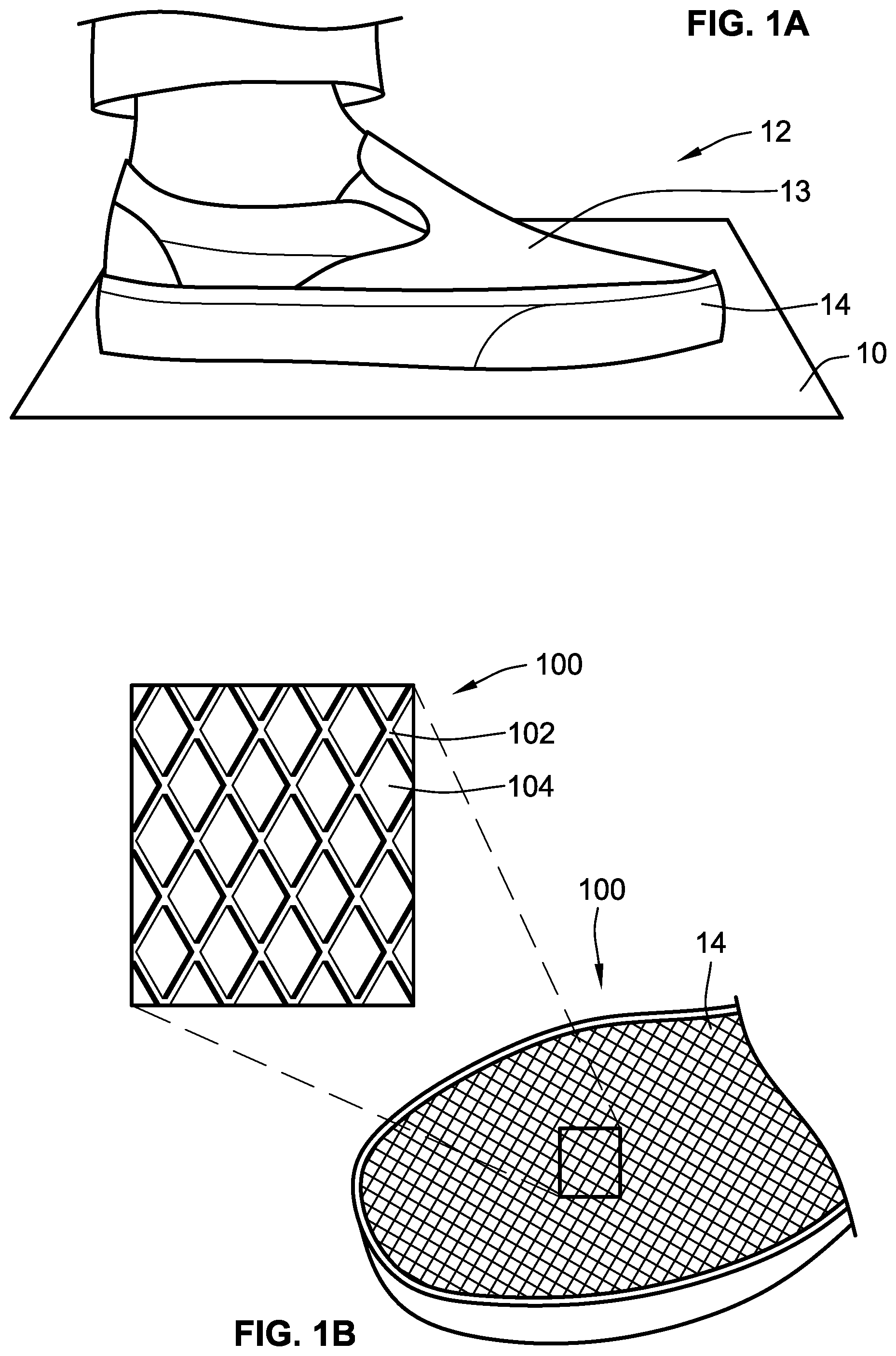
[0008] FIG. 1A is a perspective view of a shoe contacting a surface in a flat configuration, according to aspects of the present disclosure;
[0009] FIG. 1B is a perspective view of a sheet of material on the underside of the shoe of FIG. 1A when the sheet of material is in a first orientation, according to aspects of the present disclosure;
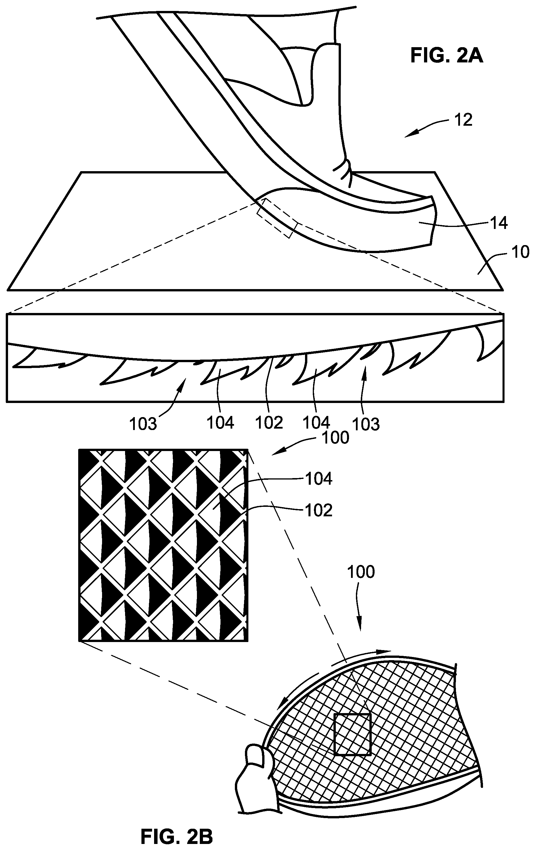
[0010] FIG. 2A is a perspective view of the shoe of FIG. 1A contacting the surface in a flexed configuration, according to aspects of the present disclosure;
[0011] FIG. 2B is a perspective view of the sheet of material on the underside of the shoe of FIG. 2A when the sheet of material is in a second orientation, according to aspects of the present disclosure;
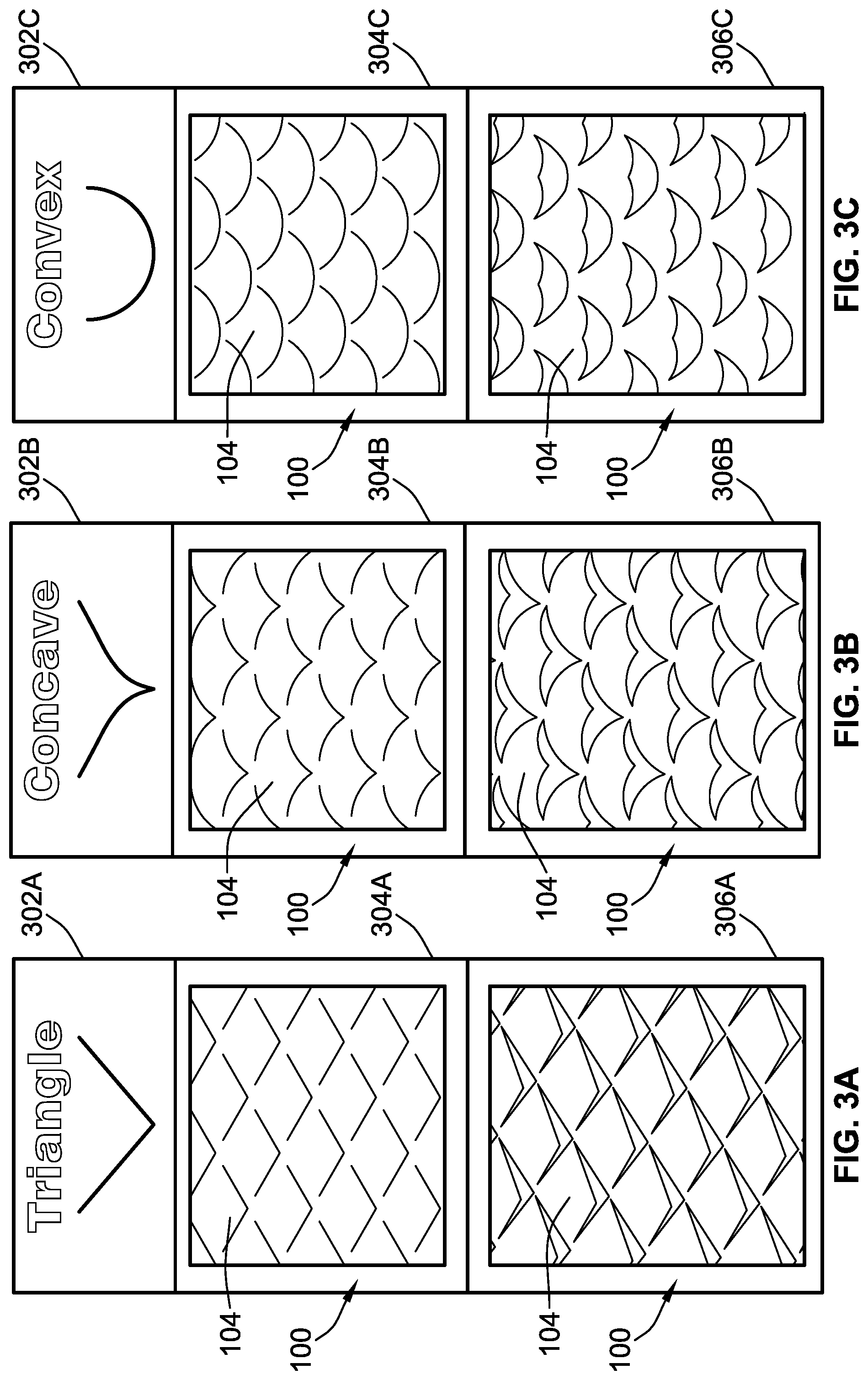
[0012] FIG. 3A shows the material of FIG. 1B and FIG. 2B with movable projections having a triangular shape, according to aspects of the present disclosure;
[0013] FIG. 3B shows the material of FIG. 1B and FIG. 2B with movable projections having a concave shape, according to aspects of the present disclosure;
[0014] FIG. 3C shows the material of FIG. 1B and FIG. 2B with movable projections having a convex shape, according to aspects of the present disclosure;
[0015] FIG. 3D shows the material of FIG. 1B and FIG. 2B with movable projections having a rectangular shape, according to aspects of the present disclosure;
[0016] FIG. 3E shows the material of FIG. 1B and FIG. 2B with movable projections having a barbed shape, according to aspects of the present disclosure;
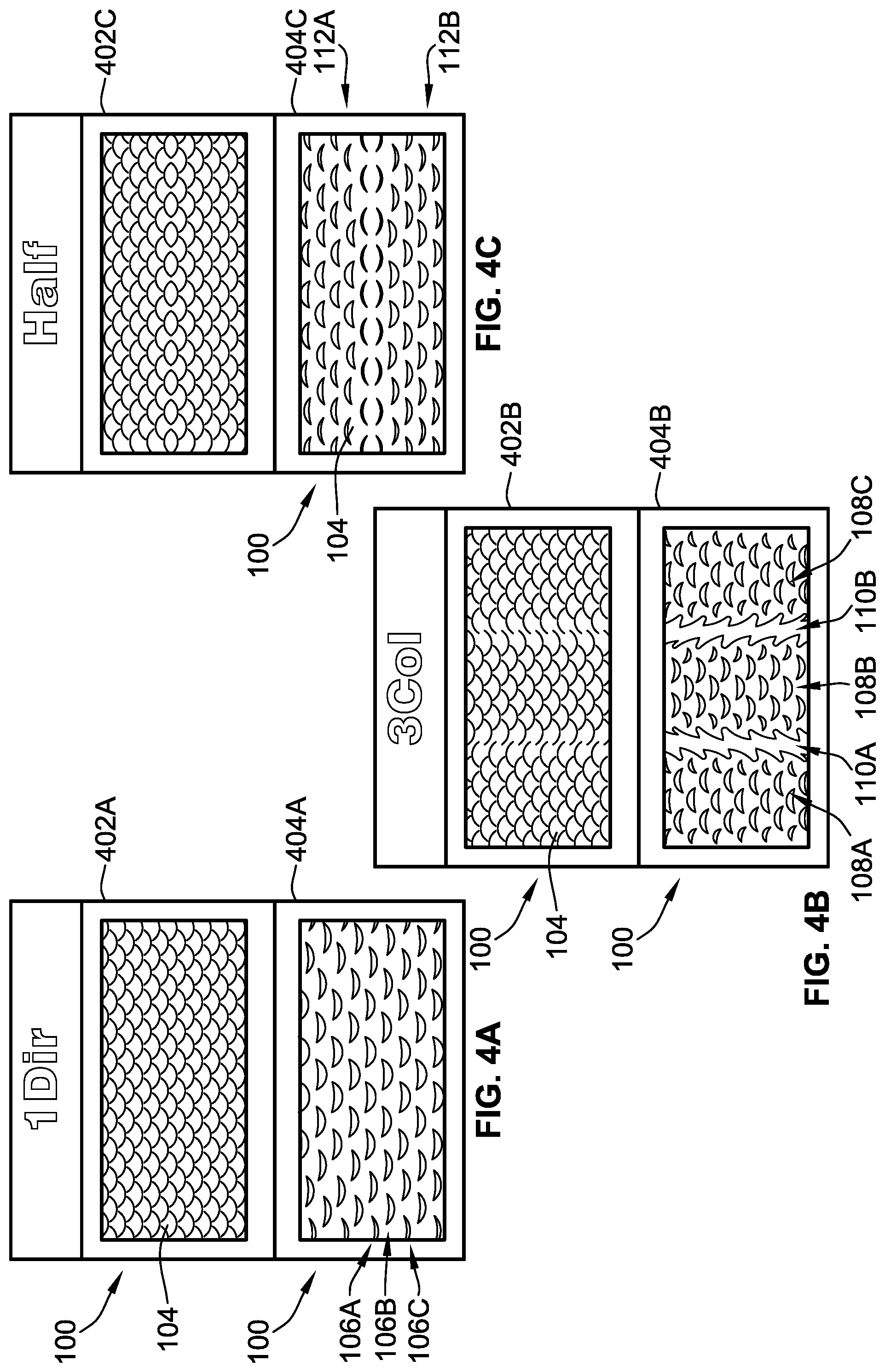
[0017] FIG. 4A shows the movable projections of FIG. 3C arranged in a one-direction pattern, according to aspects of the present disclosure;
[0018] FIG. 4B shows the movable projections of FIG. 3C arranged in a three-column pattern, according to aspects of the present disclosure;
[0019] FIG. 4C shows the movable projections of FIG. 3C arranged in a half pattern, according to aspects of the present disclosure;
[0020] FIG. 4D shows the movable projections of FIG. 3C arranged in a 16.times.2 pattern, according to aspects of the present disclosure;
[0021] FIG. 4E shows the movable projections of FIG. 3C arranged in a checkerboard pattern, according to aspects of the present disclosure;
[0022] FIG. 5 is a plot measuring imparted force versus displacement for the sheet of material of FIG. 1B and FIG. 2B, according to aspects of the present disclosure;
[0023] FIG. 6 is a plot comparing the static and kinetic coefficients of friction for sheets of material having movable projections arranged in the patterns of FIGS. 4A-4E, according to aspects of the present disclosure; and
[0024] FIG. 7 is a plot comparing the static and kinetic coefficients of friction for sheets of material having movable projections with the shapes of FIGS. 3A-3E, according to aspects of the present disclosure.
[0025] The present disclosure is susceptible to various modifications and alternative forms. Some representative embodiments have been shown by way of example in the drawings and will be described in detail herein. It should be understood, however, that the invention is not intended to be limited to the particular forms disclosed. Rather, the disclosure is to cover all modifications, equivalents, and alternatives falling within the spirit and scope of the invention as defined by the appended claims.
DETAILED DESCRIPTION
[0026] The present inventions can be embodied in many different forms. Representative embodiments are shown in the drawings, and will herein be described in detail. The present disclosure is an example or illustration of the principles of the present disclosure, and is not intended to limit the broad aspects of the disclosure to the embodiments illustrated. To that extent, elements, and limitations that are disclosed, for example, in the Abstract, Summary, and Detailed Description sections, but not explicitly set forth in the claims, should not be incorporated into the claims, singly or collectively, by implication, inference, or otherwise. For purposes of the present detailed description, unless specifically disclaimed, the singular includes the plural and vice versa; and the word "including" means "including without limitation." Moreover, words of approximation, such as "about," "almost," "substantially," "approximately," and the like, can be used herein to mean "at," "near," or "nearly at," or "within 3-5% of," or "within acceptable manufacturing tolerances," or any logical combination thereof, for example.
[0027] FIG. 1A shows a shoe 12 standing on a surface 10 in a flat configuration. The surface 10 can be a floor, the ground, or any other surface that a person wearing a shoe may be standing on. The shoe 12 has an upper portion 13 and a sole 14 attached to the upper portion 13. The upper portion 13 is configured to receive a foot of a user wearing the shoe. In FIG. 1A, the shoe 12 is in a flat configuration on the surface 10. FIG. 1B shows a material 100 coupled to the sole 14 that can be used to adjust the amount of friction between the shoe 12 and the surface 10. The material 100 is formed from a substrate 102 and a plurality of movable projections 104. In the illustrated implementation, the substrate 102 includes a number of cuts or apertures. The material leftover forms the movable projections 104. Thus, the movable projections are integrally formed with the substrate 102. However, in other implementations, the movable projections 104 can be separate components that are coupled to the substrate 102. In some implementations, the movable projections 104 are formed on a first side of the substrate 102, and an opposing second side of the substrate 102 includes an adhesive material that can be used to adhere the material 100 to the sole 14 of the shoe 12. The adhesive material can be covered by a temporary layer. Thus, attaching the substrate 102 to the sole 14 of the user's shoe 12 can be achieved by removing the temporary layer to reveal the adhesive material, and then pressing the side of the substrate 102 with the adhesive material to the sole 14. In some implementations, the substrate 102 can be shaped to fit the sole 14 (for example, by cutting the desired shape out of a larger piece of material) before or after attaching the substrate 102 to the sole 14.
[0028] FIG. 1A shows the shoe 12 in a generally flat configuration with little to no curvature. As shown in FIG. 1B, because the material 100 can be attached to the sole 14 of the shoe 12, the substrate 102 also has a generally flat configuration with little to no curvature. When the substrate 102 is in the generally flat configuration, the movable projections 104 are in a first orientation relative to the substrate 102. In the first orientation, the movable projections 104 are generally coplanar with the substrate 102. As can be seen in the zoomed-in inset view of FIG. 1B, the movable projections 104 can occupy a substantial portion of the surface area of the material 100, such that the substrate 102 exists only in the small areas of the material 100 between the movable projections 104.
[0029] When the substrate 102 is in the flat configuration and the movable projections 104 are in their first orientation where they are coplanar with the substrate 102, the substrate 102 and the movable projections 104 form a generally flat contact area between the surface 10 and the material 100. This flat contact area provides a certain coefficient of friction between the surface 10 and the shoe 12/the material 100.
[0030] FIG. 2A shows the shoe 12 in a flexed and/or stretched configuration during the user's stride. Specifically, FIG. 2A illustrates the position of the shoe 12 during the portion of the user's stride when the user is pushing forward (e.g., to the right relative to the plane of FIG. 2A) off of the shoe 12, and thus exerting a backwards force (e.g., a force directed to the left relative to the plane of FIG. 2A) on the shoe 12. FIG. 2B shows the substrate 102 of the material 100 in the flexed and/or stretched configuration. In their flexed configurations, the shoe 12 and the substrate 102 have a larger curvature than in their generally flat configurations. Because the material 100 is coupled to the sole 14 of the shoe 12, the substrate 102 moves to its flexed configuration as the shoe 12 moves to its flexed configuration as the user wearing the shoe 12 walks on the surface 10. When the substrate 102 moves to the flexed configuration, the movable projections 104 move from their first orientation relative to the substrate 102 (FIG. 1B) to a second orientation relative to the substrate 102.
[0031] The zoomed-in inset view of FIG. 2A shows that the movable projections 104 are formed from a plurality of cuts or openings defined in the substrate 102. Because of these cuts, as the substrate 102 flexes and moves to the second configuration, the movable projections 104 form a series of spikes that pop out of or buckle up from the substrate 102 to the second orientation, with gaps 103 separating adjacent ones of the movable projections 104. Thus, in the illustrated implementations, the material 100 can be initially formed as a single sheet that forms the substrate 102, with no cuts or openings defined in the sheet. Then, the cuts or openings can be formed in the sheet of material 100. The portions of the sheet of material 100 that pop out or buckle up will form the movable projections 104, while the remaining portions of the sheet of material 100 that do not pop out or buckle up will form the substrate 102.
[0032] As can be seen in the zoomed-in inset views of both FIG. 2A and FIG. 2B, when the movable projections 104 are in the second orientation, the movable projections 104 extend from the substrate 102 at an angle relative to the substrate 102. Generally, this angle can be any angle that is greater than about degrees and less than or equal to about 90 degrees. Thus, when in the second orientation, the movable projections 104 extend both away from the substrate 102 (e.g., normal to the substrate 102), and in a direction along the substrate 102 itself (e.g., along the sole 14 of the shoe 12). As can be seen in the zoomed-in inset view of FIG. 2B, the movable projections 104 are shown extending leftward relative to the plane of FIG. 2B, which is backwards along the sole 14 toward the heel of the shoe 12. However, in other implementations, the movable projections 104 can extend in different directions or combinations of directions along the substrate 102 (e.g., different directions along the sole 14 of the shoe 12).
[0033] When the substrate 102 is in the flexed configuration and the movable projections 104 have moved to their second orientation where they extend away from the substrate 102, the substrate 102 and the movable projections 104 form a generally rough contact area between the surface 10 and the material 100. This rough contact area provides a coefficient of friction between the surface 10 and the shoe 12/the material 100 that is greater than the coefficient present when the movable projections 104 are in their first orientation.
[0034] Thus, as the user walks in the shoes 12 with the material 100 adhered on the soles 14, the movable projections 104 move between the first orientation (coplanar with the substrate 102) and the second orientation (extending away from the substrate 102). As shown in FIG. 2B, when the movable projections 104 are in the second orientation, the movable projections 104 can dig in to the surface 10, thereby increasing the coefficient of friction between the surface 10 and the shoe 12/the material 100. When the user pushes off of the shoe 12 and exerts a backward force on the shoe 12, the movable projections 104 being in the second orientation (e.g., extending both away from the sole 14 and generally backwards along the sole 14) increases the amount of friction between the user's shoes 12 and the surface 10 to be increased, which in turn decreases the chance that the user will slip, trip, fall, etc. The material 100 can be used on a variety of different surfaces, such as hardwood floor, vinyl, concrete, asphalt, gravel, oily or wet surfaces, etc. Because the movable projections 104 are configured to move to the second orientation as the user is walking and the user's shoe 12 moves to the flex configuration, no additional energy source is needed to increase the friction between the user's shoe 12 and the object or surface on which the user is walking.
[0035] Referring now to FIGS. 3A-3E, the movable projections 104 can be formed in a variety of different shapes. FIG. 3A includes boxes 302A, 304A, and 306A that show the material 100 when the movable projections 104 have a triangular shape. The upper box 302A shows an outline of the cut in the material 100 that forms each of the movable projections 104. As shown, the cut has a triangular shape that includes two generally straight edges meeting at a point. The upper box 302A thus shows the triangular leading edge of each of the movable projections 104. The middle box 304A shows the material 100 when the substrate is in the generally flat configuration, for example when the material 100 is adhered to the user's shoe and the shoe is flat on the ground while the user walks. In the generally flat configuration, while the triangular outline of the cut that forms movable projections 104 is visible, the movable projections 104 do not extend from the substrate, and thus the material 100 forms a generally flat contact surface. The lower box 306A shows the material 100 when the substrate is in the generally flexed configuration, for example when the material 100 is adhered to the user's shoe and the shoe is flexed while the user walks. In the generally flexed configuration, the triangular movable projections 104 begin to fold in half and extend away from the substrate, thereby increasing the coefficient of friction between the shoe and the ground, and thus the amount of friction between the shoe and the ground.
[0036] FIG. 3B includes boxes 302B, 304B, and 306B that show the material 100 when the movable projections 104 have a concave shape. The upper box 302B shows an outline of the cut in the material 100 that forms each of the movable projections 104. As shown, the cut has a generally concave shape. The concave shape is similar to the triangular shape in box 302A, and includes two edges meeting at a point. However, the edges are not straight, but instead curve upward and outward (with respect to the plane of FIG. 3), such that the shape has a degree of concavity. The upper box 302B thus shows the concave-shaped leading edge of each of the movable projections 104. The middle box 304B shows the material 100 when the substrate is in the generally flat configuration, for example when the material 100 is adhered to the user's shoe and the shoe is flat on the ground while the user walks. In the generally flat configuration, while the concave outline of the cut that forms movable projections 104 is visible, the movable projections 104 do not extend from the substrate, and thus the material 100 forms a generally flat contact surface. The lower box 306B shows the material 100 when the substrate is in the generally flexed configuration, for example when the material 100 is adhered to the user's shoe and the shoe is flexed while the user walks. In the generally flexed configuration, the concave-shaped movable projections 104 begin to fold in half and extend away from the substrate, thereby increasing the coefficient of friction between the shoe and the ground, and thus the amount of friction between the shoe and the ground.
[0037] FIG. 3C includes boxes 302C, 304C, and 306C that show the material 100 when the movable projections 104 have a convex shape. The upper box 302C shows an outline of the cut in the material 100 that forms each of the movable projections 104. As shown, the convex shape is a generally half-circle shape. The upper box 302C thus shows the convex-shaped leading edge of each of the movable projections 104. The middle box 304C shows the material 100 when the substrate is in the generally flat configuration, for example when the material 100 is adhered to the user's shoe and the shoe is flat on the ground while the user walks. In the generally flat configuration, while the concave outline of the cut that forms movable projections 104 is visible, the movable projections 104 do not extend from the substrate, and thus the material 100 forms a generally flat contact surface. The lower box 306C shows the material 100 when the substrate is in the generally flexed configuration, for example when the material 100 is adhered to the user's shoe and the shoe is flexed while the user walks. In the generally flexed configuration, the convex-shaped movable projections 104 begin to fold in half and extend away from the substrate, thereby increasing the coefficient of friction between the shoe and the ground, and thus the amount of friction between the shoe and the ground.
[0038] FIG. 3D includes boxes 302D, 304D, and 306D that show the material 100 when the movable projections 104 have a rectangular shape. The upper box 302D shows an outline of the cut in the material 100 that forms each of the movable projections 104. As shown, the rectangular shape is formed by a front edge and two side edges extending generally perpendicularly from the front edge. The upper box 302D thus shows the rectangular leading edge of each of the movable projections 104. The middle box 304D shows the material 100 when the substrate is in the generally flat configuration, for example when the material 100 is adhered to the user's shoe and the shoe is flat on the ground while the user walks. In the generally flat configuration, while the rectangular outline of the cut that forms movable projections 104 is visible, the movable projections 104 do not extend from the substrate, and thus the material 100 forms a generally flat contact surface. The lower box 306D shows the material 100 when the substrate is in the generally flexed configuration, for example when the material 100 is adhered to the user's shoe and the shoe is flexed while the user walks. In the generally flexed configuration, the rectangular movable projections 104 begin to fold in half and extend away from the substrate, thereby increasing the coefficient of friction between the shoe and the ground, and thus the amount of friction between the shoe and the ground.
[0039] FIG. 3E includes boxes 302E, 304E, and 306E that show the material 100 when the movable projections 104 have a barbed shape. The upper box 302E shows an outline of the cut in the material 100 that forms each of the movable projections 104. As shown, the barbed shape is similar to the triangle shape or the concave shape, and includes two edges that meet at a point. However, the two edges include a plurality of barbs or points, such that the movable projections 104 appear to have a wavy shape. The upper box 302E thus shows the barb-shaped leading edge of each of the movable projections 104. The middle box 304E shows the material 100 when the substrate is in the generally flat configuration, for example when the material 100 is adhered to the user's shoe and the shoe is flat on the ground while the user walks. In the generally flat configuration, while the barb-shaped outline of the cut that forms movable projections 104 is visible, the movable projections 104 do not extend from the substrate, and thus the material 100 forms a generally flat contact surface. The lower box 306E shows the material 100 when the substrate is in the generally flexed configuration, for example when the material 100 is adhered to the user's shoe and the shoe is flexed while the user walks. In the generally flexed configuration, the barb-shaped movable projections 104 begin to fold in half and extend away from the substrate, thereby increasing the coefficient of friction between the shoe and the ground, and thus the amount of friction between the shoe and the ground.
[0040] Referring now to FIGS. 4A-4E, the movable projections 104 can also be formed in a variety of different patterns. In some implementations, the movable projections 104 are formed from a periodic array of cuts. Each period of the array can include a certain pattern of cuts that is repeated across all of the material 100. In some implementations, the periodic array might include multiple levels of periodicity. For example, a smaller pattern of cuts may be repeated across a subset of the material 100, and this smaller pattern may be part of a larger pattern that is repeated across all of the material 100.
[0041] FIG. 4A includes boxes 402A and 404A that illustrate the movable projections 104 being arranged in a pattern referred to as "1Dir" or "one direction." Box 402A shows the movable projections 104 when the material 100 is in the generally flat configuration, and box 404A shows the movable projections 104 when the material 100 is in the generally flexed configuration. As can be seen, the movable projections 104 are arranged into a plurality of offset rows. The rows are offset from each other, such that a movable projection 104 in any one row is not directly aligned with any of the movable projections 104 in both the row above, or the row below. For explanatory purposes, a first row 106A, a second row 106B, and a third row 106C are identified in box 404A. The second row 106B is positioned between the first row 106A and the third row 106C. As can be seen, each movable projection 104 in the first row 106A is aligned with a corresponding movable projection 104 in the third row 106C. However, none of the movable projections 104 in the second row 106B are aligned with any corresponding movable projections 104 in either the first row 106A or the third row 106C. Instead, each movable projection 104 in the second row is aligned with the movable projections 104 in a fourth row 106D that is positioned immediately next to the third row 106C.
[0042] In some implementations, each row includes a single line of movable projections 104 that all extend in an identical direction along the substrate, when the movable projections 104 are in the second orientation. For example, box 404A shows all of the movable projections 104 extending away from the substrate and downward relative to the plane of FIG. 4A. However, in other implementations, different movable projections 104 within the same row could extend in different directions. In further implementations, the movable projections 104 within the same row all extend in the same direction relative to the substrate, but different rows of movable projections 104 could extend in different directions. And in still further implementations, each row of movable projections 104 could include multiple lines of movable projections 104. In these implementations, each row of movable projections 104 could include smaller sub-rows of movable projections 104 that are aligned with each other. Moreover, the rows of movable projections 104 can themselves extend in any direction relative to the object that the material 100 is adhered to. For example, when the material 100 is adhered to the sole of a shoe, the rows of movable projections 104 could extend along the length of the sole between the heel and the toe; along the width of the sole between the inner portion of the sole and the outer portion of the sole; or generally diagonally along both the length and the width of the sole.
[0043] Referring now to FIG. 4B, the pattern of offset rows illustrated in FIG. 4B can be part of a larger pattern of movable projections 104. FIG. 4B includes boxes 402B and 404B that illustrate the movable projections 104 being arranged in a pattern referred to as "3Col" or "three column." Box 402B shows the movable projections 104 when the material 100 is in the generally flat configuration, and box 404B shows the movable projections 104 when the material 100 is in the generally flexed configuration. In the 3Col arrangement, the movable projections 104 are arranged in three different groups 108A, 108B, and 108C. In the illustrated implementation, the groups 108A, 108B, and 108C extend along the surface of the material 100 and are generally parallel to each other. In that manner, the groups 108A, 108B, and 108C form three columns that are vertical relative to the plane of FIG. 4B. The movable projections 104 within each of the three groups 108A, 108B, and 108C are arranged in 1Dir pattern shown in FIG. 4A, where one row of movable projections 104 is offset from the rows of movable projections 104 immediately adjacent to the one row on either side. However, the movable projections 104 within each group 108A, 108B, 108C could be arranged in other patterns as well.
[0044] The movable projections 104 in the first group 108A and the third group 108C all extend or point in the same direction (shown as upward relative to the plane of FIG. 4B), while the movable projections 104 in the second group 108B extend opposite from the first group 108A and the third group 108C (shown as downward relative to the plane of FIG. 4B). However, in other implementations, the movable projections 104 in all three groups 108A, 108B, 108C could extend in the same direction, different directions (e.g. upward, downward, and sideways relative to the plane of FIG. 4B), or any combination of directions. If the material 100 is adhered to the sole of a shoe, the groups 108A, 108B, and 108C could extend along the length of the sole of the shoe, the width of the sole of the shoe, or generally along both the length and the width of the sole of the shoe. Moreover, in this implementation, the movable projections 104 could be arranged into only two separate groups of movable projections, or four or more groups of movable projections.
[0045] As can be seen by comparing box 404A and 404B, the cuts in the material 100 that form the movable projections 104 are such that when the movable projections 104 extend from the substrate in the second orientation, gaps 110A and 110B are formed between each of the groups 108A, 108B, 108C. In some implementations, the gaps 110A, 110B may be formed by portions of the substrate that have no movable projections. In other implementations, the gaps may be formed by portions of the object to which the material 100 is adhered (e.g., a shoe sole).
[0046] Moreover, similar to the pattern in FIG. 4A, the rows of movable projections 104 can themselves extend in any direction relative to the object that the material 100 is adhered to. For example, when the material 100 is adhered to the sole of a shoe, the groups 108A, 108B, and 108C of movable projections 104 could extend along the length of the sole between the heel and the toe; along the width of the sole between the inner portion of the sole and the outer portion of the sole; or generally diagonally along both the length and the width of the sole.
[0047] It is further noted that FIG. 4B shows the movable projections 104 extending generally along the same axis on which the groups 108A, 108B, and 108C extend (e.g., the movable projections 104 extend either upward or downward relative to the plane of FIG. 4B when in the second orientation, and the groups 108A, 108B, and 108C also extend upward and downward relative to the plane of FIG. 4B). However, in other implementations, the movable projections 104 could extend in a different direction when in the second orientation, as compared to the direction along which the groups 108A, 108B, and 108C extend.
[0048] Referring now to FIG. 4C, boxes 402C and 404C illustrate the movable projections 104 arranged in a pattern referred to as "Half." Box 402C shows the movable projections 104 when the material 100 is in the generally flat configuration, and box 404C shows the movable projections 104 when the material 100 is in the generally flexed configuration. In this pattern, the movable projections 104 are arranged into two separate groups 112A and 112B. Similar to the 3Col pattern, the movable projections 104 within each group 112A, 112B are arranged using the offset row arrangement of the 1Dir pattern. The movable projections 104 in group 112A all extend or point upward relative to the plane of FIG. 4C, while the movable projections in group 112B all extend or point downward relative to the plane of FIG. 4C. In other implementations however, the movable projections 104 in groups 112A and 112B could extend in the same direction, or even in directions perpendicular to each other.
[0049] In the "Half" arrangement, the cuts in the material 100 that form the movable projections 104 are such that when the movable projections 104 extend from the substrate in the second orientation, there are generally no gaps formed between the two groups 112A and 112B, whether the gaps are formed from portions of the substrate with no movable projections 104, or from portions of the sole of the shoe. Instead, the row at the end of group 112A (the bottom relative to the plane of FIG. 4C) and the row at the end of group 112B (the top relative to the plane of FIG. 4C) together form a single row that includes a plurality of pairs of movable projections 104. Each pair of movable projections 104 includes a first movable projection that extends in the same direction as the rest of group 112A when in the second orientation, and a second movable projection that extends in the same direction as the rest of group 112B when in the second orientation.
[0050] Similar to the patterns in FIGS. 4A-4B, the groups 112A, 112B of movable projections 104 can extend in any direction relative to the objection that the material 100 is adhered to. For example, when the material 100 is adhered to the sole of a shoe, the groups 110A, 110B of movable projections 104 could extend along the length of the sole between the heel and the toe; along the width of the sole between the inner portion of the sole and the outer portion of the sole; or generally diagonally along both the length and the width of the sole. Moreover, the individual offset rows of movable projections 104 can also extend in any direction relative to the object that the material 100 is adhered to, e.g., along the length of the sole, along the width of the sole, or along both the length of the sole and the width of the sole.
[0051] Referring now to FIG. 4D, boxes 402D and 404D illustrate the movable projections 104 arranged in a pattern referred to as "16.times.2." Box 402D shows the movable projections 104 when the material 100 is in the generally flat configuration, and box 404D shows the movable projections 104 when the material 100 is in the generally flexed configuration. In this arrangement, the movable projections 104 are arranged in a plurality of offset rows, similar to the 1Dir pattern in FIG. 4A. However, instead of every row of movable projections 104 extending or pointing in the same direction along the substrate when the movable projections 104 are in the second orientation, this pattern alternates the direction in which the movable projections 104 extend or point every two rows. Thus, for a first row 114A of movable projections 104, the movable projections 104 in a second adjacent row 114B will extend in the same direction as the movable projections 104 in the first row 114A, while the movable projections 104 in a third row 114C that is adjacent to the second row 114B (e.g., the second row 114B is disposed between the first row 114A and the third row 114C) will extend in the opposite direction from the movable projections 104 in the first row 114A. This pattern of movable projections 104 maintains the offset row arrangement however. Thus, the movable projections 104 in the second row 114B (e.g., the middle row) will not be aligned with any corresponding movable projections 104 in the first row 114A or the third row 114C, while each movable projection 104 in the first row 114A will be aligned with a corresponding movable projection 104 in the third row 114C, even though the movable projections 104 will be extending in opposite directions.
[0052] Similar to the patterns in FIGS. 4A-4C, the individual rows of movable projections 104 can extend in any direction relative to the objection that the material 100 is adhered to. For example, when the material 100 is adhered to the sole of a shoe, the groups 110A, 110B of movable projections 104 could extend along the length of the sole between the heel and the toe; along the width of the sole between the inner portion of the sole and the outer portion of the sole; or generally diagonally along both the length and the width of the sole.
[0053] Referring now to FIG. 4E, boxes 402E and 404E illustrate the movable projections 104 arranged in a pattern referred to as "Checker" or "Checkerboard." Box 402E shows the movable projections 104 when the material 100 is in the generally flat configuration, and box 404E shows the movable projections 104 when the material 100 is in the generally flexed configuration. In this pattern, the movable projections 104 are generally arranged into four groups: a first group 116A (upper-left relative to the plane of FIG. 4E), a second group 116B (lower-left relative to the plane of FIG. 4E), a third group 116C (lower-right relative to the plane of FIG. 4E), and a fourth group 116D (upper-right relative to the plane of FIG. 4E). As can be seen in FIG. 4E, these four groups 116A-116D of movable projections are arranged in a generally square or generally rectangular shape.
[0054] The second group 116B is positioned adjacent to and spaced apart from the first group 116A along a first axis 118A that extends vertically relative to the plane of FIG. 4E. Similarly, the third group 116C is positioned adjacent to and spaced apart from the fourth group 116D along the first axis 118A. The fourth group 116D is positioned adjacent to and spaced apart from the first group 116A along a second axis 118B that extends horizontally relative to the plane of FIG. 4E. Similarly, the third group 116C is positioned adjacent to and spaced apart from the second group 116B along the second axis 118B. Thus, the four groups 116A-116D generally form the four quadrants of a square or rectangle.
[0055] When the movable projections 104 of the first group 116A are in the second orientation, they extend along the substrate in a first direction along the first axis 118A. Relative to the plane of FIG. 4E, the first direction is downward. When the movable projections 104 of the second group 116B are in the second orientation, they extend along the substrate in a second direction along the first axis 118A. Relative to the plane of FIG. 4E, the second direction is upward. When the movable projections 104 of the third group 116C are in the second orientation, they extend along the substrate in the first direction along the first axis 118A. When the movable projections 104 of the fourth group 116D are in the second orientation, they extend along the substrate in the second direction along the first axis 118A. Moreover, within each group 116A-116D, the movable projections 104 are arranged in the offset row pattern that is also illustrated in FIGS. 4A-4D.
[0056] As can be seen by comparing box 404E and 404E, the cuts in the material 100 that form the movable projections 104 are such that when the movable projections 104 extend from the substrate in the second orientation, a gap 120 is formed that separates the first group 116A and the second group 116B from the third group 116C and the fourth group 116D. In some implementations, the gap 120 may be formed from a portion of the substrate that has no movable projections. In other implementations, the gap 120 may be formed by portions of the object to which the material 100 is adhered (e.g., a shoe sole). In some implementations, all of the material 100 includes only the four groups 116A-116D. Thus, the entire surface area of the material 100 can comprise only the four groups 116A-116D. However, in other implementations, the four groups 116A-116D of movable projections 104 are part of a larger periodic array of movable projections 104, where each period includes one of the first group 116A, one of the second group 116B, one of the third group 116C, and one of the fourth group 116D.
[0057] The material 100 can be formed using a variety of different materials and techniques. In some implementations, the material 100 is formed from polyester plastic and fabricated using laser cutting techniques. In some of these implementations using polyester plastic, the polyester plastic material has a thickness of about 0.005 inches and a tensile strength of about 30,000 pounds per square inch (PSI). In further implementations, the material 100 is formed from spring steel (such as blue tempered AISI 1095) and fabricated using laser cutting techniques. In some of these implementations using spring streel, the spring steel material has a thickness of about 0.002 inches, a Rockwell hardness of C50, and a tensile strength of about 238,000 PSI. In additional implementations, the material 100 is formed from a polyester film, such as a film formed from polyethylene terephthalate (PET), and fabricated using laser cutting techniques. In some of these implementations using PET, the polyester film has a thickness of about 0.007 inches, and a tensile strength of about 28,000 PSI. In other implementations, the material 100 is formed from polytetrafluoroethylene (PTFE, also referred to as Teflon.RTM.) and fabricated using laser cutting techniques. In some of these implementations using PTFE, the PTFE material has a thickness of about 0.01 inches, a Rockwell hardness of R60, and a tensile strength of about 4,500 PSI.
[0058] In further implementations, the material 100 is formed from a silicone-based rubber having a Shore A hardness value of 8, and fabricated using casting techniques. In some of these implementations, the silicone-based rubber material has a thickness of about 0.05 inches and a tensile strength of about 300 PSI. In additional implementations, the material 100 is formed from a silicone-based rubber having a Shore A hardness value of 22, and fabricated using casting techniques. In some of these implementations, the silicone-based rubber material has a thickness of about 0.05 inches and a tensile strength of about 400 PSI. In other implementations, the material 100 is formed from a silicone-based rubber having a Shore A hardness value of 32, and fabricated using casting techniques. In some of these implementations, the silicone-based rubber material has a thickness of about 0.05 inches and a tensile strength of about 400 PSI. Thus, the material 100 can have a thickness of between about 0.002 inches and about 0.05 inches.
[0059] FIG. 5 shows a plot 500 that measures imparted force versus the displacement of a testing sled containing a sheet of the material 100. The sheet of the material 100 can be stretched across the testing sled such that the movable projections move to their second orientation. The testing sled can be placed onto a surface such that the material 100 contacts the surface. A known mass (such as a 5 kg mass) can be placed on top of the testing sled, and the testing sled can be pulled at a constant velocity (such as 10 millimeters per second). The force imparted on the testing sled is then measured as a function of the displacement of the testing sled (e.g., the distance traveled), with the outcome being shown as plot 600.
[0060] Plot 500 thus illustrates the friction response of a sheet of the material 100 on a surface. Force line 502 on plot 500 illustrates the static friction force, which is the amount of imparted force required to overcome the static friction between the sheet of material 100 and the surface onto which it rests. The coefficient of static friction can then be determined by taking the ratio of the static friction force to the normal force, which is equal to the weight of the known mass placed onto the testing sled. The kinetic friction force can be determined by taking the average imparted force after the testing sled begins to move. In plot 500, the kinetic friction force is shown by force line 504. The coefficient of kinetic friction can then be determined by taking the ratio of the kinetic friction force to the normal force.
[0061] FIG. 6 shows a plot 600 that compares the static and kinetic coefficients of friction obtained using the testing scheme discussed above with respect to FIG. 5, for sheets of the material 100 having different patterns of movable projections. The testing done to obtain plot 600 used a sheet of material with concave-shaped movable projections made from polyester plastic. The sheet of material was tested on an icy surface. Bar 602A shows the static coefficient of friction for movable projections arranged in the 1Dir pattern, while bar 602B shows the kinetic coefficient of friction for movable projections arranged in the 1Dir pattern. Bar 604A shows the static coefficient of friction for movable projections arranged in the 3Col pattern, while bar 604B shows the kinetic coefficient of friction for movable projections arranged in the 3Col pattern. Bar 606A shows the static coefficient of friction for movable projections arranged in the 16.times.2 pattern, while bar 606B shows the kinetic coefficient of friction for movable projections arranged in the 16.times.2 pattern.
[0062] Bar 608A shows the static coefficient of friction for movable projections arranged in the Half pattern, while bar 608B shows the kinetic coefficient of friction for movable projections arranged in the Half pattern. Bar 610A shows the static coefficient of friction for movable projections arranged in the Checker pattern, while bar 610B shows the kinetic coefficient of friction for movable projections arranged in the Checker pattern. Finally, bar 612A shows the static coefficient of friction for a control with no movable projections, while bar 612B shows the kinetic coefficient of friction for a control with no movable projections.
[0063] Plot 600 illustrates that the presence of the movable projections in the second orientation increased the friction on the icy surface relative to the control, regardless of which pattern of movable projections was used. The 16.times.2 pattern resulted in the largest static coefficient of friction, while the 3Col pattern resulted in the largest kinetic coefficient of friction.
[0064] FIG. 7 shows a plot 700 that compares the static and kinetic coefficients of friction obtained using the scheme discuss above with respect to FIG. 5, for sheets of the material 100 having movable projections with different shapes. The testing done to obtain plot 700 used a sheet of material with movable projections made from plastic polyester and arranged in the 16.times.2 pattern. The sheet of material was tested on an icy surface. Bar 702A shows the static coefficient of friction for concave-shaped movable projections, while bar 702B shows the kinetic coefficient of friction for the concave-shaped movable projections. Bar 704A shows the static coefficient of friction for convex-shaped movable projections, while bar 704B shows the kinetic coefficient of friction for the convex-shaped movable projections. Bar 706A shows the static coefficient of friction for rectangular movable projections, while bar 706B shows the kinetic coefficient of friction for the rectangular movable projections.
[0065] Bar 708A shows the static coefficient of friction for triangular movable projections, while bar 708B shows the kinetic coefficient of friction for the triangular movable projections. Bar 710A shows the static coefficient of friction for barbed-shape movable projections, while bar 710B shows the kinetic coefficient of friction for the barbed-shape movable projections. Finally, bar 712A shows the static coefficient of friction for a control with no movable projections, while bar 712B shows the kinetic coefficient of friction for a control with no movable projections.
[0066] Plot 700 illustrates that the presence of the movable projections in the second orientation increased the friction on the icy surface relative to the control, regardless of what the shape of the movable projections is. The triangular movable projections resulted in the largest static and kinetic coefficients of friction, thus demonstrating the greatest friction increase relative to the control. Thus, in some implementations, the material 100 can have triangular movable projections that are arranged in the 3Col pattern or the 16.times.2 pattern.
[0067] The terminology used herein is for the purpose of describing particular embodiments only, and is not intended to be limiting of the invention. As used herein, the singular forms "a," "an," and "the" are intended to include the plural forms as well, unless the context clearly indicates otherwise. Furthermore, to the extent that the terms "including," "includes," "having," "has," "with," or variants thereof, are used in either the detailed description and/or the claims, such terms are intended to be inclusive in a manner similar to the term "comprising."
[0068] Unless otherwise defined, all terms (including technical and scientific terms) used herein have the same meaning as commonly understood by one of ordinary skill in the art. Furthermore, terms, such as those defined in commonly used dictionaries, should be interpreted as having a meaning that is consistent with their meaning in the context of the relevant art, and will not be interpreted in an idealized or overly formal sense unless expressly so defined herein.
[0069] One or more elements or aspects or steps, or any portion(s) thereof, from one or more of any of claims 1-52 below can be combined with one or more elements or aspects or steps, or any portion(s) thereof, from one or more of any of the other claims 1-52 or combinations thereof, to form one or more additional implementations and/or claims of the present disclosure.
[0070] While various embodiments of the present invention have been described above, it should be understood that they have been presented by way of example only, and not limitation. Numerous changes to the disclosed embodiments can be made in accordance with the disclosure herein, without departing from the spirit or scope of the invention. Thus, the breadth and scope of the present invention should not be limited by any of the above described embodiments. Rather, the scope of the invention should be defined in accordance with the following claims and their equivalents.
[0071] Although the invention has been illustrated and described with respect to one or more implementations, equivalent alterations, and modifications will occur or be known to others skilled in the art upon the reading and understanding of this specification and the annexed drawings. In addition, while a particular feature of the invention may have been disclosed with respect to only one of several implementations, such feature may be combined with one or more other features of the other implementations as may be desired and advantageous for any given or particular application.
* * * * *
D00000
D00001
D00002
D00003
D00004
D00005
D00006
D00007
D00008
D00009
XML
uspto.report is an independent third-party trademark research tool that is not affiliated, endorsed, or sponsored by the United States Patent and Trademark Office (USPTO) or any other governmental organization. The information provided by uspto.report is based on publicly available data at the time of writing and is intended for informational purposes only.
While we strive to provide accurate and up-to-date information, we do not guarantee the accuracy, completeness, reliability, or suitability of the information displayed on this site. The use of this site is at your own risk. Any reliance you place on such information is therefore strictly at your own risk.
All official trademark data, including owner information, should be verified by visiting the official USPTO website at www.uspto.gov. This site is not intended to replace professional legal advice and should not be used as a substitute for consulting with a legal professional who is knowledgeable about trademark law.