Receptacle Head for Power Extension Cord
Eshelman; Brandon ; et al.
U.S. patent application number 17/489788 was filed with the patent office on 2022-04-07 for receptacle head for power extension cord. The applicant listed for this patent is 360 Electrical, L.L.C.. Invention is credited to Cameron Bigler, Brandon Eshelman.
| Application Number | 20220109268 17/489788 |
| Document ID | / |
| Family ID | 1000006052889 |
| Filed Date | 2022-04-07 |
View All Diagrams
| United States Patent Application | 20220109268 |
| Kind Code | A1 |
| Eshelman; Brandon ; et al. | April 7, 2022 |
Receptacle Head for Power Extension Cord
Abstract
A power extension cord comprises a body, a cavity extending completely through the body, and a gap disposed along a perimeter of the body that extends through to the cavity, such that the cavity is accessible from the exterior of the receptacle head through the gap. One or more receptacles are disposed along the exterior of the body. Preferably, a gate may be provided, the gate having an open position in which the cavity is accessible through the gap and a closed position in which the gate blocks the gap and restricts access to cavity.
| Inventors: | Eshelman; Brandon; (Salt Lake City, UT) ; Bigler; Cameron; (Lehi, UT) | ||||||||||
| Applicant: |
|
||||||||||
|---|---|---|---|---|---|---|---|---|---|---|---|
| Family ID: | 1000006052889 | ||||||||||
| Appl. No.: | 17/489788 | ||||||||||
| Filed: | September 30, 2021 |
Related U.S. Patent Documents
| Application Number | Filing Date | Patent Number | ||
|---|---|---|---|---|
| 63086471 | Oct 1, 2020 | |||
| Current U.S. Class: | 1/1 |
| Current CPC Class: | H01R 13/6335 20130101; H01R 13/5845 20130101; H01R 13/6392 20130101; H01R 13/5816 20130101 |
| International Class: | H01R 13/58 20060101 H01R013/58; H01R 13/633 20060101 H01R013/633; H01R 13/639 20060101 H01R013/639 |
Claims
1. A receptacle head for a power extension cord comprising: a body, the body comprising a cavity extending completely through the body, and a gap disposed along a perimeter of the body that extends through to the cavity such that the cavity is accessible from the exterior of the receptacle head through the gap.
2. A receptacle head for a power extension cord comprising: a body, the body comprising a cavity extending completely through the body, and a gap disposed along a perimeter of the body that extends through to the cavity; and a gate attached to the body, the gate having an open position in which the cavity is accessible from the exterior of the receptacle head through the gap, and a closed position in which the gate blocks the gap and restricts access to cavity.
Description
CROSS-REFERENCE TO RELATED APPLICATIONS
[0001] This application claims the benefit under 35 U.S.C. .sctn. 119(e) of U.S. Provisional Patent Application No. 63/086,471 filed Oct. 1, 2020, which is incorporated herein by reference.
BACKGROUND
[0002] Generally, power extension cords comprise a plug, a cord, and one or more receptacles disposed at the end of the cord opposite the plug. For most power extension cords, when an electrical device is plugged into a receptacle on the end of the power extension cord, the plug of the electrical device and the power extension cord receptacle are unrestrained. When unrestrained, electrical device plug in power extension cord receptacle may exert an unwanted tug or pulling on the electrical device, or may flop around on the ground or floor exposed to unwanted debris, dirt, or other materials.
BRIEF SUMMARY OF THE DISCLOSURE
[0003] This disclosure describes a new and nonobvious receptacle head for a power extension cord comprising a body, a cavity extending completely through the body, and a gap disposed along a perimeter of the body that extends through to the cavity, such that the cavity is accessible from the exterior of the receptacle head through the gap. One or more receptacles are disposed along the exterior of the body. Preferably, a gate may be provided, the gate having an open position in which the cavity is accessible through the gap and a closed position in which the gate blocks the gap and restricts access to cavity.
BRIEF DESCRIPTION OF THE SEVERAL VIEWS OF THE DRAWING
[0004] FIG. 1 is a perspective view of a preferred embodiment.
[0005] FIG. 2 is a perspective view of a preferred embodiment.
[0006] FIG. 3 is a perspective view of a preferred embodiment.
[0007] FIG. 4 is a perspective view of a preferred embodiment.
[0008] FIG. 5 is a perspective view of a preferred embodiment.
[0009] FIG. 6 is a perspective view of a second embodiment.
[0010] FIG. 7 is a perspective view of a third embodiment.
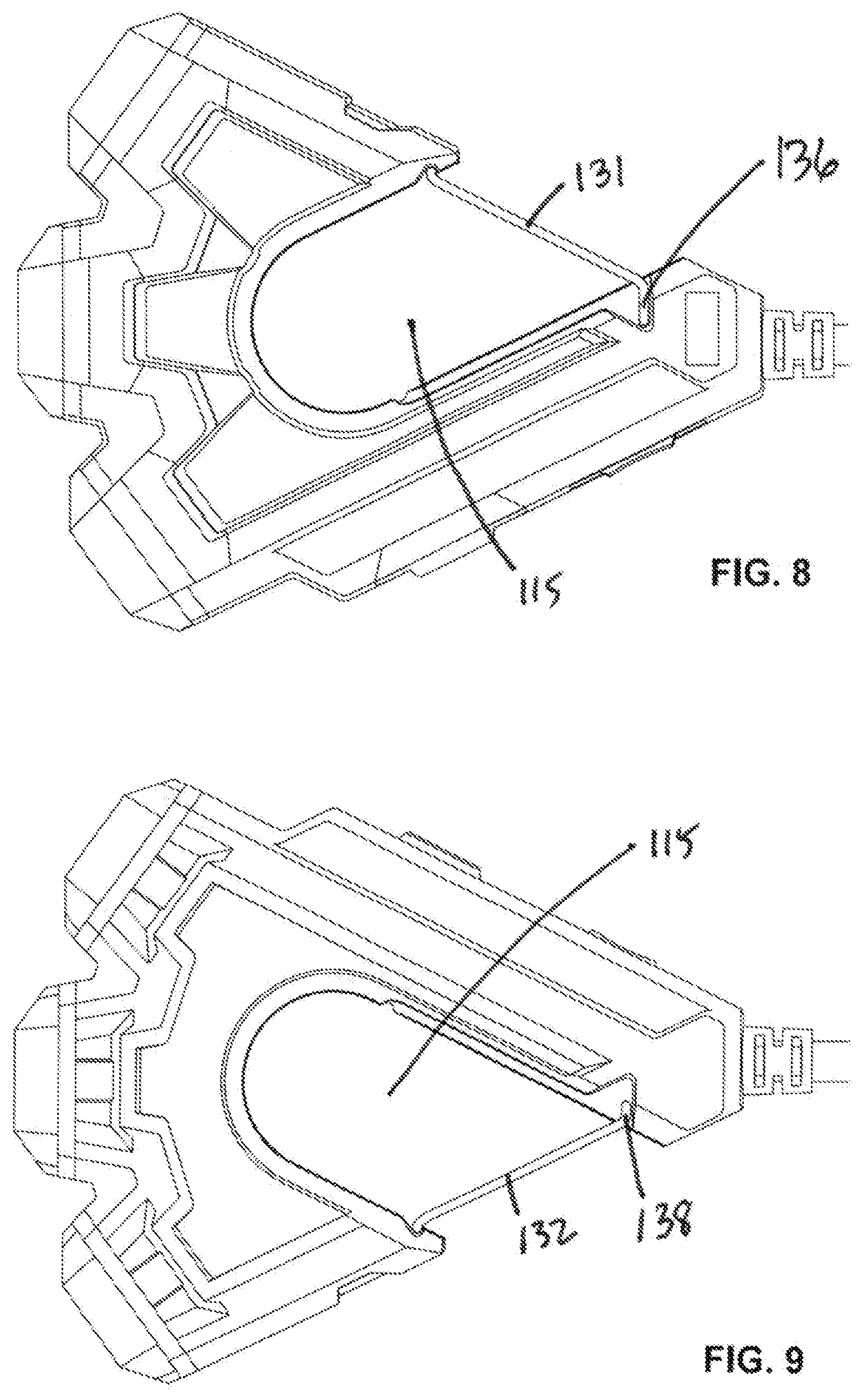
[0011] FIG. 8 is a top view of a preferred embodiment.
[0012] FIG. 9 is a bottom view of a preferred embodiment.
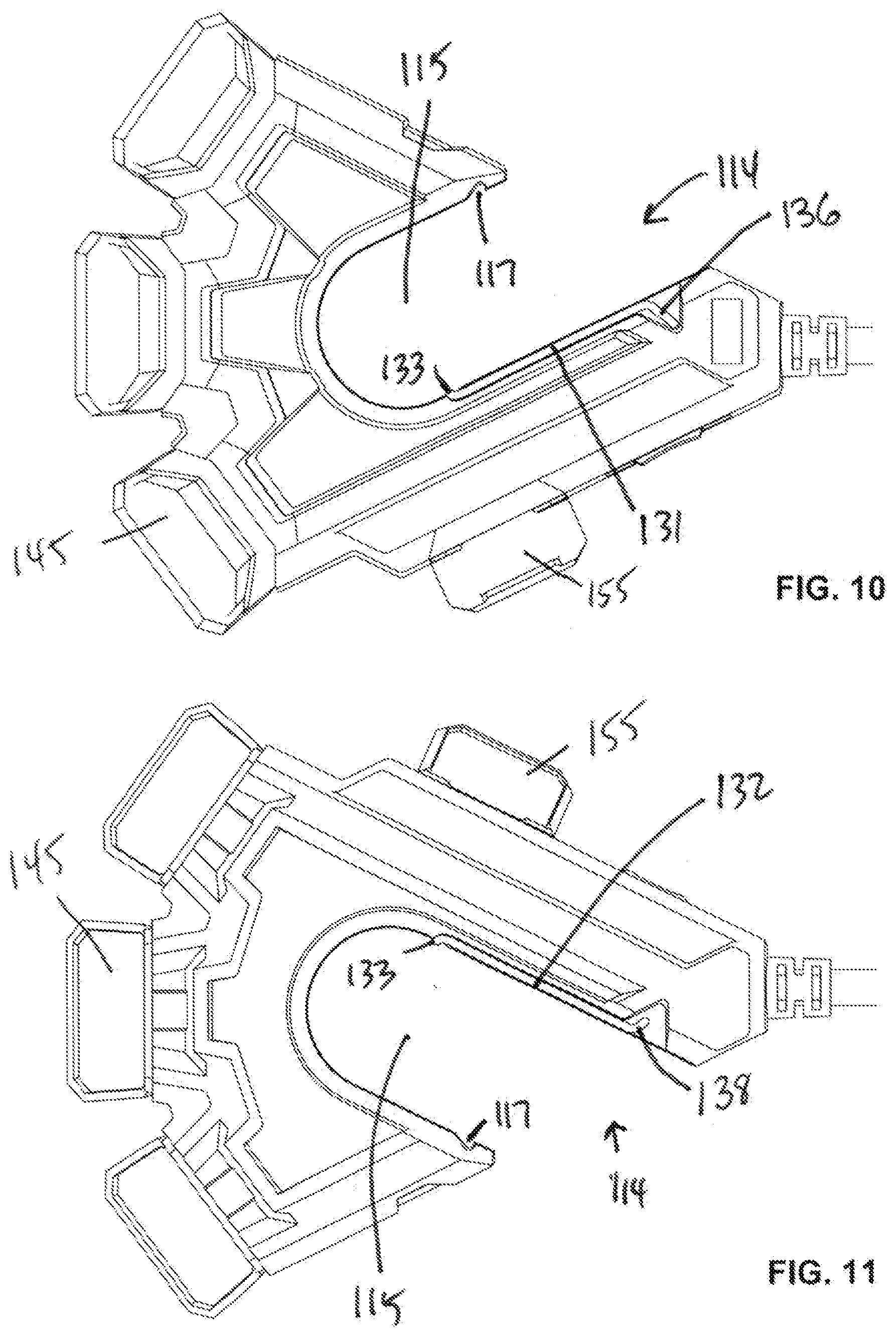
[0013] FIG. 10 is a top view of a preferred embodiment.
[0014] FIG. 11 is a bottom view of a preferred embodiment.
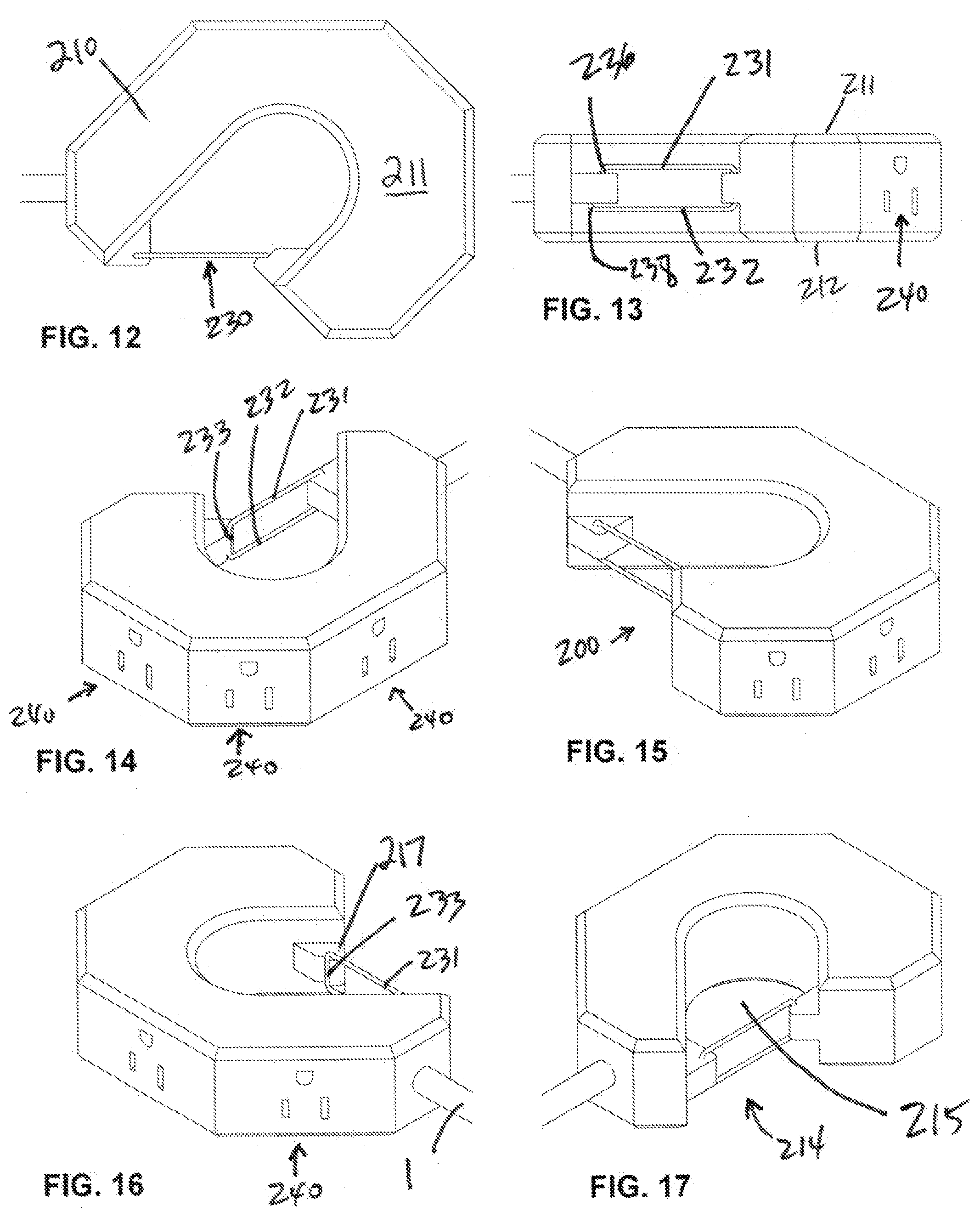
[0015] FIG. 12 is a top view of a fourth embodiment.
[0016] FIG. 13 is a side view of a fourth embodiment.
[0017] FIG. 14 is a perspective view of a fourth embodiment.
[0018] FIG. 15 is a perspective view of a fourth embodiment.
[0019] FIG. 16 is a perspective view of a fourth embodiment.
[0020] FIG. 17 is a perspective view of a fourth embodiment.
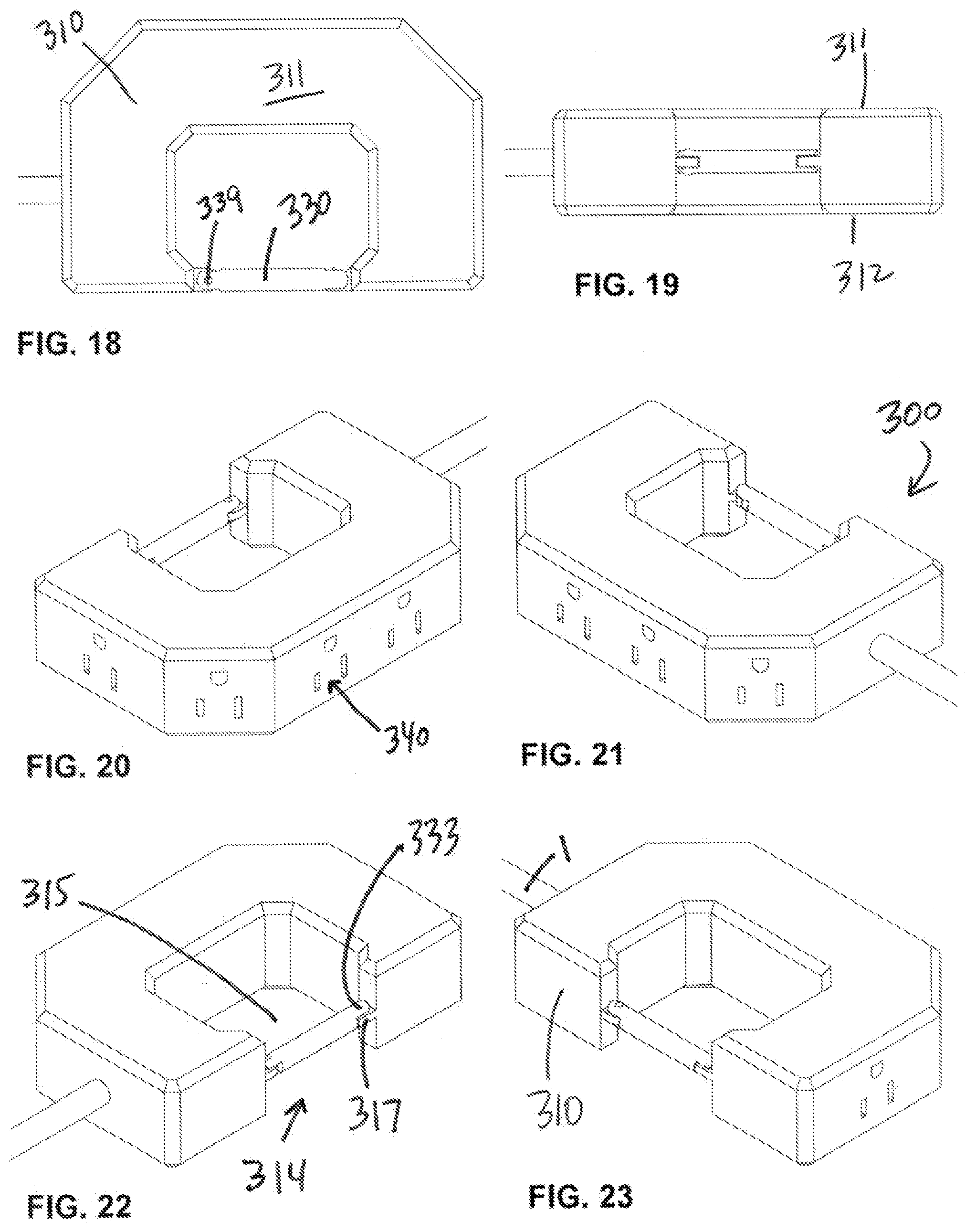
[0021] FIG. 18 is a top view of a fifth embodiment.
[0022] FIG. 19 is a side view of a fifth embodiment.
[0023] FIG. 20 is a perspective view of a fifth embodiment.
[0024] FIG. 21 is a perspective view of a fifth embodiment.
[0025] FIG. 22 is a perspective view of a fifth embodiment.
[0026] FIG. 23 is a perspective view of a fifth embodiment.
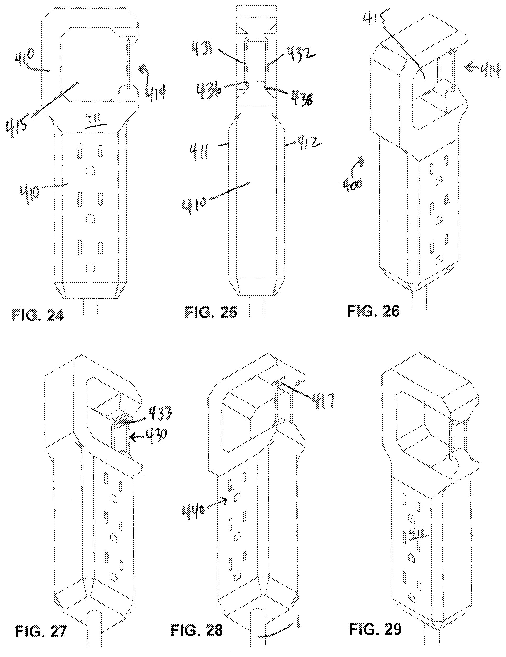
[0027] FIG. 24 is a top view of a sixth embodiment.
[0028] FIG. 25 is a side view of a sixth embodiment.
[0029] FIG. 26 is a perspective view of a sixth embodiment.
[0030] FIG. 27 is a perspective view of a sixth embodiment.
[0031] FIG. 28 is a perspective view of a sixth embodiment.
[0032] FIG. 29 is a perspective view of a sixth embodiment.
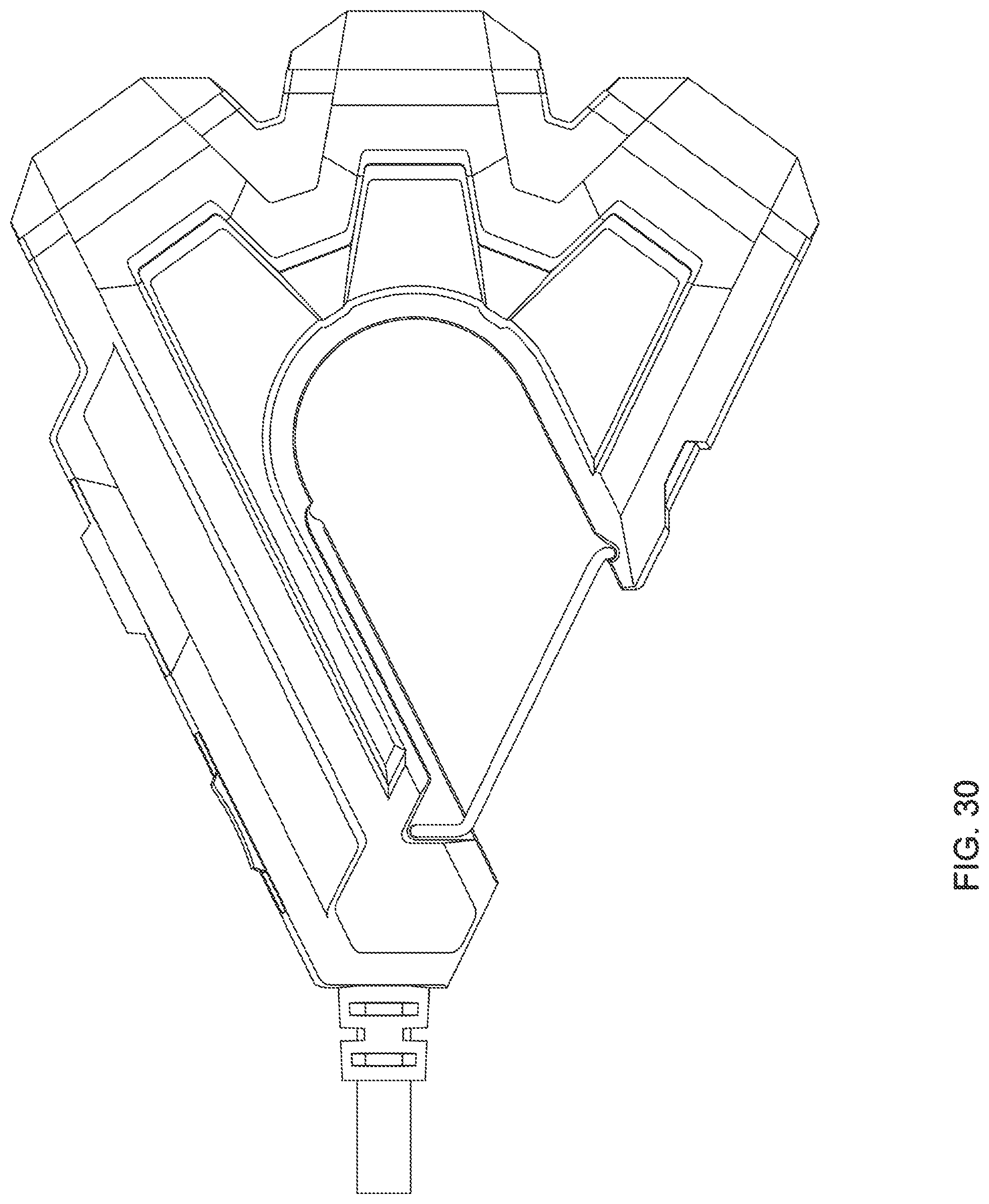
[0033] FIG. 30 is a top view of a preferred embodiment depicted with a gate and doors closed.
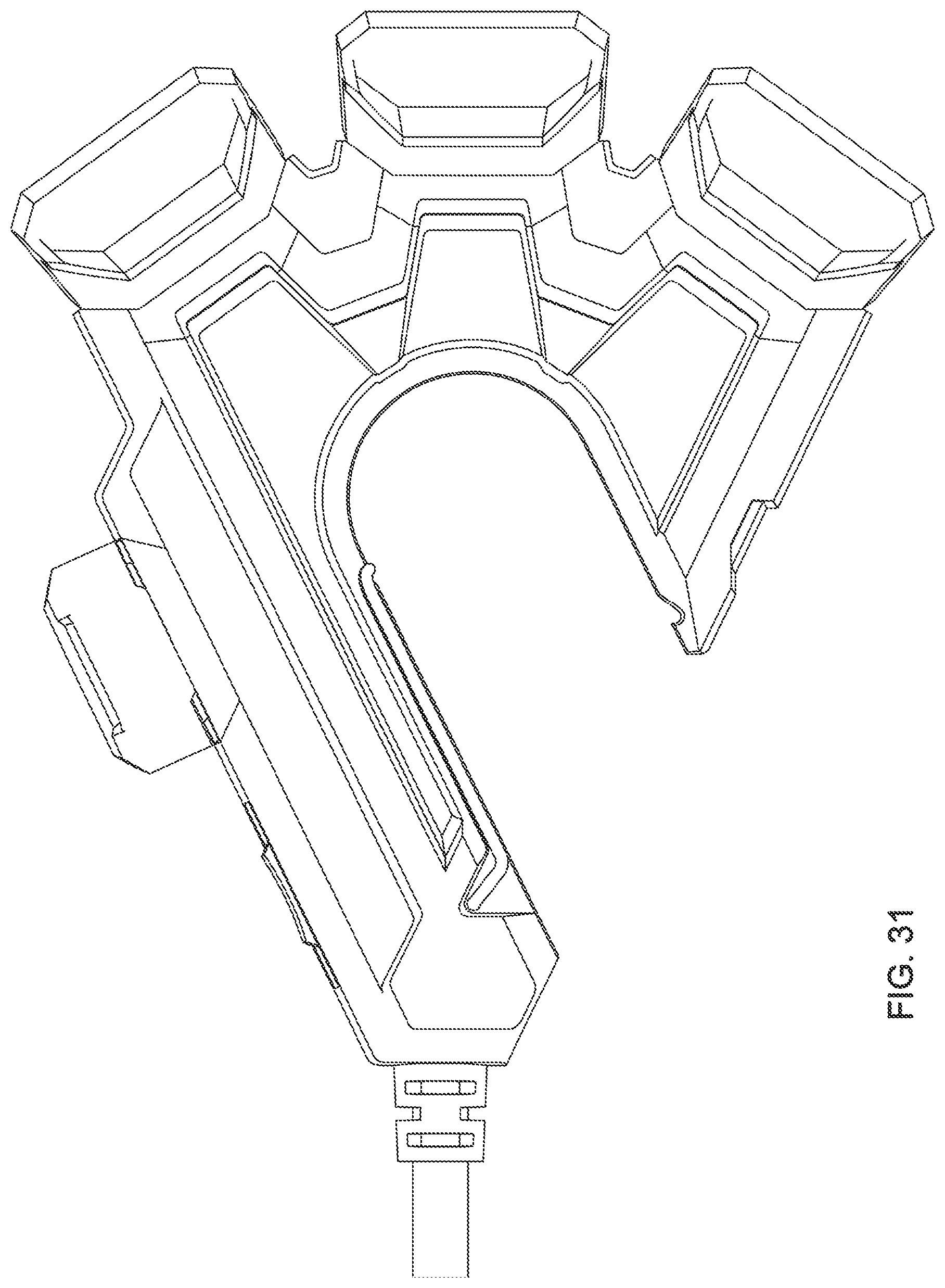
[0034] FIG. 31 is a top view of a preferred embodiment depicted with a gate and doors open.
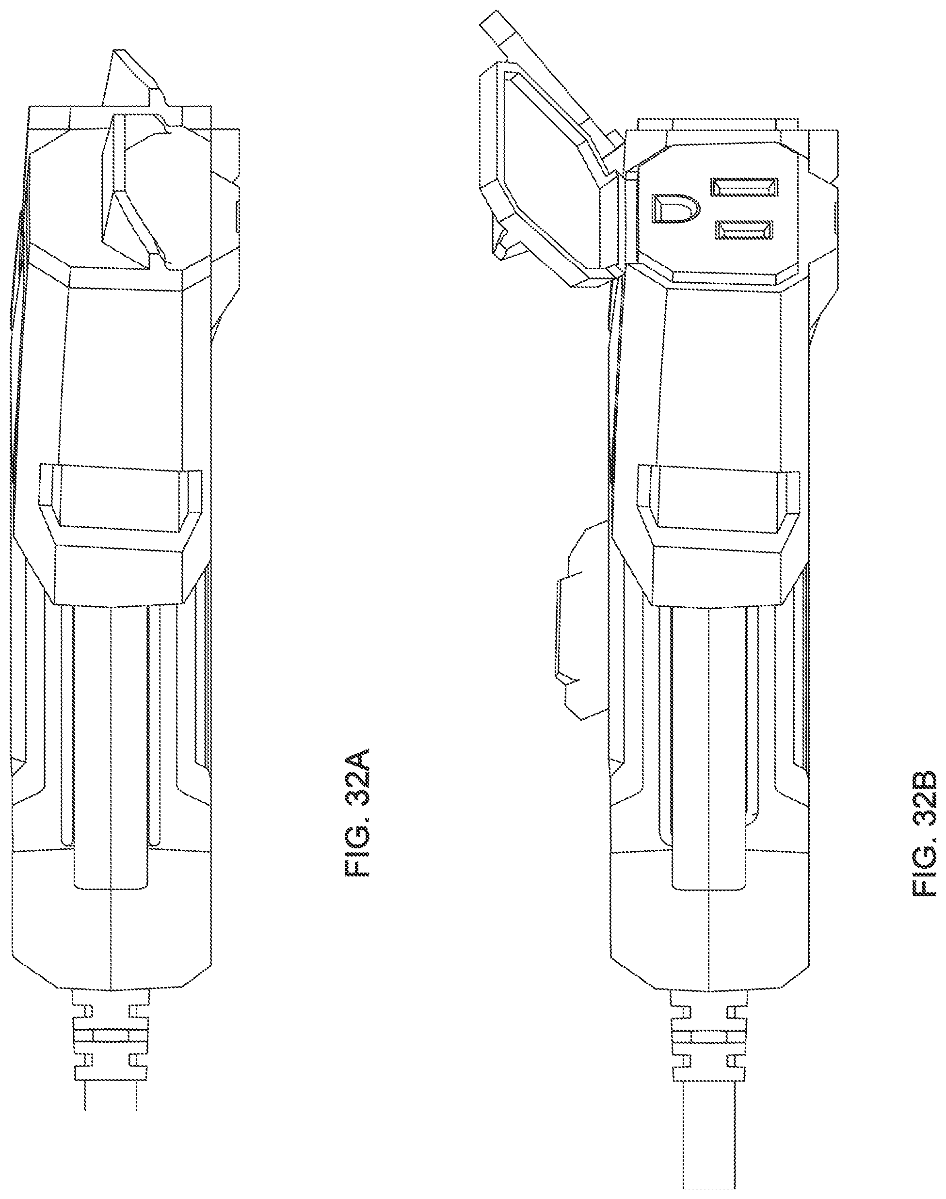
[0035] FIG. 32A is a side view of a preferred embodiment depicted with a gate and doors closed.
[0036] FIG. 32B is a side view of a preferred embodiment depicted with a gate and doors open.
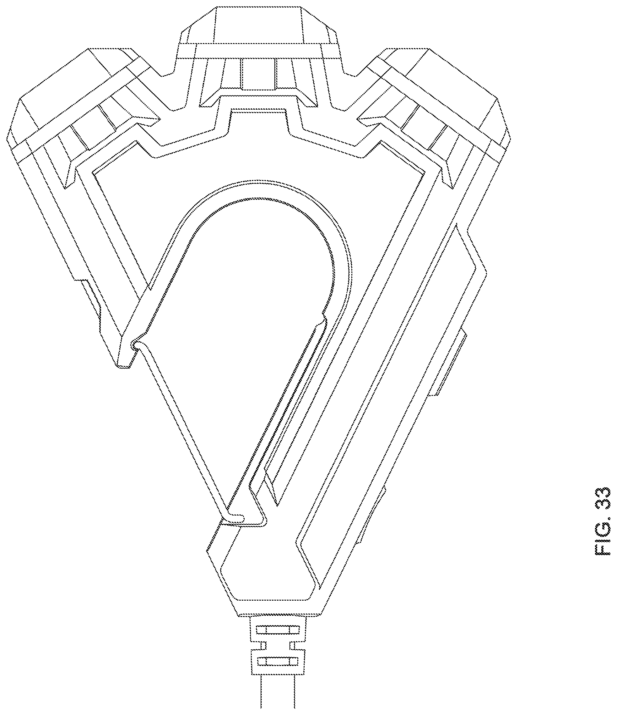
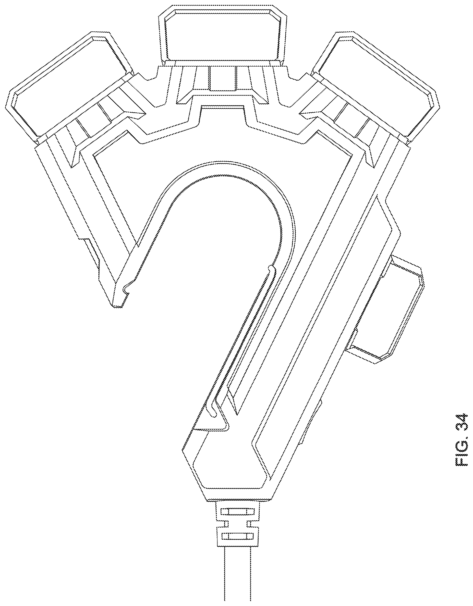
[0037] FIG. 33 is a bottom view of a preferred embodiment depicted with a gate and doors closed.
[0038] FIG. 34 is a bottom view of a preferred embodiment depicted with a gate and doors open.
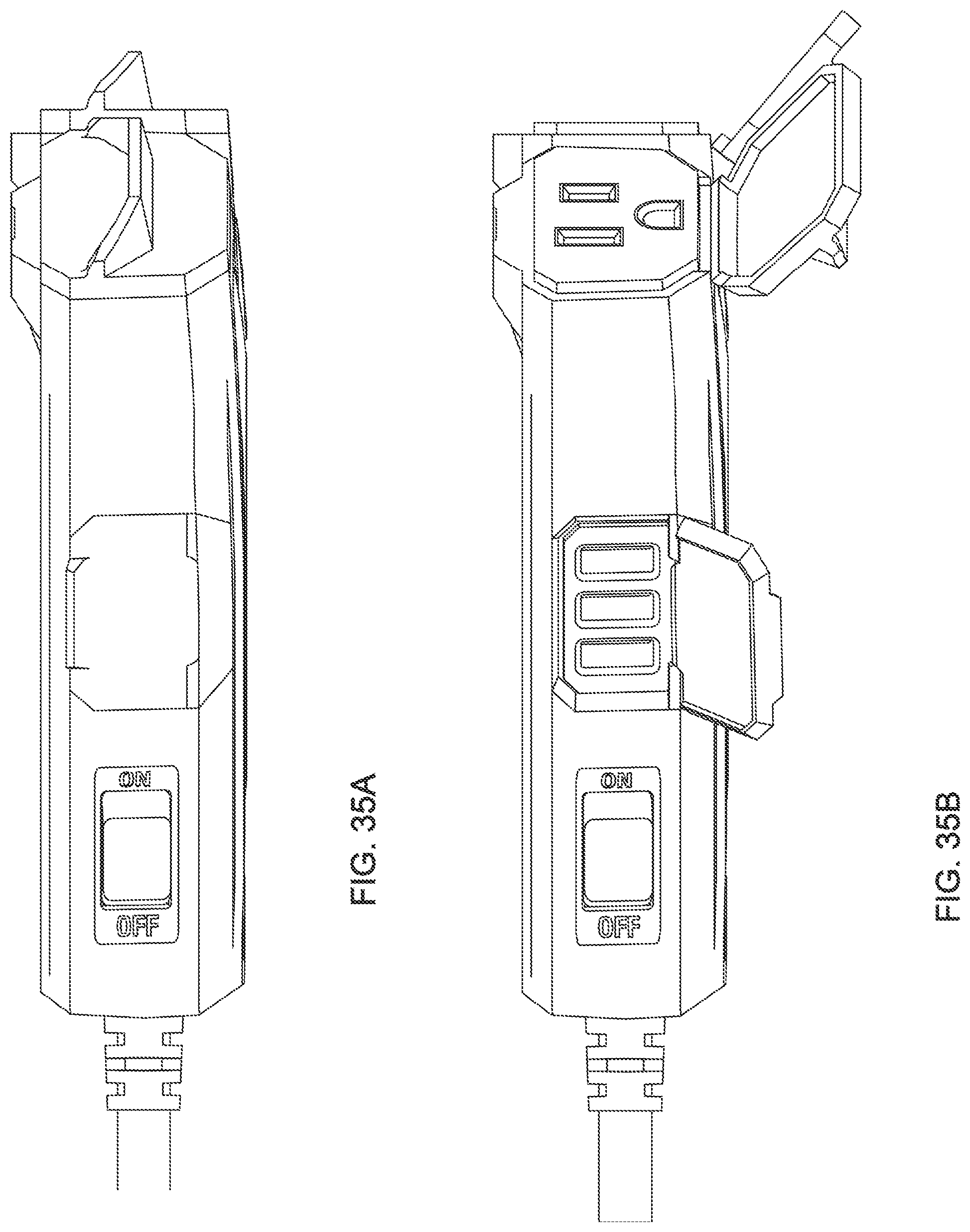
[0039] FIG. 35A is a side view of a preferred embodiment depicted with a gate and doors closed.
[0040] FIG. 35B is a side view of a preferred embodiment depicted with a gate and doors open.
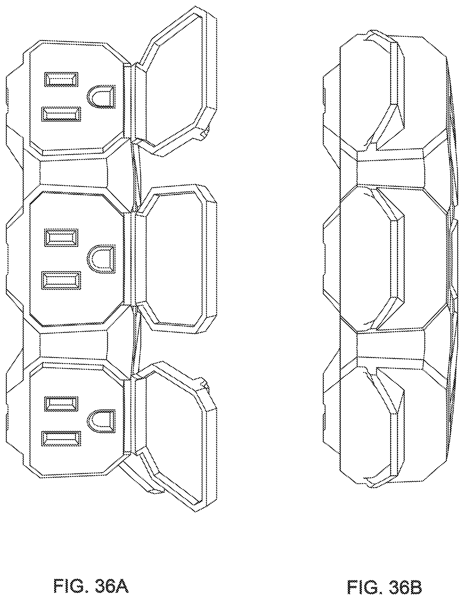
[0041] FIG. 36A is a front view of a preferred embodiment depicted with a gate and doors open.
[0042] FIG. 36B is a front view of a preferred embodiment depicted with a gate and doors closed.
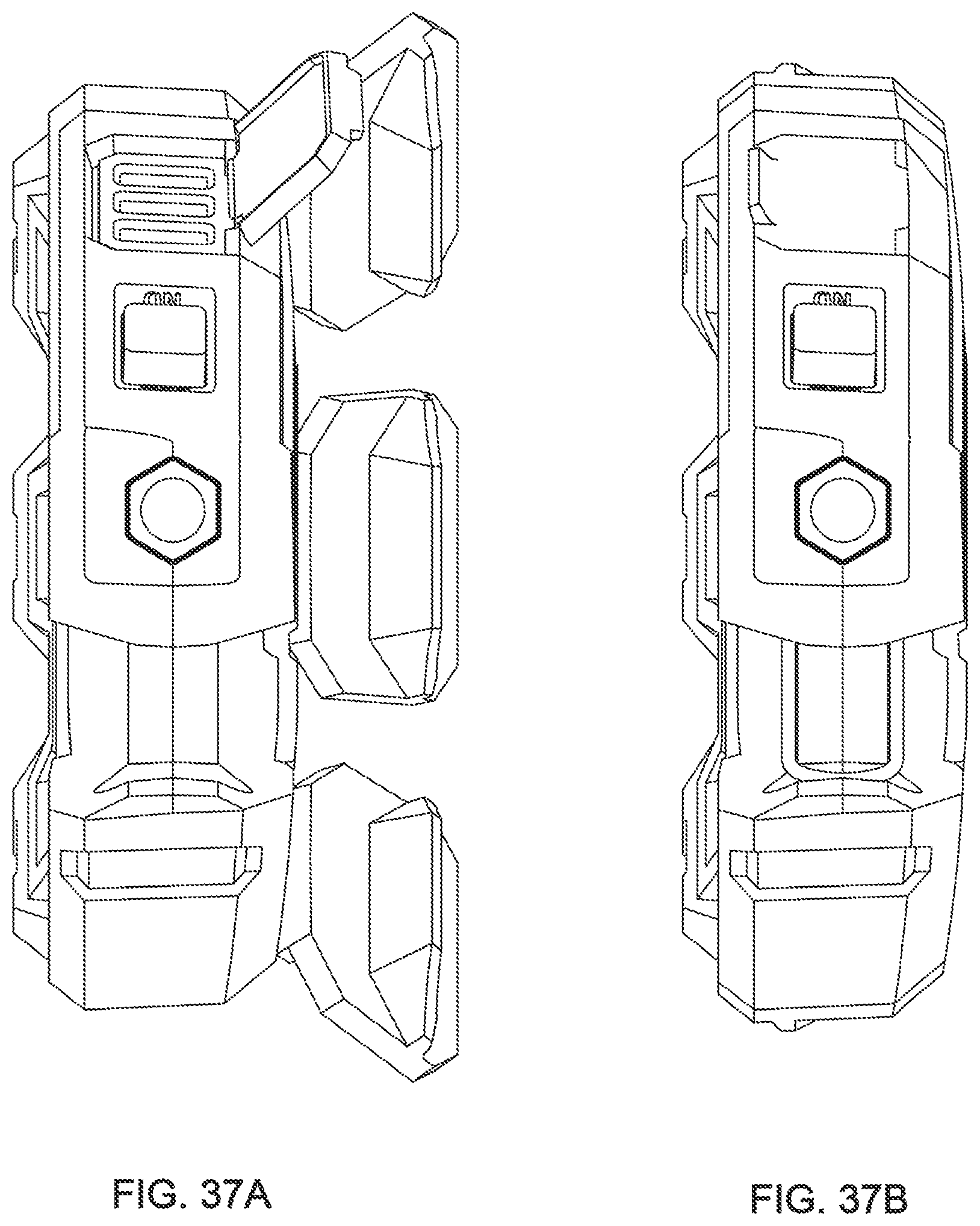
[0043] FIG. 37A is a back view of a preferred embodiment depicted with a gate and doors open.
[0044] FIG. 37B is a back view of a preferred embodiment depicted with a gate and doors closed.
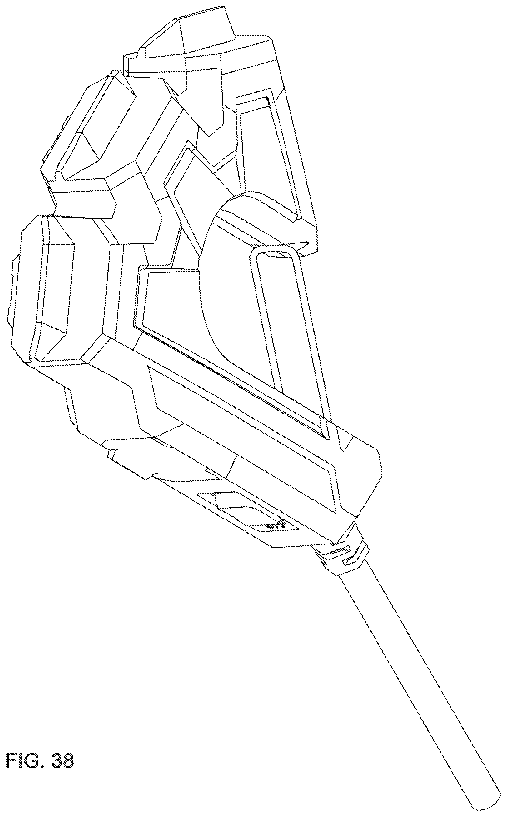
[0045] FIG. 38 is a perspective view of a preferred embodiment depicted with a gate and doors closed.
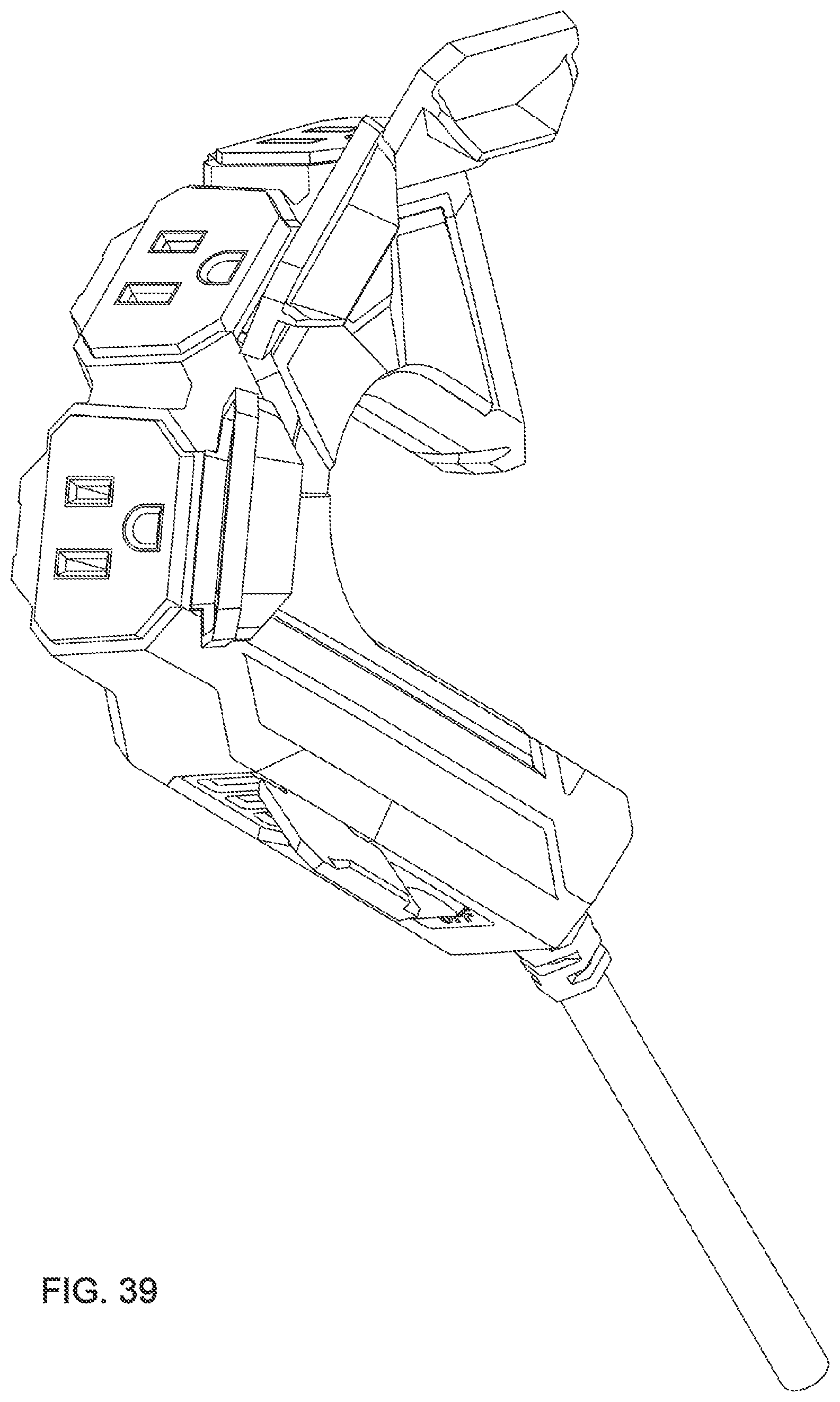
[0046] FIG. 39 is a perspective view of a preferred embodiment depicted with a gate and doors open.
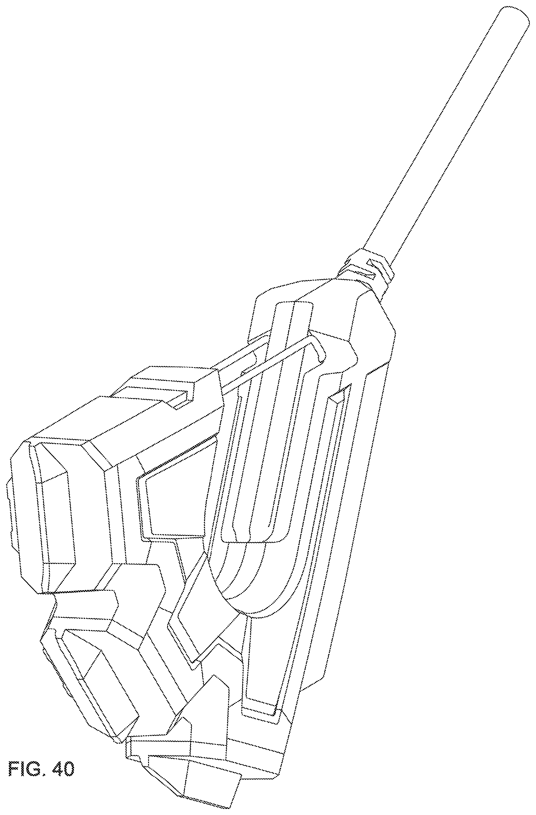
[0047] FIG. 40 is a perspective view of a preferred embodiment depicted with a gate and doors closed.
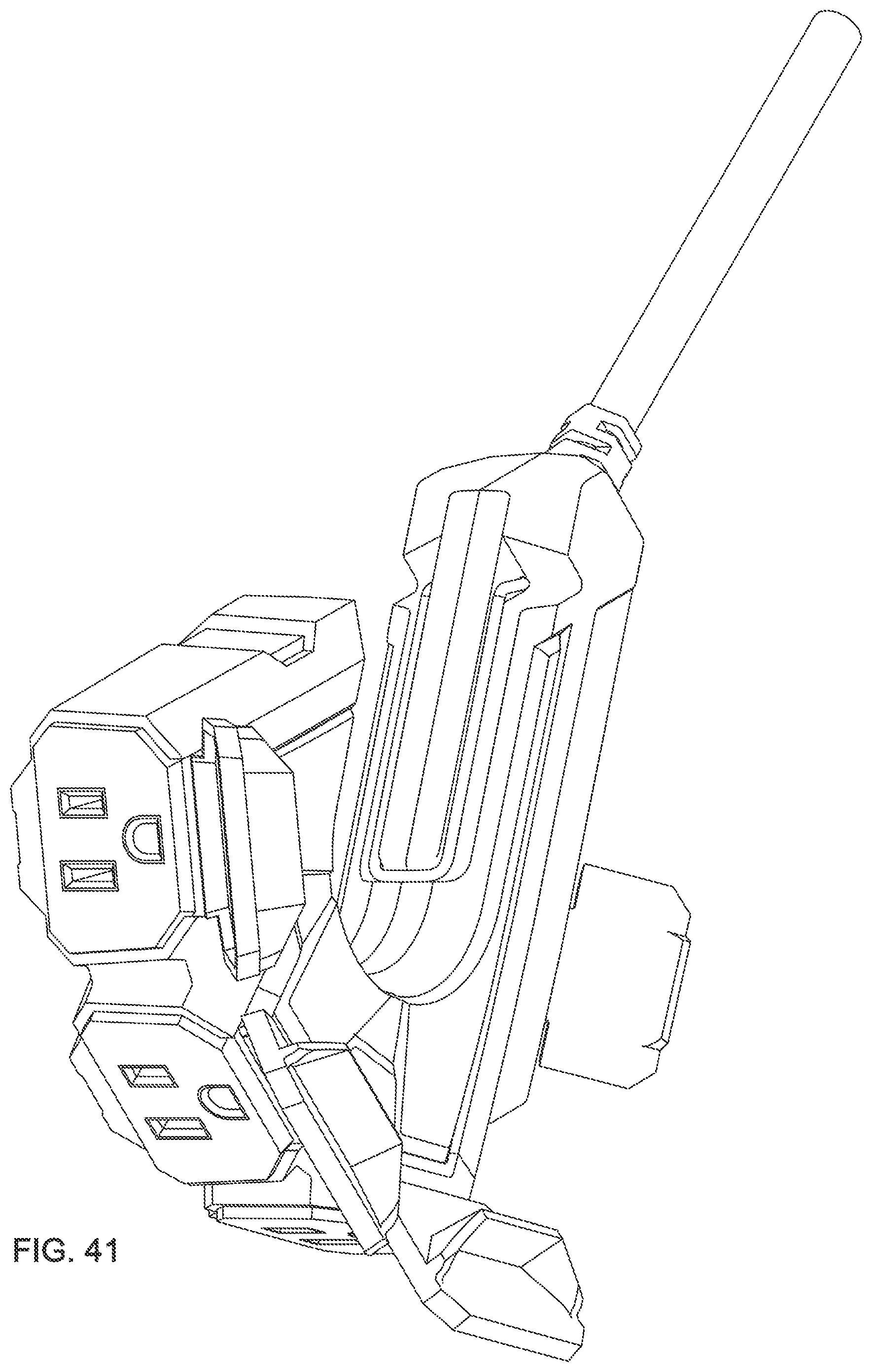
[0048] FIG. 41 is a perspective view of a preferred embodiment depicted with a gate and doors open.
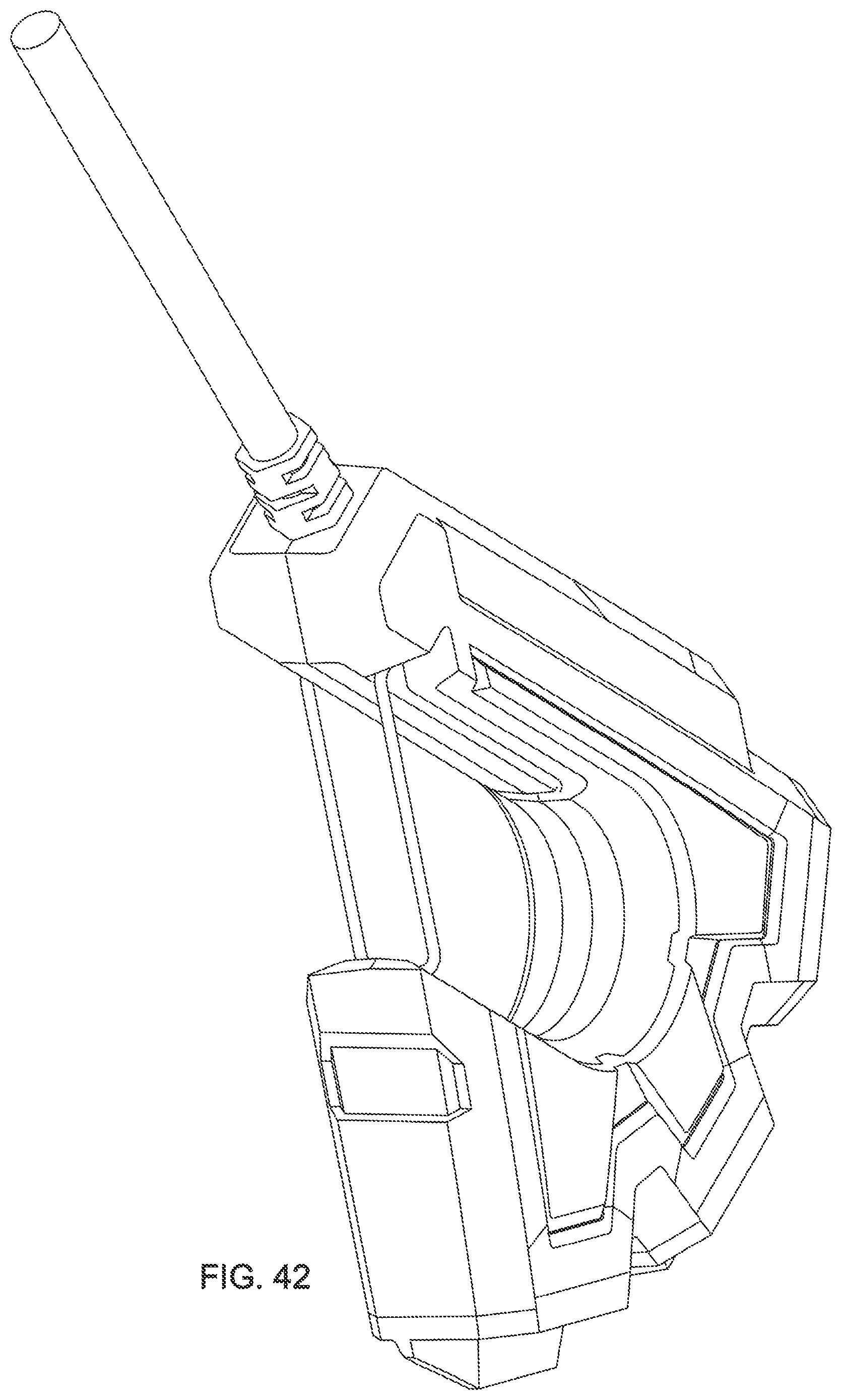
[0049] FIG. 42 is a perspective view of a preferred embodiment depicted with a gate and doors closed.
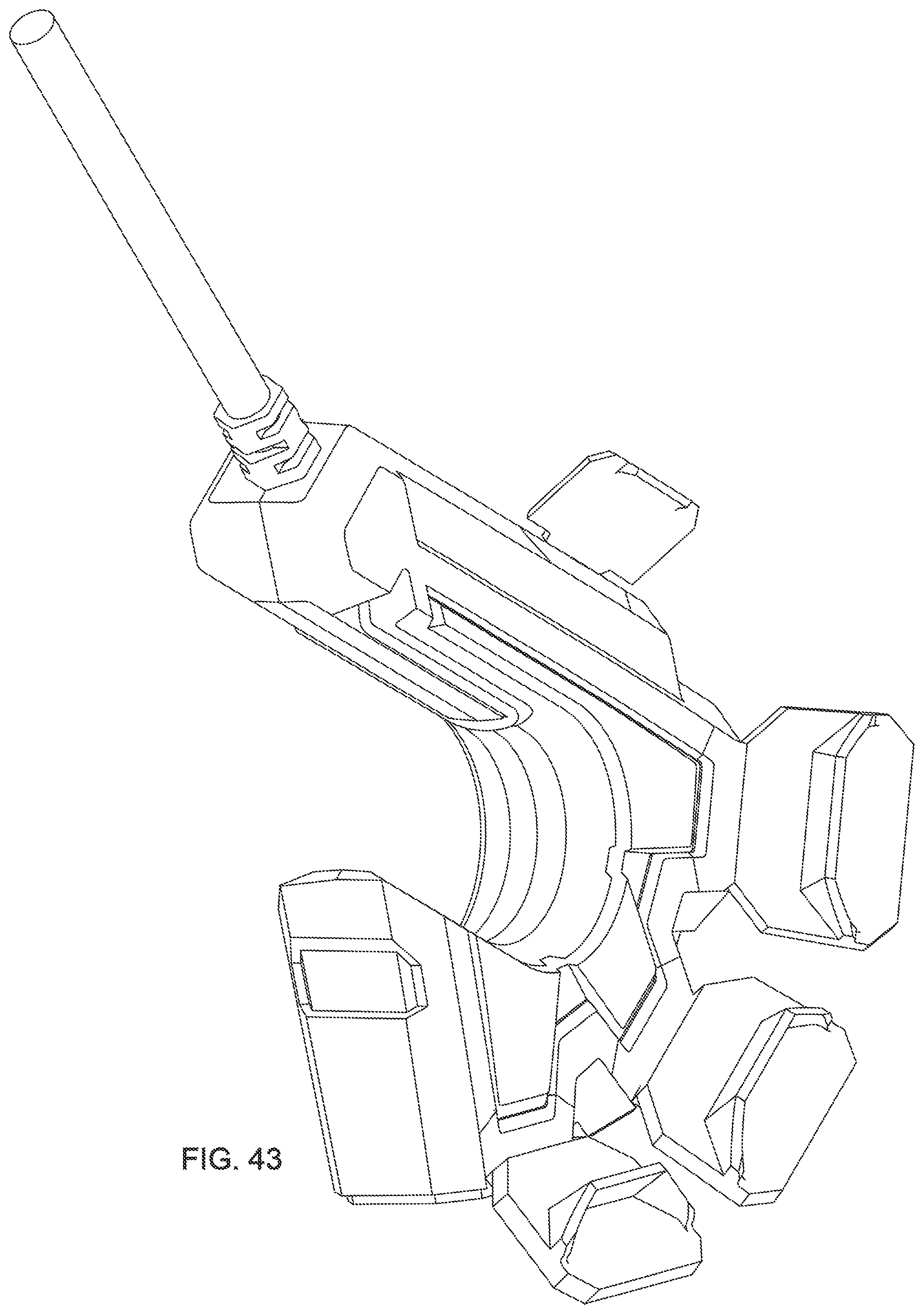
[0050] FIG. 43 is a perspective view of a preferred embodiment depicted with a gate and doors open.
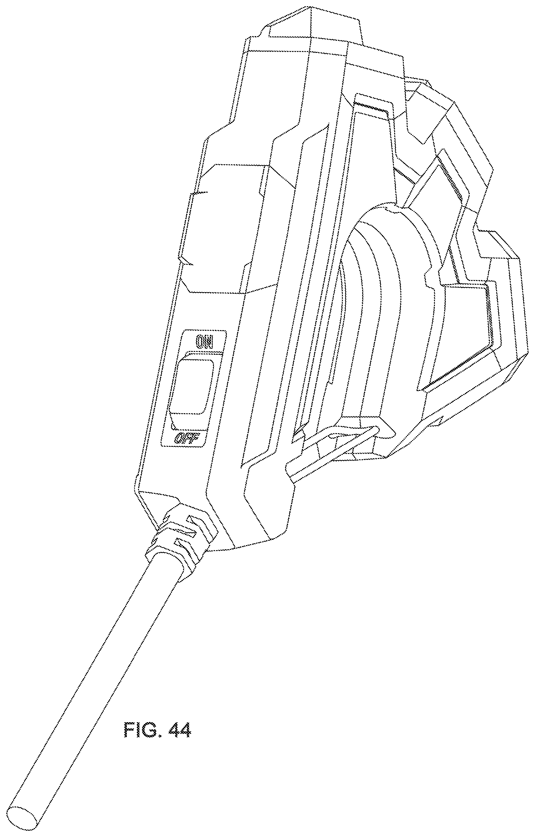
[0051] FIG. 44 is a perspective view of a preferred embodiment depicted with a gate and doors closed.
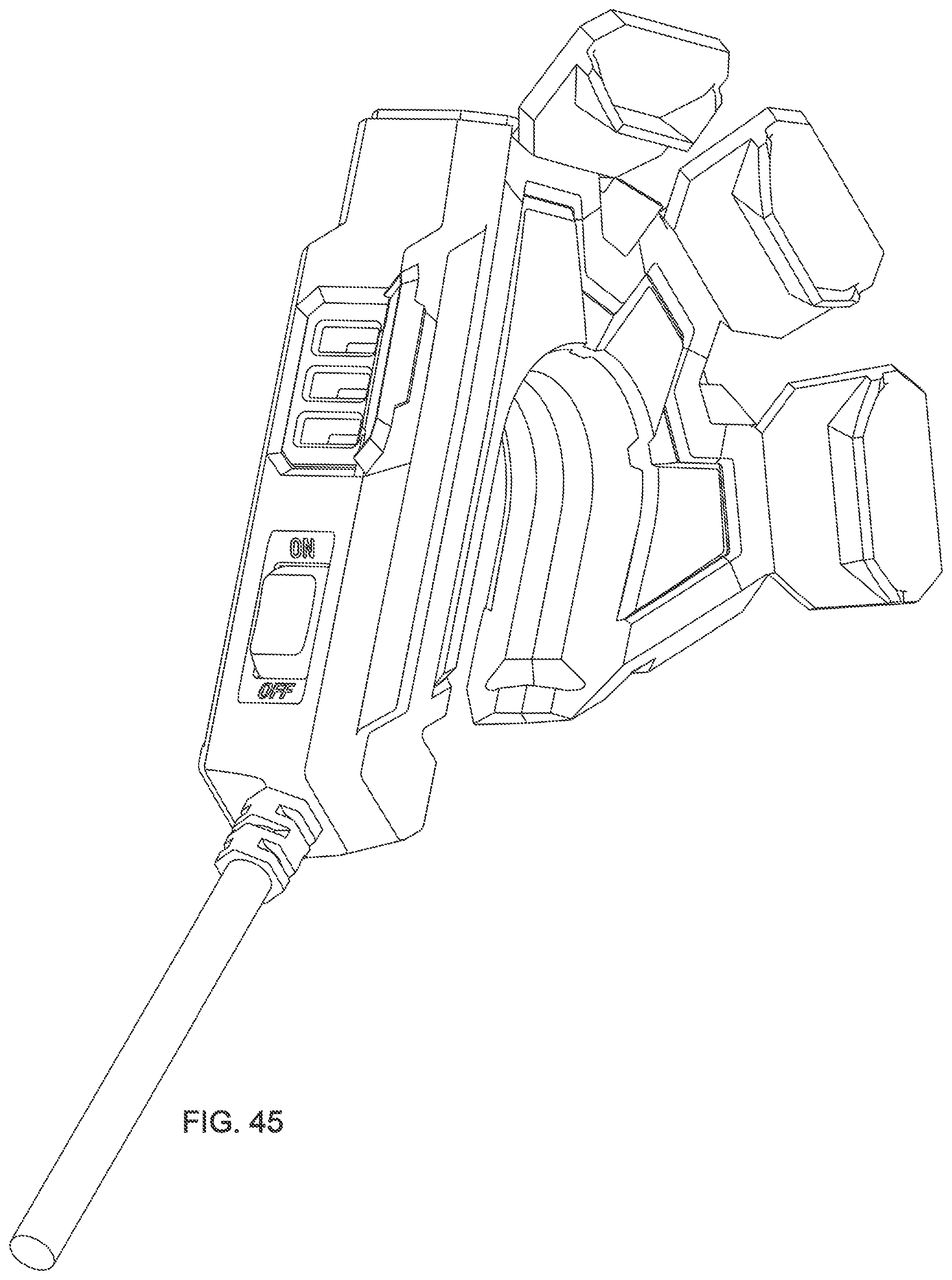
[0052] FIG. 45 is a perspective view of a preferred embodiment depicted with a gate and doors open.
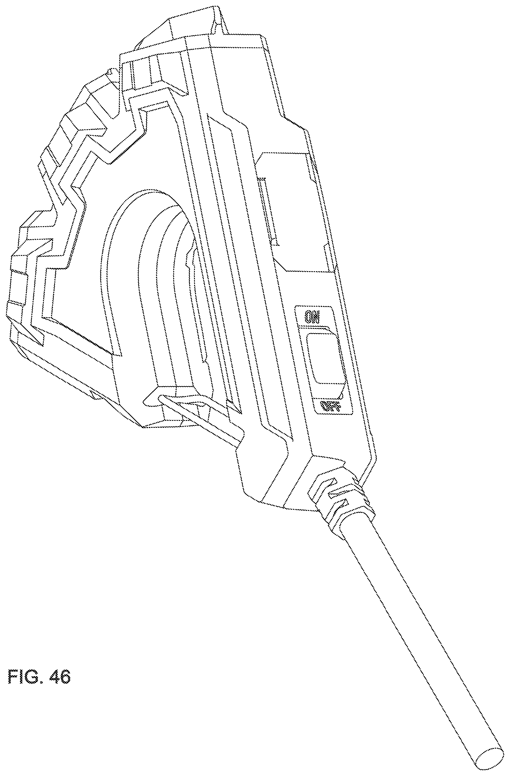
[0053] FIG. 46 is a perspective view of a preferred embodiment depicted with a gate and doors closed.
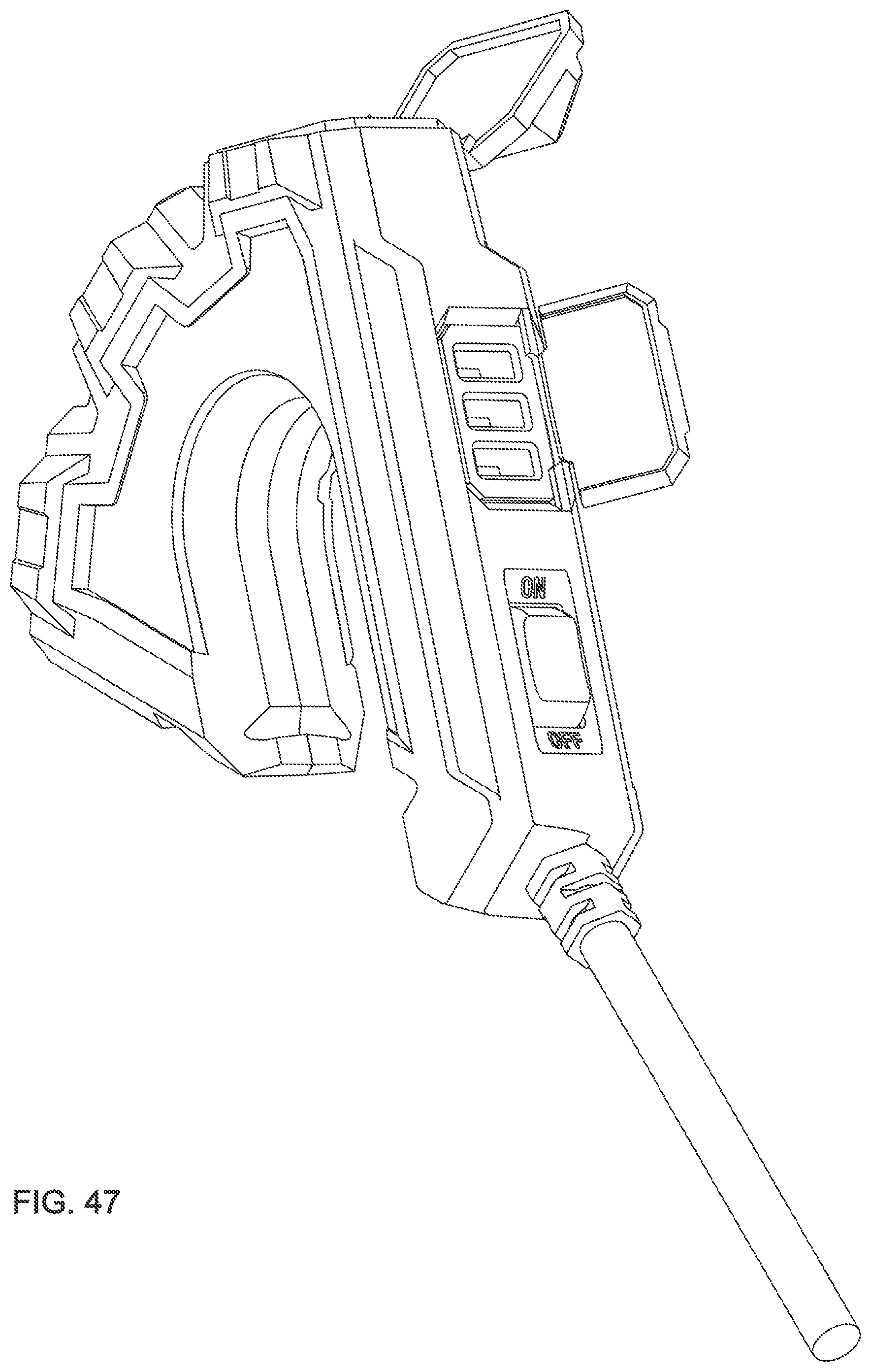
[0054] FIG. 47 is a perspective view of a preferred embodiment depicted with a gate and doors open.
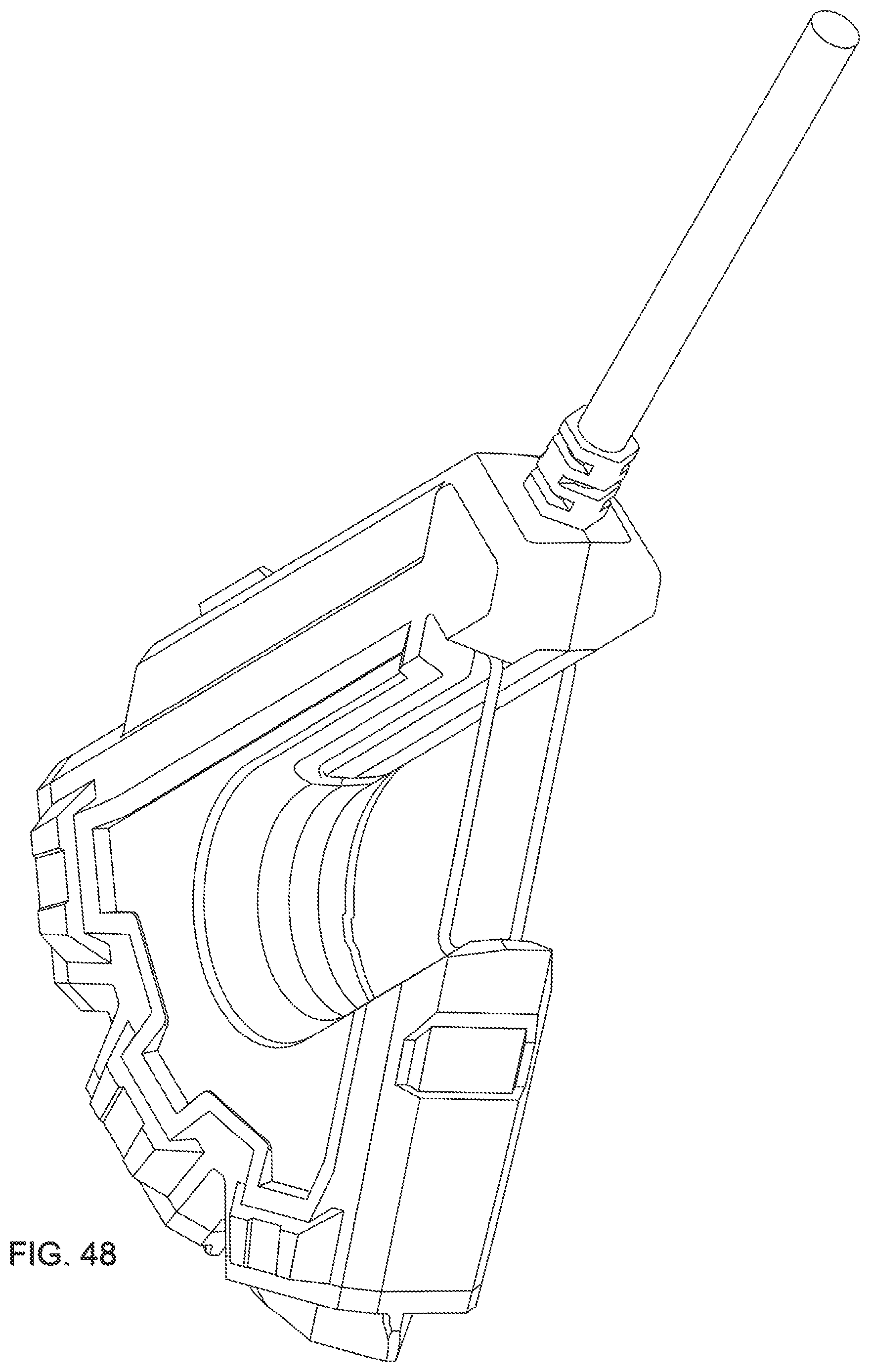
[0055] FIG. 48 is a perspective view of a preferred embodiment depicted with a gate and doors closed.
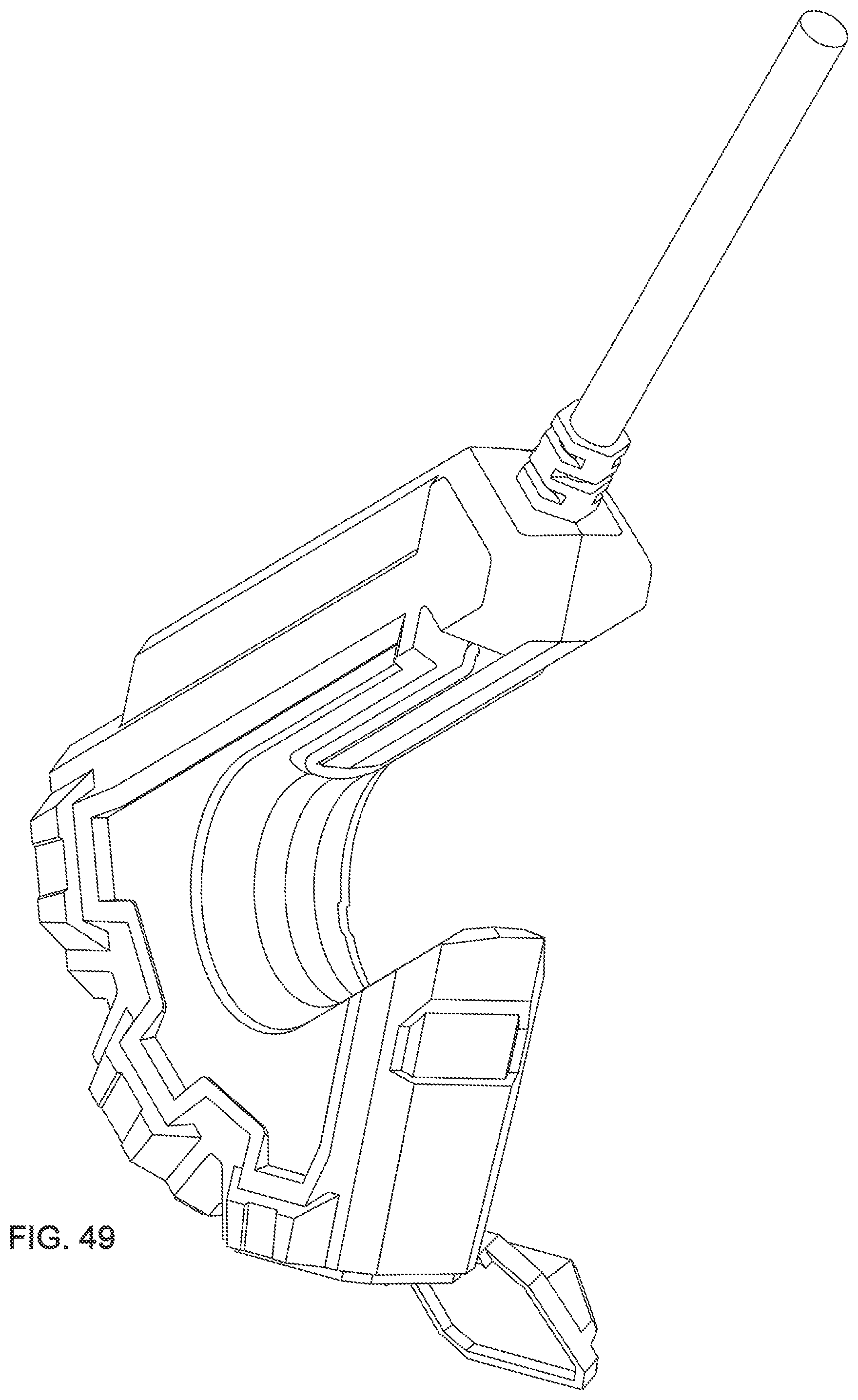
[0056] FIG. 49 is a perspective view of a preferred embodiment depicted with a gate and doors open.
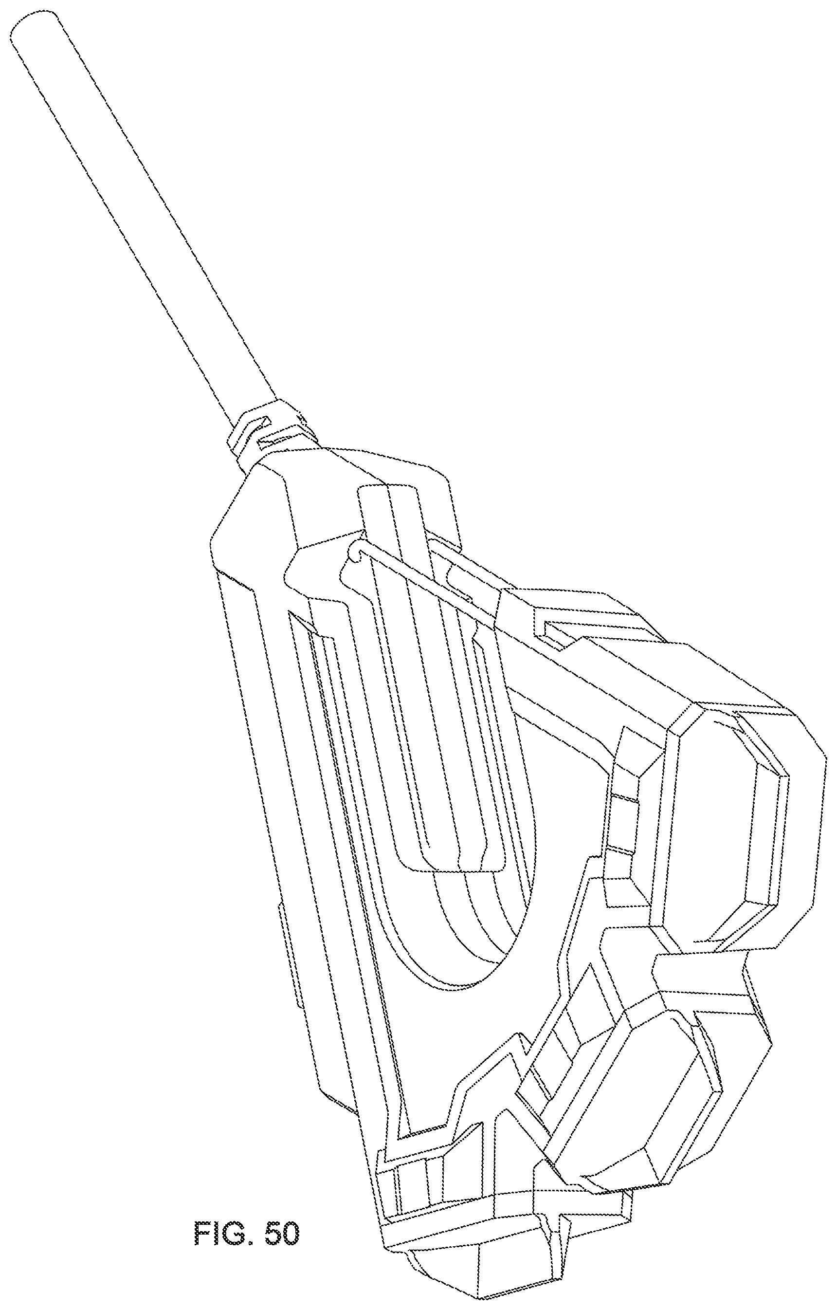
[0057] FIG. 50 is a perspective view of a preferred embodiment depicted with a gate and doors closed.
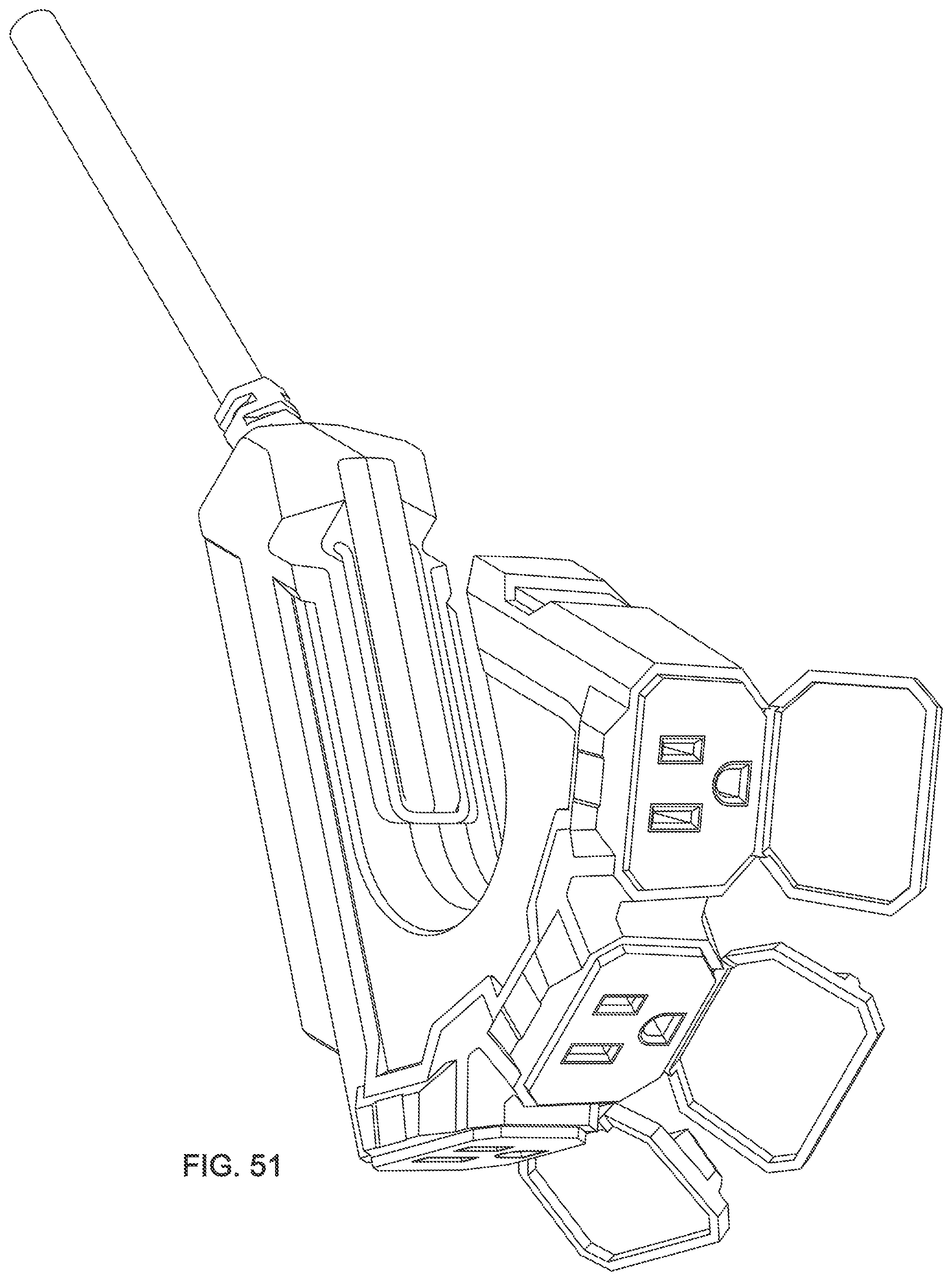
[0058] FIG. 51 is a perspective view of a preferred embodiment depicted with a gate and doors open.
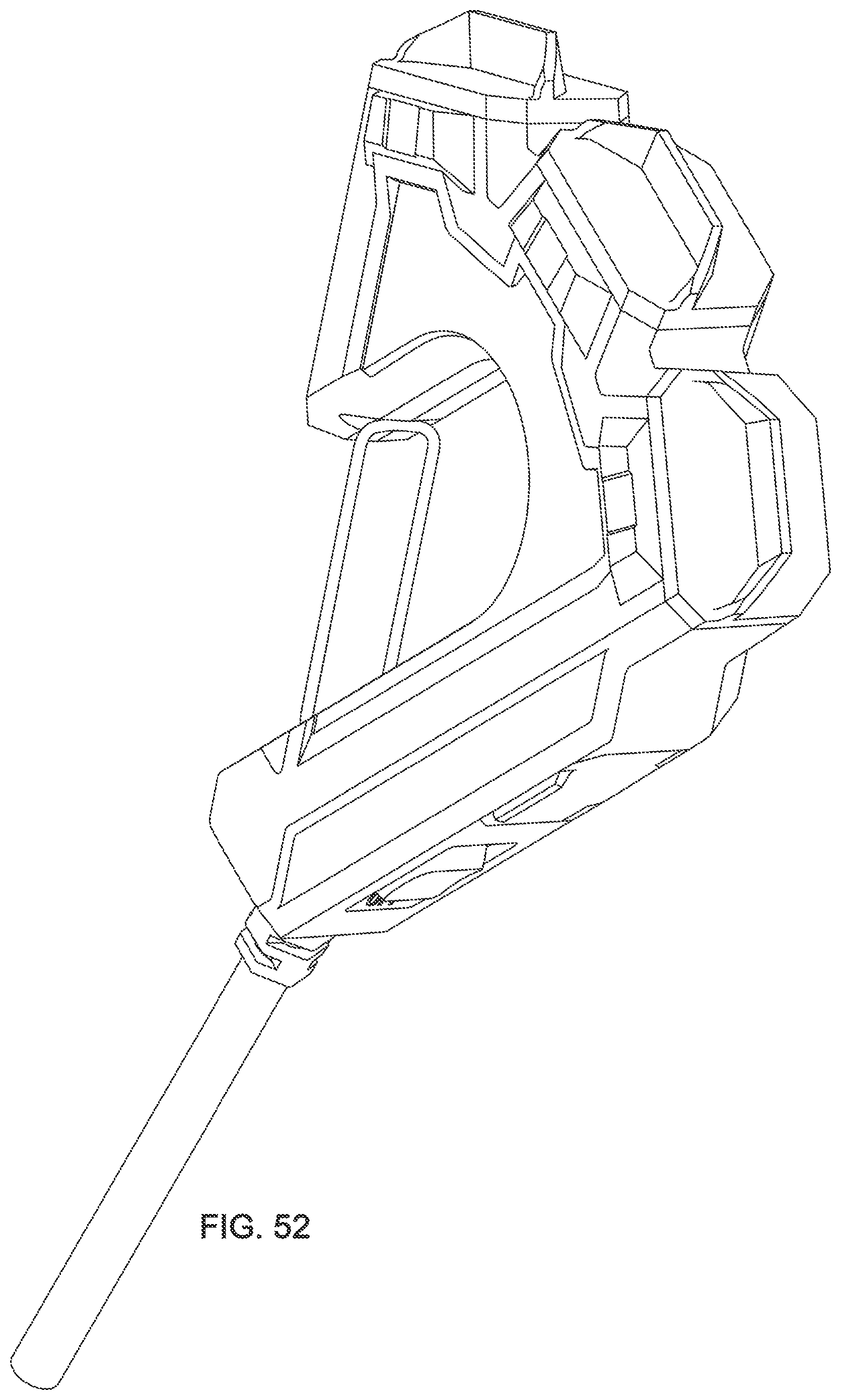
[0059] FIG. 52 is a perspective view of a preferred embodiment depicted with a gate and doors closed.
[0060] FIG. 53 is a perspective view of a preferred embodiment depicted with a gate and doors open.
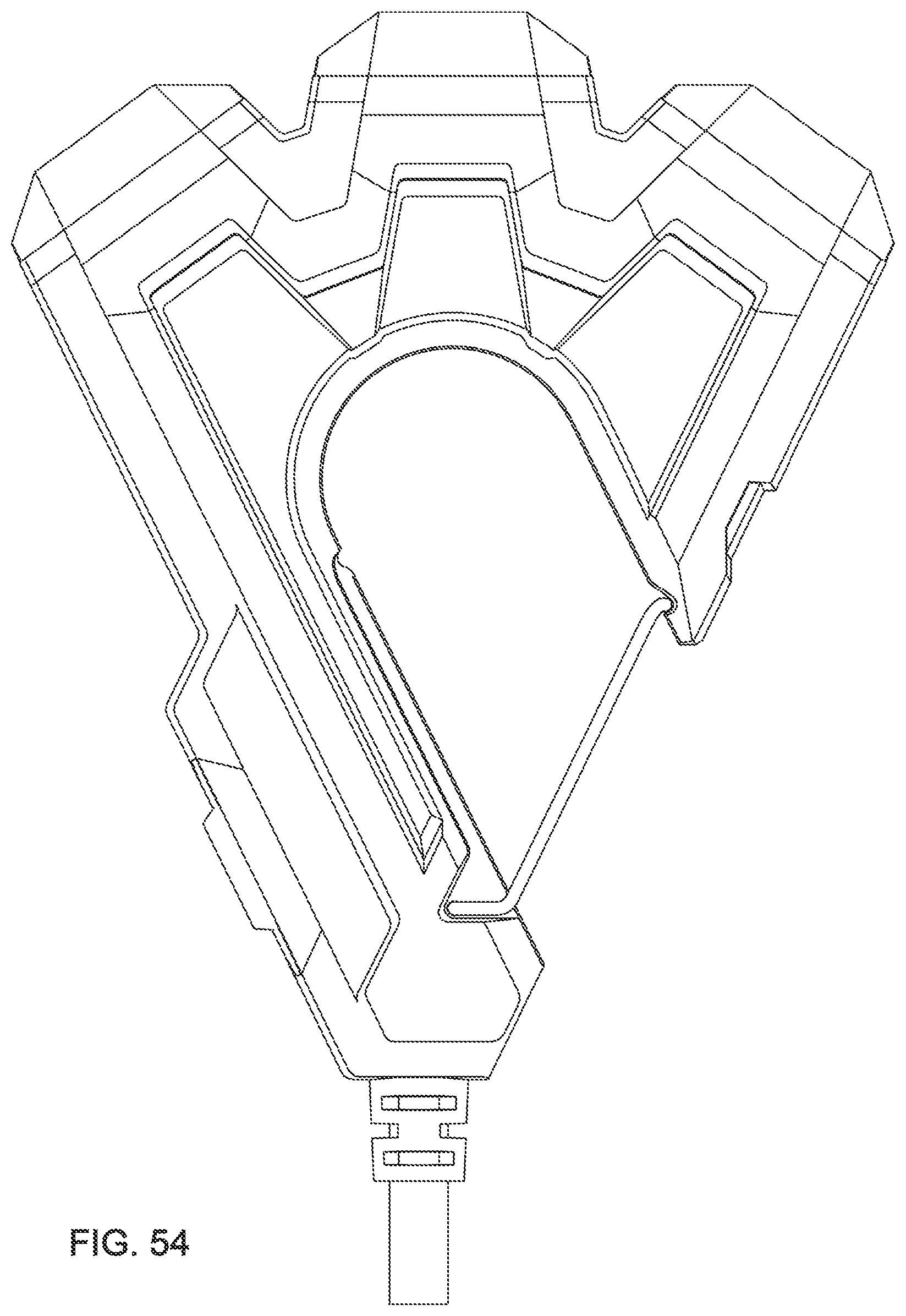
[0061] FIG. 54 is a top view of a second embodiment depicted with a gate and doors closed.
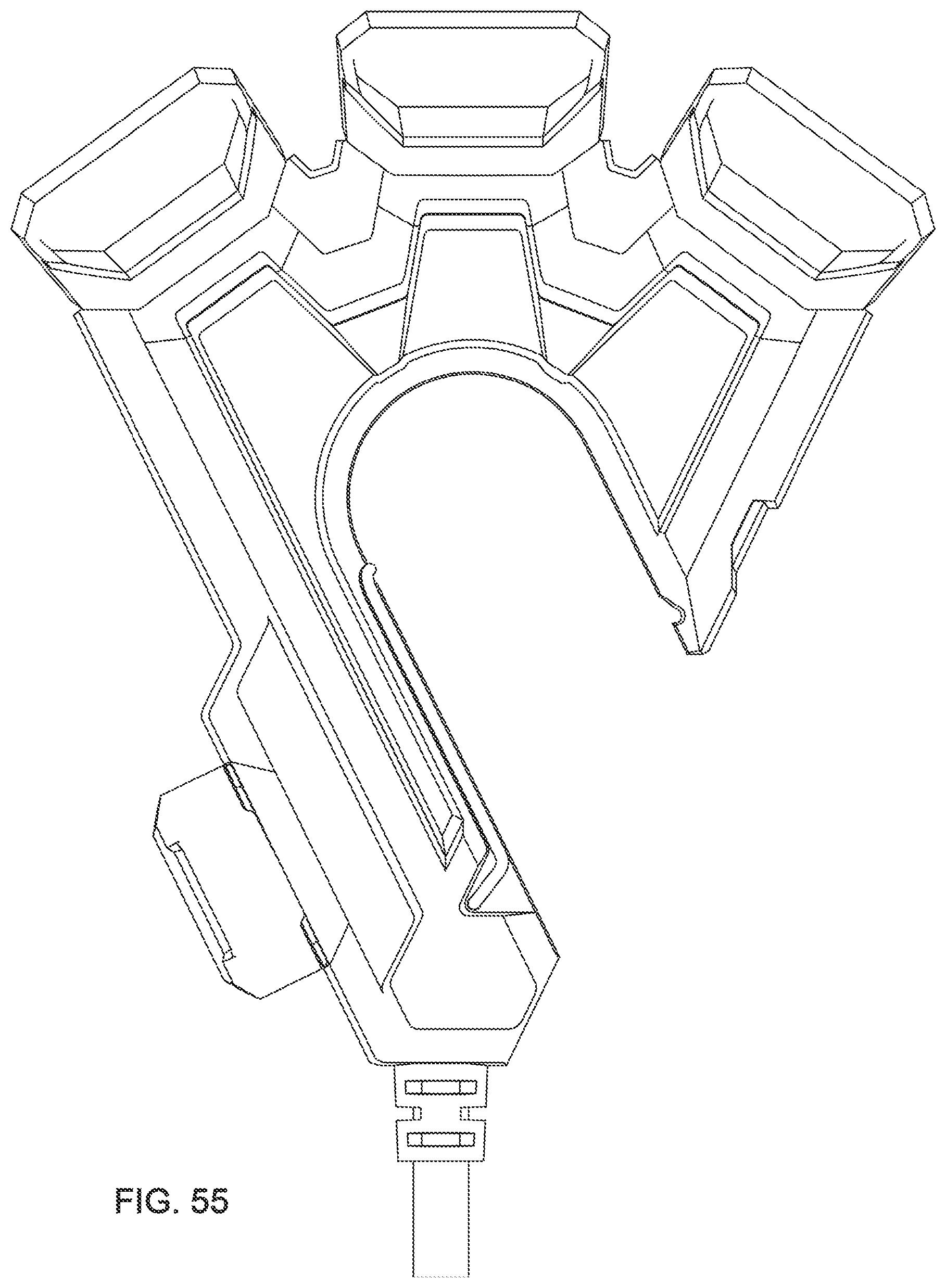
[0062] FIG. 55 is a top view of a second embodiment depicted with a gate and doors open.
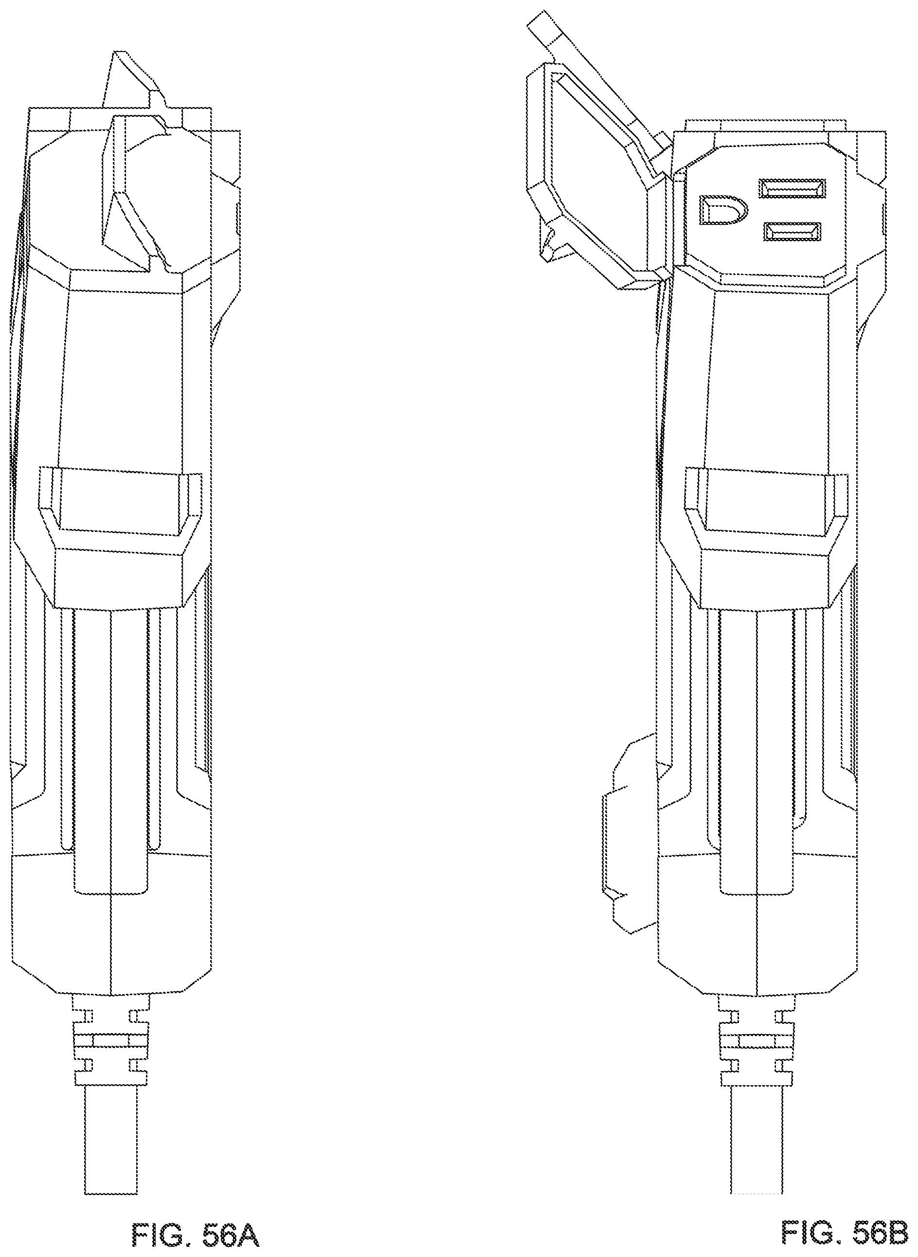
[0063] FIG. 56A is a side view of a second embodiment depicted with a gate and doors closed.
[0064] FIG. 56B is a side view of a second embodiment depicted with a gate and doors open.
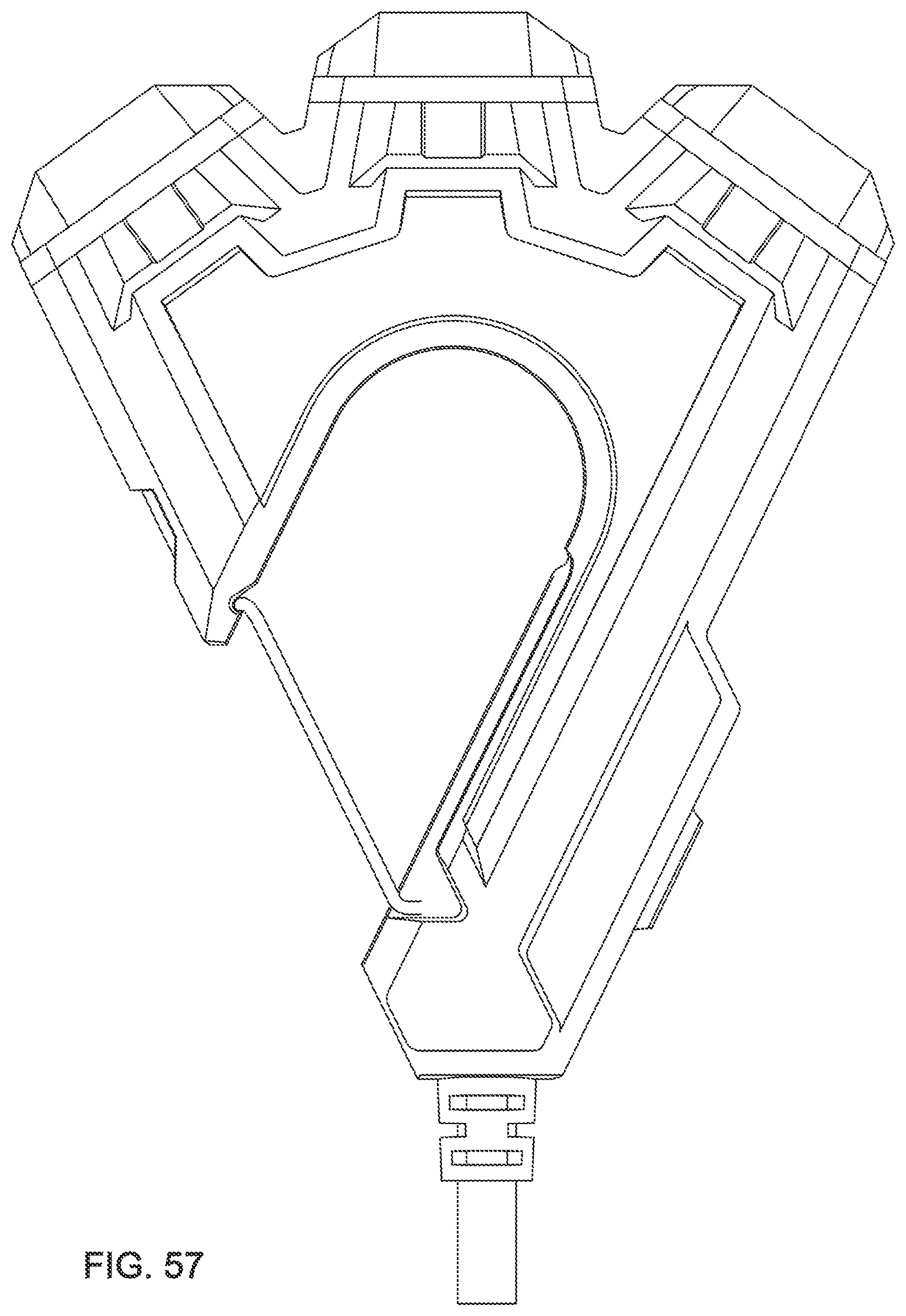
[0065] FIG. 57 is a bottom view of a second embodiment depicted with a gate and doors closed.
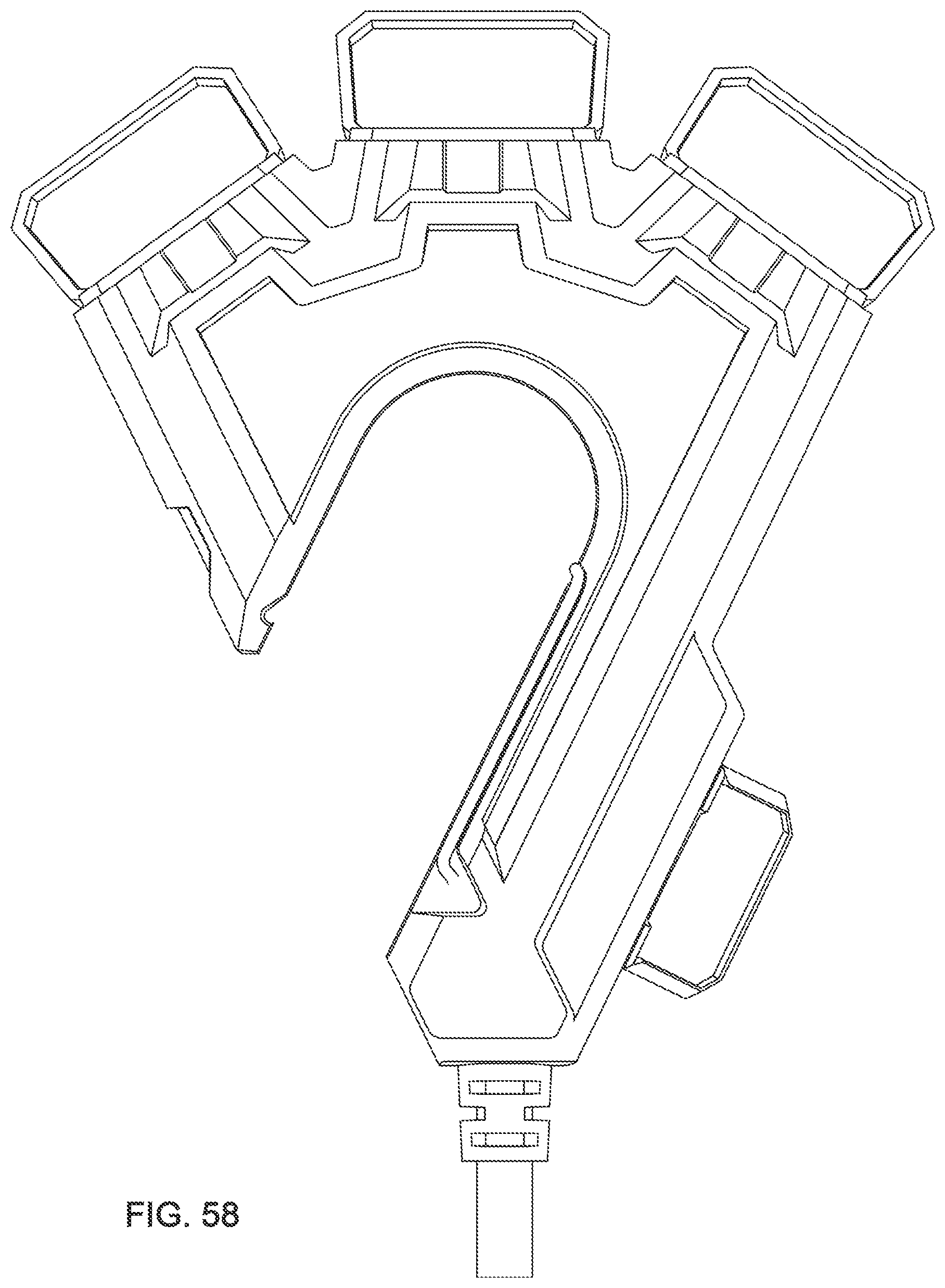
[0066] FIG. 58 is a bottom view of a second embodiment depicted with a gate and doors open.
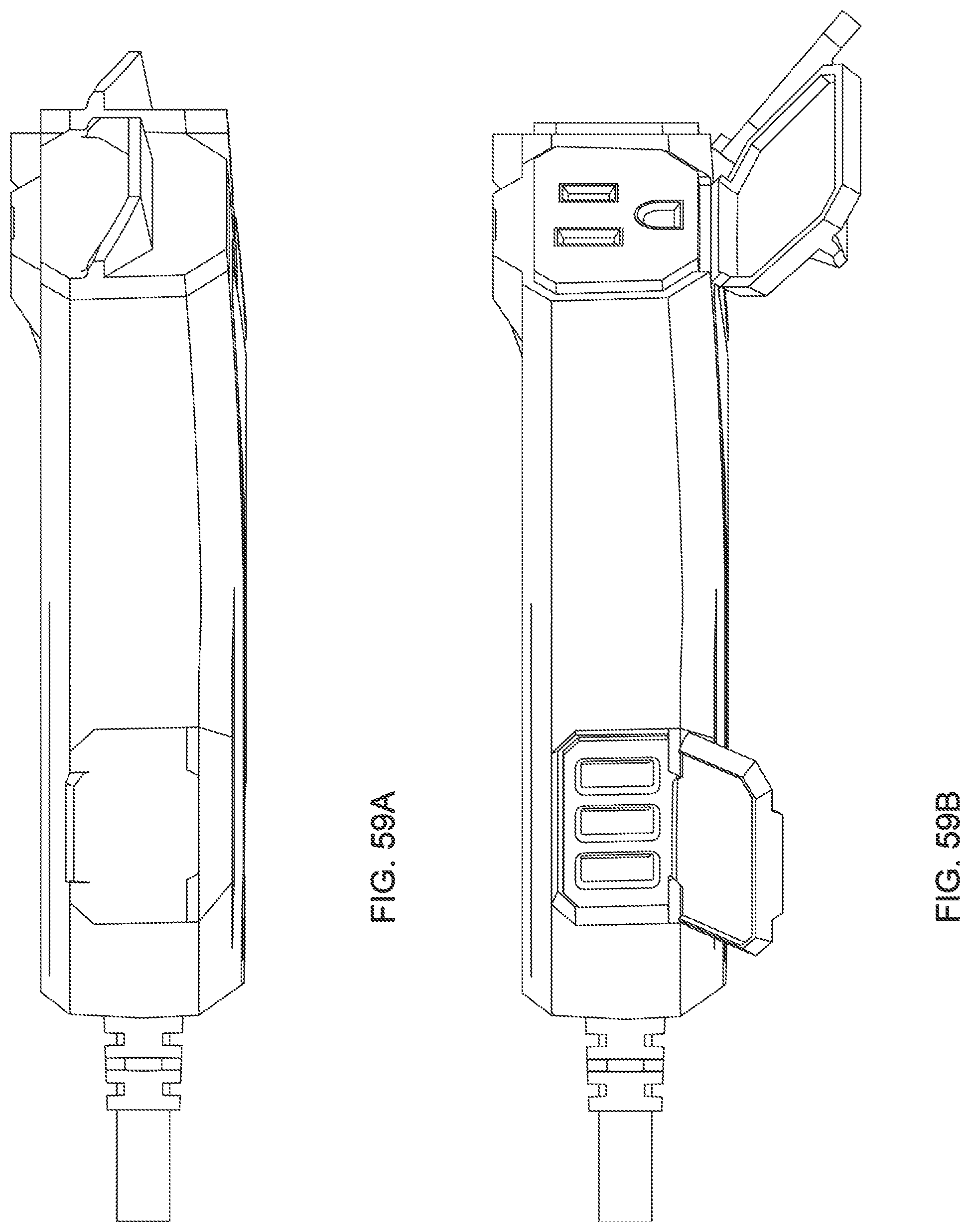
[0067] FIG. 59A is a side view of a second embodiment depicted with a gate and doors closed.
[0068] FIG. 59B is a side view of a second embodiment depicted with a gate and doors open.
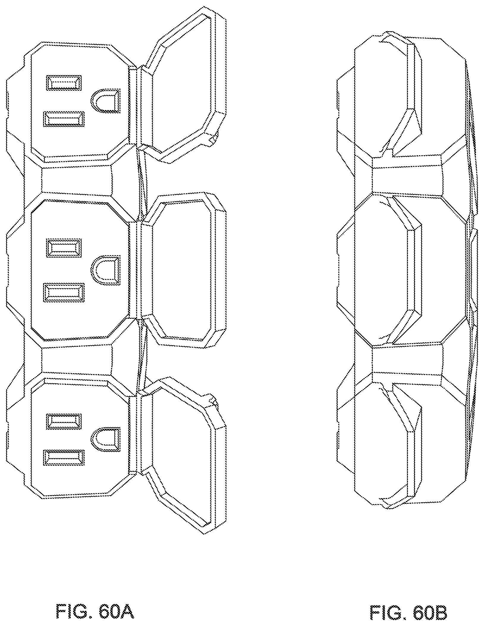
[0069] FIG. 60A is a front view of a second embodiment depicted with a gate and doors open.
[0070] FIG. 60B is a front view of a second embodiment depicted with a gate and doors closed.
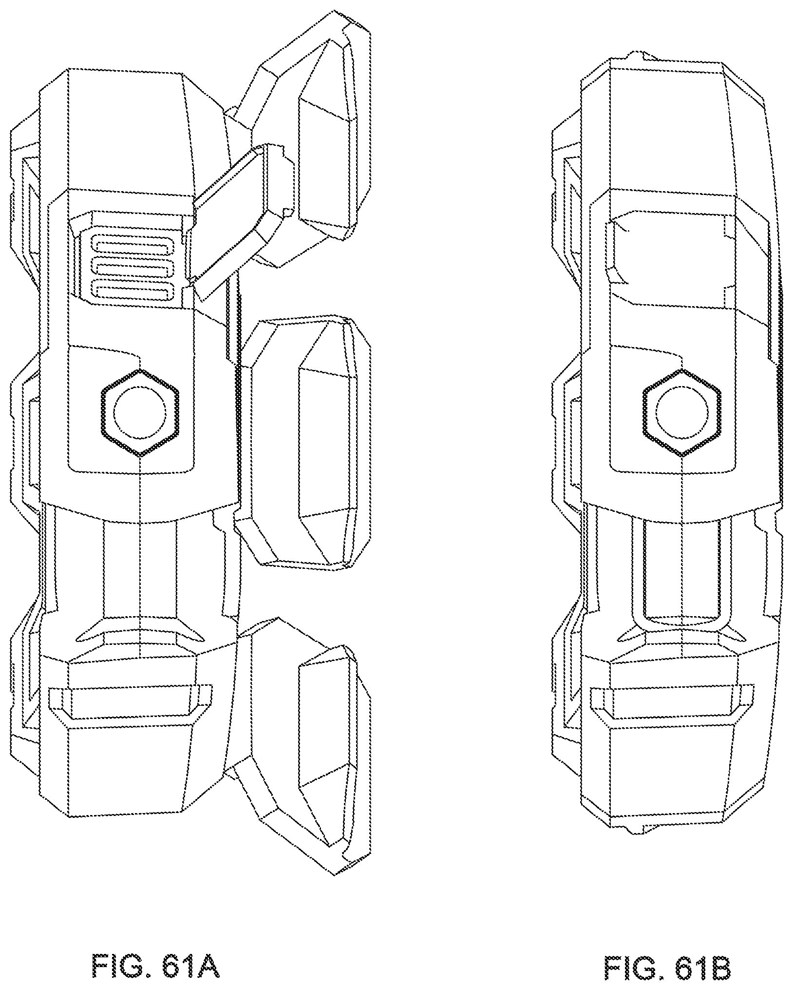
[0071] FIG. 61A is a back view of a second embodiment depicted with a gate and doors open.
[0072] FIG. 61B is a back view of a second embodiment depicted with a gate and doors closed.
[0073] FIG. 62 is a perspective view of a second embodiment depicted with a gate and doors closed.
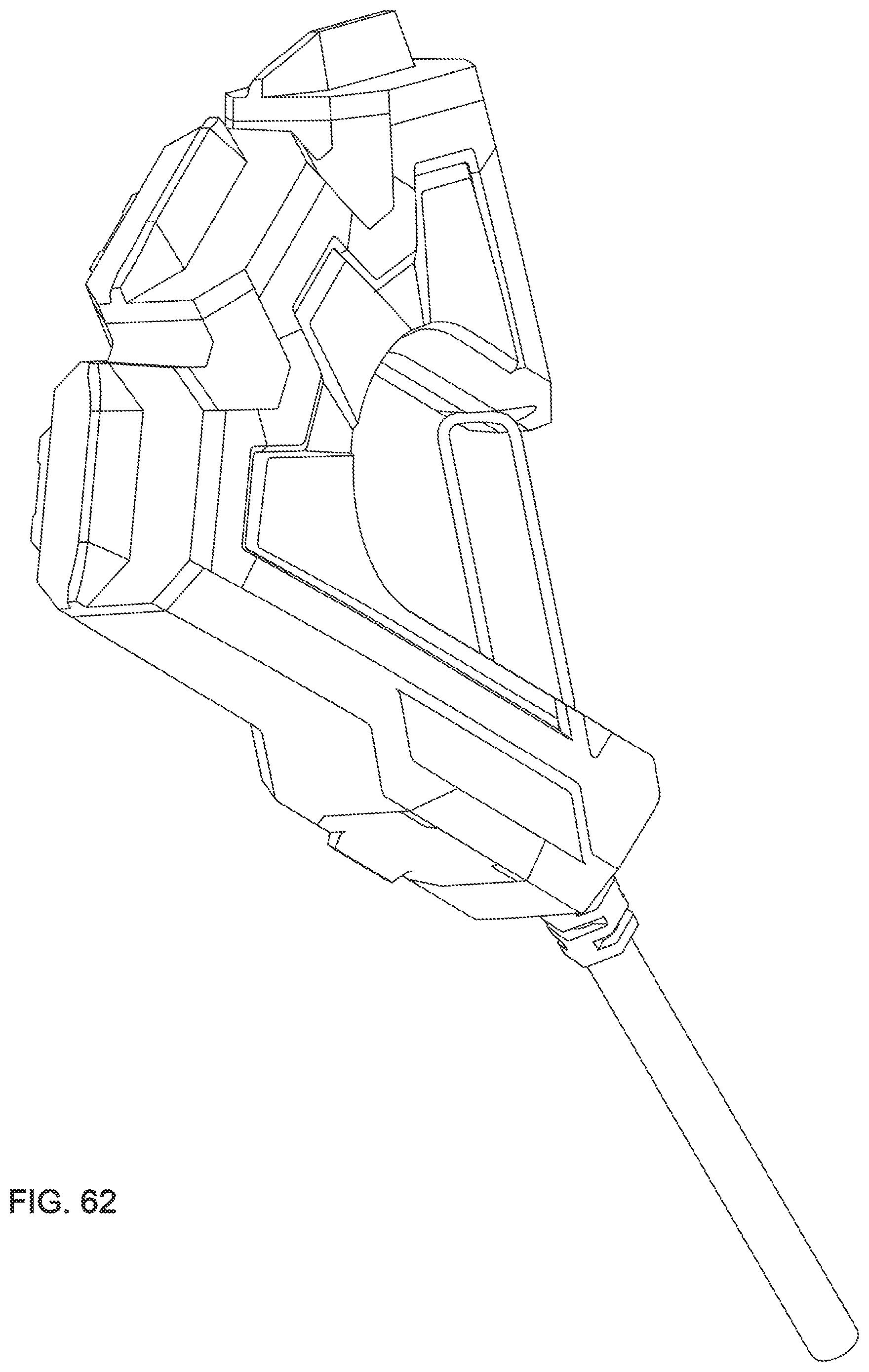
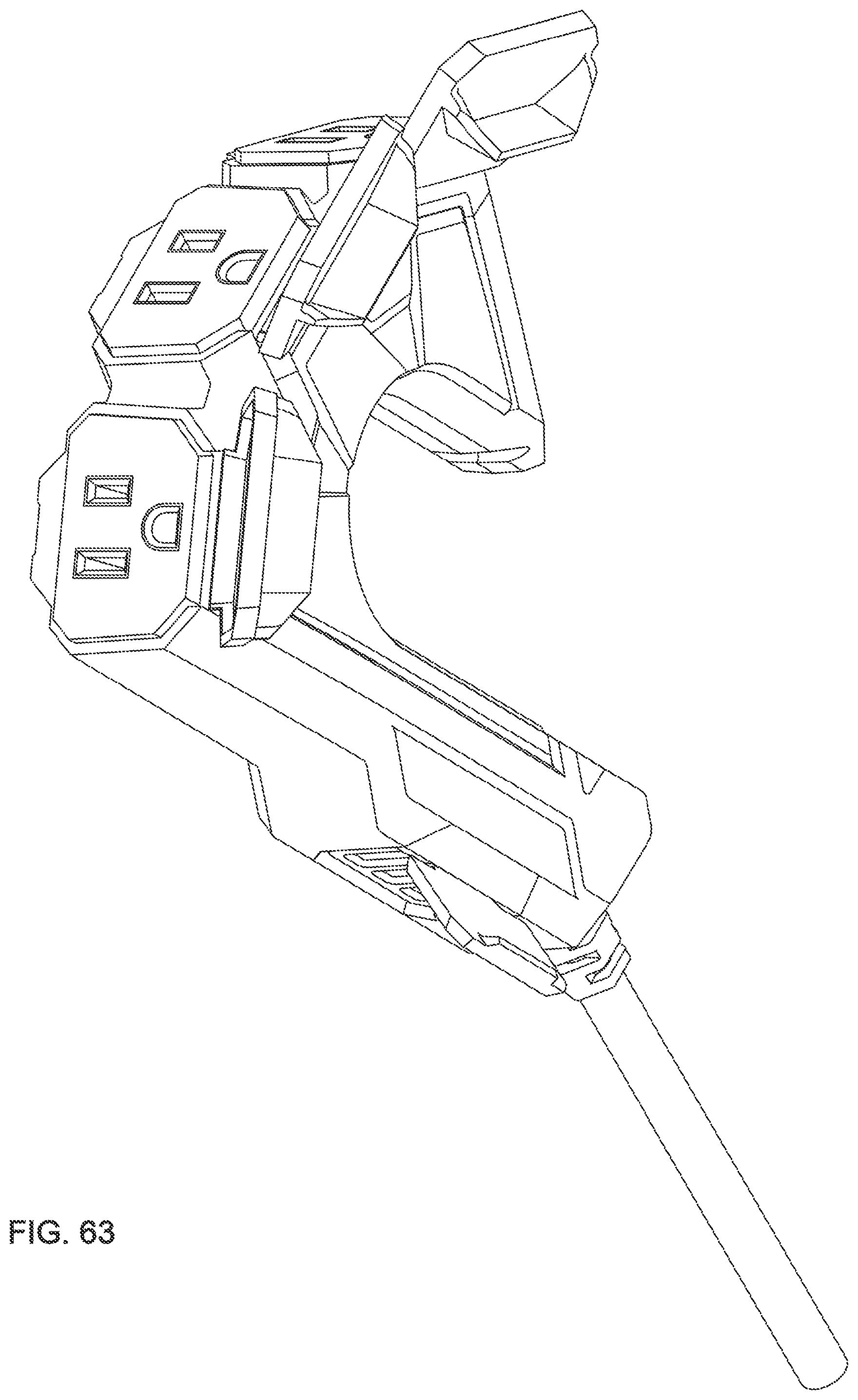
[0074] FIG. 63 is a perspective view of a second embodiment depicted with a gate and doors open.
[0075] FIG. 64 is a perspective view of a second embodiment depicted with a gate and doors closed.
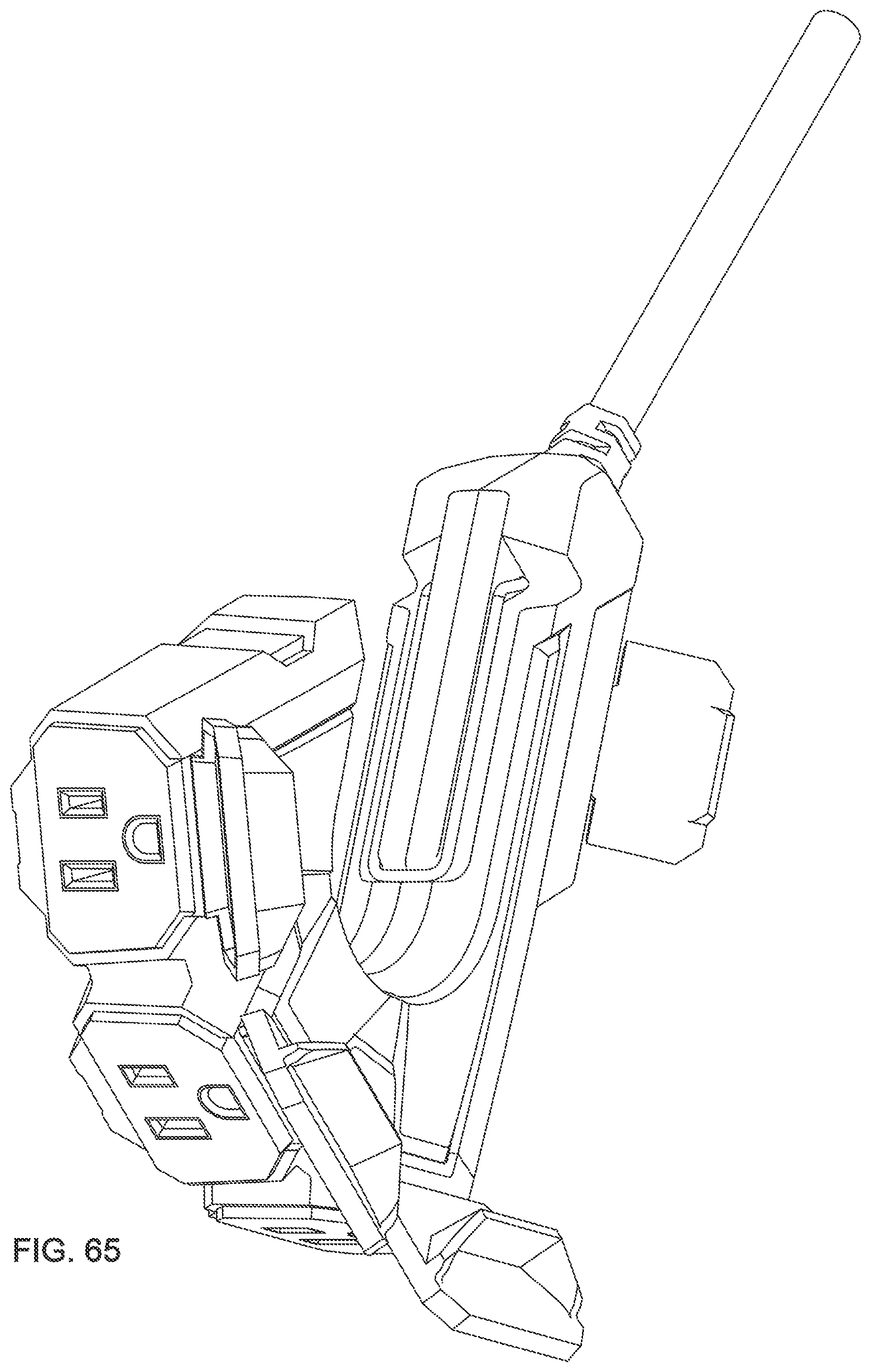
[0076] FIG. 65 is a perspective view of a second embodiment depicted with a gate and doors open.
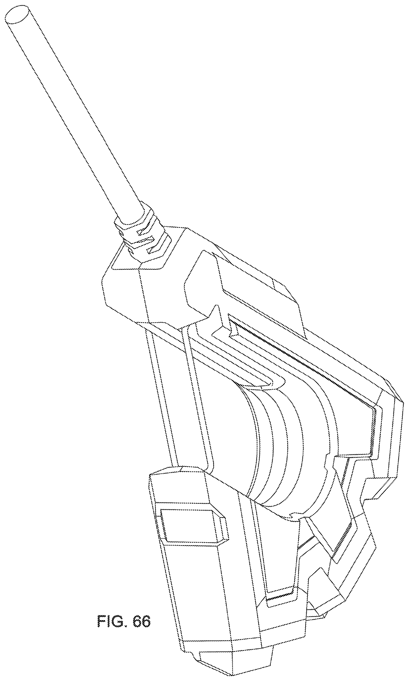
[0077] FIG. 66 is a perspective view of a second embodiment depicted with a gate and doors closed.
[0078] FIG. 67 is a perspective view of a second embodiment depicted with a gate and doors open.
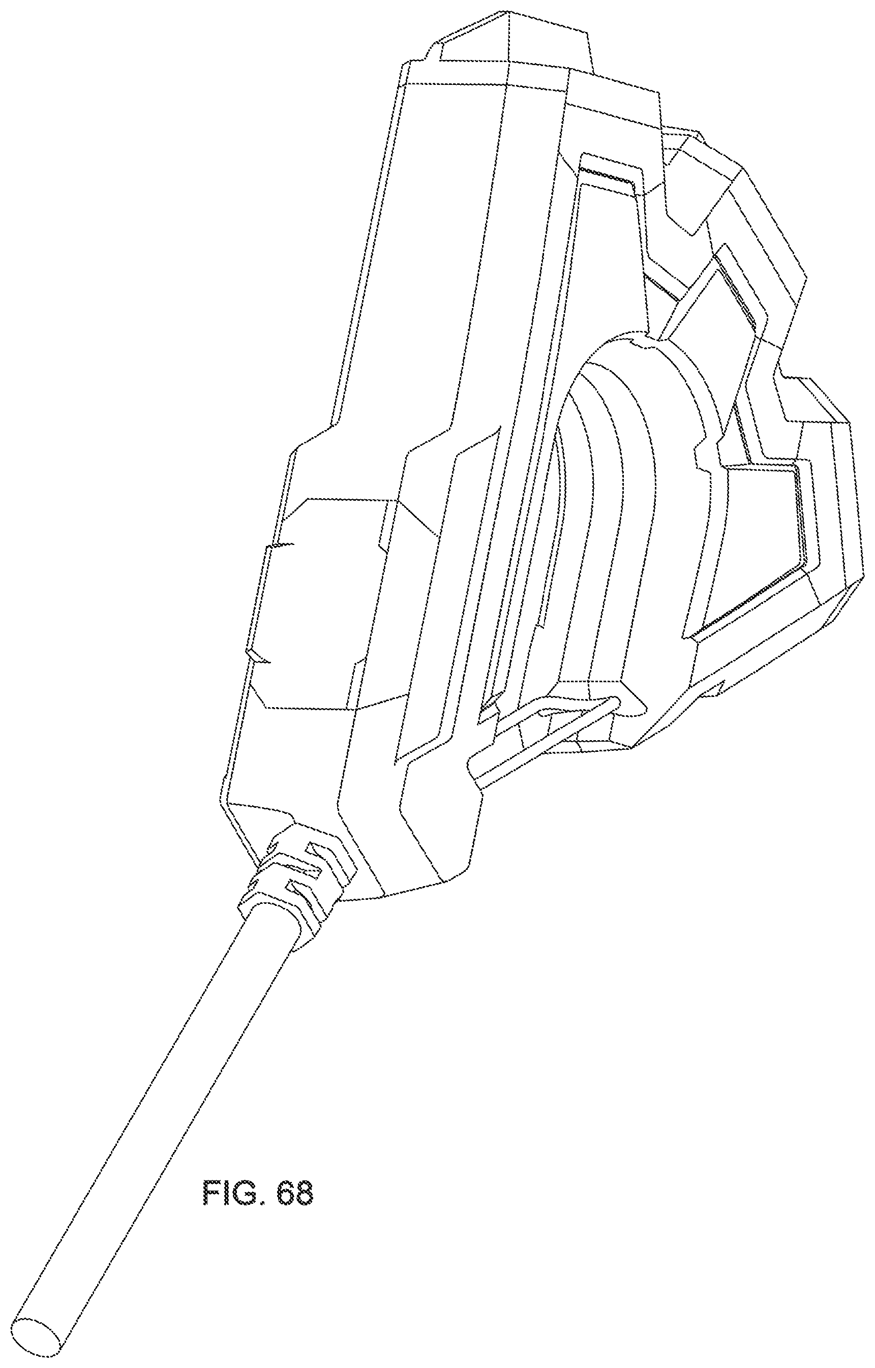
[0079] FIG. 68 is a perspective view of a second embodiment depicted with a gate and doors closed.
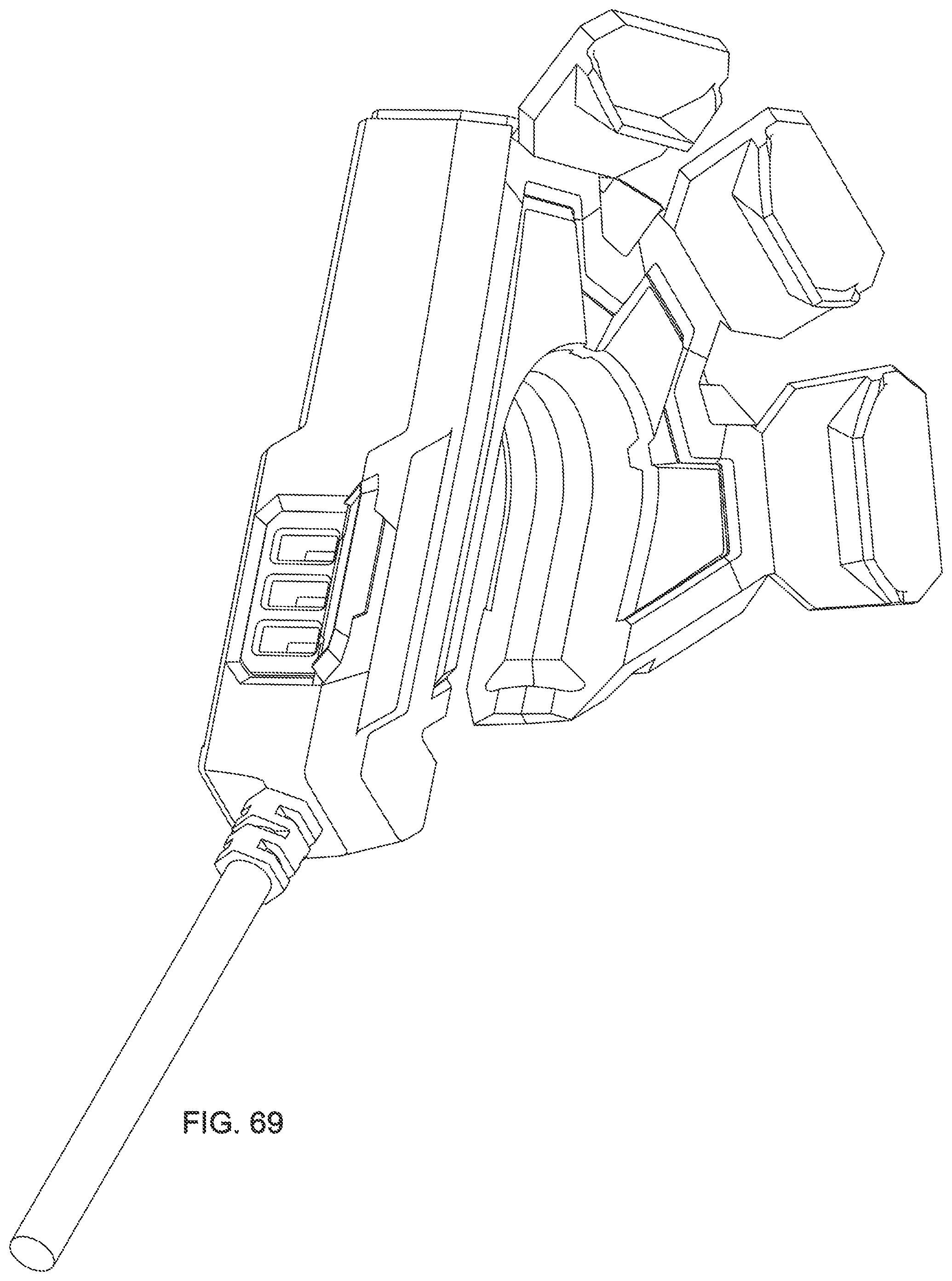
[0080] FIG. 69 is a perspective view of a second embodiment depicted with a gate and doors open.
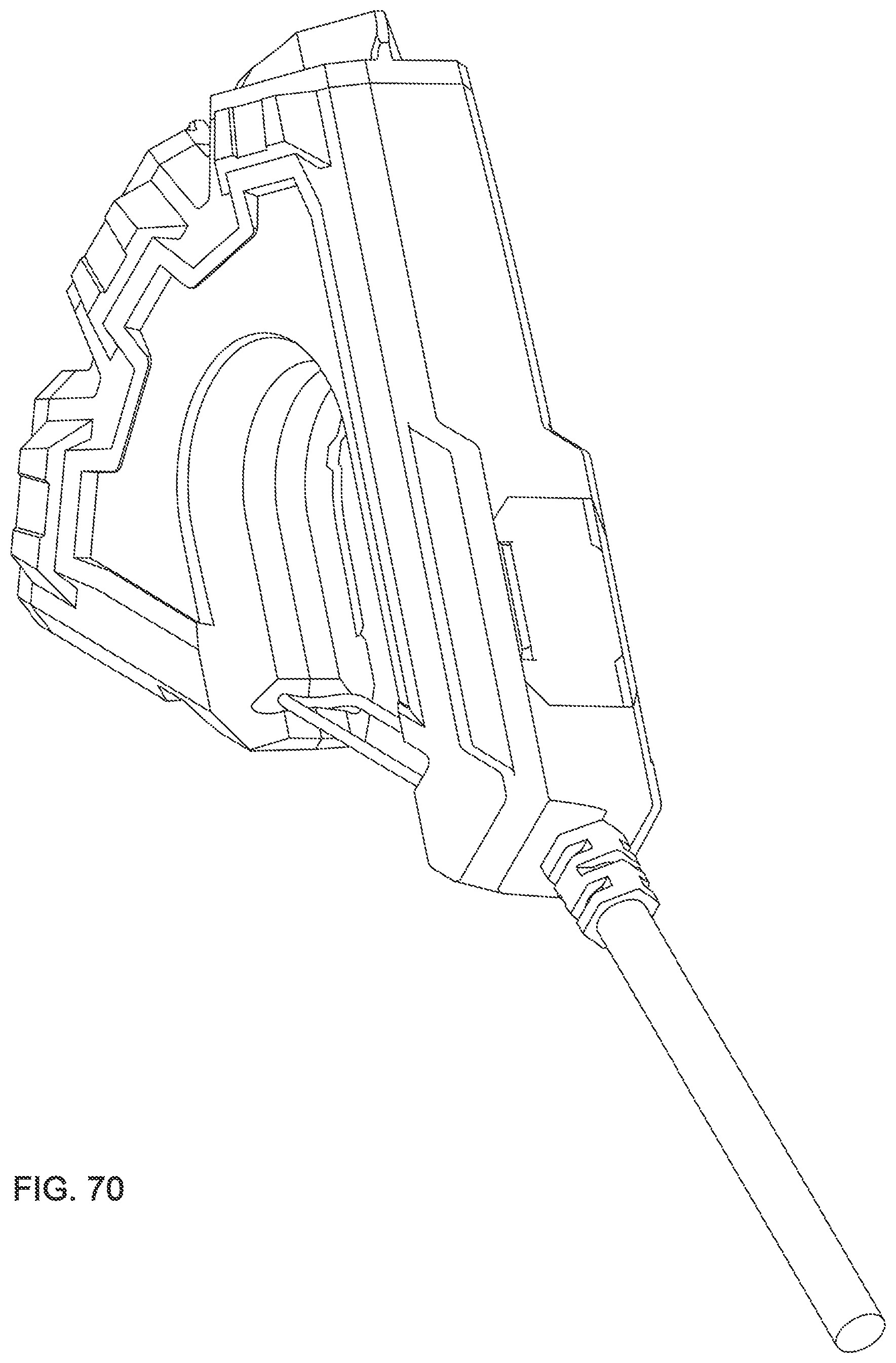
[0081] FIG. 70 is a perspective view of a second embodiment depicted with a gate and doors closed.
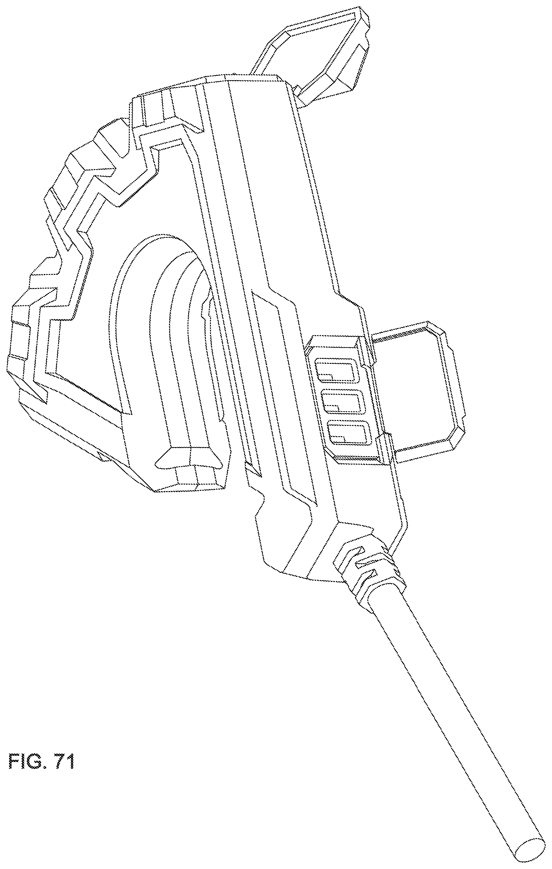
[0082] FIG. 71 is a perspective view of a second embodiment depicted with a gate and doors open.
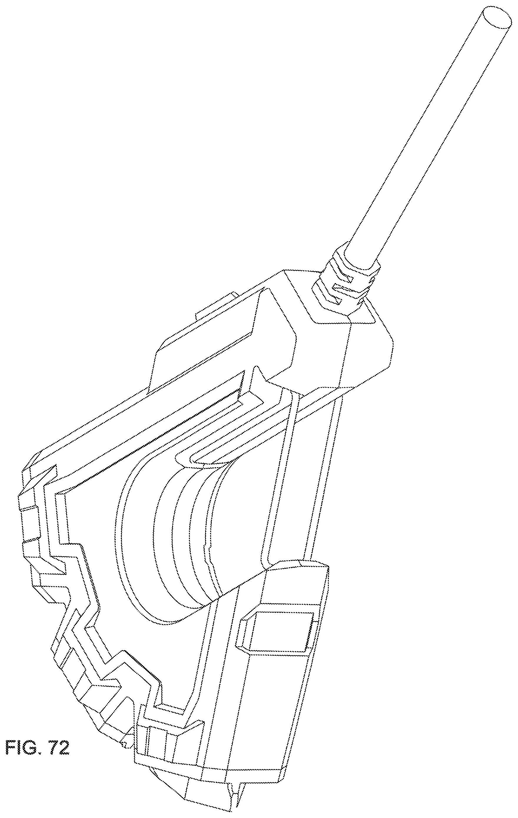
[0083] FIG. 72 is a perspective view of a second embodiment depicted with a gate and doors closed.
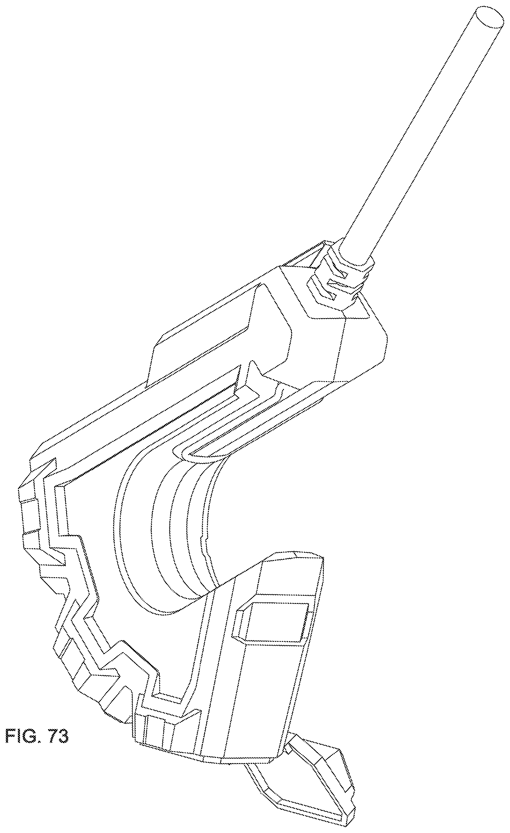
[0084] FIG. 73 is a perspective view of a second embodiment depicted with a gate and doors open.
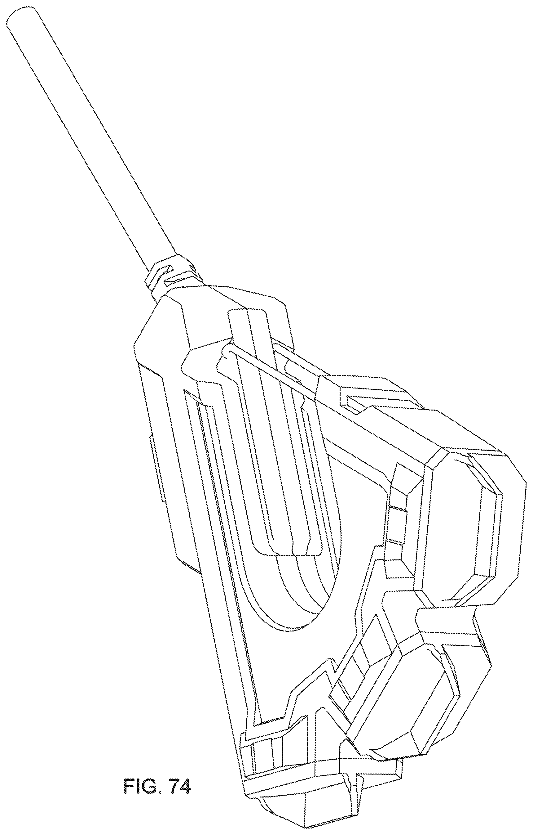
[0085] FIG. 74 is a perspective view of a second embodiment depicted with a gate and doors closed.
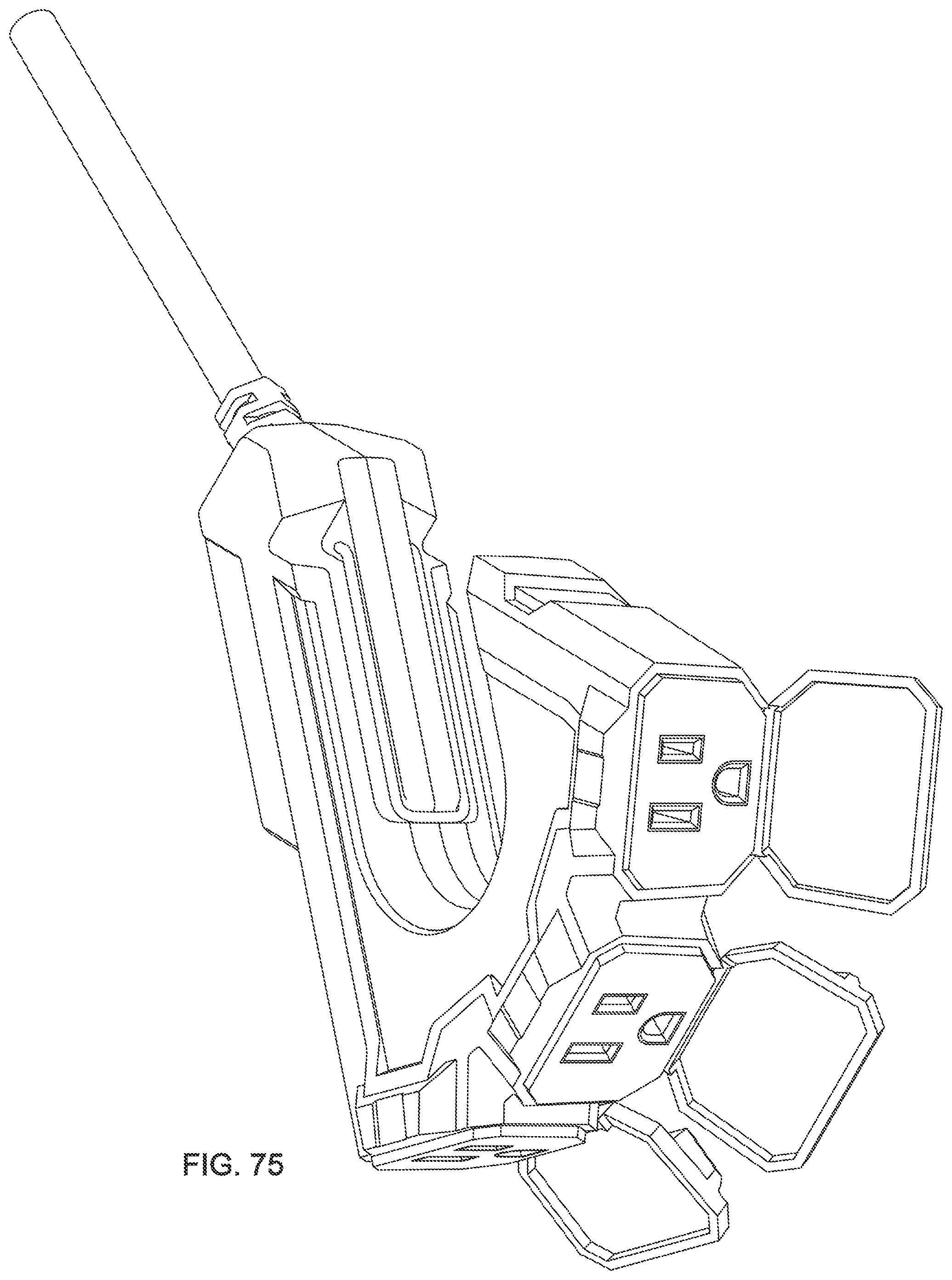
[0086] FIG. 75 is a perspective view of a second embodiment depicted with a gate and doors open.
[0087] FIG. 76 is a perspective view of a second embodiment depicted with a gate and doors closed.
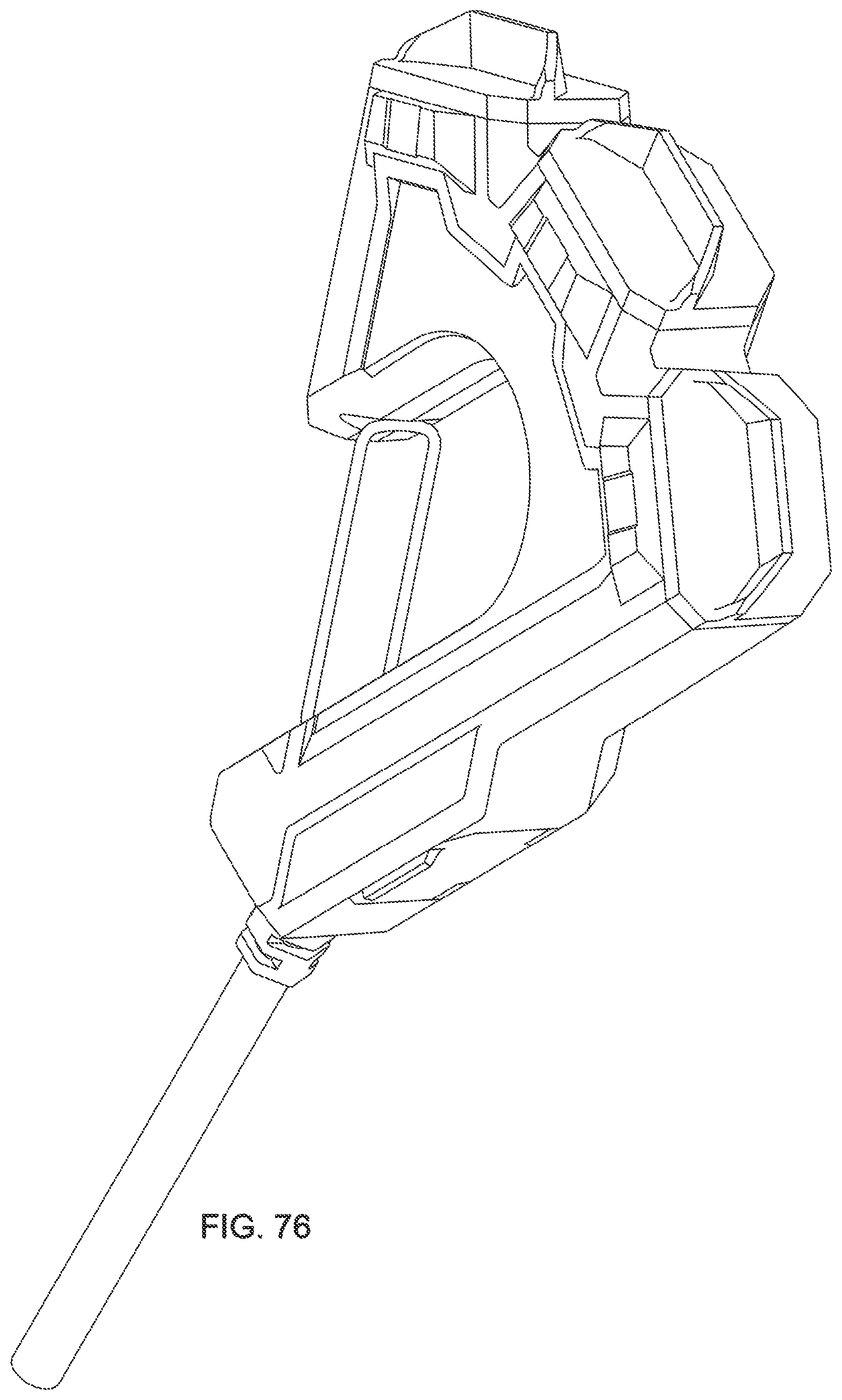
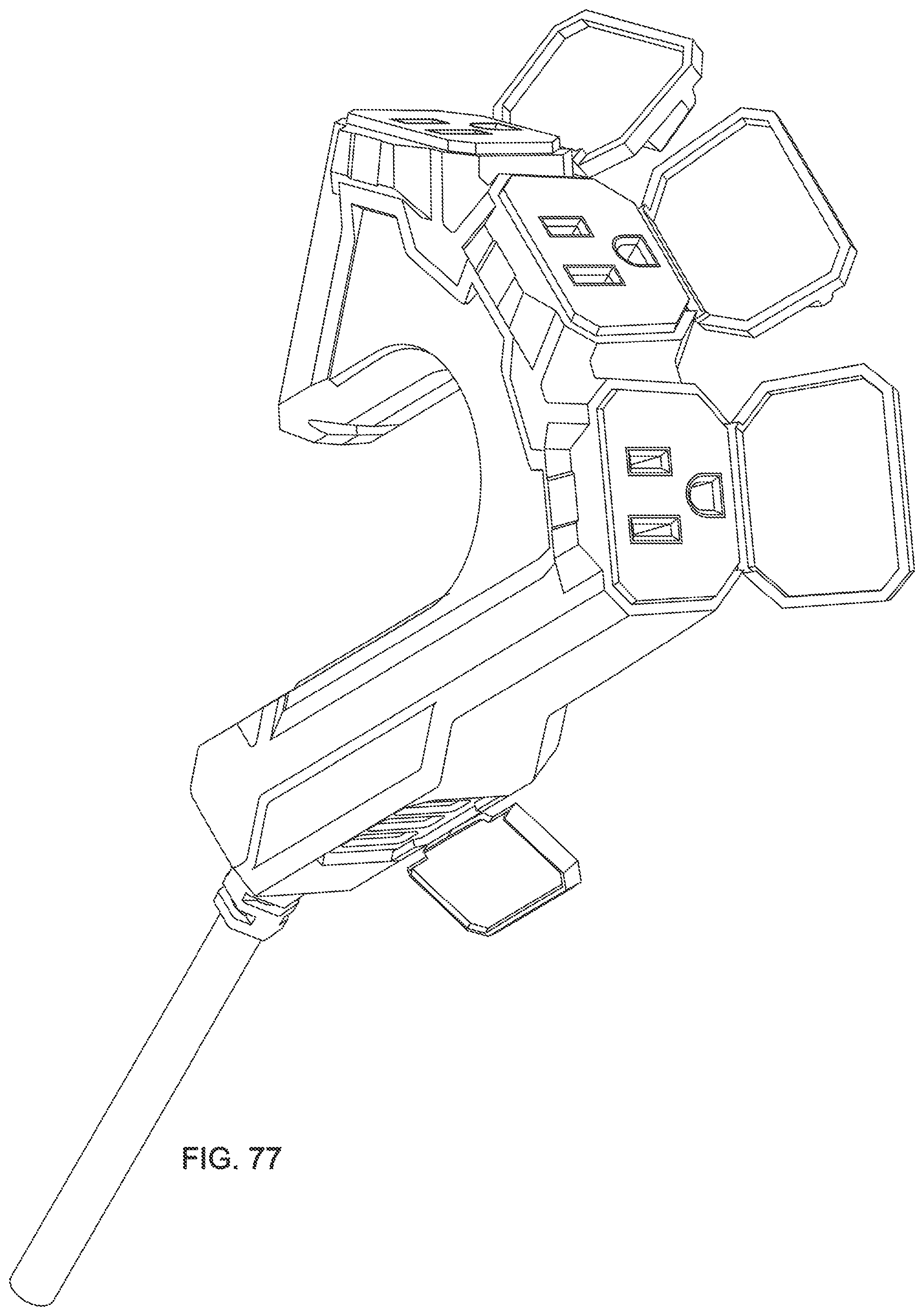
[0088] FIG. 77 is a perspective view of a second embodiment depicted with a gate and doors open.
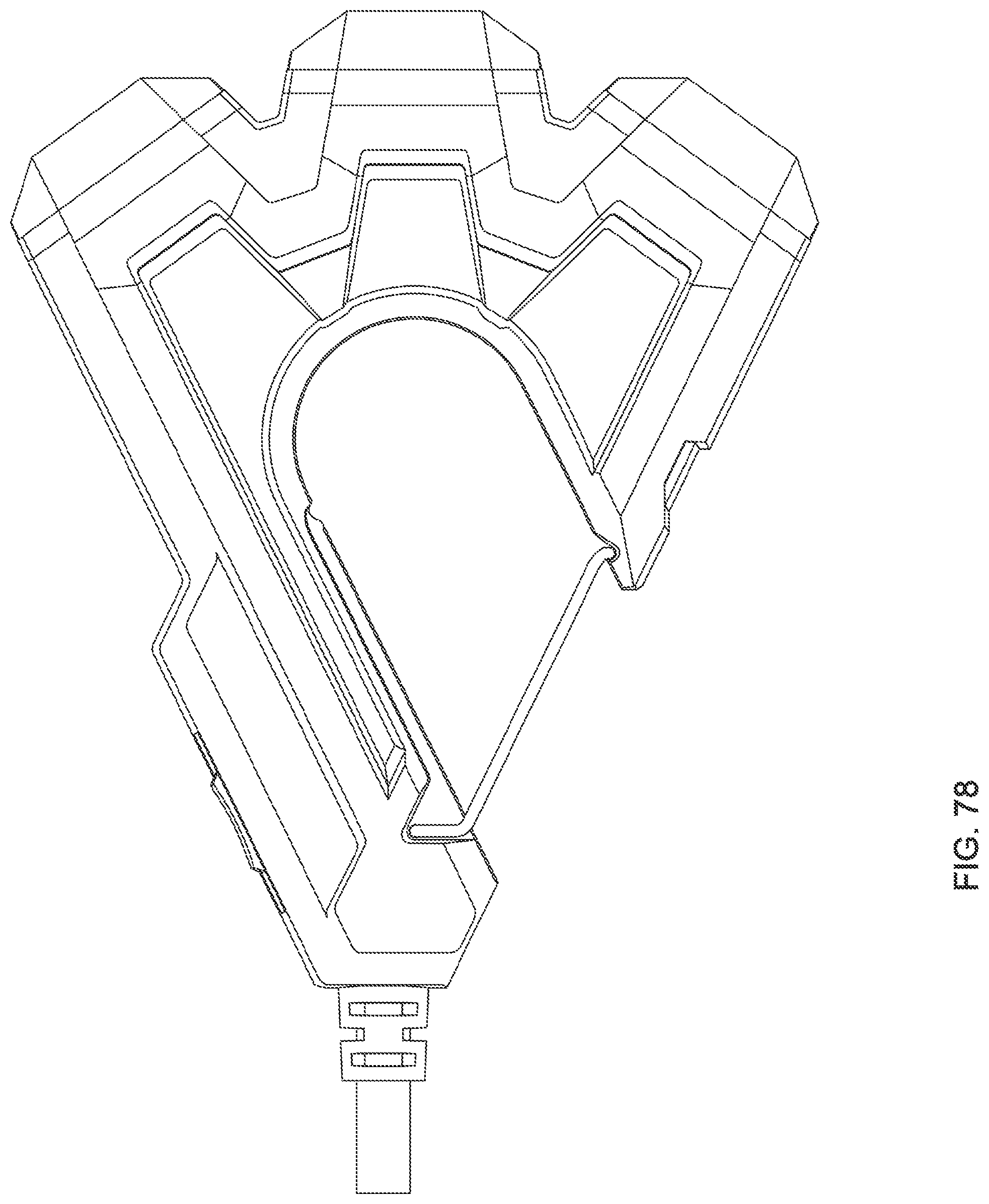
[0089] FIG. 78 is a top view of a third embodiment depicted with a gate and doors closed.
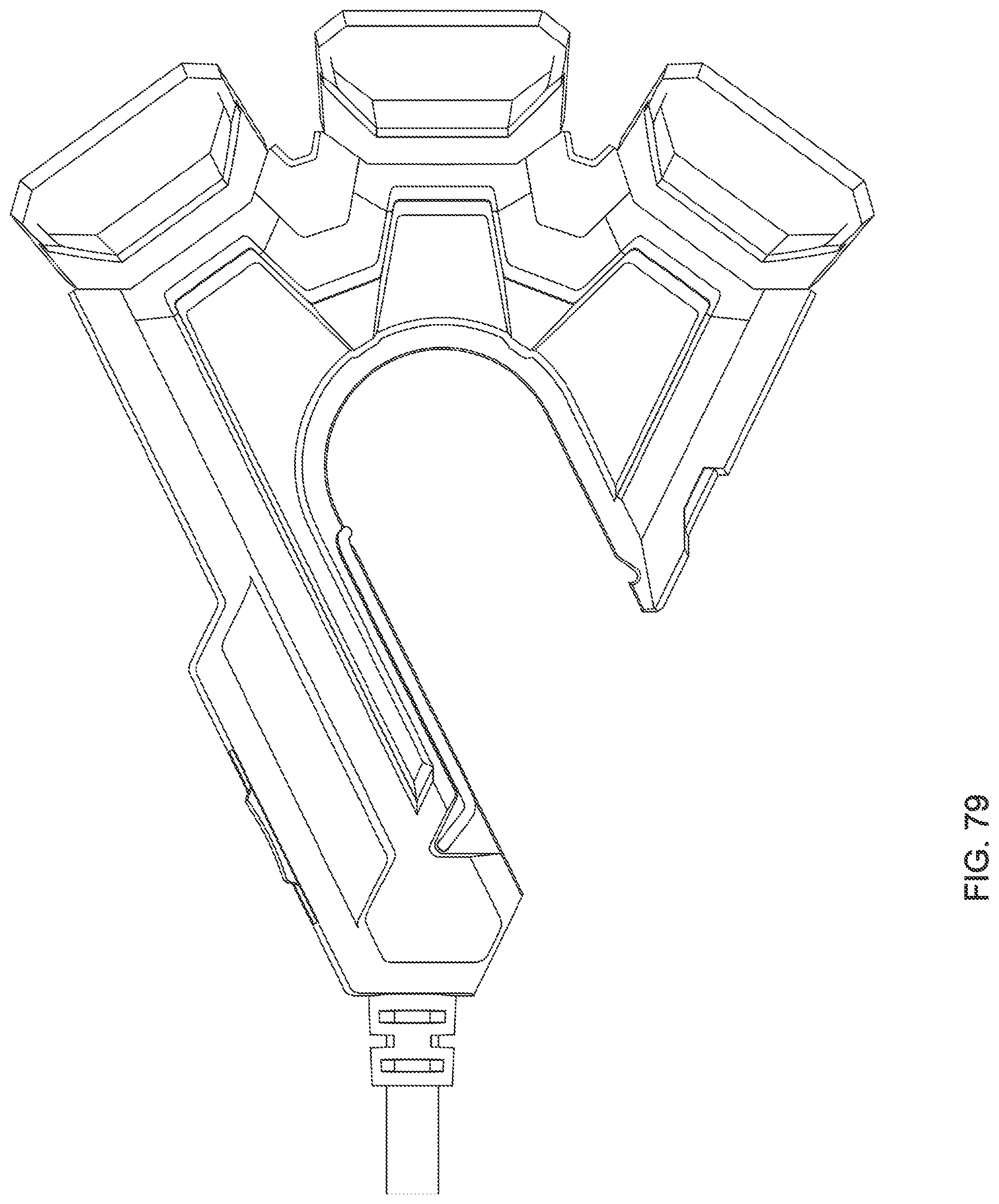
[0090] FIG. 79 is a top view of a third embodiment depicted with a gate and doors open.
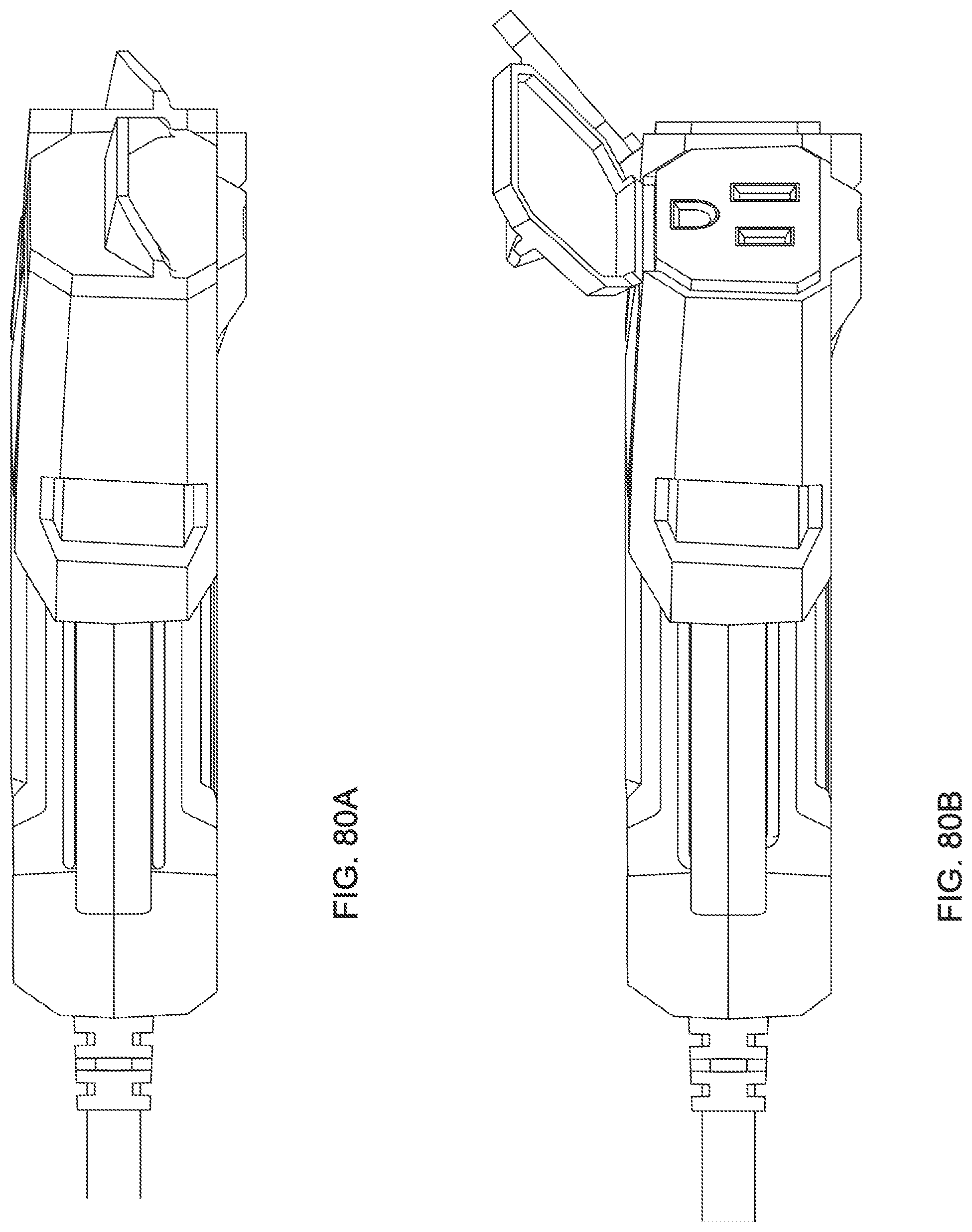
[0091] FIG. 80A is a side view of a third embodiment depicted with a gate and doors closed.
[0092] FIG. 80B is a side view of a third embodiment depicted with a gate and doors open.
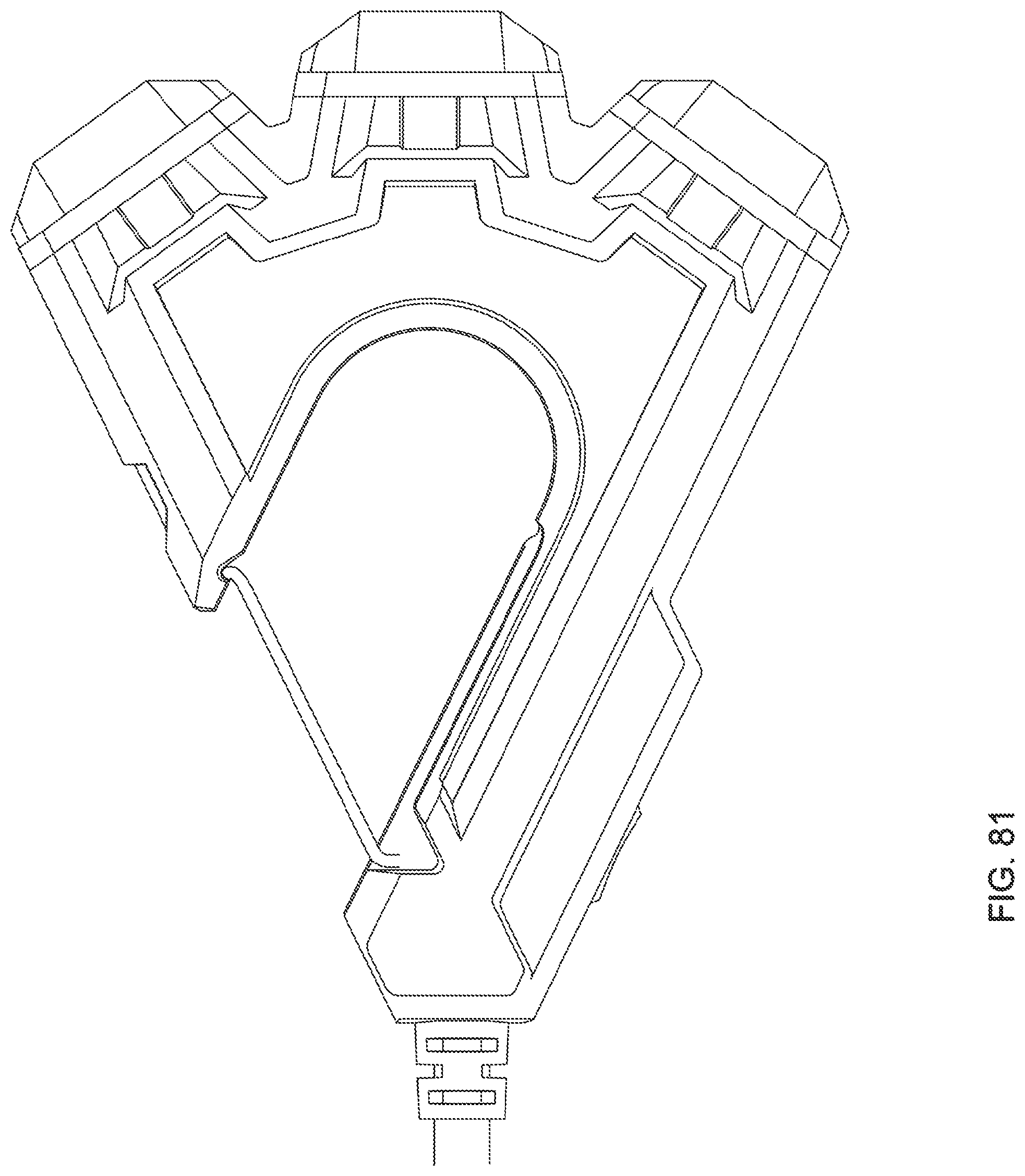
[0093] FIG. 81 is a bottom view of a third embodiment depicted with a gate and doors closed.
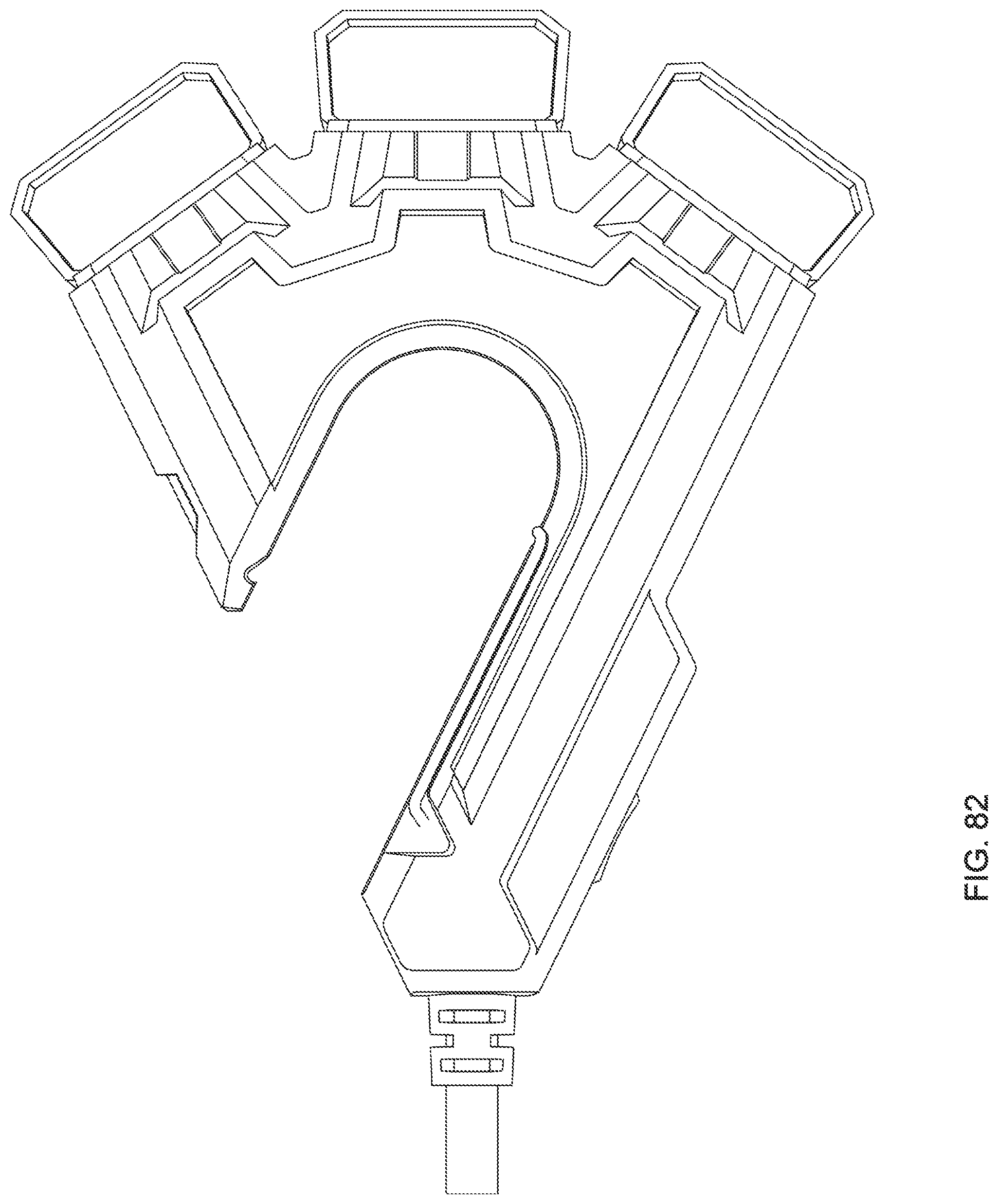
[0094] FIG. 82 is a bottom view of a third embodiment depicted with a gate and doors open.
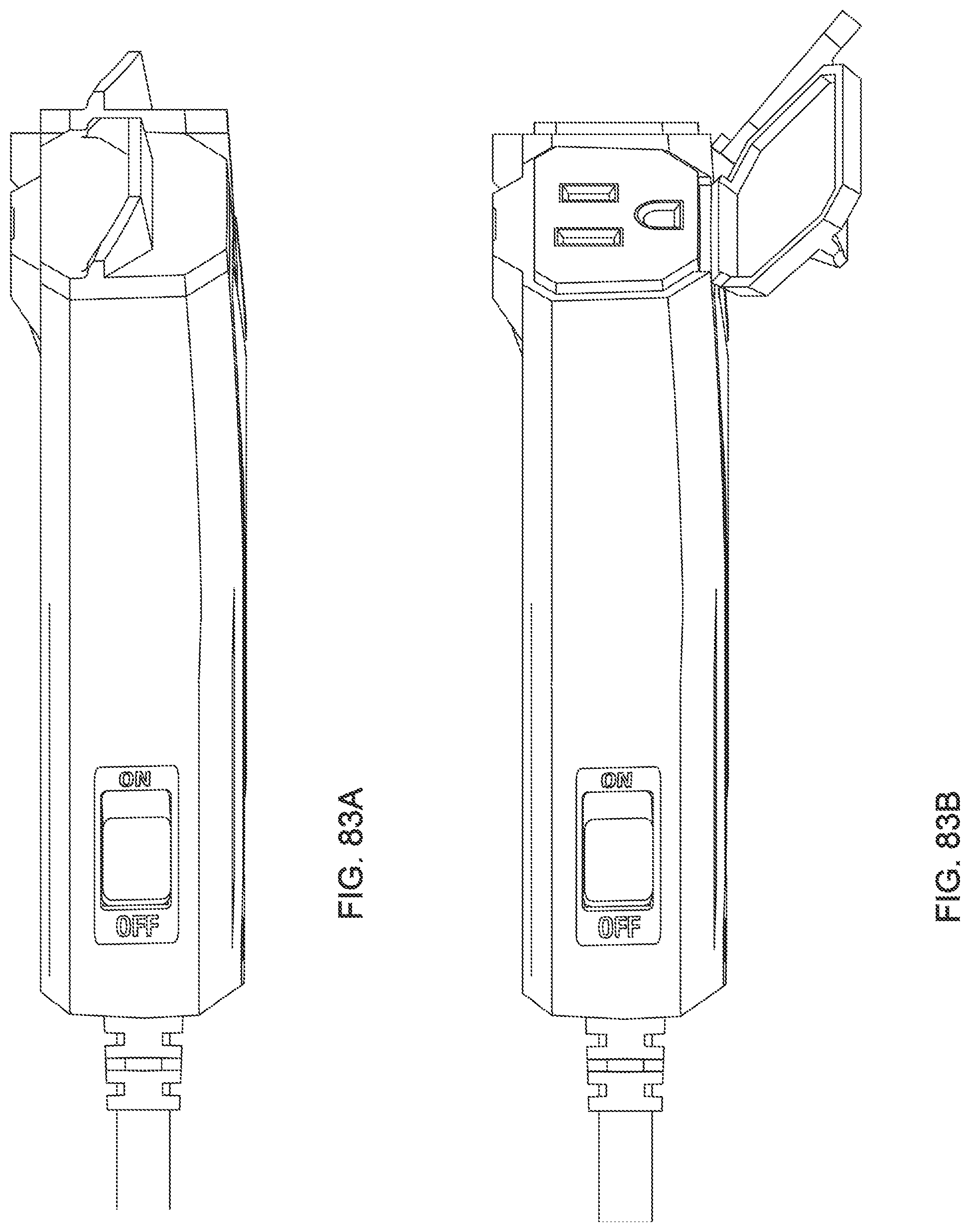
[0095] FIG. 83A is a side view of a third embodiment depicted with a gate and doors closed.
[0096] FIG. 83B is a side view of a third embodiment depicted with a gate and doors open.
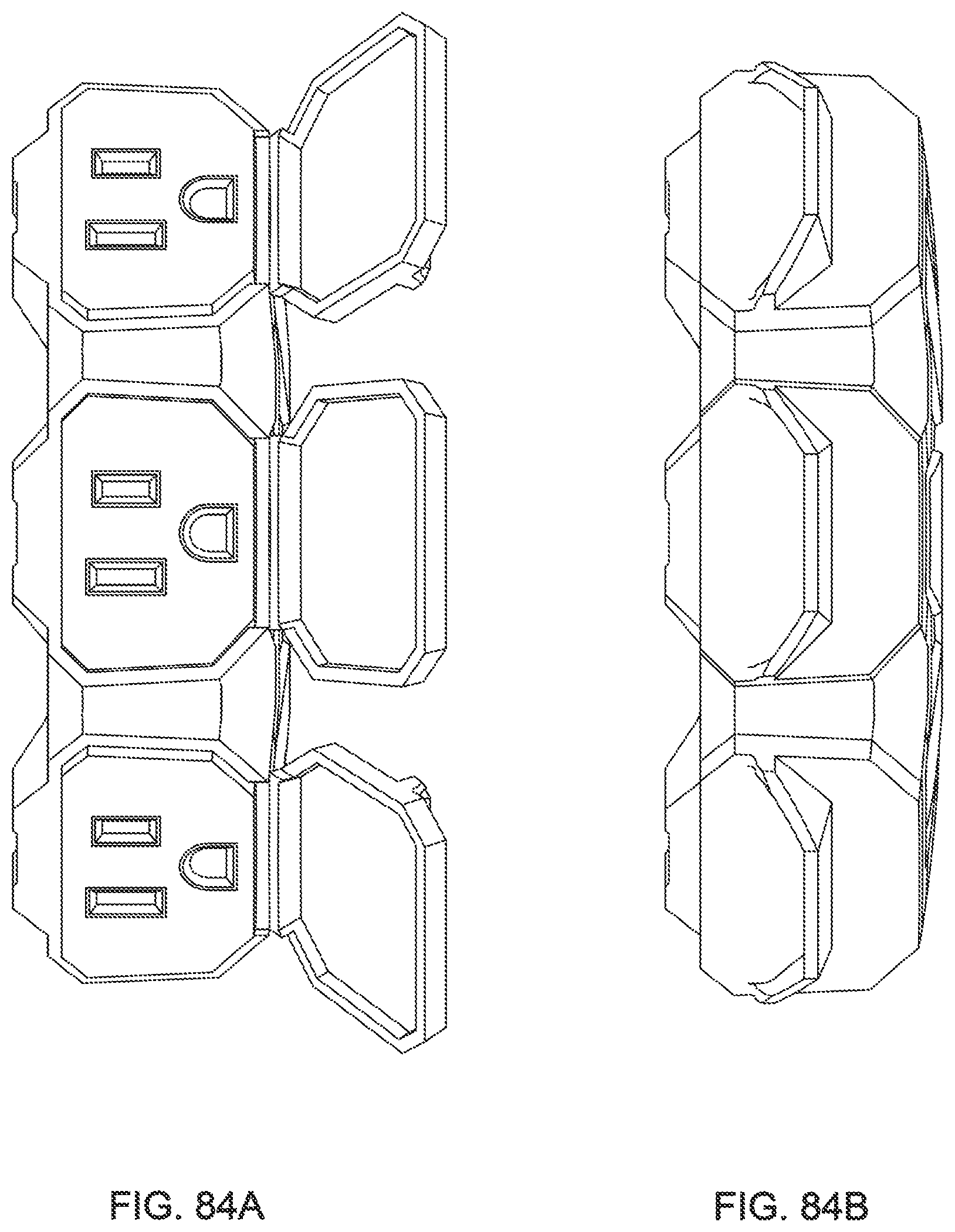
[0097] FIG. 84A is a front view of a third embodiment depicted with a gate and doors open.
[0098] FIG. 84B is a front view of a third embodiment depicted with a gate and doors closed.
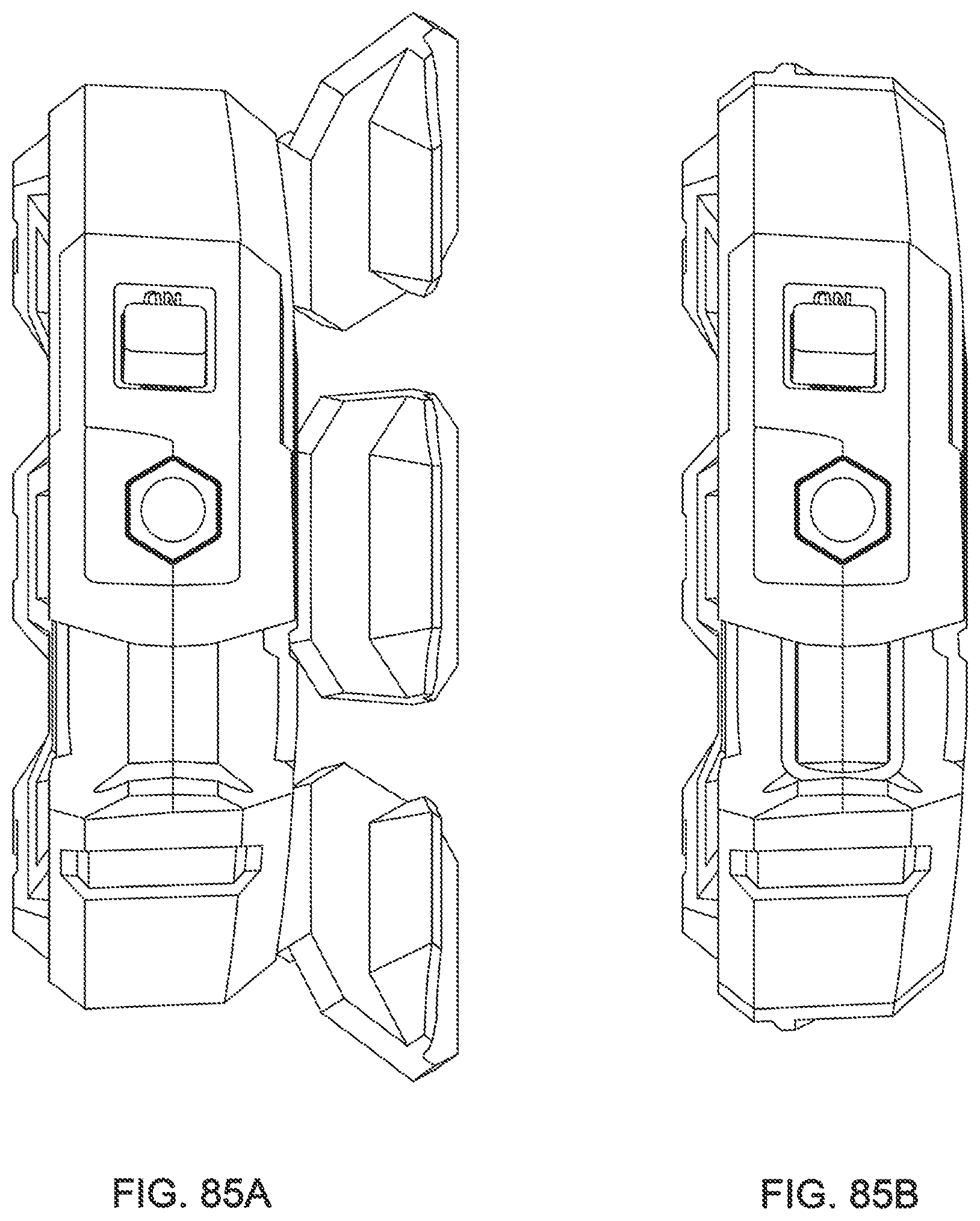
[0099] FIG. 85A is a back view of a third embodiment depicted with a gate and doors open.
[0100] FIG. 85B is a back view of a third embodiment depicted with a gate and doors closed.
[0101] FIG. 86 is a perspective view of a third embodiment depicted with a gate and doors closed.
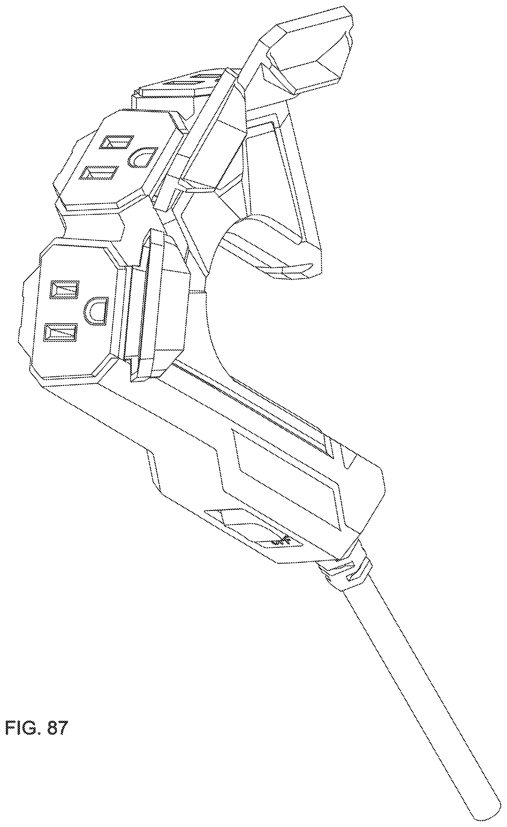
[0102] FIG. 87 is a perspective view of a third embodiment depicted with a gate and doors open.
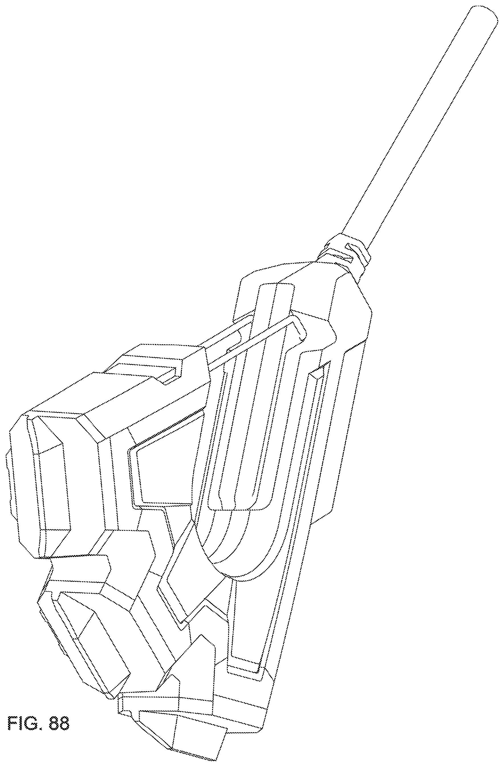
[0103] FIG. 88 is a perspective view of a third embodiment depicted with a gate and doors closed.
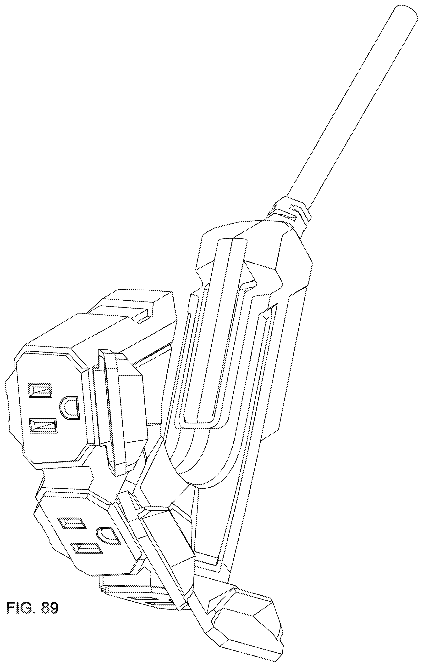
[0104] FIG. 89 is a perspective view of a third embodiment depicted with a gate and doors open.
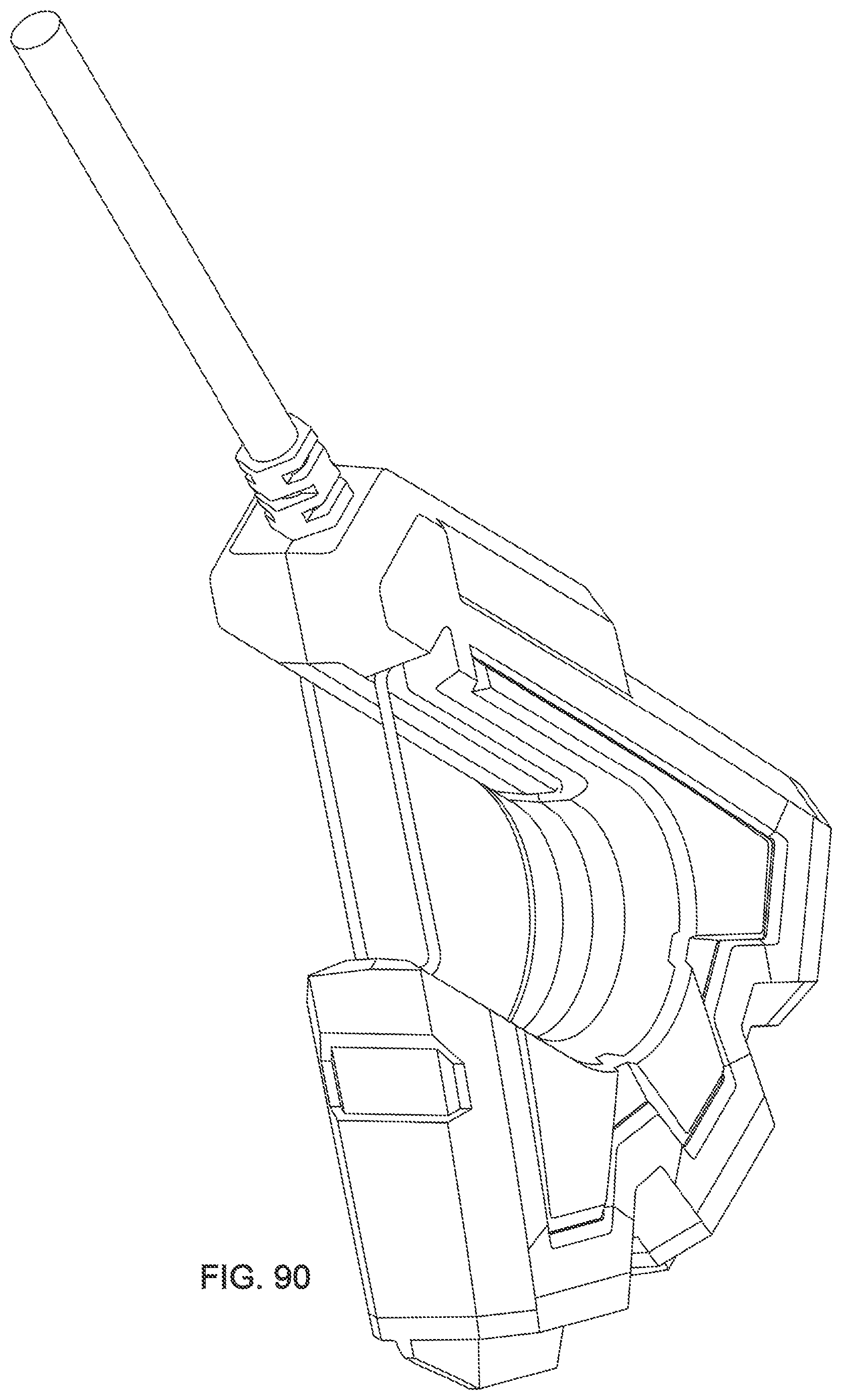
[0105] FIG. 90 is a perspective view of a third embodiment depicted with a gate and doors closed.
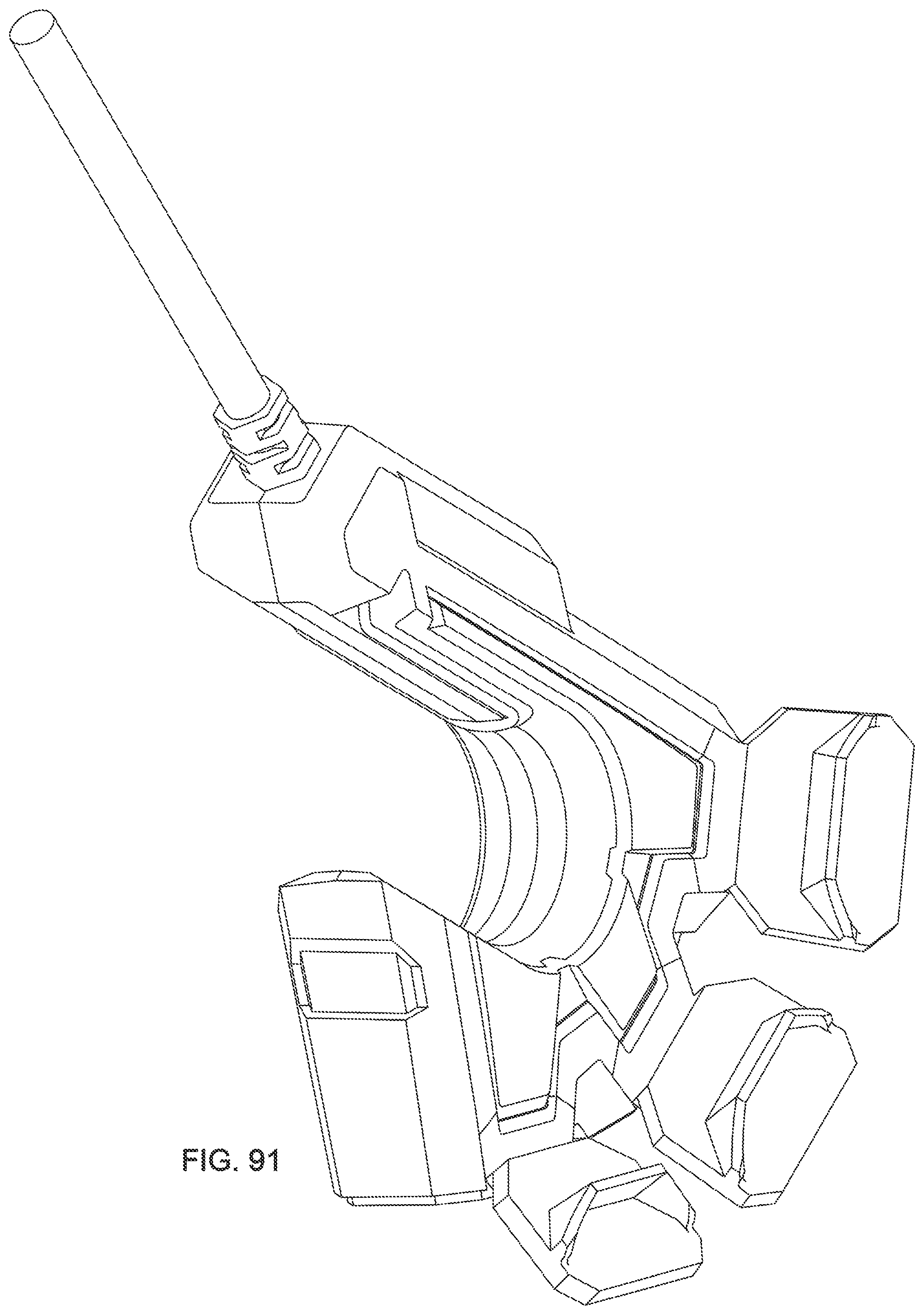
[0106] FIG. 91 is a perspective view of a third embodiment depicted with a gate and doors open.
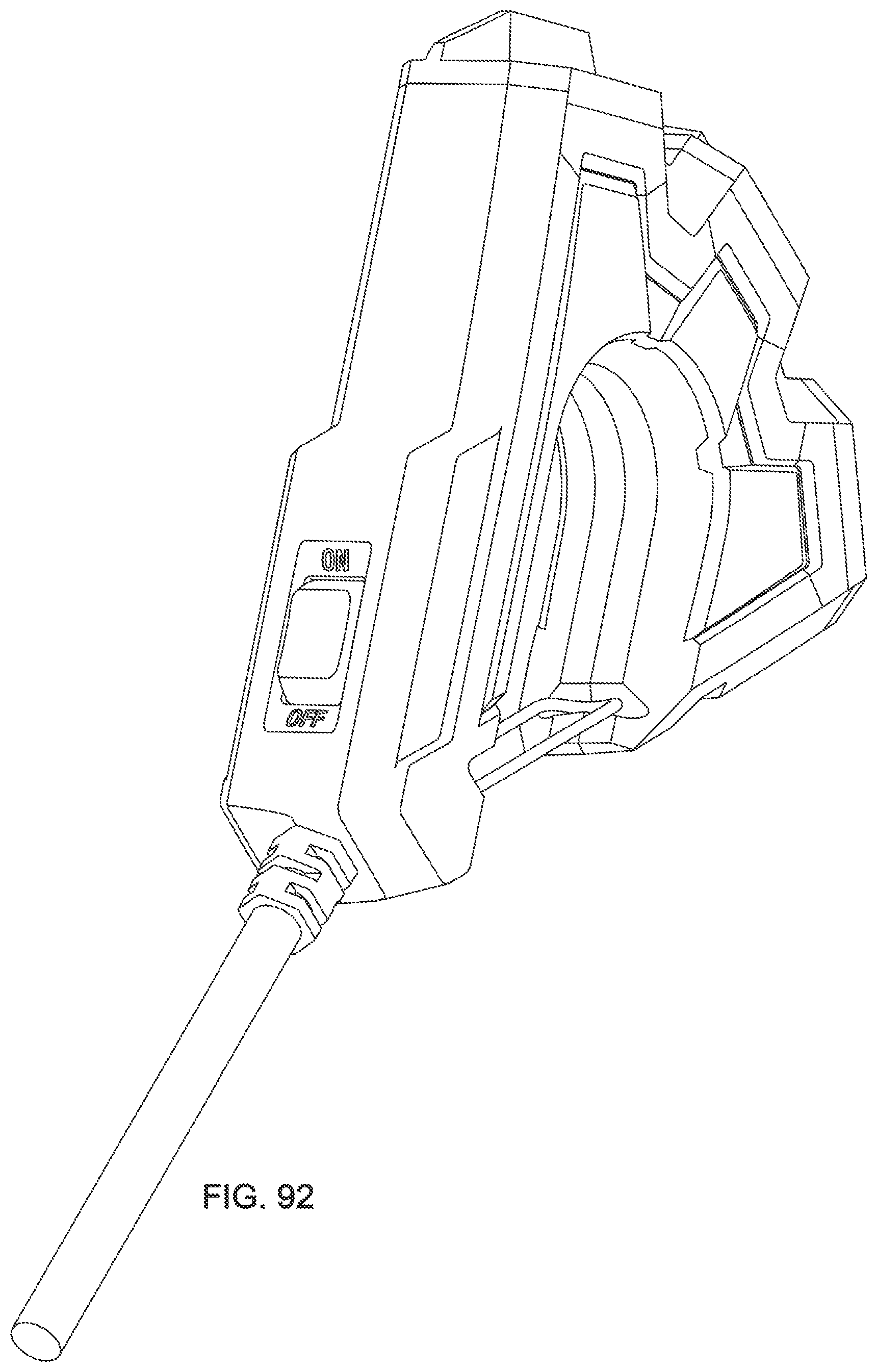
[0107] FIG. 92 is a perspective view of a third embodiment depicted with a gate and doors closed.
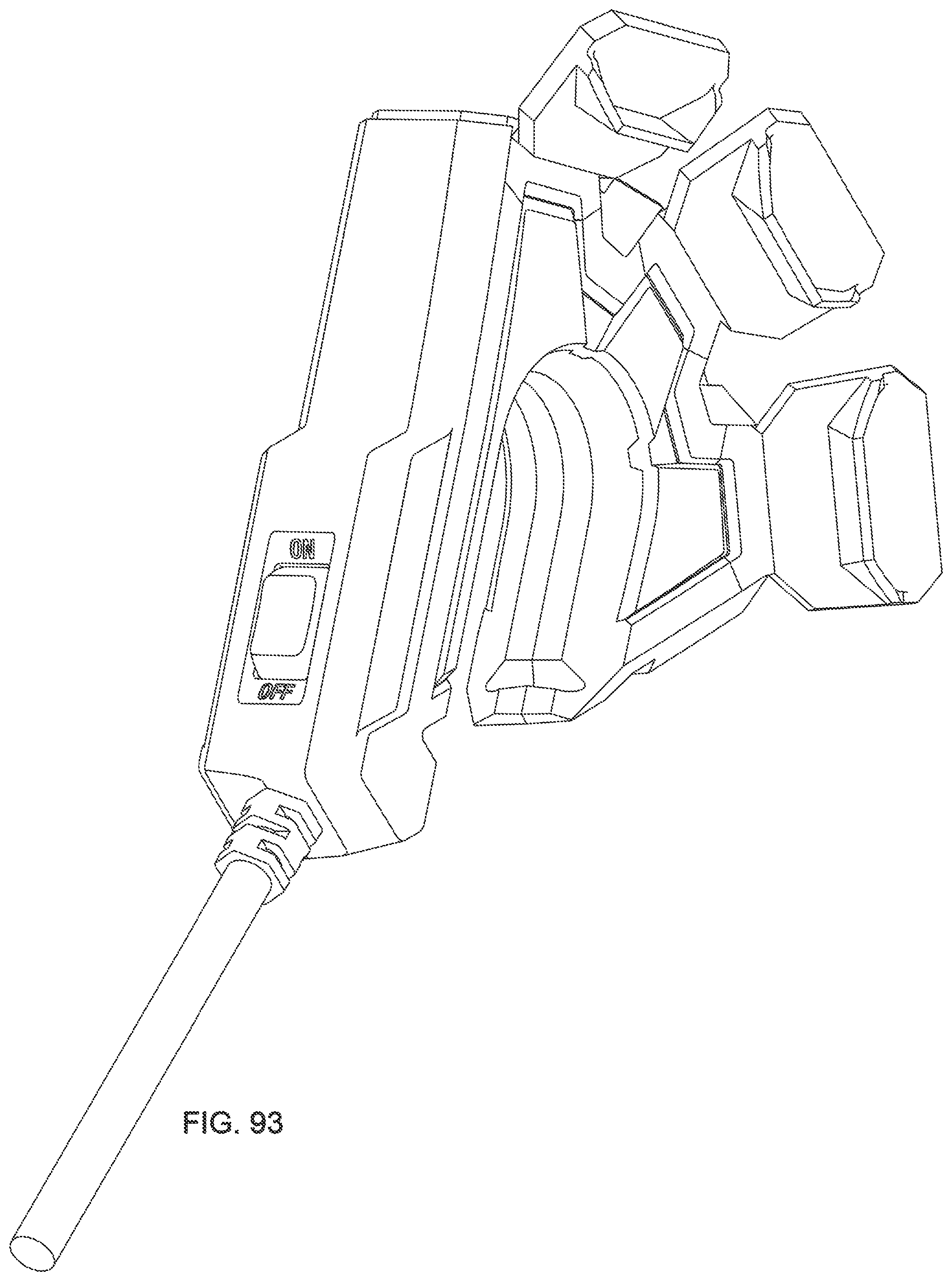
[0108] FIG. 93 is a perspective view of a third embodiment depicted with a gate and doors open.
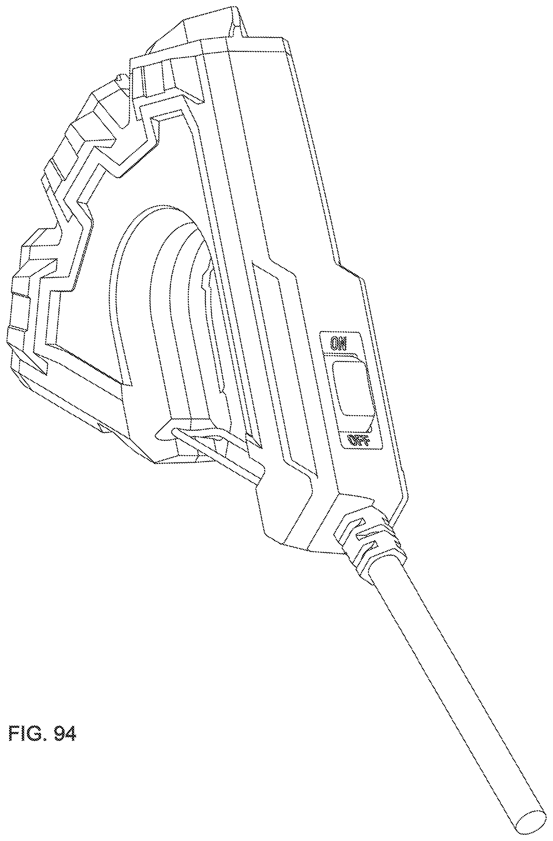
[0109] FIG. 94 is a perspective view of a third embodiment depicted with a gate and doors closed.
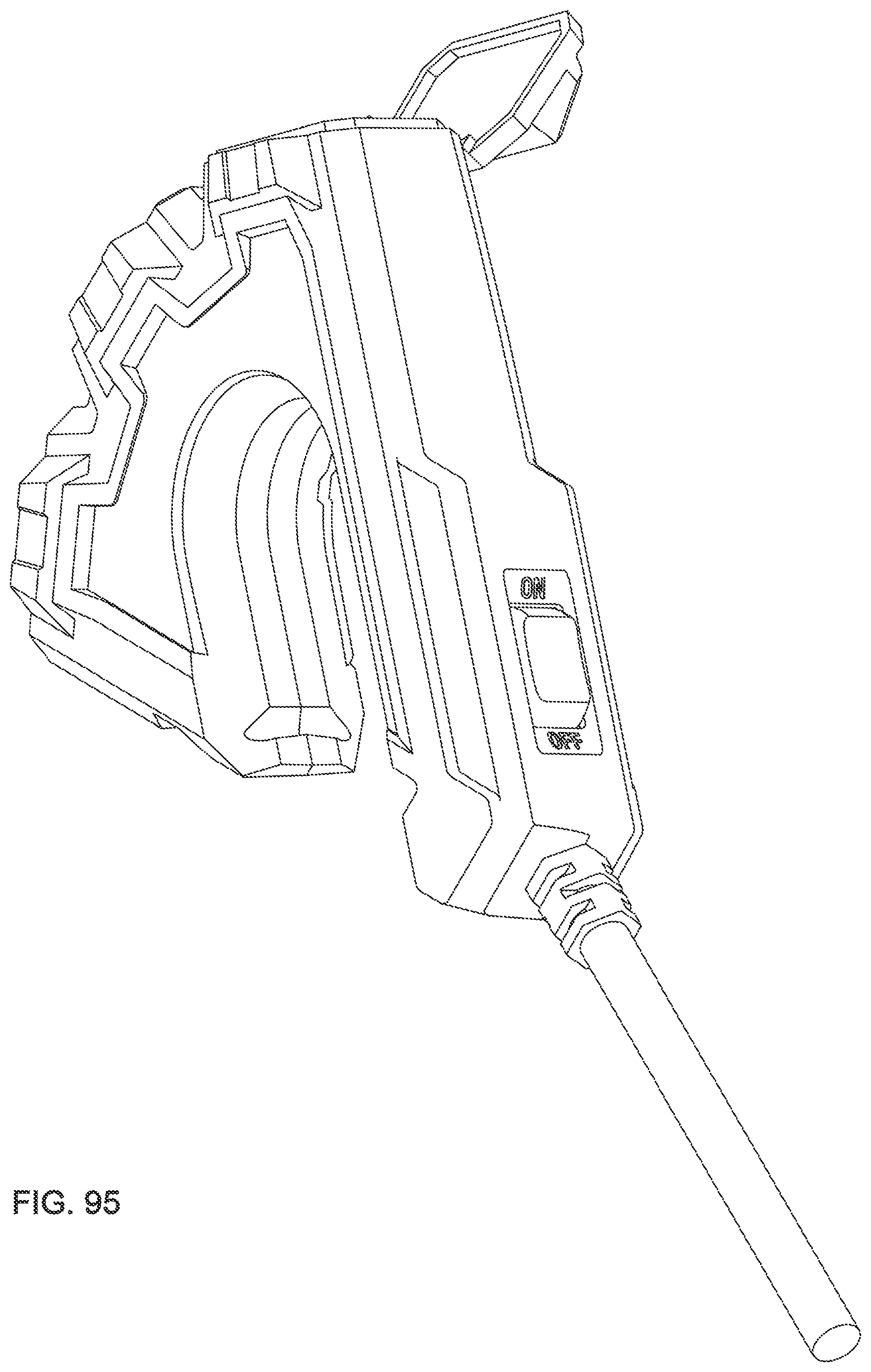
[0110] FIG. 95 is a perspective view of a third embodiment depicted with a gate and doors open.
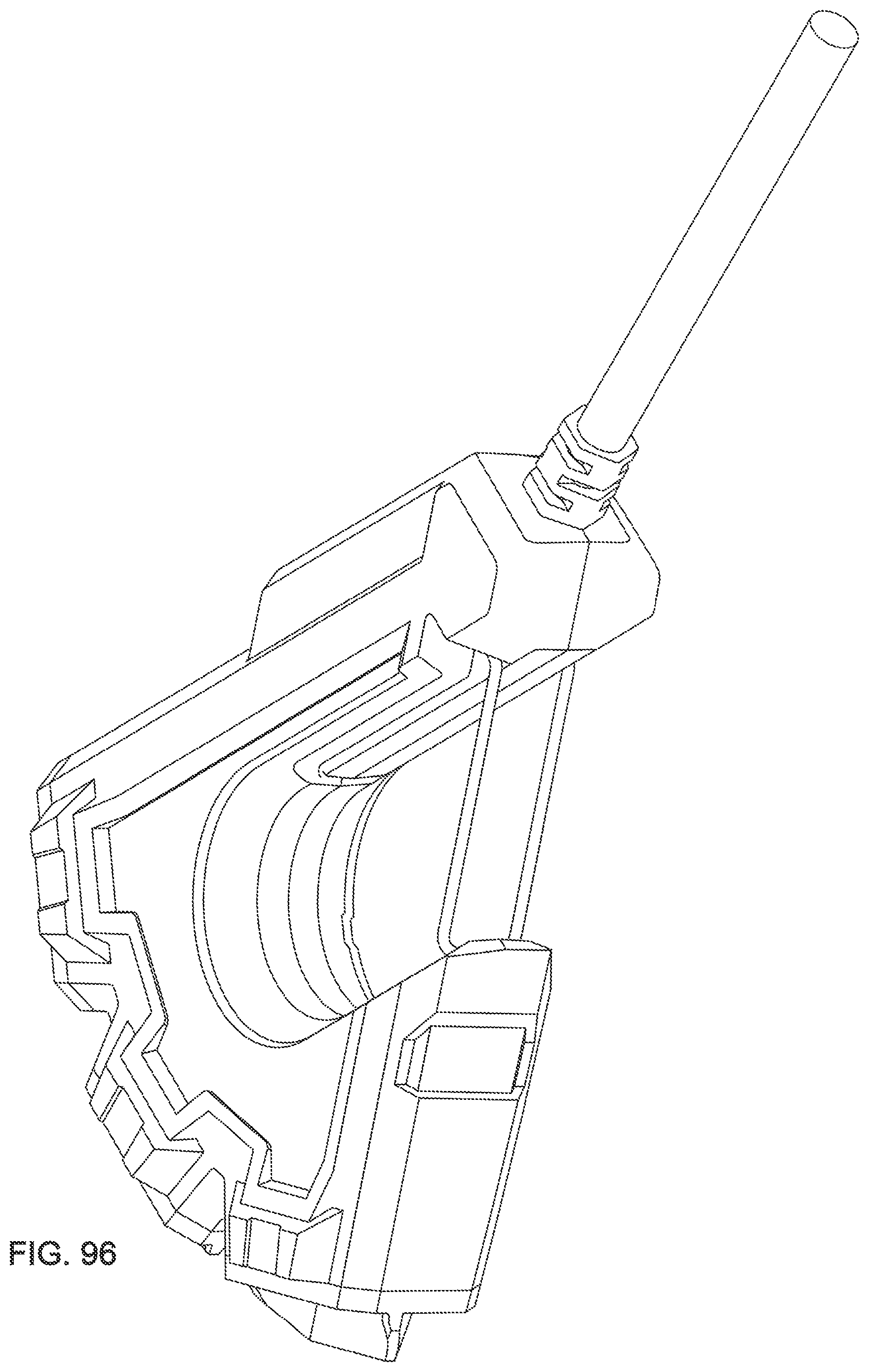
[0111] FIG. 96 is a perspective view of a third embodiment depicted with a gate and doors closed.
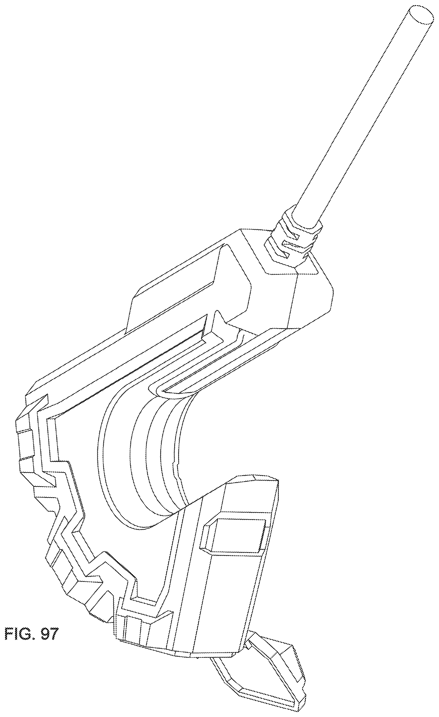
[0112] FIG. 97 is a perspective view of a third embodiment depicted with a gate and doors open.
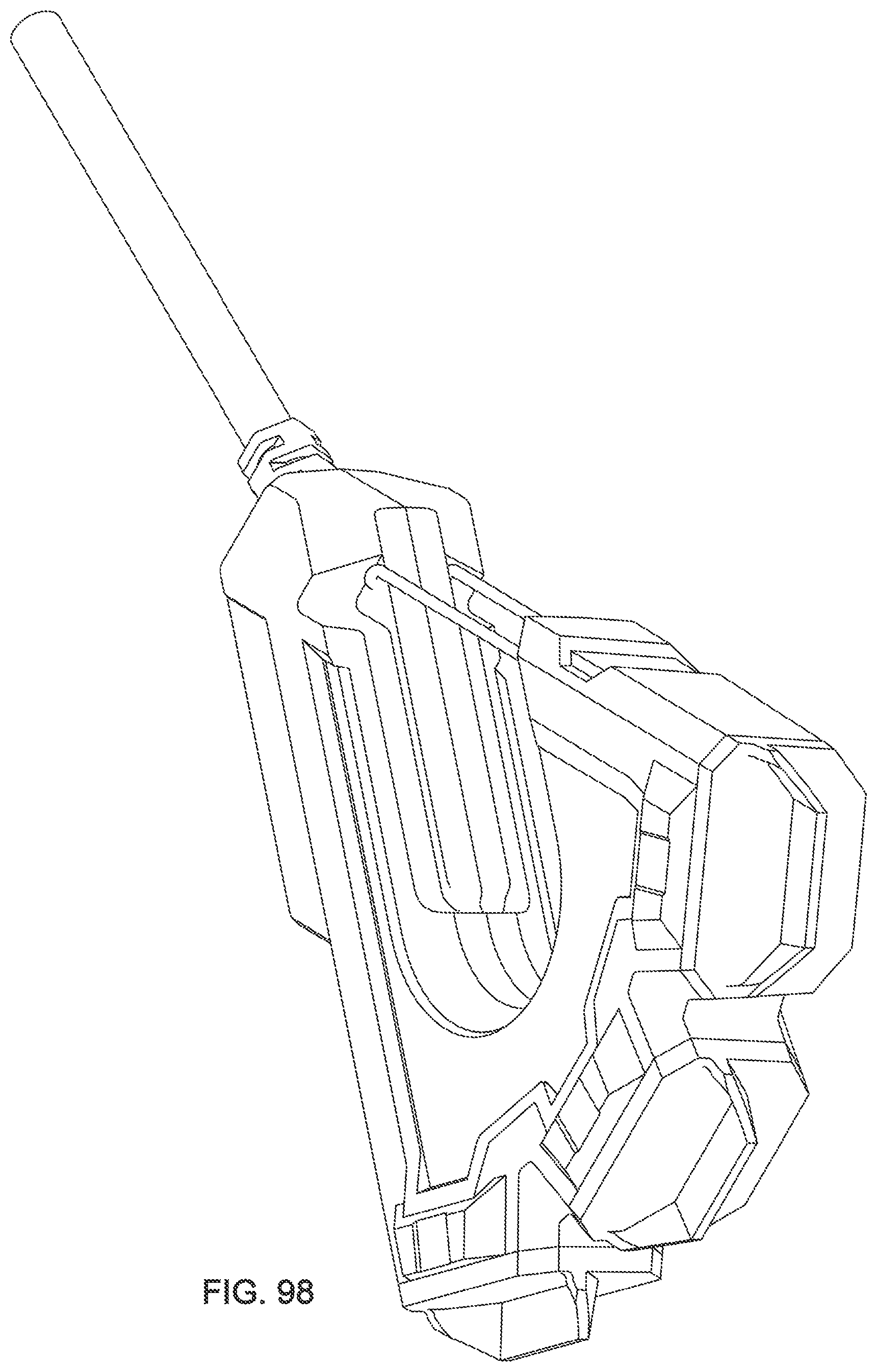
[0113] FIG. 98 is a perspective view of a third embodiment depicted with a gate and doors closed.
[0114] FIG. 99 is a perspective view of a third embodiment depicted with a gate and doors open.
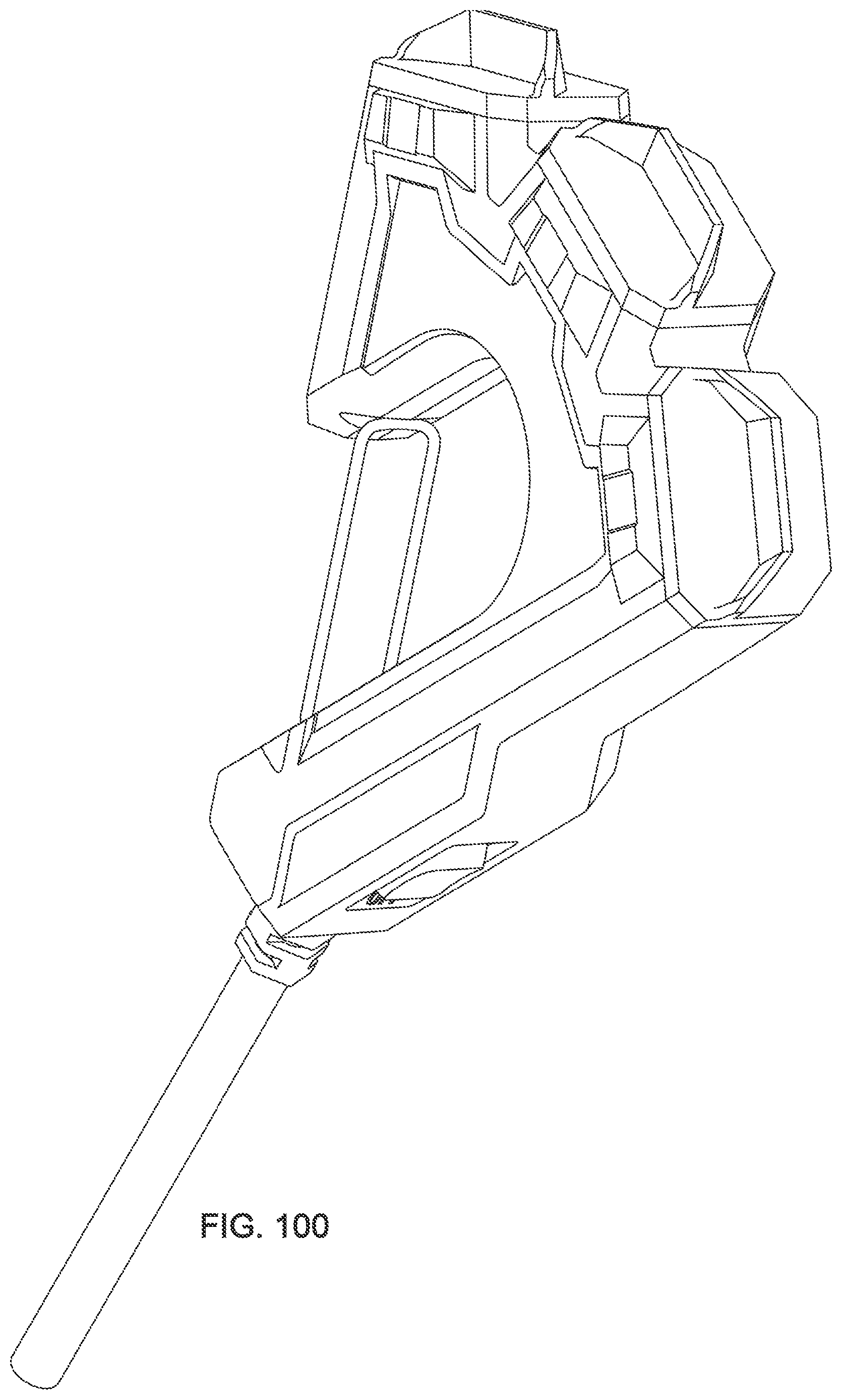
[0115] FIG. 100 is a perspective view of a third embodiment depicted with a gate and doors closed.
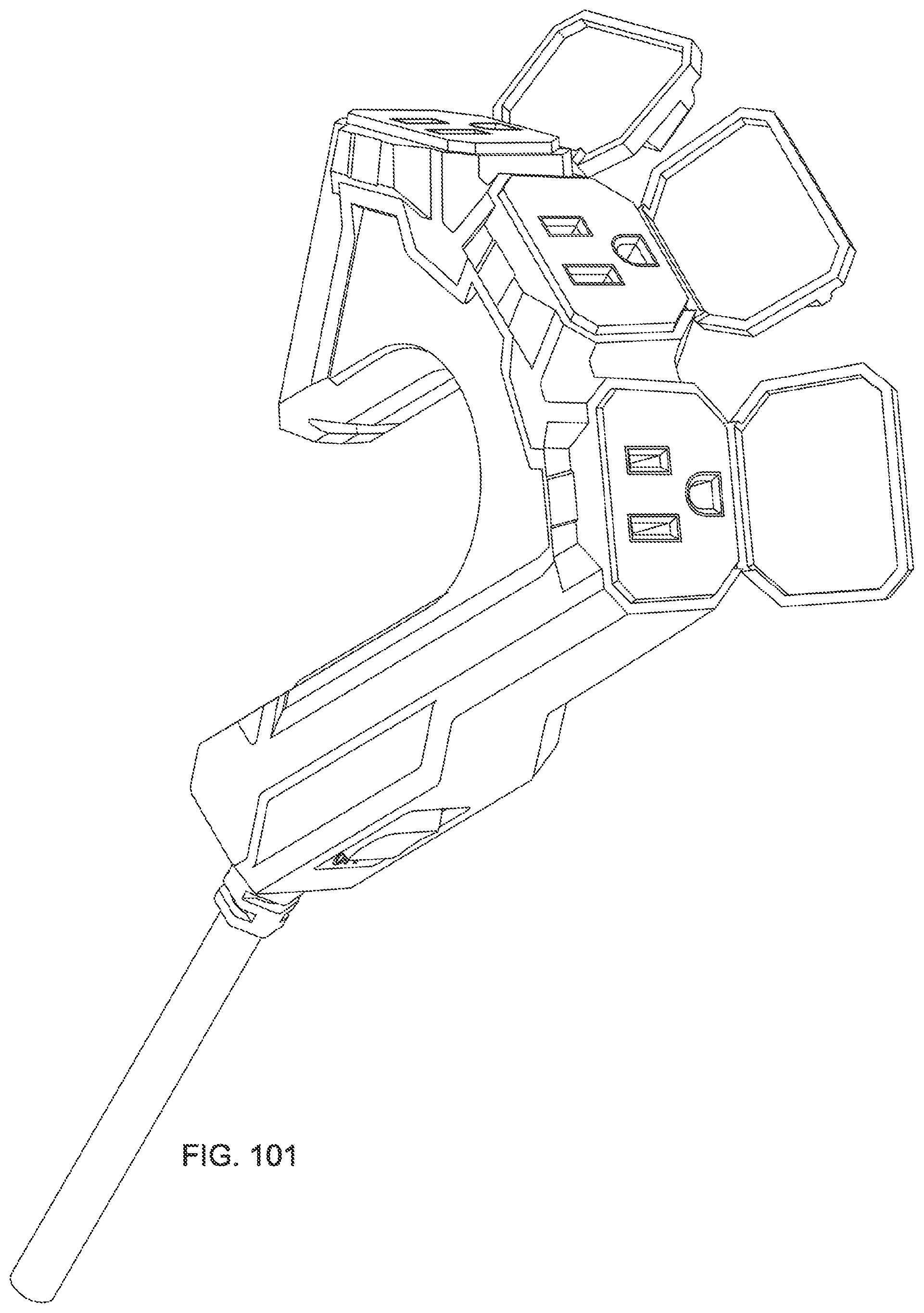
[0116] FIG. 101 is a perspective view of a third embodiment depicted with a gate and doors open.
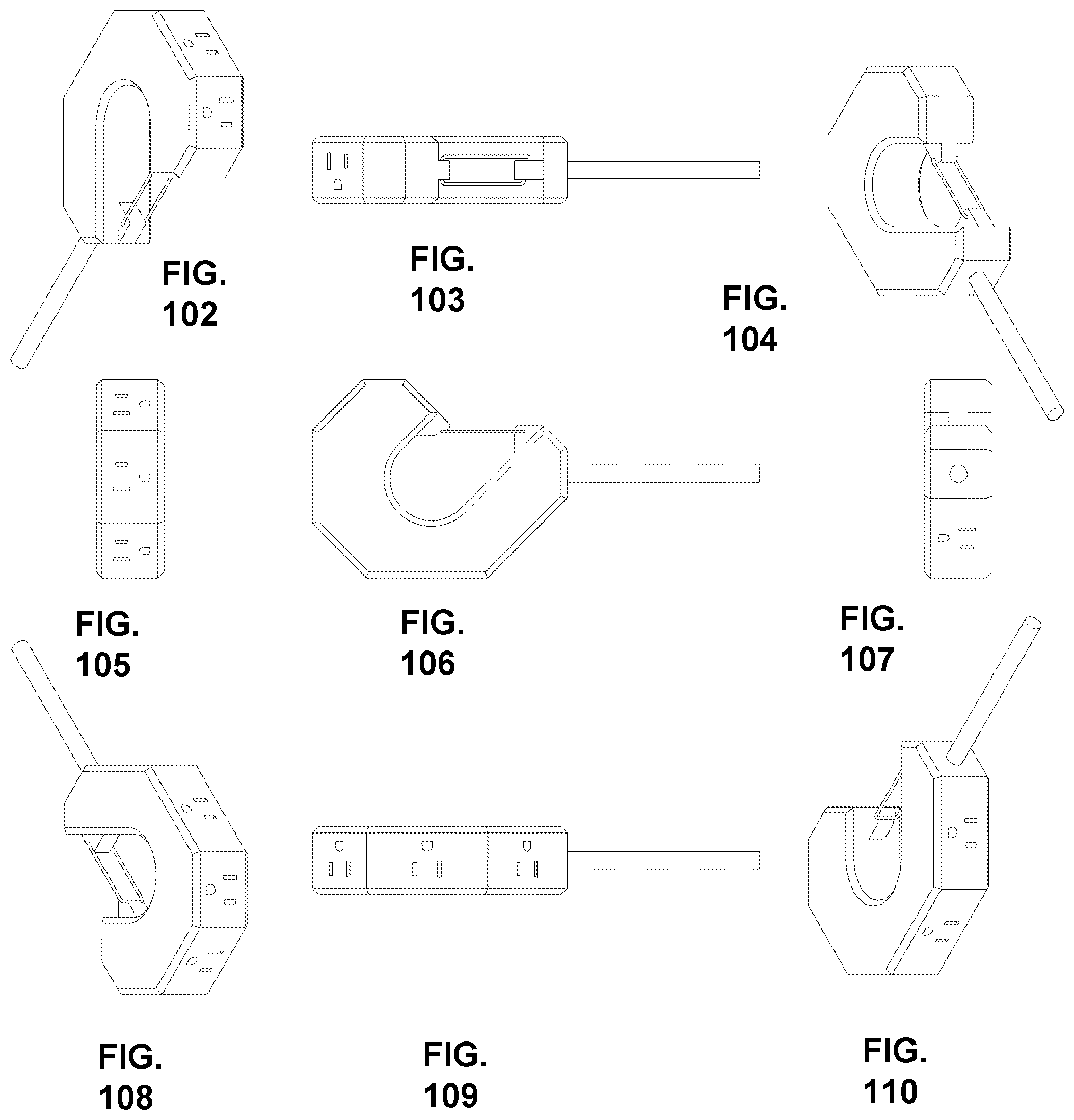
[0117] FIG. 102 is a perspective view of a forth embodiment.
[0118] FIG. 103 is a side view of a forth embodiment.
[0119] FIG. 104 is a perspective view of a forth embodiment.
[0120] FIG. 105 is a front view of a forth embodiment.
[0121] FIG. 106 is a top view of a forth embodiment.
[0122] FIG. 107 is a back view of a forth embodiment.
[0123] FIG. 108 is a perspective view of a forth embodiment.
[0124] FIG. 109 is a side view of a forth embodiment.
[0125] FIG. 110 is a perspective view of a forth embodiment.
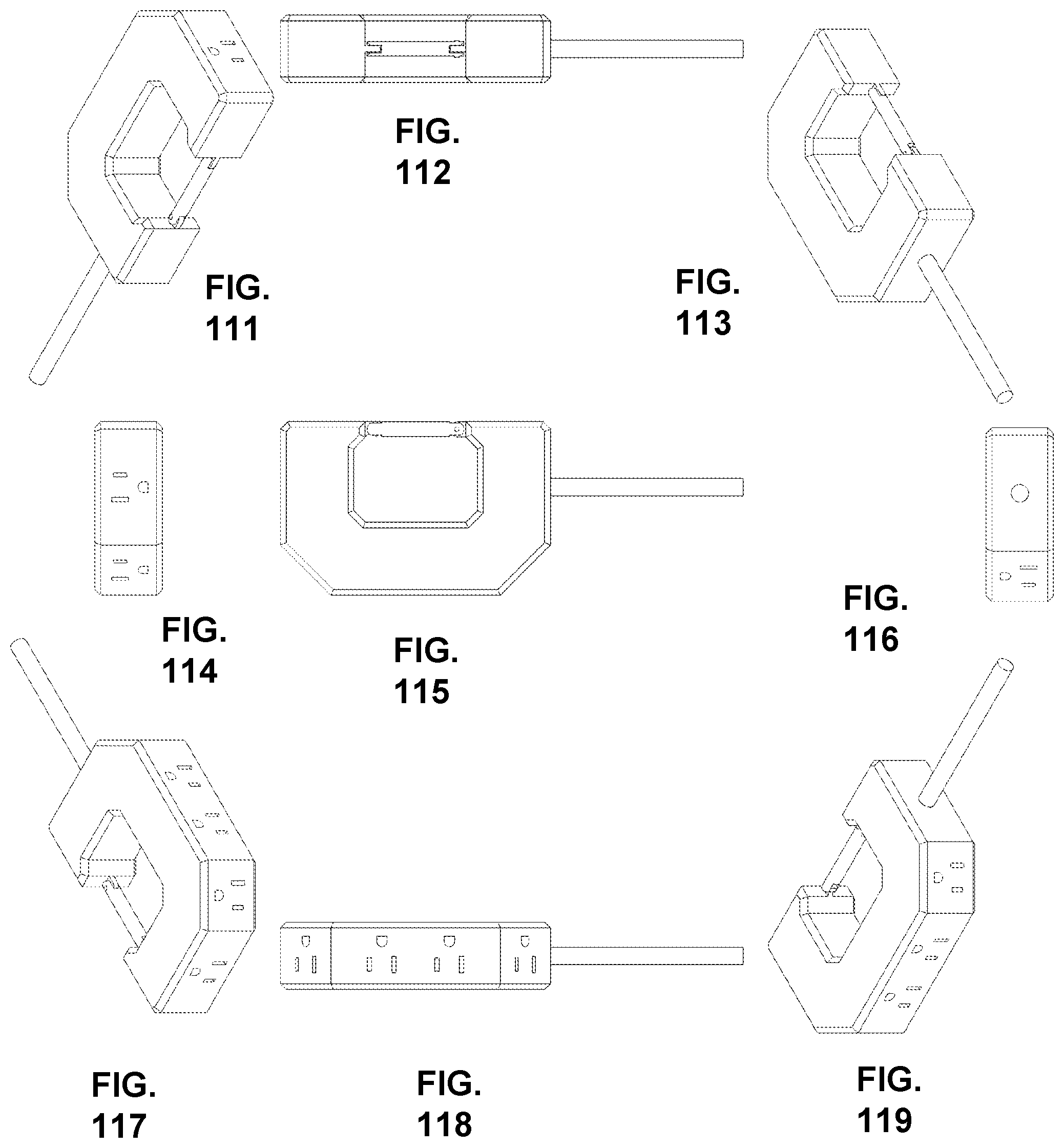
[0126] FIG. 111 is a perspective view of a fifth embodiment.
[0127] FIG. 112 is a side view of a fifth embodiment.
[0128] FIG. 113 is a perspective view of a fifth embodiment.
[0129] FIG. 114 is a front view of a fifth embodiment.
[0130] FIG. 115 is a top view of a fifth embodiment.
[0131] FIG. 116 is a back view of a fifth embodiment.
[0132] FIG. 117 is a perspective view of a fifth embodiment.
[0133] FIG. 118 is a side view of a fifth embodiment.
[0134] FIG. 119 is a perspective view of a fifth embodiment.
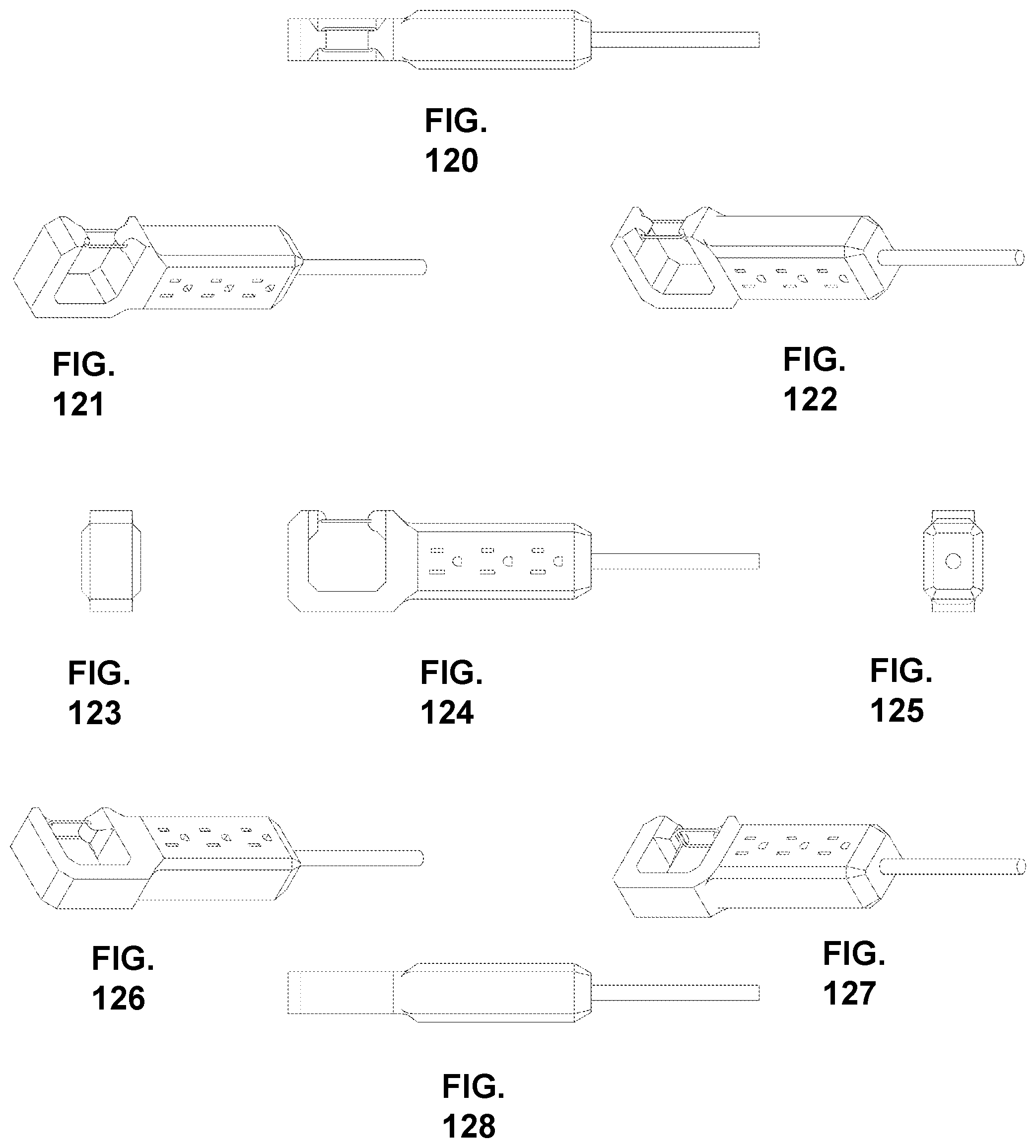
[0135] FIG. 120 is a side view of a sixth embodiment.
[0136] FIG. 121 is a perspective view of a sixth embodiment.
[0137] FIG. 122 is a perspective view of a sixth embodiment.
[0138] FIG. 123 is a front view of a sixth embodiment.
[0139] FIG. 124 is a top view of a sixth embodiment.
[0140] FIG. 125 is a back view of a sixth embodiment.
[0141] FIG. 126 is a perspective view of a sixth embodiment.
[0142] FIG. 127 is a perspective view of a sixth embodiment.
[0143] FIG. 128 is a side view of a sixth embodiment.
DESCRIPTION OF VARIOUS EMBODIMENTS
[0144] As used in this disclosure, the term "power plug" refers to a part of a power extension cord that is connected to an electrical supply, the term "receptacle head" refers to a part of a power extension cord that comprises one or more receptacles configured to supply electrical power received through a power plug, and the term "cord" refers to the assembly of electrical conductors connecting a power plug to a receptacle head. Unless otherwise defined, all terms (including technical and scientific terms) used herein have the same meaning as commonly understood by one having ordinary skill in the art to which this disclosure belongs. It will be further understood that terms, such as those defined in commonly used dictionaries, should be interpreted as having a meaning that is consistent with their meaning in the context of the relevant art and the present disclosure and will not be interpreted in an idealized or overly formal sense unless expressly so defined herein. References herein to orientations, surfaces, or other directions or structures as "upper," "top," "lower," "bottom," or having a "height," "width," or "length," and directional references such as "horizontal" and "vertical," are generally arbitrary and for convenience only with respect to the drawings, and those of skill in the art will recognize after appreciating this disclosure that such designations appropriately may be reoriented in particular embodiments. The terminology used herein is for the purpose of describing particular embodiments only and is not intended to be limiting. As used herein, the term "and/or" includes any and all combinations of one or more of the associated listed items. As used herein, the singular forms "a," "an," and "the" are intended to include the plural forms as well as the singular forms, unless the context clearly indicates otherwise. It will be further understood that the terms "comprises" and/or "comprising," when used in this specification, specify the presence of stated features, steps, operations, elements, and/or components, but do not preclude the presence or addition of one or more other features, steps, operations, elements, components, and/or groups thereof.
[0145] In describing various embodiments, it will be understood that a number of structures and steps are disclosed. Each of these has individual benefits and each can also be used in conjunction with one or more, or in some cases all, of the other disclosed structures and steps. Accordingly, for the sake of clarity, this description will refrain from repeating every possible combination of the individual structures and steps in an unnecessary fashion. Nevertheless, the specification and claims should be read with the understanding that such combinations are entirely within the scope of the disclosure and the claims. Those of skill in the art will recognize after appreciating this disclosure that the steps of the various methods, processes, and other techniques disclosed herein need not be performed in any particular order, unless otherwise expressly stated or logically necessary to satisfy expressly stated conditions.
[0146] The present disclosure is to be considered as an exemplification of various embodiments, and is not intended to limit the scope of the claims or the disclosure to the specific embodiments illustrated by the figures or description below. After appreciating this disclosure those skilled in the art will recognize that the invention may be embodied in a variety of different forms and that various changes, substitutions, and alterations can be made without departing from the spirit and scope of the invention. FIGS. 1-5 and 8-11 illustrate a currently preferred embodiment.
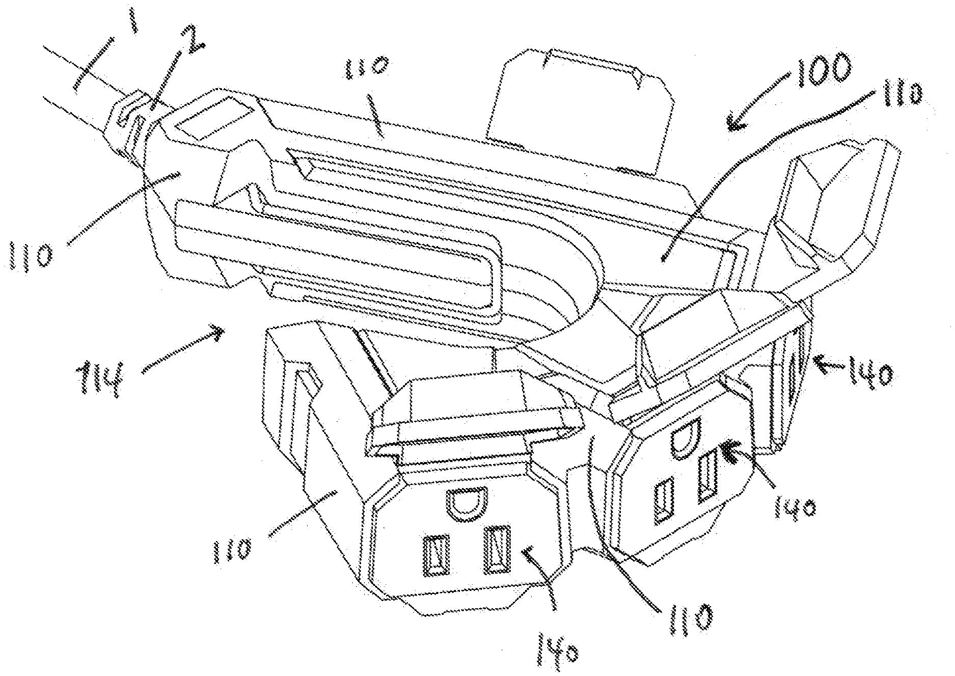
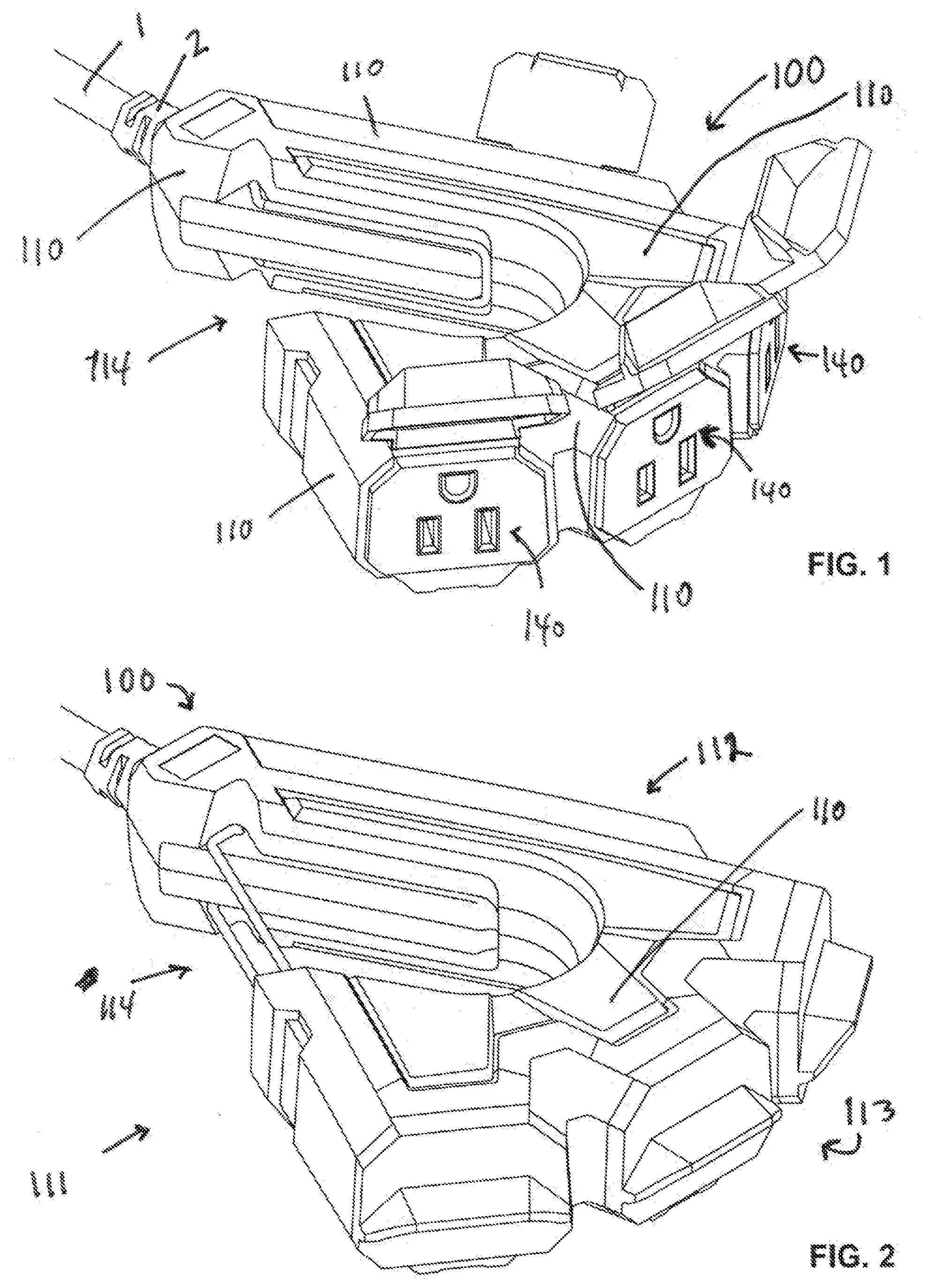
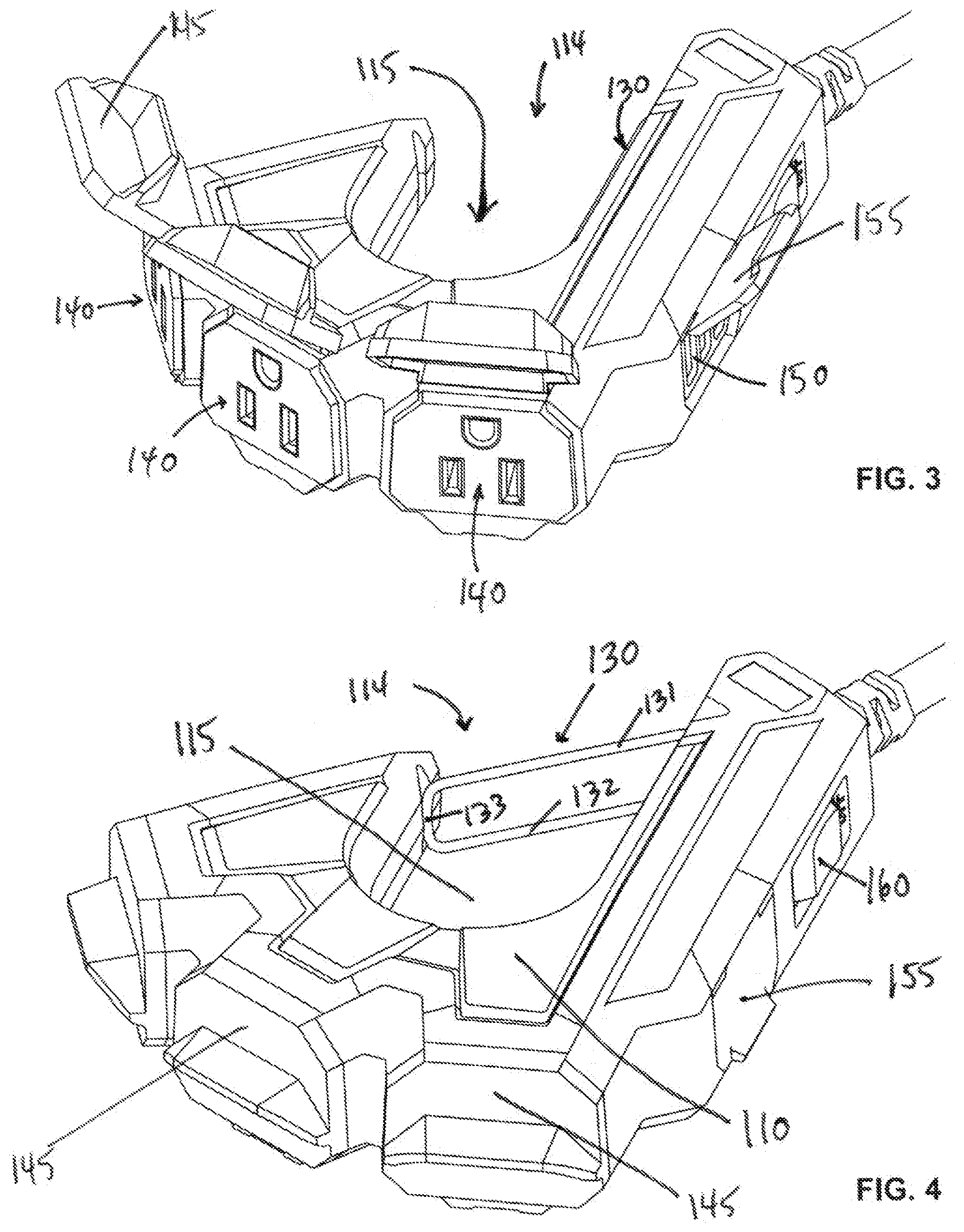
[0147] FIGS. 1-5 and 8-11 depict a first embodiment of a receptacle head. In this embodiment, receptacle head 100 comprises body 110 having a generally triangular shape, with power cord 1 attached to a vertex of generally triangularly shaped body 110 by strain relief 2. Body 110 comprises a "cavity" or "hole," identified in the drawings by reference 115, which extends completely through body 110. First side 111 of generally triangularly shaped body 110 comprises gap 114 that extends through to cavity 115, such that cavity 115 is accessible from the exterior of the receptacle head through gap 114 along first side 111 when gap 114 is unobstructed. Configuring the receptacle head with a cavity accessible from the exterior of the receptacle head through a gap in the receptacle head enables the power extension cord when in use to be hung on, held, or supported by a supporting structure, for example a ladder rung, a scaffold bar or strut, a stationary tool handle, a workpiece, a rod, a wire, a pipe, a doorknob, or any similar type structure that will fit within the cavity.
[0148] As shown in FIGS. 1-5 and 8-11, this embodiment comprises gate 130. As shown in FIGS. 3, 10, 11, and others, gate 130 is configured to have an open position in which access to cavity 115 is available through an unobstructed gap 114. As shown in FIGS. 4, 8, 9, and others, gate 130 is further configured to have a closed position in which access to cavity 115 through gap 114 is obstructed by gate 130. In this embodiment, gate 130 is configured as a skeletonized tongue formed with small round bar stock or large gauge wire, and comprises upper arm 131 and lower arm 132, which are connected by catch 133 extending between upper arm 131 and lower arm 132. In other embodiments, however, other gate configurations may be deployed. For example, the embodiment depicted in FIGS. 18-23 deploys a tubular gate 330 articulating about a hinge pin 339 attached to body 310, which further deploys a hook-type striker 317 configured to engage a recessed catch disposed on the opposite end of gate 330 from hinge pin 339. Other embodiments may deploy other configurations of gates, for example, a planar tongue.
[0149] Gate 130 in the embodiment shown in FIGS. 1-5 and 8-11 attaches to body 110 via upper hinge 136 and lower hinge 138. In the closed position, gate 130 extends completely across gap 114 from the attachment of one end of gate 130 to body 110 at upper hinge 136 and lower hinge 136, to the engagement at the other end of gate 130 of catch 133 with striker 117. In the depicted embodiment, the lip of striker 117 is sufficiently elastic to compress for passage of catch 133 and resile when gate 130 is fully closed to provide a restraining force against catch 133 biasing gate 130 in the closed position. In the fully open position, gate 130 clears gap 114 and is substantially disposed in the recess 118 formed in an interior wall of cavity 115. In some embodiments, recess 118 may be formed with a lip sufficiently elastic to compress for passage of catch 133 and resile when gate 130 is fully open to provide a restraining force against catch 133 biasing gate 130 in the open position. Although configuring a receptacle head with a gate is preferred to enhance retention of the receptacle head to a supporting structure disposed in the cavity, other embodiments may be deployed omitting a gate. In embodiments which deploy a gate, configuration of the receptacle head with a gate recess and a gate striker are preferred to enhance retention of the gate in the open and closed positions, but are optional, and may be omitted, individually or in combination, in other embodiments.
[0150] In the embodiment depicted in FIGS. 1-5 and 8-11, upper hinge 136 extends angularly from upper arm 131 a first length before turning downward and entering a recess in the upper surface of body 110. Lower hinge 138 extends angularly from lower arm 132 a second distance before turning upward and entering a recess in the lower surface of body 110. In this embodiment, the first length of upper hinge 136 is greater than the second length of lower hinge 138, but other embodiments may reverse this configuration or configure the hinges with equal length. By configuring the hinges with unequal lengths for example as shown in FIGS. 1-5 and 8-11, however, gate 130 may be provided with a first force tending to bias gate 130 in the closed position when catch 133 is proximal to gate striker 117 and a second force tending to bias gate 130 in the open position when catch 133 is proximal to the recess 118. Other means of biasing gate 130 may be used, for example a coil, leaf, or other discrete type of spring, or the use of elastomeric material, for example by deployment of an elastomeric gate fixedly attached to the body. Although upper hinge 136 extends angularly from upper arm 131 and lower hinge 138 extends angularly from lower arm 132 in the preferred embodiment, angular extension is optional and may be admitted, for example in the embodiments depicted in FIGS. 12-17 and FIGS. 24-29, in which biasing forces are provided by the unequal lengths of upper arm 231 with respect to lower arm 232, and upper arm 431 with respect to lower arm 432, respectively.
[0151] The embodiment of FIGS. 1-5 and 8-11 deploys a USB receptacle array 150 along the outside perimeter of a second side 112 of generally triangularly shaped body 110. USB receptacle array 150 in this embodiment comprises three USB type A receptacles, but other embodiments may deploy only one, only two, or more than three receptacles. In yet other embodiments, other types of USB receptacles may be deployed, or multiple types of USB receptacles may be deployed, for example an array comprising a USB type A receptacle, a USB mini type A receptacle, and a USB micro type AB receptacle. Other embodiments may deploy one or more other non-NEMA types of receptacles, for example cigar lighter receptacles, EIAJ power receptacles, or IEC 60130-10 power receptacle, in any numbers or combinations. Yet other embodiments may combine one or more USB receptacles with one or more non-NEMA receptacles. In the preferred embodiment depicted in FIGS. 1-5 and 8-11, USB receptacle array 150 is deployed along the outside profile of body 110, where the "profile" of body 110 is understood to be the perimeter outline of body 110 when viewing directly through cavity 115, but other embodiments may deploy non-NEMA types of receptacles in other locations on the surface of body 110, for example the upper or lower surface or both.
[0152] In the embodiment of FIGS. 1-5 and 8-11, the outside perimeter of a third side 113 of generally triangularly shaped body 110 is trifurcated to deploy three NEMA 5-15R AC power receptacles 140. Other embodiments may deploy only one, only two, or more than three AC power receptacles. In yet other embodiments, other types of NEMA AC power receptacles may be deployed, for example NEMA 5-20R AC power receptacles, NEMA L5-30R AC power receptacles, or NEMA 6-30R AC power receptacles, in any numbers or combinations. In other embodiments in which the power plug and the power cord are properly configured, the receptacle head may be configured to comprise one or more 120 volt AC receptacles in combination with one or more 240 volt AC receptacles. In the embodiment of FIGS. 1-5 and 8-11, the furcations of the third side 113 are arranged arcuately, so that the faces of receptacles 140 are not coplanar, but other embodiments may range one or more AC receptacles along a strait side with or without furcations, and with or without the faces of receptacles 140 being coplanar. In the preferred embodiment depicted in FIGS. 1-5 and 8-11, AC receptacles 140 are deployed along the outside profile of body 110 (i.e., along the outside of side 113), but other embodiments may deploy AC receptacles in other locations, for example along a surface that is not along a profile perimeter of the body, for example as depicted in FIGS. 24-29.
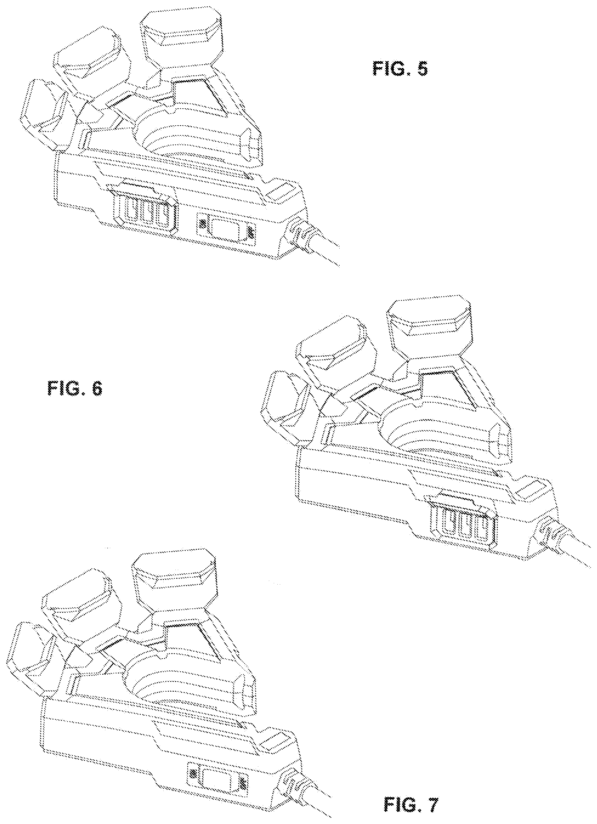
[0153] Various embodiments such as that depicted in FIGS. 1-5 and 8-11 may comprise a master switch, such as switch 160, to activate one or more receptacles. In the embodiment depicted in FIGS. 1-5 and 8-11, in an off position switch 160 deactivates all AC receptacles 140 and all USB receptacles in USB receptacle array 150, and when switch 160 is in the on position all receptacles are live. In other embodiments, a switch may be configured to activate and deactivate only selected receptacles. In yet other embodiments, multiple switches may be deployed and configured to activate and deactivate various combinations of receptacles. Other embodiments may also deploy one or more switches comprising integral breaker elements to deactivate all or selected receptacles upon a power surge occurrence or voltage spike, or alternatively deploy one or more individual breaker elements.
[0154] The embodiment depicted in FIGS. 1-5 and 8-11 further comprises receptacle covers. As shown, AC receptacle doors 145 are hinged adjacent to respective AC receptacles 140, and maybe articulated upward for access to the receptacles or downward to cover the receptacles. Similarly, USB receptacle door 155 is hinged adjacent to USB receptacle array 150, and maybe articulated upward for access to the receptacles or downward to cover the receptacles. In the preferred embodiment, when closed doors 145 and door 155 seal tightly with body 110, preferably rendering receptacle head 100 weatherproof, but at least weather resistant. To enhance weatherproofing or weather resistance, switch 160 may be configured or augmented with a membrane cover rendering switch 160 weatherproof or at least weather resistant.
[0155] Various embodiments may be configured with different auxiliary features, i.e., structures other than a power cord, a strain relief, a gate, or receptacles. For example, FIG. 6 depicts an embodiment similar to that of FIGS. 1-5 and 8-11 but without a power switch. For further example, FIG. 7 depict an embodiment similar to that of FIGS. 1-5 and 8-11 but without USB receptacles. Yet other embodiments may comprise additional or different auxiliary features, for example a work light, a clock, an LP detector, or a small media player, or any combination thereof. Unless constrained by the position of other features, any auxiliary feature may be disposed anywhere on the body.
[0156] Although body 110 comprises a generally triangular shape, other embodiments may be deployed with bodies having yet other shapes, provided that the shape allows configuration of the body with a cavity (such as cavity 115) extending completely through the body and a gap (such as gap 114) disposed along a perimeter of the body that extends through to the cavity, with the cavity being accessible from the exterior of the receptacle head through the gap. For example the receptacle head 200 depicted in FIGS. 12-17 comprises body 210 having a "question mark" shaped profile. Body 210 comprises cavity 215 extending completely through body 210 and gap 214 disposed along the "question mark" shaped perimeter of body 210 that extends through to cavity 215. This embodiment further comprises gate 230 comprising upper arm 231, lower arm 232, catch 233, upper hinge 236, and lower hinge 238. In this embodiment, the length of upper arm 231 from hinge 236 to catch 233 is less than the length of lower arm 232 from hinge 238 to catch 233, with this configuration tending to exert a force biasing gate 233 in the closed position, with catch 233 engaged with striker 217. Similarly to striker 117 described above, striker 217 may be resilient and operate as a restraint holding gate 230 in the closed position. This embodiment comprises AC receptacles 240 disposed around the perimeter of the "question mark" shaped profile of body 210, but in other embodiments one or more AC receptacles may be deployed along upper surface 211 of body 210 or lower surface 212 of body 210, or both.
[0157] FIGS. 18-23 depict another embodiment not having a body with a generally triangular shape. As shown, receptacle head 300 comprises body 310 having a "C" or "U" shaped profile. Body 310 comprises cavity 315 extending completely through body 310 and gap 314 disposed along the "C" or "U" shaped perimeter of body 310 that extends through to cavity 315. This embodiment further comprises gate 330 comprising catch 333 and hinge pin 339. Gate 330 articulates around hinge pin 339 from an open position in which gap 314 is clear that provides access to cavity 315, to a closed position in which gap 314 is blocked by gate 330, with gate catch 333 of gate 330 engaging striker 317 disposed on body 310. In this embodiment, striker 317 comprises a hook shape configured to engage a recessed in catch 333, with the engagement of the hook shape in the recess mitigating any elongation of gap 314 caused by forces exerted along either or both arms of body 310. A coil spring, not depicted, is housed in a cavity of gate 330 and attached to body 310 proximal to hinge pin 339 and to gate 330 proximal to catch 333, with a coil spring exerting a force biasing gate 330 in the closed position. This embodiment comprises AC receptacles 340 disposed around the perimeter of the "C" or "U" shaped profile of body 310, but in other embodiments one or more AC receptacles may be deployed along upper surface 311 of body 310 or lower surface 312 of body 310, or both.
[0158] FIGS. 24-29 depict another embodiment not having a body with a generally triangular shape. As shown, receptacle head 400 comprises body 410 having a generally rectangularly shaped profile. Body 410 comprises cavity 415 extending completely through body 410 and gap 414 disposed along the generally rectangularly shaped perimeter of body 410 that extends through to cavity 415. This embodiment further comprises gate 430 comprising upper arm 431, lower arm 432, catch 433, upper hinge 436, and lower hinge 438. In this embodiment, the length of upper arm 431 from hinge 436 to catch 433 is less than the length of lower arm 432 from hinge 438 catch 433, with this configuration tending to exert a force biasing gate 433 in the closed position, with catch 433 engaged with striker 417. Similarly to striker 117 described above, striker 417 may be resilient and operate as a restraint holding gate 430 in the closed position. This embodiment comprises AC receptacles 440 disposed around the perimeter of the generally rectangularly shaped profile of body 410, but in other embodiments one or more AC receptacles may be deployed along upper surface 411 of body 410 or lower surface 412 of body 410, or both.
[0159] In the preferred embodiment, body 110 is formed by injection molding thermoplastic elastomers, thermoplastic rubbers, or liquid silicone rubber around the electrical components of the receptacles, the auxiliary features, and the interconnecting wiring. Other embodiments of the body also may be injection molded with those or similar compounds. Alternatively, yet other embodiments may have the body formed as a rigid or elastic shell housing, for example an upper shell housing and a lower shell housing, with the body assembled by placing the shell components around the electrical components of the receptacles, the auxiliary features, and the interconnecting wiring and securing the shell components in place to form a unitary housing, for example with fasteners, adhesives, or ultrasonic or thermal welding. Shells and shell components may be formed of many types of rigid or elastic materials, for example metals, plastic polymers, or other materials, provided the materials are suitable for forming a unitary body configured to house the electrical components of the receptacles, the auxiliary features, and the interconnecting wiring and provide access to the device connection structures of the receptacles and the operating controls of the auxiliary features.
[0160] The described embodiments are illustrative only and are not restrictive, and the scope of the invention is defined solely by the following claims.
* * * * *
D00000
D00001
D00002
D00003
D00004
D00005
D00006
D00007
D00008
D00009
D00010
D00011
D00012
D00013
D00014
D00015
D00016
D00017
D00018
D00019
D00020
D00021
D00022
D00023
D00024
D00025
D00026
D00027
D00028
D00029
D00030
D00031
D00032

D00033
D00034
D00035
D00036
D00037
D00038
D00039
D00040
D00041
D00042
D00043

D00044
D00045
D00046

D00047
D00048
D00049
D00050
D00051
D00052
D00053
D00054
D00055
D00056
D00057
D00058
D00059
D00060
D00061
D00062
D00063
D00064
D00065

D00066
D00067
D00068
D00069
D00070
D00071
D00072
D00073
D00074
D00075
D00076
D00077
D00078

D00079
D00080
D00081
D00082
D00083
XML
uspto.report is an independent third-party trademark research tool that is not affiliated, endorsed, or sponsored by the United States Patent and Trademark Office (USPTO) or any other governmental organization. The information provided by uspto.report is based on publicly available data at the time of writing and is intended for informational purposes only.
While we strive to provide accurate and up-to-date information, we do not guarantee the accuracy, completeness, reliability, or suitability of the information displayed on this site. The use of this site is at your own risk. Any reliance you place on such information is therefore strictly at your own risk.
All official trademark data, including owner information, should be verified by visiting the official USPTO website at www.uspto.gov. This site is not intended to replace professional legal advice and should not be used as a substitute for consulting with a legal professional who is knowledgeable about trademark law.