Holster with Rotatable Ejection Port Locking Element
Yeates; Eric M.
U.S. patent application number 17/550536 was filed with the patent office on 2022-04-07 for holster with rotatable ejection port locking element. This patent application is currently assigned to Sentry Solutions Products Group LLC. The applicant listed for this patent is Sentry Solutions Products Group LLC. Invention is credited to Eric M. Yeates.
| Application Number | 20220107159 17/550536 |
| Document ID | / |
| Family ID | 1000006074842 |
| Filed Date | 2022-04-07 |


View All Diagrams
| United States Patent Application | 20220107159 |
| Kind Code | A1 |
| Yeates; Eric M. | April 7, 2022 |
Holster with Rotatable Ejection Port Locking Element
Abstract
A holster defining an at least partial holster cavity; and a release lever pivotably attached or coupled to the holster body and repeatably pivotable between a retention position and a release position, and wherein the release lever is capable of being pivoted to the release position when a pivoting force is applied to the release lever, wherein if the release lever is in the retention position, at least a portion of a handgun locking portion of the release lever is positioned so as to protrude into a portion of the holster cavity a sufficient distance to engage at least a portion of an ejection port of an inserted handgun, and wherein if the release lever in the release position, the handgun locking portion is withdrawn from the holster cavity to disengage from the ejection port of the handgun.
| Inventors: | Yeates; Eric M.; (Virginia Beach, VA) | ||||||||||
| Applicant: |
|
||||||||||
|---|---|---|---|---|---|---|---|---|---|---|---|
| Assignee: | Sentry Solutions Products Group
LLC Virginia Beach VA |
||||||||||
| Family ID: | 1000006074842 | ||||||||||
| Appl. No.: | 17/550536 | ||||||||||
| Filed: | December 14, 2021 |
Related U.S. Patent Documents
| Application Number | Filing Date | Patent Number | ||
|---|---|---|---|---|
| 16658740 | Oct 21, 2019 | 11199377 | ||
| 17550536 | ||||
| 15683566 | Aug 22, 2017 | 10451382 | ||
| 16658740 | ||||
| 62378648 | Aug 23, 2016 | |||
| Current U.S. Class: | 1/1 |
| Current CPC Class: | F41C 33/041 20130101; F41C 33/0227 20130101 |
| International Class: | F41C 33/02 20060101 F41C033/02; F41C 33/04 20060101 F41C033/04 |
Claims
1. A holster for a handgun, comprising: a holster body defining an at least partial holster cavity; a hood pivotably attached or coupled to said holster body, wherein said hood is repeatably pivotable between a closed position and an open position, wherein said hood is biased to said open position via interaction between a holster/hood biasing element attached or coupled between a portion of said holster body and a portion of said hood; and a release lever pivotably attached or coupled to said holster body, wherein said release lever is repeatably pivotable between a retention position and a release position, wherein said release lever is biased to said retention position via interaction between a holster/lever biasing element attached or coupled to a portion of said holster body, and wherein said release lever is capable of being pivoted to said release position when a pivoting force is applied to said release lever, wherein if said release lever is in said retention position, at least a portion of a handgun locking portion of said release lever is positioned so as to extend through an aperture in a wall portion of said holster body, and protrude into a portion of said holster cavity a sufficient distance to engage at least a portion of an ejection port of an inserted handgun, and wherein if said release lever in said release position, said handgun locking portion is withdrawn from said holster cavity a sufficient distance to disengage from said ejection port of said handgun to allow said handgun to be withdrawn from said holster cavity, wherein if said hood is in said closed position and said release lever is in said retention position, a tab of said holster/lever biasing element protrudes into at least a portion of a hood locking recess of said hood, thereby maintaining said hood in said closed position, and wherein if said bias of said release lever is overcome and said release lever is pivoted from said retention position to said release position, said tab disengages from said hood locking recess and said hood is allowed to pivot to said open position.
2. The holster of claim 1, wherein if said hood is in said open position, said hood does not hinder said handgun from being withdrawn from said holster.
3. The holster of claim 1, wherein said at least partial holster cavity includes a holster frame top portion and a holster frame bottom portion.
4. The holster of claim 1, wherein said at least partial holster cavity includes a holster slide portion and a holster trigger guard portion.
5. The holster of claim 1, wherein said holster includes at least one holster frame attachment portion, which provides one or more areas, portions, or devices for fastening said holster to a belt loop or other holster holding device.
6. The holster of claim 1, wherein said hood comprises a hood pivot stop, which corresponds to a hood stop surface formed in a surface portion of said holster body such that said hood pivot stop and said hood stop surface are aligned such that if said hood pivots towards said open position, said hood pivot stop contacts said hood stop surface to stop further rotation of said hood relative to said holster body.
7. The holster of claim 1, wherein said release lever is pivotally connected to said holster body, via said release lever pivot pin, so that said release lever is repeatably pivotable between said retention position and said release position.
8. The holster of claim 1, wherein a release lever pivot pin may extend either all or part of said way across a release lever extension portion, joining said thumb/finger engagement portion and said locking engagement portion.
9. The holster of claim 1, wherein said handgun locking portion includes a substantially planar portion having a substantially planar surface formed so as to extend into at least a portion of said ejection port of an inserted handgun and engage a surface of said ejection port.
10. A holster for a handgun, comprising: a holster body defining an at least partial holster cavity; and a release lever pivotably attached or coupled to said holster body, wherein said release lever is repeatably pivotable between a retention position and a release position, wherein said release lever is biased to said retention position via interaction between a holster/lever biasing element attached or coupled to a portion of said holster body, and wherein said release lever is capable of being pivoted to said release position when a pivoting force is applied to said release lever, wherein if said release lever is in said retention position, at least a portion of a handgun locking portion of said release lever is positioned so as to extend through an aperture in a wall portion of said holster body, and protrude into a portion of said holster cavity a sufficient distance to engage at least a portion of an ejection port of an inserted handgun, and wherein if said release lever in said release position, said handgun locking portion is withdrawn from said holster cavity a sufficient distance to disengage from said ejection port of said handgun to allow said handgun to be withdrawn from said holster cavity.
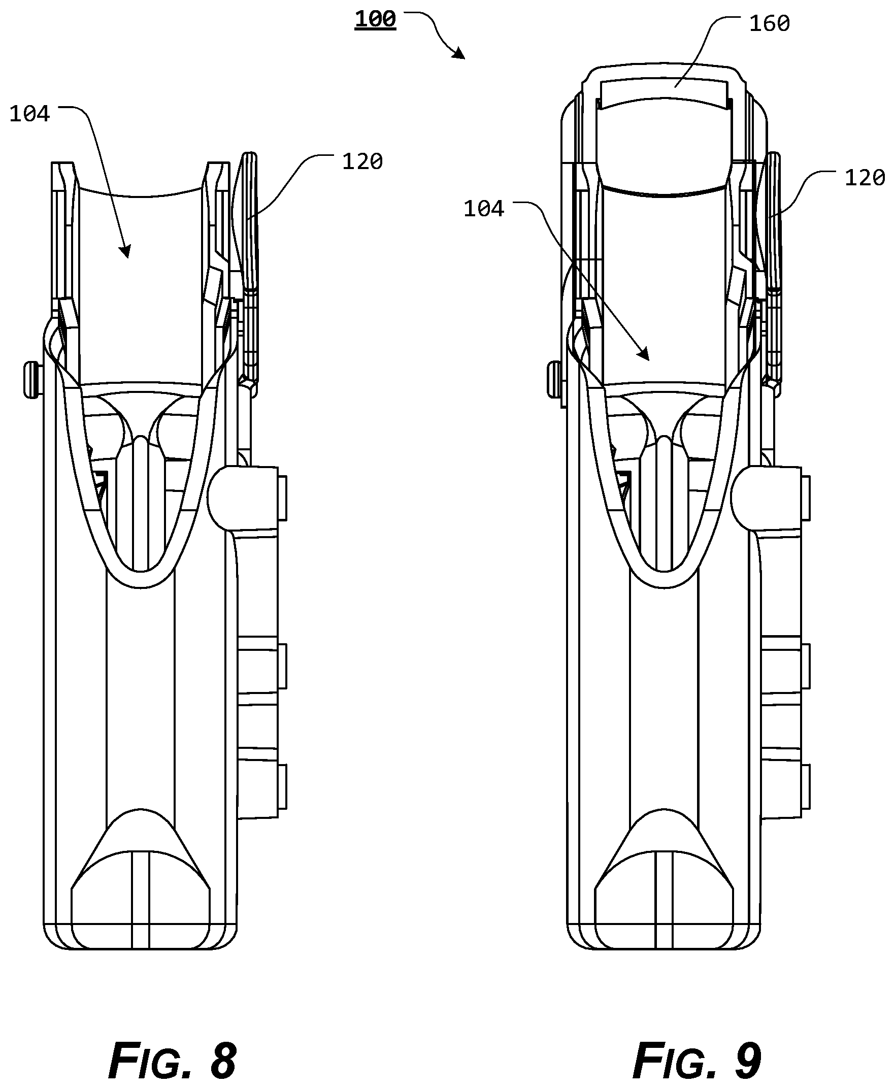
11. The holster of claim 10, wherein said at least partial holster cavity includes a holster frame top portion and a holster frame bottom portion.
12. The holster of claim 10, wherein said at least partial holster cavity includes a holster slide portion and a holster trigger guard portion.
13. The holster of claim 10, wherein said holster includes at least one holster frame attachment portion, which provides one or more areas, portions, or devices for fastening said holster to a belt loop or other holster holding device.
14. The holster of claim 10, wherein said release lever is pivotally connected to said holster body, via said release lever pivot pin, so that said release lever is repeatably pivotable between said retention position and said release position.
15. The holster of claim 10, wherein a release lever pivot pin may extend either all or part of said way across a release lever extension portion, joining said thumb/finger engagement portion and said locking engagement portion.
16. The holster of claim 10, wherein said handgun locking portion includes a substantially planar portion having a substantially planar surface formed so as to extend into at least a portion of said ejection port of an inserted handgun and engage a surface of said ejection port.
17. A holster for a handgun, comprising: a holster body defining an at least partial holster cavity; and a release lever pivotably attached or coupled to said holster body, wherein said release lever is repeatably pivotable between a retention position and a release position, and wherein said release lever is capable of being pivoted to said release position when a pivoting force is applied to said release lever, wherein if said release lever is in said retention position, at least a portion of a handgun locking portion of said release lever is positioned so as to extend through an aperture in a wall portion of said holster body, and protrude into a portion of said holster cavity a sufficient distance to engage at least a portion of an ejection port of an inserted handgun, and wherein if said release lever in said release position, said handgun locking portion is withdrawn from said holster cavity a sufficient distance to disengage from said ejection port of said handgun to allow said handgun to be withdrawn from said holster cavity.
18. The holster of claim 17, wherein said holster includes at least one holster frame attachment portion, which provides one or more areas, portions, or devices for fastening said holster to a belt loop or other holster holding device.
19. The holster of claim 17, wherein said release lever is pivotally connected to said holster body, via said release lever pivot pin, so that said release lever is repeatably pivotable between said retention position and said release position.
20. The holster of claim 17, wherein a release lever pivot pin may extend either all or part of said way across a release lever extension portion, joining said thumb/finger engagement portion and said locking engagement portion.
Description
CROSS-REFERENCE TO RELATED APPLICATIONS
[0001] This patent application is a continuation-in-part of co-pending U.S. patent application Ser. No. 16/658,740, filed Oct. 21, 2019, which is a continuation of co-pending U.S. patent application Ser. No. 15/683,566, filed Aug. 22, 2017, now U.S. Pat. No. 10,451,382, which claims the benefit of U.S. Patent Application Ser. No. 62/378,648, filed Aug. 23, 2016, the disclosures of which are incorporated herein by reference in their entireties.
STATEMENT REGARDING FEDERALLY SPONSORED RESEARCH OR DEVELOPMENT
[0002] Not Applicable.
REFERENCE TO SEQUENCE LISTING, A TABLE, OR A COMPUTER PROGRAM LISTING COMPACT DISC APPENDIX
[0003] Not Applicable.
NOTICE OF COPYRIGHTED MATERIAL
[0004] The disclosure of this patent document contains material that is subject to copyright protection. The copyright owner has no objection to the reproduction by anyone of the patent document or the patent disclosure, as it appears in the Patent and Trademark Office patent file or records, but otherwise reserves all copyright rights whatsoever. Unless otherwise noted, all trademarks and service marks identified herein are owned by the applicant.
BACKGROUND OF THE PRESENT DISCLOSURE
1. Field of the Present Disclosure
[0005] The present disclosure relates generally to the field of holsters. More specifically, the presently disclosed systems, methods, and/or apparatuses relate to a locking holster adaptable to be used with a handgun or other firearm.
2. Description of Related Art
[0006] It is generally known to carry a handgun in a holster designed to protect the handgun and hold it securely. Holsters can be worn in a number of ways, such as on a belt at the waist, on the thigh, attached or coupled to a plate carrier or tactical vest, under an arm, or around an ankle.
[0007] In certain instances, a handgun must be secured or retained within the holster, but quickly and easily removed from the holster, regardless of the type of holster used. Additionally, users need to be assured that, when not in use, the handgun will remain safely in the holster.
[0008] Some holsters rely solely on friction to secure the handgun in place. This combination might not be suitable for situations where the gun/holster is subject to a great deal of movement because such movement could cause the handgun to lose frictional engagement with the holster.
[0009] Certain other holsters include a variety of strap or flap arrangements that prevent the removal of the firearm from the holster while the strap or flap is in place. With designs that rely on this method to retain a handgun, a user must first unfasten and/or rotate the strap/flap before the firearm can be withdrawn. Then, to re-secure the handgun in the holster once the handgun has been re-holstered, the user must physically refasten and/or rotate the strap/flap before the firearm is securely retained within the holster. Some users might not prefer these designs because of the time required to release and/or re-secure the handgun.
[0010] Still other types of holsters include a release lever that is pivotably attached or coupled to the holster body so as to pivot, about a pivot pin or fulcrum point, between a locked position, wherein a protrusion from the release lever is capable of engaging a portion of the handguns trigger guard, and an unlocked position, wherein the release lever is pivoted such that the protrusion is removed from the portion of the handguns trigger guard, to allow the handgun to be withdrawn from the holster.
[0011] Any discussion of documents, acts, materials, devices, articles, or the like, which has been included in the present specification is not to be taken as an admission that any or all of these matters form part of the prior art base or were common general knowledge in the field relevant to the present disclosure as it existed before the priority date of each claim of this application.
BRIEF SUMMARY OF THE PRESENT DISCLOSURE
[0012] However, the typical locking holster arrangements have various shortcomings.
[0013] In order to overcome the shortcomings of the currently known holster arrangements and/or to provide an improved holster, in various exemplary, non-limiting embodiments, the holster of the present disclosure comprises at least some of a holster body defining an at least partial holster cavity; a hood pivotably attached or coupled to the holster body, wherein the hood is repeatably pivotable between a closed position and an open position, wherein the hood is biased to the open position via interaction between a holster/hood biasing element attached or coupled between a portion of the holster body and a portion of the hood; and a release lever pivotably attached or coupled to the holster body, wherein the release lever is repeatably pivotable between a retention position and a release position, wherein the release lever is biased to the retention position via interaction between a holster/lever biasing element attached or coupled to a portion of the holster body, and wherein the release lever is capable of being pivoted to the release position when a pivoting force is applied to the release lever, wherein if the release lever is in the retention position, at least a portion of a handgun locking portion of the release lever is positioned so as to extend through an aperture in a wall portion of the holster body, and protrude into a portion of the holster cavity a sufficient distance to engage at least a portion of an ejection port of an inserted handgun, and wherein if the release lever in the release position, the handgun locking portion is withdrawn from the holster cavity a sufficient distance to disengage from the ejection port of the handgun to allow the handgun to be withdrawn from the holster cavity, wherein if the hood is in the closed position and the release lever is in the retention position, a tab of the holster/lever biasing element protrudes into at least a portion of a hood locking recess of the hood, thereby maintaining the hood in the closed position, and wherein if the bias of the release lever is overcome and the release lever is pivoted from the retention position to the release position, the tab disengages from the hood locking recess and the hood is allowed to pivot to the open position.
[0014] In various exemplary, non-limiting embodiments, if the hood is in the open position, the hood does not hinder the handgun from being withdrawn from the holster.
[0015] In various exemplary, non-limiting embodiments, the at least partial holster cavity includes a holster frame top portion and a holster frame bottom portion.
[0016] In various exemplary, non-limiting embodiments, the at least partial holster cavity includes a holster slide portion and a holster trigger guard portion.
[0017] In various exemplary, non-limiting embodiments, the holster includes at least one holster frame attachment portion, which provides one or more areas, portions, or devices for fastening the holster to a belt loop or other holster holding device.
[0018] In various exemplary, non-limiting embodiments, the hood comprises a hood pivot stop, which corresponds to a hood stop surface formed in a surface portion of the holster body such that the hood pivot stop and the hood stop surface are aligned such that if the hood pivots towards the open position, the hood pivot stop contacts the hood stop surface to stop further rotation of the hood relative to the holster body.
[0019] In various exemplary, non-limiting embodiments, the release lever is pivotally connected to the holster body, via the release lever pivot pin, so that the release lever is repeatably pivotable between the retention position and the release position.
[0020] In various exemplary, non-limiting embodiments, a release lever pivot pin may extend either all or part of the way across a release lever extension portion, joining the thumb/finger engagement portion and the locking engagement portion.
[0021] In various exemplary, non-limiting embodiments, the handgun locking portion includes a substantially planar portion having a substantially planar surface formed so as to extend into at least a portion of the ejection port of an inserted handgun and engage a surface of the ejection port.
[0022] In various exemplary, non-limiting embodiments, the holster of the present disclosure comprises at least some of a holster body defining an at least partial holster cavity; and a release lever pivotably attached or coupled to the holster body, wherein the release lever is repeatably pivotable between a retention position and a release position, wherein the release lever is biased to the retention position via interaction between a holster/lever biasing element attached or coupled to a portion of the holster body, and wherein the release lever is capable of being pivoted to the release position when a pivoting force is applied to the release lever, wherein if the release lever is in the retention position, at least a portion of a handgun locking portion of the release lever is positioned so as to extend through an aperture in a wall portion of the holster body, and protrude into a portion of the holster cavity a sufficient distance to engage at least a portion of an ejection port of an inserted handgun, and wherein if the release lever in the release position, the handgun locking portion is withdrawn from the holster cavity a sufficient distance to disengage from the ejection port of the handgun to allow the handgun to be withdrawn from the holster cavity.
[0023] In various exemplary, non-limiting embodiments, the at least partial holster cavity includes a holster frame top portion and a holster frame bottom portion.
[0024] In various exemplary, non-limiting embodiments, the at least partial holster cavity includes a holster slide portion and a holster trigger guard portion.
[0025] In various exemplary, non-limiting embodiments, the holster includes at least one holster frame attachment portion, which provides one or more areas, portions, or devices for fastening the holster to a belt loop or other holster holding device.
[0026] In various exemplary, non-limiting embodiments, the release lever is pivotally connected to the holster body, via the release lever pivot pin, so that the release lever is repeatably pivotable between the retention position and the release position.
[0027] In various exemplary, non-limiting embodiments, a release lever pivot pin may extend either all or part of the way across a release lever extension portion, joining the thumb/finger engagement portion and the locking engagement portion.
[0028] In various exemplary, non-limiting embodiments, the handgun locking portion includes a substantially planar portion having a substantially planar surface formed so as to extend into at least a portion of the ejection port of an inserted handgun and engage a surface of the ejection port.
[0029] In various exemplary, non-limiting embodiments, the holster of the present disclosure comprises at least some of a holster body defining an at least partial holster cavity; and a release lever pivotably attached or coupled to the holster body, wherein the release lever is repeatably pivotable between a retention position and a release position, and wherein the release lever is capable of being pivoted to the release position when a pivoting force is applied to the release lever, wherein if the release lever is in the retention position, at least a portion of a handgun locking portion of the release lever is positioned so as to extend through an aperture in a wall portion of the holster body, and protrude into a portion of the holster cavity a sufficient distance to engage at least a portion of an ejection port of an inserted handgun, and wherein if the release lever in the release position, the handgun locking portion is withdrawn from the holster cavity a sufficient distance to disengage from the ejection port of the handgun to allow the handgun to be withdrawn from the holster cavity.
[0030] Accordingly, the holster of the present disclosure separately and optionally provides a quick-release handgun holster.
[0031] The holster of the present disclosure separately and optionally provides a handgun holster, which is capable of retaining a handgun securely in the holster while permitting a release of the handgun when the user requires.
[0032] The holster of the present disclosure separately and optionally provides a handgun holster, which is simple to operate.
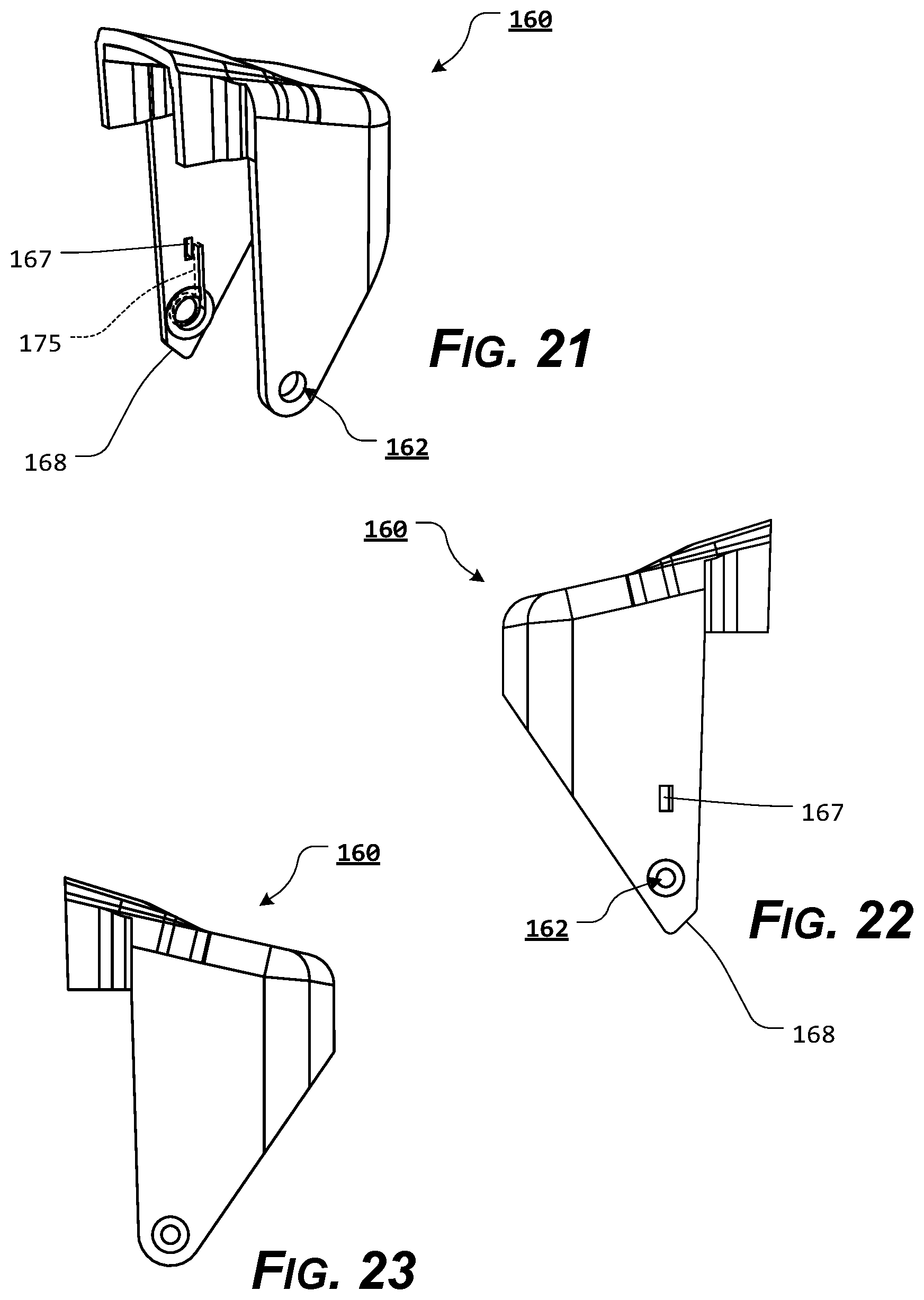
[0033] The holster of the present disclosure separately and optionally provides a handgun holster, which secures the handgun in the holster upon seating of the handgun in the holster, without requiring any additional operation by the user.
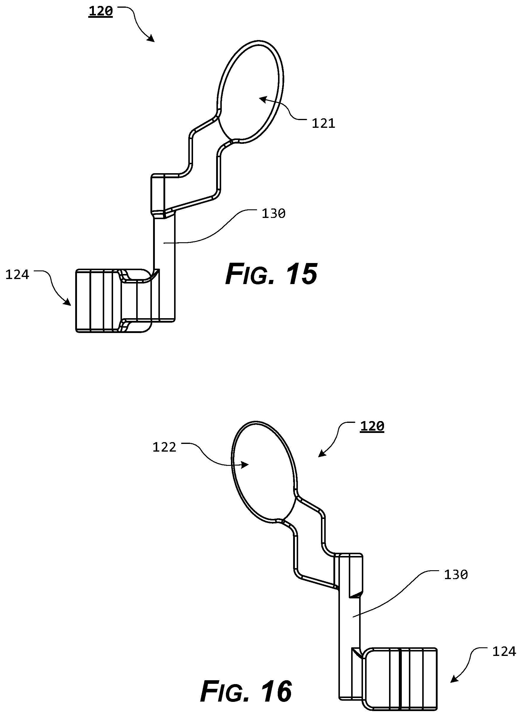
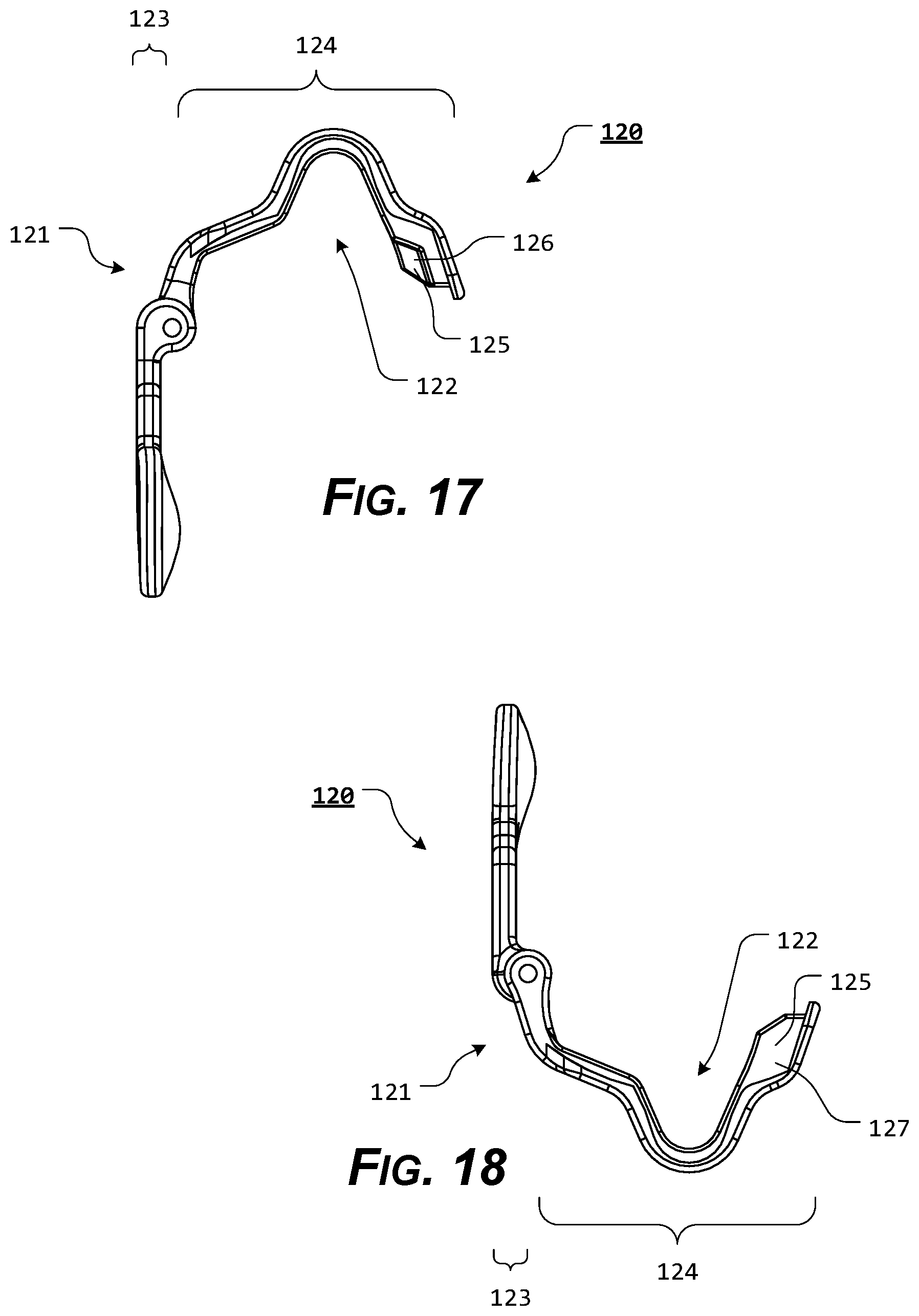
[0034] The holster of the present disclosure separately and optionally provides a handgun holster, which utilizes a firearm locking portion to engage at least a portion of an ejection port of an inserted handgun.
[0035] The presently disclosed systems, methods, and/or apparatuses separately and optionally provide a holster that can be easily manipulated by a user.
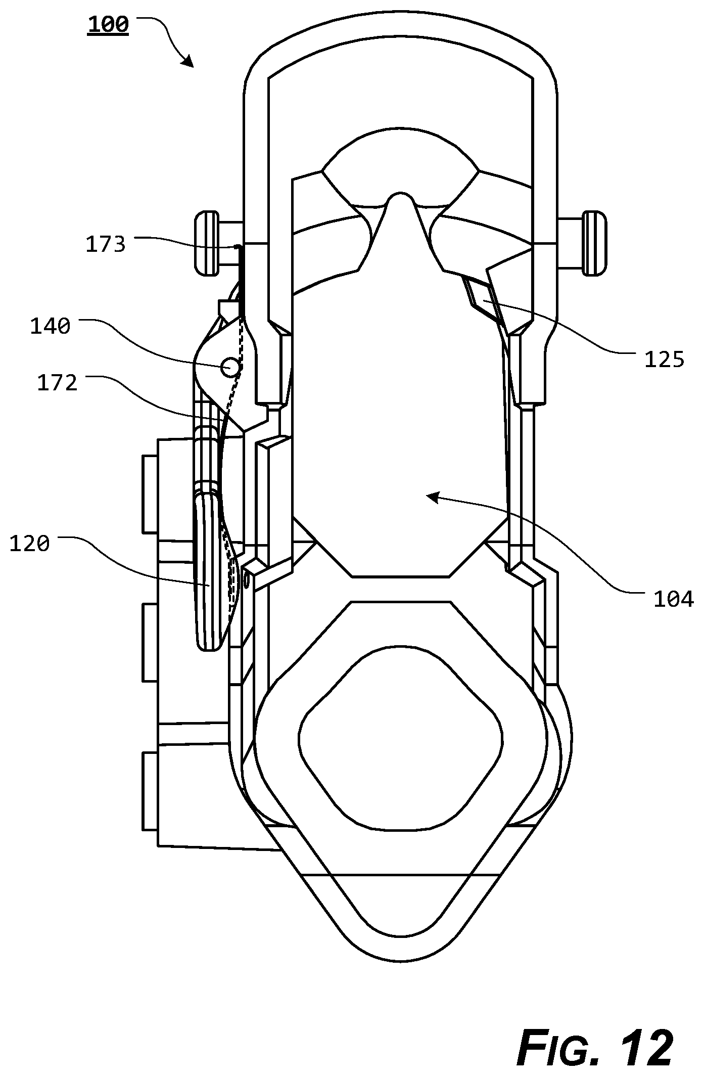
[0036] These and other aspects, features, and advantages of the presently disclosed systems, methods, and/or apparatuses are described in or are apparent from the following detailed description of the exemplary, non-limiting embodiments of the presently disclosed systems, methods, and/or apparatuses and the accompanying figures. Other aspects and features of embodiments of the presently disclosed systems, methods, and/or apparatuses will become apparent to those of ordinary skill in the art upon reviewing the following description of specific, exemplary embodiments of the presently disclosed systems, methods, and/or apparatuses in concert with the figures. While features of the presently disclosed systems, methods, and/or apparatuses may be discussed relative to certain embodiments and figures, all embodiments of the presently disclosed systems, methods, and/or apparatuses can include one or more of the features discussed herein. Further, while one or more embodiments may be discussed as having certain advantageous features, one or more of such features may also be used with the various embodiments of the systems, methods, and/or apparatuses discussed herein. In similar fashion, while exemplary embodiments may be discussed below as device, system, or method embodiments, it is to be understood that such exemplary embodiments can be implemented in various devices, systems, and methods of the presently disclosed systems, methods, and/or apparatuses.
[0037] Any benefits, advantages, or solutions to problems that are described herein with regard to specific embodiments are not intended to be construed as a critical, required, or essential feature(s) or element(s) of the presently disclosed systems, methods, and/or apparatuses of the claims.
BRIEF DESCRIPTION OF THE SEVERAL VIEWS OF THE DRAWINGS
[0038] As required, detailed exemplary embodiments of the presently disclosed systems, methods, and/or apparatuses are disclosed herein; however, it is to be understood that the disclosed embodiments are merely exemplary of the presently disclosed systems, methods, and/or apparatuses that may be embodied in various and alternative forms, within the scope of the presently disclosed systems, methods, and/or apparatuses. The figures are not necessarily to scale; some features may be exaggerated or minimized to illustrate details of particular components. Therefore, specific structural and functional details disclosed herein are not to be interpreted as limiting, but merely as a basis for the claims and as a representative basis for teaching one skilled in the art to employ the presently disclosed systems, methods, and/or apparatuses.
[0039] The exemplary embodiments of the presently disclosed systems, methods, and/or apparatuses will be described in detail, with reference to the following figures, wherein like reference numerals refer to like parts throughout the several views, and wherein:
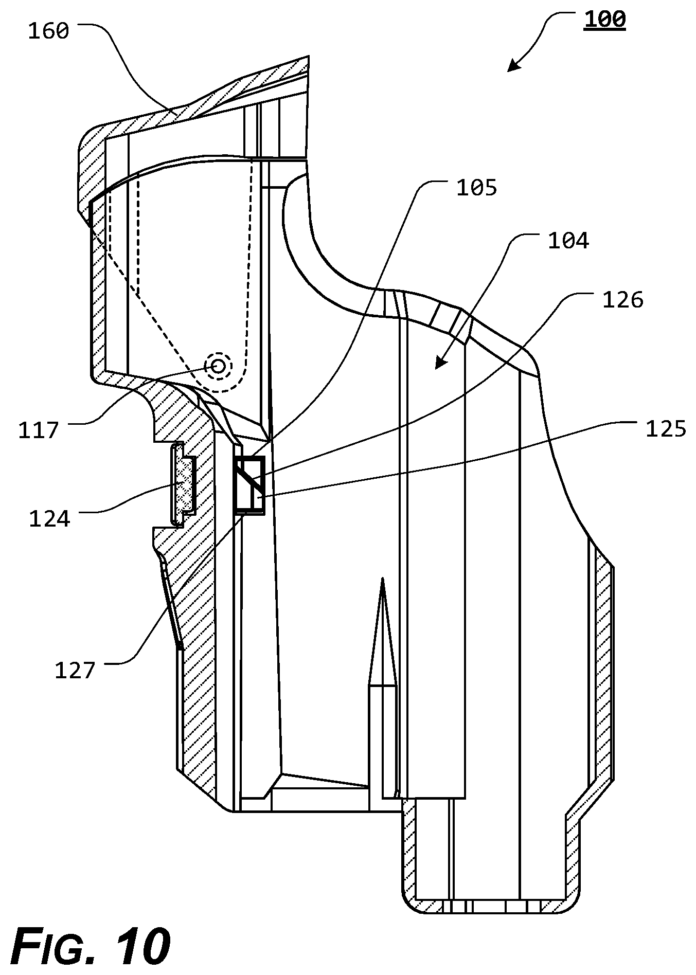
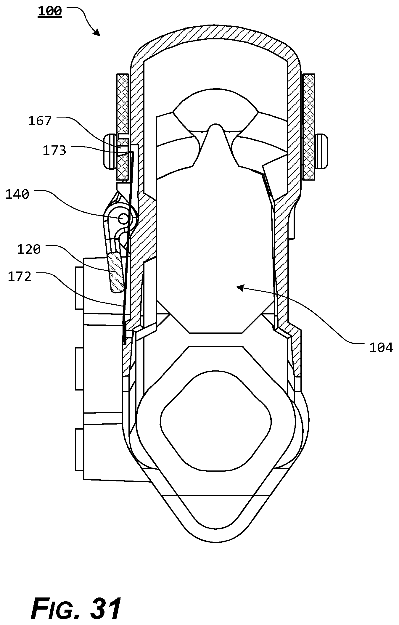
[0040] FIG. 1 illustrates a front, perspective view of an exemplary embodiment of a holster, according to the present disclosure;
[0041] FIG. 2 illustrates a rear, perspective view of an exemplary embodiment of a holster body, according to the present disclosure;
[0042] FIG. 3 illustrates a rear, perspective view of an exemplary embodiment of a holster, according to the present disclosure;
[0043] FIG. 4 illustrates a side view of an exemplary embodiment of a holster body, according to the present disclosure;
[0044] FIG. 5 illustrates a side view of an exemplary embodiment of a holster body, according to the present disclosure;
[0045] FIG. 6 illustrates a front view of an exemplary embodiment of a holster body, according to the present disclosure;
[0046] FIG. 7 illustrates a front view of an exemplary embodiment of a holster body, according to the present disclosure;
[0047] FIG. 8 illustrates a rear view of an exemplary embodiment of a holster body, according to the present disclosure;
[0048] FIG. 9 illustrates a rear view of an exemplary embodiment of a holster body, according to the present disclosure;
[0049] FIG. 10 illustrates a side, cross-sectional view of an exemplary embodiment of a holster body, according to the present disclosure;
[0050] FIG. 11 illustrates a side, cross-sectional view of an exemplary embodiment of a holster body, according to the present disclosure;
[0051] FIG. 12 illustrates a top view of an exemplary embodiment of a holster body, according to the present disclosure;
[0052] FIG. 13 illustrates a lower, rear perspective view of an exemplary embodiment of a release lever, according to the present disclosure;
[0053] FIG. 14 illustrates an upper, rear perspective view of an exemplary embodiment of a release lever, according to the present disclosure;
[0054] FIG. 15 illustrates a first side view of an exemplary embodiment of a release lever, according to the present disclosure;
[0055] FIG. 16 illustrates a second side view of an exemplary embodiment of a release lever, according to the present disclosure;
[0056] FIG. 17 illustrates a top view of an exemplary embodiment of a release lever, according to the present disclosure;
[0057] FIG. 18 illustrates a bottom view of an exemplary embodiment of a release lever, according to the present disclosure;
[0058] FIG. 19 illustrates a top, cross-sectional view of an exemplary embodiment of a holster, wherein the release lever is in a retention position, according to the present disclosure;
[0059] FIG. 20 illustrates a top, cross-sectional view of an exemplary embodiment of a holster, wherein the release lever is in a release position, according to the present disclosure;
[0060] FIG. 21 illustrates an upper, rear, perspective view of an exemplary embodiment of a hood, according to the present disclosure;
[0061] FIG. 22 illustrates a side view of an exemplary embodiment of a hood, according to the present disclosure;
[0062] FIG. 23 illustrates a side view of an exemplary embodiment of a hood, according to the present disclosure;
[0063] FIG. 24 illustrates a front view of an exemplary embodiment of a hood, according to the present disclosure;
[0064] FIG. 25 illustrates a rear view of an exemplary embodiment of a hood, according to the present disclosure;
[0065] FIG. 26 illustrates an upper, perspective view of an exemplary embodiment of a holster/hood biasing element, according to the present disclosure;
[0066] FIG. 27 illustrates a front view of an exemplary embodiment of a holster/hood biasing element, according to the present disclosure;
[0067] FIG. 28 illustrates a side view of an exemplary embodiment of a holster/hood biasing element, according to the present disclosure;
[0068] FIG. 29 illustrates a side view of an exemplary embodiment of a holster/lever biasing element, according to the present disclosure;
[0069] FIG. 30 illustrates a top, cross-sectional view of an exemplary embodiment of a holster, wherein the release lever is in a retention position, according to the present disclosure;
[0070] FIG. 31 illustrates a top, cross-sectional view of an exemplary embodiment of a holster, wherein the release lever is in a release position, according to the present disclosure; and
[0071] FIG. 32 illustrates a first side view of an exemplary embodiment of a holster, wherein the hood is in an open position and an exemplary handgun is aligned with the holster, according to the present disclosure.
DETAILED DESCRIPTION OF EXEMPLARY EMBODIMENTS OF THE PRESENT DISCLOSURE
[0072] For simplicity and clarification, the design factors and operating principles of the holster according to the presently disclosed systems, methods, and/or apparatuses are explained with reference to various exemplary embodiments of a holster according to the presently disclosed systems, methods, and/or apparatuses. The basic explanation of the design factors and operating principles of the holster is applicable for the understanding, design, and operation of the holster of the presently disclosed systems, methods, and/or apparatuses. It should be appreciated that the holster can be adapted to many applications where a holster can be used.
[0073] As used herein, the word "may" is meant to convey a permissive sense (i.e., meaning "having the potential to"), rather than a mandatory sense (i.e., meaning "must"). Unless stated otherwise, terms such as "first" and "second" are used to arbitrarily distinguish between the exemplary embodiments and/or elements such terms describe. Thus, these terms are not necessarily intended to indicate temporal or other prioritization of such exemplary embodiments and/or elements.
[0074] The term "coupled", as used herein, is defined as connected, although not necessarily directly, and not necessarily mechanically. The terms "a" and "an" are defined as one or more unless stated otherwise.
[0075] Throughout this application, the terms "comprise" (and any form of comprise, such as "comprises" and "comprising"), "have" (and any form of have, such as "has" and "having"), "include", (and any form of include, such as "includes" and "including") and "contain" (and any form of contain, such as "contains" and "containing") are used as open-ended linking verbs. It will be understood that these terms are meant to imply the inclusion of a stated element, integer, step, or group of elements, integers, or steps, but not the exclusion of any other element, integer, step, or group of elements, integers, or steps. As a result, a system, method, or apparatus that "comprises", "has", "includes", or "contains" one or more elements possesses those one or more elements but is not limited to possessing only those one or more elements. Similarly, a method or process that "comprises", "has", "includes" or "contains" one or more operations possesses those one or more operations but is not limited to possessing only those one or more operations.
[0076] It should also be appreciated that the terms "handgun" and "holster" are used for a basic explanation and understanding of the operation of the systems, methods, and apparatuses of this invention. Therefore, the terms "handgun" and "holster" are not to be construed as limiting the systems, methods, and apparatuses of this invention.
[0077] Furthermore, it should be appreciated that, for simplicity and clarification, the embodiments of this invention will be described with reference to a semiautomatic-type handgun being secured within the holster of the present disclosure. However, it should be appreciated that the operating principles of the disclosed holster may also be employed to construct holsters or holders for any revolver or semiautomatic-type handgun, edged handguns as well as less than lethal products (i.e., tasers, pepper spray, mace canisters, or batons), so long as these items have an appropriate ledge or void that may be engaged or retained by a locking projection or other retaining means. Furthermore, it is also within the scope of the present invention that the present holster may be employed as a pouch for tactical accessories, such as ammunition magazines and/or flashlights, as well as for everyday items such as cell phones or personal digital assistants.
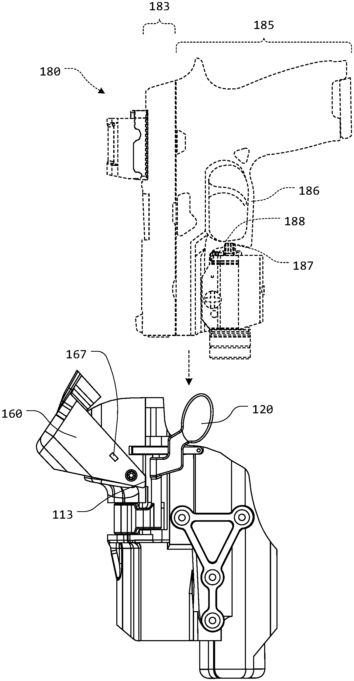
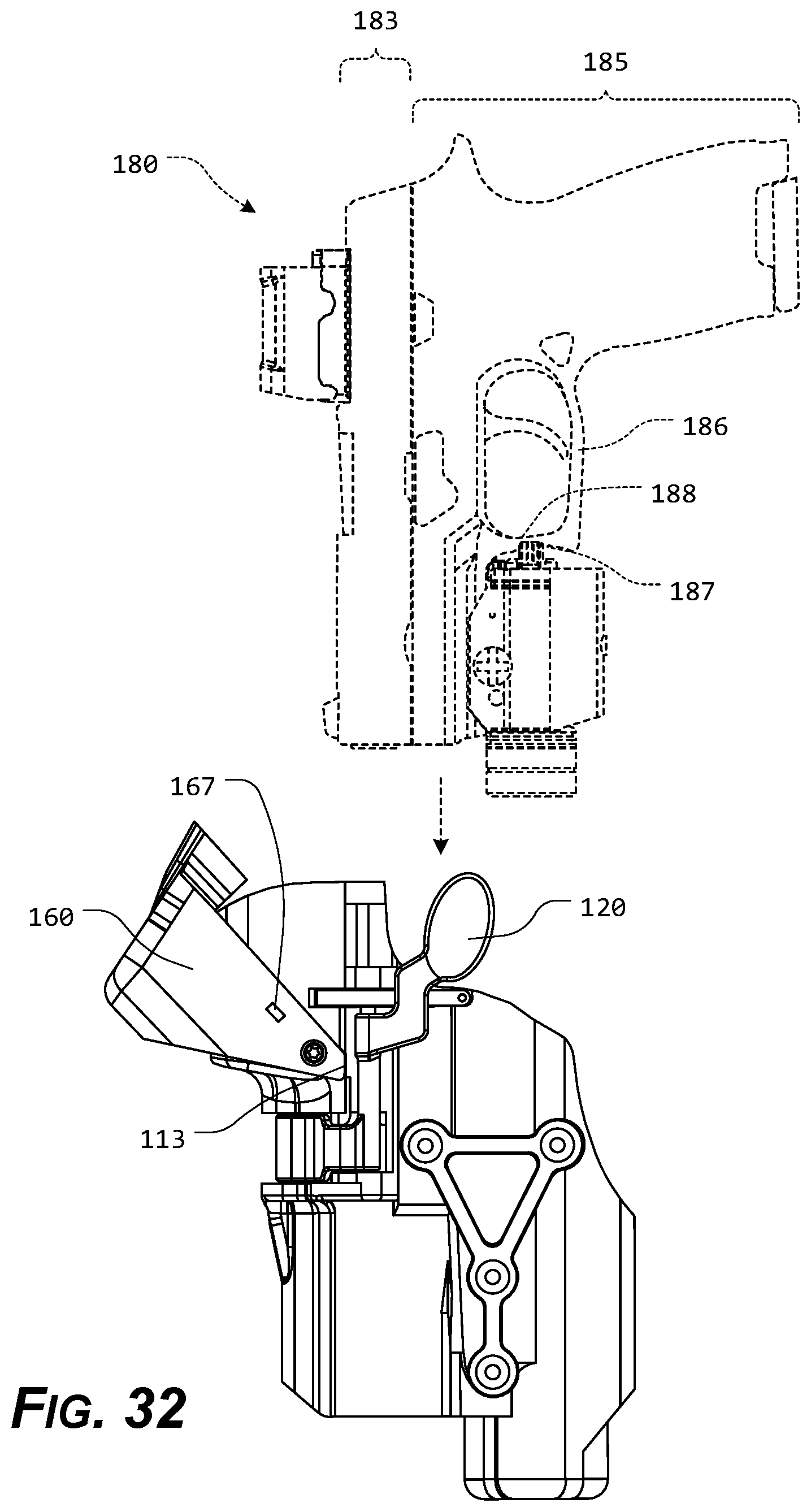
[0078] Turning now to the appended drawing figures, FIGS. 1-32 illustrate certain elements and/or aspects of a first, illustrative, non-limiting embodiment of a holster 100 according to the present disclosure. It should be appreciated that the holster 100 is adapted to retain an exemplary semiautomatic-type handgun 180. The semiautomatic-type handgun 180 generally includes a slide portion 183 and a frame portion 185. The slide portion 183 generally includes a barrel, while the frame portion 185 generally includes a dust cover, a grip, a trigger guard 186, and a trigger. The trigger guard 186 includes an outer surface 187, which defines the outer perimeter of the trigger guard 186 and an inner surface 188, which defines an area where the trigger is located and allows a user's finger access to the trigger.
[0079] An ejection port 184 is formed in a portion of the slide portion 183.
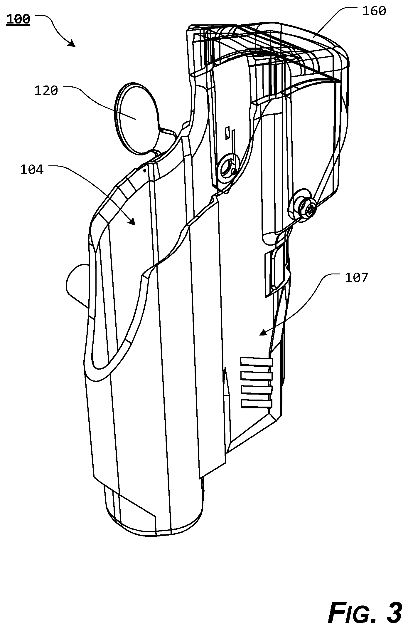
[0080] As illustrated in FIGS. 1-32, the holster 100 includes a holster body 103 defining a holster cavity 104 for receiving and holding at least a portion of the handgun 180. The holster cavity 104 may be formed from any number or combination of walls, including, for example, a single, continuous wall or multiple coupled or joined walls. Alternatively, the holster cavity 104 may be formed by a material shaped or bent in a substantial "U" shape. Thus, the holster cavity 104 may be formed by any holster cavity, space, or platform that is capable of retaining an appropriate portion of the handgun 180.
[0081] In various exemplary embodiments, the holster body 103 comprises at least some of a pair of opposed wall portions comprising a first wall portion 106 and a second wall portion 107. Typically, the first wall portion 106 is considered the inner side of the holster 100 and is worn against or adjacent the user's body, while the second wall portion 107 is considered the outer side of the holster 100 and is worn away from the user's body.
[0082] The holster body 103 may further comprise at least some of a fourth wall portion 109 and a third wall portion 108. Optionally, the fourth wall portion 109 and the third wall portion 108 may comprise extended portions of the first wall portion 106 and the second wall portion 107.
[0083] It should also be appreciated that the holster 100 may be formed such that one or more of the first wall portion 106, the second wall portion 107, the fourth wall portion 109, and/or the third wall portion 108 is/are sufficient to define the holster cavity 104 for receiving the handgun 180 and the remaining wall portions are not included.
[0084] It should be noted that the walls of the holster 100 may be substantially planar. Alternatively, the walls of the holster 100 may be contoured or shaped to better accommodate a specific type or model of handgun 180 (or other item) to be retained within the holster 100.
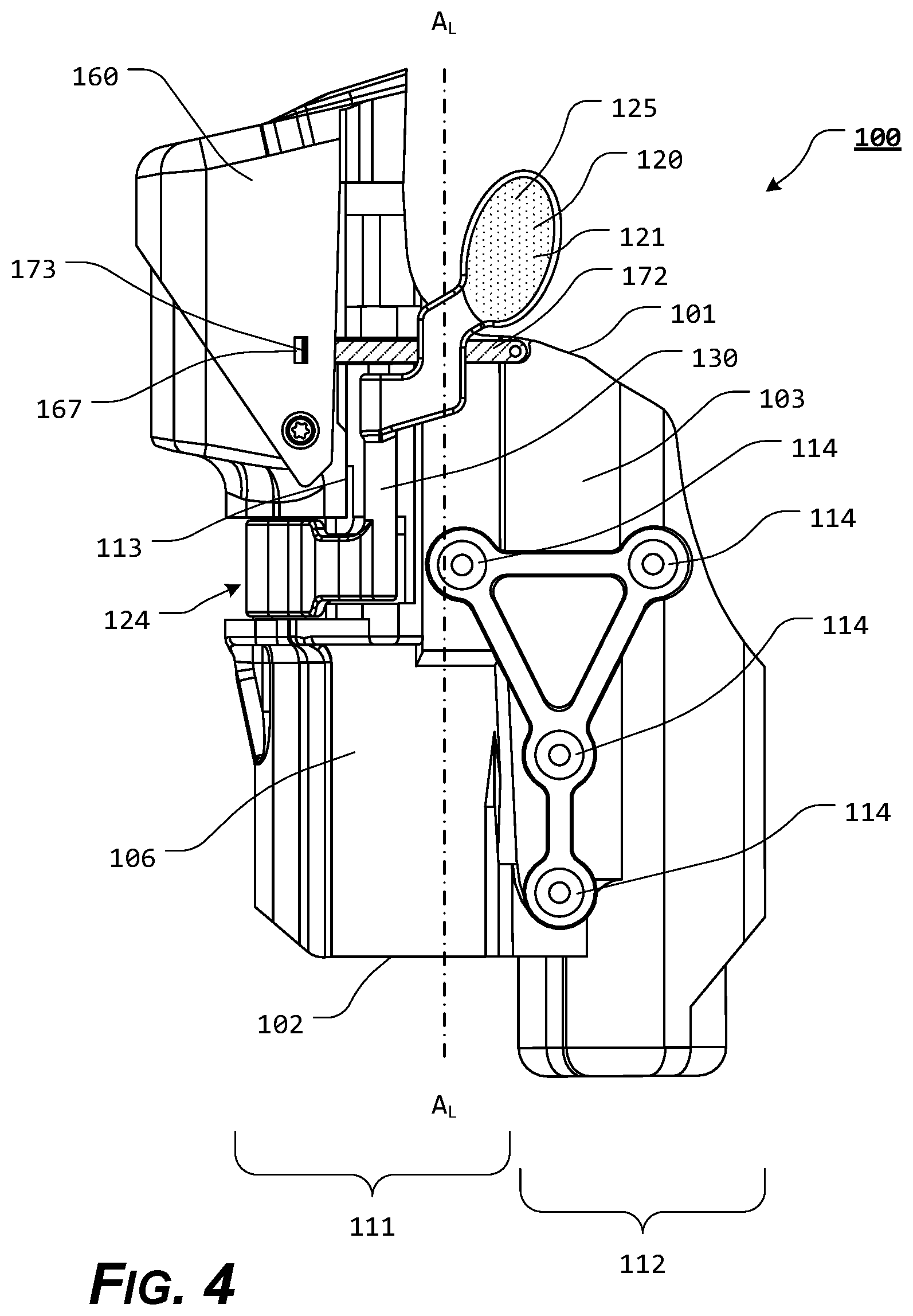
[0085] The at least partial holster cavity 104 includes a holster frame top portion 101 and a holster frame bottom portion 102 and may be formed from any number or combination of wall portions, including, for example, a single, continuous wall portion or multiple coupled or joined wall portions. Thus, the holster cavity 104 may be formed by any cavity, partial cavity, space, or platform that is capable of retaining a handgun 180.
[0086] In certain exemplary, nonlimiting embodiments, the holster body 103 merely comprises a single wall portion, such as, for example, the first wall portion 106. Any remaining portions of the holster 100 may be attached, coupled, or formed as a portion or extension of the first wall portion 106 and/or the holster body 103.
[0087] In certain exemplary, nonlimiting embodiments, as illustrated, the holster body 103 and/or the holster cavity 104 includes a holster slide portion 111 and a holster trigger guard portion 112. At least a portion of the holster trigger guard portion 112 is shaped to receive and accommodate at least a portion of the trigger guard 186 of an inserted handgun 180. In various exemplary embodiments, the holster trigger guard portion 112 is generally formed by a portion of the body of the holster 100. The holster trigger guard portion 112 is shaped generally to match the contours of at least a portion of the outer surface 187 of the trigger guard 186. The holster trigger guard portion 112 is formed to contact at least a portion of the outer surface 187 of the trigger guard 186 of the inserted handgun 180 and further limit how far the handgun 180 can be inserted into the holster 100.
[0088] The construction of the holster 100 further facilitates alignment of at least a portion of an ejection port 184 of the handgun 180 with at least a portion of the handgun locking portion 125 by limiting lateral movement of the handgun 180 with respect to the handgun locking portion 125 without preventing a user from easily holstering or drawing the handgun 180.
[0089] In various exemplary embodiments, the holster 100 optionally includes at least one holster frame attachment portion 114, which provides one or more areas, portions, or devices for fastening the holster 100 to a belt loop or other holster holding device. Alternatively, the means for holster frame attachment portion 114 may comprise a clip or hook adapted to, for example, be clipped over or to a belt. In further exemplary embodiments, the holster frame attachment portion 114 may comprise one or more quick-disconnect or other couplings, which may be permanently or removably coupled to corresponding and cooperating coupling(s) provided on a belt or other carrier or platform. In still other exemplary embodiments, the holster 100 may comprise an integral belt, or may comprise one or more connections for attachment to a chest, ankle, leg, shoulder, or other harness or band, or for otherwise securing the holster 100 to a user or the user's apparel.
[0090] The holster 100 may be formed of a substantially rigid material, such as, for example, a polymeric material or a polymeric composite. Alternate materials of construction may include one or more of the following: steel, aluminum, titanium, and/or other metals, as well as various alloys and composites thereof, glass-hardened polymers, polymer or fiber reinforced metals, carbon fiber or glass fiber composites, continuous fibers in combination with thermoset and thermoplastic resins, chopped glass or carbon fibers used for injection molding compounds, laminate glass or carbon fiber, epoxy laminates, woven glass fiber laminates, impregnate fibers, polyester resins, epoxy resins, phenolic resins, polyimide resins, cyanate resins, high-strength plastics, nylon, glass, or polymer fiber reinforced plastics, thermoform and/or thermoset sheet materials, or the like, and/or various combinations of the foregoing.
[0091] In various exemplary embodiments, at least certain components of the holster 100 may be formed of any known or later developed, substantially flexible material(s) such as a polymeric material, leather, foam, foam laminates, natural and man-made (synthetic) fabrics, natural and man-made (synthetic) fabric laminates, moldable honeycomb materials, or the like, and/or various combinations of the foregoing.
[0092] Thus, it should be understood that the material or materials used to form the holster 100 and/or various components of the holster 100 is a design choice based on the desired appearance and/or functionality of the holster 100.
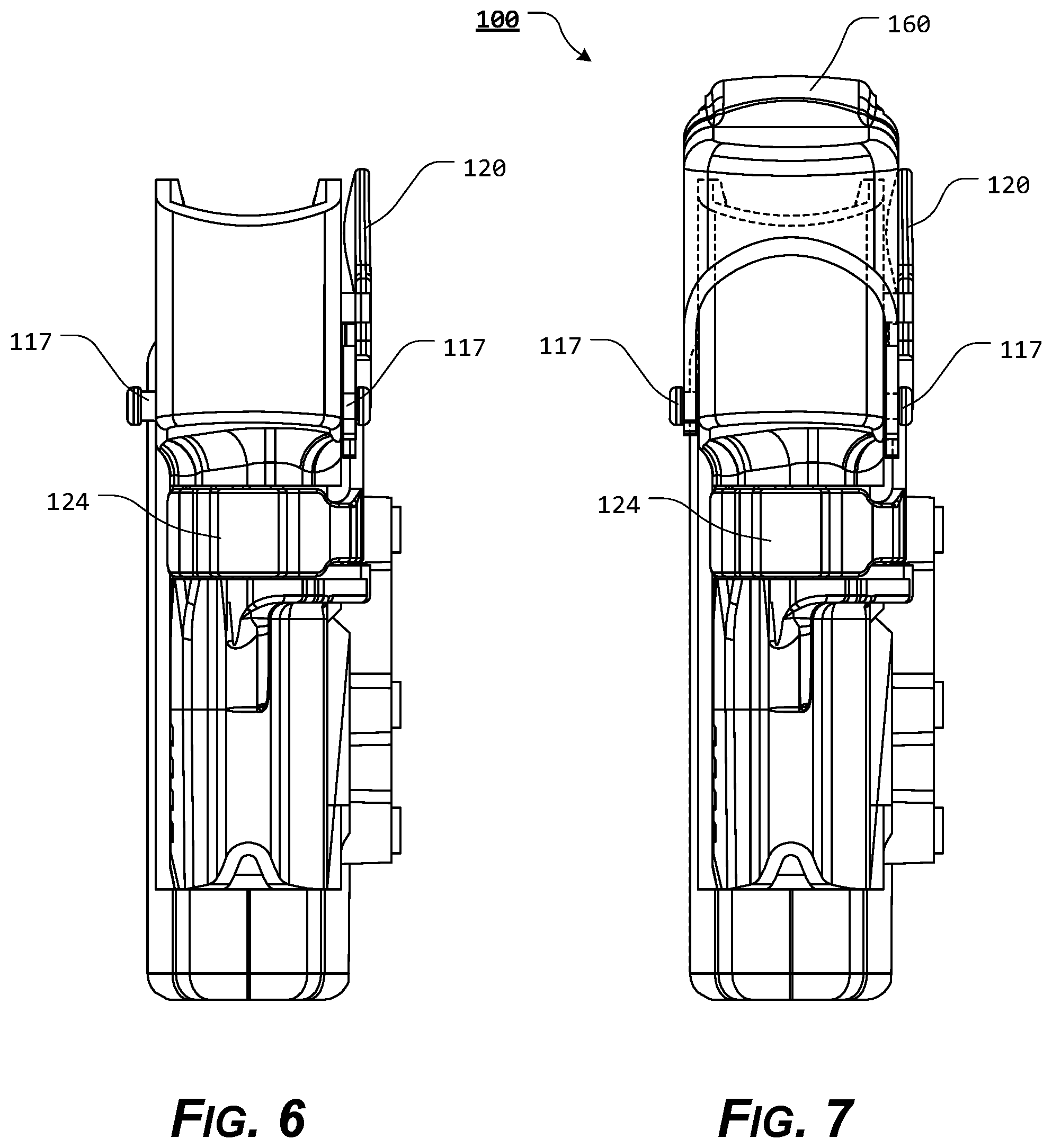
[0093] As further shown in FIGS. 1-32, the holster 100 includes a hood 160, pivotably coupled to the holster body 103, via interaction of hood pivot projections 117 and hood pivot pin apertures 162. As illustrated, for example, in FIGS. 4 and 32, the hood 160 is repeatably pivotable between a closed position for securing the handgun within the holster cavity 104 and an open position for insertion or removal of the handgun.
[0094] The hood 160 is pivotably coupled to the holster body 103, via interaction between hood pivot pin apertures 162 and hood pivot projections 117. In various exemplary embodiments, the hood 160 is pivotably coupled, via the hood pivot projections 117, to opposing portions of the first wall portion 106 and the second wall portion 107. Alternatively, the hood 160 may be pivotably coupled, via the hood pivot projections 117, to opposing portions of the fourth wall portion 109.
[0095] The hood 160 is biased, via the holster/hood biasing element 175, to the open position, whether the release lever 120 is in the retention position or the release position. In various exemplary embodiments, the holster/hood biasing element 175 comprises a biasing spring.
[0096] The holster/hood biasing element 175 is attached or coupled to or within a portion of the holster body 103 and two or within a portion of the hood 160.
[0097] When appropriately positioned relative to the hood 160 and the holster body 103, the holster/hood biasing element 175 biases or urges the hood 160 towards the open position.
[0098] In various exemplary embodiments, the hood 160 comprises a hood pivot stop 168, which corresponds to a hood stop surface 113 formed in a surface portion of the holster body 103. The hood pivot stop 168 and the hood stop surface 113 are aligned such that when the hood 160 pivots towards the open position, the hood pivot stop 168 contacts the hood stop surface 113 to stop further rotation of the hood 160, such that contact between the hood pivot stop 168 and the hood stop surface 113 defines an arc of rotation of the hood 160 relative to the holster body 103. As shown in the drawing figures, the hood 160 includes a first hood pivot stop 168, which corresponds to a hood stop surface 113 formed in the first wall portion 106. However, in various exemplary embodiments, the hood 160 comprises two hood pivot stops 168, each of which corresponds to a hood stop surface 113 formed in the holster body 103.
[0099] The release lever 120 includes a first side 121 facing generally outward from the holster 100, away from the holster cavity 104 formed by the holster 100, and a second side 122 facing toward the holster cavity 104 formed by the holster 100. The release lever 120 comprises at least some of a thumb/finger engagement portion 123 and a locking engagement portion 124. The thumb/finger engagement portion 123 and the locking engagement portion 124 are generally joined by a release lever extension portion 130.
[0100] The thumb/finger engagement portion 123 may be smooth and non-textured such that the thumb/finger engagement portion 123 will not impede the user's thumb/finger as the user's thumb/finger engages the surface of the thumb/finger engagement portion 123, establishes a grip on the frame portion 185 of the handgun 180, applies a pivoting force to the release lever 120, or pivots the release lever 120 to a release position. Alternatively, the first side 121 of the thumb/finger engagement portion 123 may include a textured portion 129 so that the user's thumb/finger does not easily slip off of the thumb/finger engagement portion 123 or so that the thumb/finger engagement portion 123 may be distinguished tactilely from other portions of the release lever 120 and/or the holster 100.
[0101] In various exemplary, non-limiting embodiments, the release lever 120 is pivotally connected to the first wall portion 106, via the release lever pivot pin 140, so that the release lever 120 is repeatably pivotable between a retention position and a release position. The release lever pivot pin 140 may be positioned substantially parallel to a longitudinal axis, A.sub.L, of the holster 100, substantially perpendicular to a longitudinal axis, A.sub.L, of the holster 100, at a substantially acute angle relative to a longitudinal axis, A.sub.L, of the holster 100, or at a substantially obtuse angle relative to a longitudinal axis, A.sub.L, of the holster 100. Thus, the release lever pivot pin 140 may be positioned at any angle relative to a longitudinal axis, A.sub.L, of the holster 100.
[0102] It should be appreciated that the release lever pivot pin 140 may extend either all or part of the way across the release lever extension portion 130 and/or the release lever 120.
[0103] In certain exemplary embodiments, the release lever 120 may include one or more protrusions that replace the release lever pivot pin 140 and extend from the release lever 120. Corresponding indentions, indentations, notches, grooves, or dimples may be formed in the first wall portion 106. In these exemplary embodiments, the protrusions are formed so as to operate in cooperating relationship with the first and second dimples such that the release lever 120 may be pivotally attached, via the protrusions and the dimples, to the first wall portion 106 approximately between a thumb/finger engagement portion 123 and the locking engagement portion 124. Thus, the release lever 120 is able to snap fit into the first wall portion 106.
[0104] Alternatively, the positions of the protrusions and the first and second may be reversed, such that the release lever 120 may include dimples while the first wall portion 106 includes protrusions. In these exemplary embodiments, the dimples are formed so as to operate in cooperating relationship with the protrusions such that the release lever 120 may be pivotably attached, via the dimples and the protrusions, to the first wall portion 106 approximately between the thumb/finger engagement portion 123 and the locking engagement portion 124.
[0105] While FIGS. 1-32 show the release lever 120 coupled to the first wall portion 106, it should be appreciated that in various exemplary embodiments, the release lever 120 may be coupled to the second wall portion 107.
[0106] The locking engagement portion 124 includes a handgun locking portion 125 formed of a protrusion on the second side 122 of the locking engagement portion 124. The release lever 120 is pivotable between a retention position and a release position. When the release lever 120 is in the retention position, at least a portion of the handgun locking portion 125 is positioned so as to extend through an aperture 105 in the first wall portion 106 of the holster body 103 and protrude into a portion of the holster cavity 104 a sufficient distance to engage at least a portion of the ejection port 184 of the handgun 180 appropriately seated within the holster cavity 104. When the release lever 120 in the release position, the handgun locking portion 125 is withdrawn from the holster cavity 104, through the aperture 105, a sufficient distance to disengage from the ejection port 184 of the handgun 180 appropriately seated within the holster cavity 104 to allow the handgun 180 to be withdrawn from the holster cavity 104.
[0107] The handgun locking portion 125 includes a substantially planar portion 127 having a substantially planar surface facing toward the holster frame bottom portion 102. The substantially planar portion 127 is generally formed so as to extend into at least a portion of the ejection port 184 of an inserted handgun 180 and engage a surface of the ejection port 184. In this manner, when the release lever 120 is in the retention position, the substantially planar portion 127 of the handgun locking portion 125 extends into at least a portion of the ejection port 184 of an inserted handgun 180 and contacts a surface of the ejection port 184 and resists a withdrawing force applied to the handgun 180, maintaining the handgun 180 within the holster cavity 104.
[0108] When the release lever 120 is pivoted to the release position and the substantially planar portion 127 is withdrawn and does not contact a surface of the ejection port 184, the handgun 180 can be withdrawn from the holster cavity 104.
[0109] In various exemplary embodiments, a ramp portion 126 is included in a portion of the handgun locking portion 125 facing toward the holster frame top portion 101. The ramp portion 126 is generally formed so as to be contacted by a portion of the slide portion 183 or any other portion of an inserted handgun 180, as the handgun 180 is being inserted within the holster cavity 104, to urge the release lever 120 toward the release position as the handgun 180 is inserted within the holster cavity 104.
[0110] In certain exemplary embodiments, particularly those in which the ramp portion 126 is included, when the handgun 180 is returned to the holster cavity 104, the slide portion 183 or other portion of the inserted handgun 180 may contact the ramp portion 126 of the handgun locking portion 125 and displaces the handgun locking portion 125 sufficient to pivot the release lever 120 such that the substantially planar portion 127 of the handgun locking portion 125 is displaced relative to the holster cavity 104. Thus, the substantially planar portion 127 does not prohibit insertion of the handgun 180 into the holster cavity 104 and may no longer pivot the release lever 120 far enough to the release position that the hood locking portion 128 no longer blocks the hood 160 from being pivoted to the closed position.
[0111] Otherwise, if the ramp portion 126 is not included and/or the terminal end of the handgun locking portion 125 does not protrude far enough into the holster cavity 104 to contact the slide portion 183 or any other portion of an inserted handgun 180, the hood 160 cannot be moved to the closed position unless the user appropriately manipulates the release lever 120.
[0112] The release lever 120 is biased, via interaction between the holster/lever biasing element 172 and the release lever 120, to the retention position. In various exemplary embodiments, the holster/lever biasing element 172 comprise a portion of spring steel having a tab 173 extending from a distal portion of the holster/lever biasing element 172.
[0113] The holster/lever biasing element 172 is attached or coupled to or within a portion of the holster body 103. In certain exemplary embodiments, the holster/lever biasing element 172 is molded or embedded within a portion of the holster body 103.
[0114] The tab 173 is formed so as to interact with the hood locking recess 167, when the hood 160 is in the closed position and the release lever 120 is in the retention position, to maintain the hood 160 in the closed position.
[0115] When the release lever 120 is pivoted towards or to the release position, the hood tab 173 is withdrawn from the hood locking recess 167 a sufficient distance so as to disengage from the hood locking recess 167 and release the hood 160 and allow the hood 160 to pivot to the open position.
[0116] When the release lever 120 is in the retention position, the handgun locking portion 125 is positioned so as to extend through an aperture 105 in the first wall portion 106 of the holster body 103, into a portion of the holster cavity 104. When the hood 160 is in the closed position and the release lever 120 is in the retention position, the tab 173 protrudes into at least a portion of the hood locking recess 167 of the hood 160, thereby maintaining the hood 160 in the closed position.
[0117] In various exemplary embodiments, the hood locking recess 167 comprises a recess extending through a portion of the hood 160.
[0118] When the bias of the release lever 120 is overcome and the release lever 120 is pivoted from the retention position to the release position, the tab 173 disengages from the hood locking recess 167 and the hood 160 is allowed to pivot to the open position. When the hood 160 is in the open position, the hood 160 no longer interferes with a portion of the handgun 180 and no longer hinders the handgun 180 from being withdrawn from the holster 100.
[0119] As the release lever 120 continues to be pivoted towards the release position, the handgun locking portion 125 is withdrawn a sufficient distance from within the holster cavity 104 to disengage from the ejection port 183 of the handgun 180 and allow the handgun 180 to be removed from the holster 100.
[0120] When the hood 160 is in the open position and the pivoting force is removed from the release lever 120, the release lever 120 returns to the biased retention position.
[0121] In various illustrative, non-limiting embodiments of this invention, when the hood 160 is in the open position and the release lever 120 is in the retention position, the tab 173 is optionally positioned so as to block the hood 160 from being pivoted to the closed position. Thus, the release lever 120 must be rotated at least partially toward the release position to allow the hood 160 to be pivoted to the closed position.
[0122] It should be appreciated that if the release lever 120 has not been sufficiently pivoted towards the release position, the handgun 180 may not be removed from the holster 100 until the release lever 120 has been sufficiently pivoted towards the release position. Thus, in certain exemplary embodiments, as the release lever 120 is pivoted towards the release position, the tab 173 is first withdrawn from the hood locking recess 167, then, as the release lever 120 is pivoted further towards the release position, the handgun locking portion 125 locking portion 125 is withdrawn a sufficient distance from within the holster cavity 104 to allow the handgun 180 to be removed from the holster 100.
[0123] During use of the holster 100, the holster 100 is initially presented in an empty condition with the hood 160 biased to the open position.
[0124] During use or operation of the holster 100, as a user begins to holster a handgun 180 in the holster 100, the handgun 180 is inserted into the holster cavity 104 of the holster, muzzle first, and is guided into position by at least some of the first wall portion 106, the second wall portion 107, the fourth wall portion 109, and the third wall portion 108.
[0125] In certain exemplary embodiments, wherein the ramp portion 126 is included and the terminal end of the handgun locking portion 125 protrudes far enough into the holster cavity 104 to contact the slide portion 183 or another portion of an inserted handgun 180, as the handgun 180 is inserted further into the holster cavity 104, an outer surface of the handgun 180 contacts and rides along the terminal end of the handgun locking portion 125 and/or the ramp portion 126. When the handgun 180 is seated in the holster cavity 104, the ejection port 184 or another portion of an inserted handgun 180 passes a point of contact with the handgun locking portion 125 and at least a portion of the terminal end of the handgun locking portion 125 protrudes within the ejection port 184 of the handgun 180 a sufficient amount such that the substantially planar portion 127 engages a surface of the ejection port 184 to block the handgun 180 from being withdrawn from the holster cavity 104.
[0126] When the handgun 180 in seated in the holster cavity 104 the release lever 120 can be pivoted towards the release position to allow the hood 160 to be manually pivoted towards the closed position.
[0127] When the hood 160 is pivoted to the closed position, the tab 173 engages the hood locking recess 167 and the release lever 120 can be manually released and the bias of the release lever 120 causes the release lever 120 to return to the biased retention position.
[0128] When the hood 160 is in the closed position and the release lever 120 is biased to the retention position, the handgun locking portion 125 protrudes, from the release lever 120, through the aperture 105 of the holster body 103, and engages a defining surface of the ejection port 184 of the handgun 180.
[0129] Thus, the handgun 180 is secured in the holster cavity 104 of the holster 100 by operation of the handgun locking portion 125 engaging a portion of the ejection port 184 and interaction between the tab 173 and the hood locking recess 167 maintain the hood 160 in a closed position, thereby blocking removal of the handgun 180. While the handgun 180 is fully seated in the holster cavity 104, with the hood 160 maintained in the closed position, removal of the handgun 180 is not permitted, as of the tab 173 engages a portion of the ejection port 184 and the hood 160 covers at least a portion of the handgun 180 (i.e., the rear slide portion 183, the hammer, or the backstrap, depending on the type and model of handgun) and does not allow the handgun 180 to pass by.
[0130] In order to release and unholster the handgun 180, the user merely grasps the handgun 180 in a manner to establish a normal grip on the handgun 180. As the user's grip is established, the user's thumb contacts and applies pressure to the thumb/finger engagement portion 123, such that the bias of the release lever 120 is overcome and the release lever 120 is pivoted to a release position.
[0131] As the bias of the release lever 120 is overcome, the release lever 120 is pivoted to the release position and the tab 73 disengages from the hood locking recess 167, allowing the biasing force of the holster/hood biasing element 175 to pivot the hood 120 to the open position. As the release lever 120 is pivoted further toward the release position, the handgun locking portion 125 is withdrawn from the ejection port 184 of the handgun 180. When the release lever 120 is pivoted sufficiently such that the handgun locking portion 125 is sufficiently withdrawn from the holster cavity 104 to clear or disengage from the ejection port 184 of the handgun 180, a removal force may be applied to the handgun 180 and the handgun 180 may be removed from the holster 100.
[0132] When the handgun 180 has been removed from the holster 100, interaction between the holster/lever biasing element 172 release lever 120 bias the release lever 120 to the retention position.
[0133] The holster 100, as shown and described, is oriented such that the release lever 120 is generally accessible by the user's thumb. However, in various other exemplary embodiments, the release lever 120 may optionally be positioned so that it is generally accessible by one or more of the user's other fingers.
[0134] It should be appreciated that the holster 100 is generally illustrated as being a right-hand holster. However, the structure and/or elements of the holster 100 may be positioned so as to provide a left-hand holster.
[0135] While the presently disclosed systems, methods, and/or apparatuses has been described in conjunction with the exemplary embodiments outlined above, the foregoing description of exemplary embodiments of the presently disclosed systems, methods, and/or apparatuses, as set forth above, are intended to be illustrative, not limiting and the fundamental disclosed systems, methods, and/or apparatuses should not be considered to be necessarily so constrained. It is evident that the presently disclosed systems, methods, and/or apparatuses is not limited to the particular variation set forth and many alternatives, adaptations modifications, and/or variations will be apparent to those skilled in the art.
[0136] Furthermore, where a range of values is provided, it is understood that every intervening value, between the upper and lower limit of that range and any other stated or intervening value in that stated range is encompassed within the presently disclosed systems, methods, and/or apparatuses. The upper and lower limits of these smaller ranges may independently be included in the smaller ranges and is also encompassed within the presently disclosed systems, methods, and/or apparatuses, subject to any specifically excluded limit in the stated range. Where the stated range includes one or both of the limits, ranges excluding either or both of those included limits are also included in the presently disclosed systems, methods, and/or apparatuses.
[0137] It is to be understood that the phraseology of terminology employed herein is for the purpose of description and not of limitation. Unless defined otherwise, all technical and scientific terms used herein have the same meaning as commonly understood by one of ordinary skill in the art to which the presently disclosed systems, methods, and/or apparatuses belongs.
[0138] In addition, it is contemplated that any optional feature of the inventive variations described herein may be set forth and claimed independently, or in combination with any one or more of the features described herein.
[0139] Accordingly, the foregoing description of exemplary embodiments will reveal the general nature of the presently disclosed systems, methods, and/or apparatuses, such that others may, by applying current knowledge, change, vary, modify, and/or adapt these exemplary, non-limiting embodiments for various applications without departing from the spirit and scope of the presently disclosed systems, methods, and/or apparatuses and elements or methods similar or equivalent to those described herein can be used in practicing the presently disclosed systems, methods, and/or apparatuses. Any and all such changes, variations, modifications, and/or adaptations should and are intended to be comprehended within the meaning and range of equivalents of the disclosed exemplary embodiments and may be substituted without departing from the true spirit and scope of the presently disclosed systems, methods, and/or apparatuses.
[0140] Also, it is noted that as used herein and in the appended claims, the singular forms "a", "and", "said", and "the" include plural referents unless the context clearly dictates otherwise. Conversely, it is contemplated that the claims may be so-drafted to require singular elements or exclude any optional element indicated to be so here in the text or drawings. This statement is intended to serve as antecedent basis for use of such exclusive terminology as "solely", "only", and the like in connection with the recitation of claim elements or the use of a "negative" claim limitation(s).
* * * * *
D00000
D00001
D00002
D00003
D00004
D00005
D00006
D00007
D00008
D00009
D00010
D00011
D00012
D00013
D00014

D00015
D00016

D00017

D00018

D00019
D00020
XML
uspto.report is an independent third-party trademark research tool that is not affiliated, endorsed, or sponsored by the United States Patent and Trademark Office (USPTO) or any other governmental organization. The information provided by uspto.report is based on publicly available data at the time of writing and is intended for informational purposes only.
While we strive to provide accurate and up-to-date information, we do not guarantee the accuracy, completeness, reliability, or suitability of the information displayed on this site. The use of this site is at your own risk. Any reliance you place on such information is therefore strictly at your own risk.
All official trademark data, including owner information, should be verified by visiting the official USPTO website at www.uspto.gov. This site is not intended to replace professional legal advice and should not be used as a substitute for consulting with a legal professional who is knowledgeable about trademark law.